

Page 1

AN2400
Application note
Audio player evaluation board
based on ST7Lite
Introduction
This application note demonstrates how to add audio playback to any application using a
general-purpose ST7 microcontroller. To demonstrate this feature, an evaluation board,
source code in C, schematics, and layout are available.
The Audio player evaluation board reconstructs audio signals through the PWM of a
ST7FLITES2 microcontroller. Serial Flash is used to store the audio data in a binary file
format. To store this audio data in the Flash, the sound files need to be in .wav format so that
can be converted into .bin file format with the help of the PC GUI available with this package.
Once the data is stored, the microcontroller reads it through an SPI interface and generates
the sound using the PWM feature. A sixth order low pass filter removes any unwanted high
frequency components from the signal before passing it through a speaker.
The key features of the Audio player evaluation board are as follows:
■ 1% calibrated on-chip RC oscillator. The used microcontroller, ST7FLITES2, contains an
internal RC oscillator with an accuracy of 1% for a given device. It can be calibrated to
obtain a frequency required for the application. There is therefore no need for any external
oscillator.
■ LVD (brown-out) on chip. The purpose of the Low Voltage Detector (LVD) is to ensure that
the ST7 always functions in its safe area. No external reset circuit is required.
■ Small footprint solution.
■ Low power operation. Reduces battery/power supply cost (through extended battery life).
■ Supports lower density serial Flash if fewer messages needed.
■ Order of filter can be reduced to cut cost even more.
November 2006 Rev 1 1/23
www.st.com
Page 2

Contents AN2400
Contents
1 Audio player evaluation board overview . . . . . . . . . . . . . . . . . . . . . . . . . 3
1.1 Instructions for use . . . . . . . . . . . . . . . . . . . . . . . . . . . . . . . . . . . . . . . . . . . 3
2 Audio player evaluation board concept . . . . . . . . . . . . . . . . . . . . . . . . . 5
2.1 Audio recording . . . . . . . . . . . . . . . . . . . . . . . . . . . . . . . . . . . . . . . . . . . . . 5
3 Audio reproduction flow . . . . . . . . . . . . . . . . . . . . . . . . . . . . . . . . . . . . . . 6
4 Filter design . . . . . . . . . . . . . . . . . . . . . . . . . . . . . . . . . . . . . . . . . . . . . . . . 9
5 WAV file conversion process . . . . . . . . . . . . . . . . . . . . . . . . . . . . . . . . . 10
6 Conclusion . . . . . . . . . . . . . . . . . . . . . . . . . . . . . . . . . . . . . . . . . . . . . . . . 12
Appendix A Files description . . . . . . . . . . . . . . . . . . . . . . . . . . . . . . . . . . . . . . . . 13
A.1 Function description . . . . . . . . . . . . . . . . . . . . . . . . . . . . . . . . . . . . . . . . . 13
A.2 Interrupt routine description: . . . . . . . . . . . . . . . . . . . . . . . . . . . . . . . . . . . 17
Appendix B Schematics . . . . . . . . . . . . . . . . . . . . . . . . . . . . . . . . . . . . . . . . . . . . . 18
Appendix C Bill of materials . . . . . . . . . . . . . . . . . . . . . . . . . . . . . . . . . . . . . . . . . 20
7 Revision history . . . . . . . . . . . . . . . . . . . . . . . . . . . . . . . . . . . . . . . . . . . 22
2/23
Page 3
AN2400 Audio player evaluation board overview
1 Audio player evaluation board overview
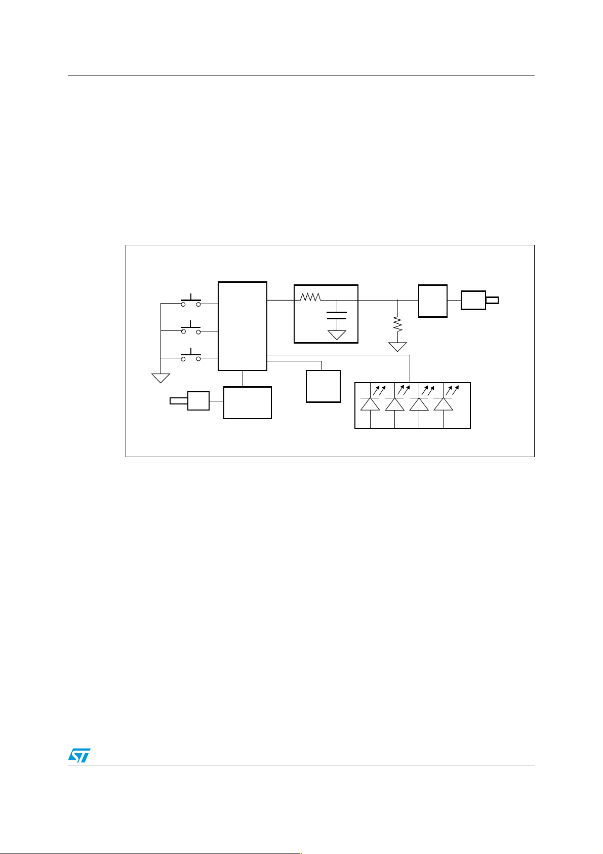
This evaluation board includes the following main components:
● 8-bit microcontroller: ST7FLITES2. However, the ST7Flite02 can also be used.
● An external 8 MBit Serial Flash, M25P80 family
● External components to build a low cost passive filter.
● An audio amplifier (TDA7233)
● 3.3V low-cost voltage regulator
Figure 1. Audio player evaluation board block diagram
ST7Lite02
DIP16
File Index
6th order
RC filter
Vol ume
Control
Powe r
Amplifier
TDA
7233
Play
Reset
Microcontroller
SPI
Serial
Flash
Volt age
External
Input
Regulator
Powe r
Supply Circuit
ZIF
Socket
Binary LED display
The main features of the evaluation board are as follows:
● Plays pre-recorded audio clips stored on an ST 8-Mbit serial Flash
● Can play up to 15 different audio files
● Easy to use Index and Play push-buttons
● Power input 6V DC
● Phone-quality sound: 8 kHz/8 bit
External
Speaker
Connection
1.1 Instructions for use
Assuming the external Flash is already programmed with sounds, you need to:
1. Power-on the board
2. Connect the board to the speaker
3. Select the desired sound by pressing the Index button. The File Index indicates the
sound to be played with the help of 4 LEDs.
4. Push the Play Sound button.
5. Adjust the volume potentiometer to your convenience.
3/23
Page 4
Audio player evaluation board overview AN2400
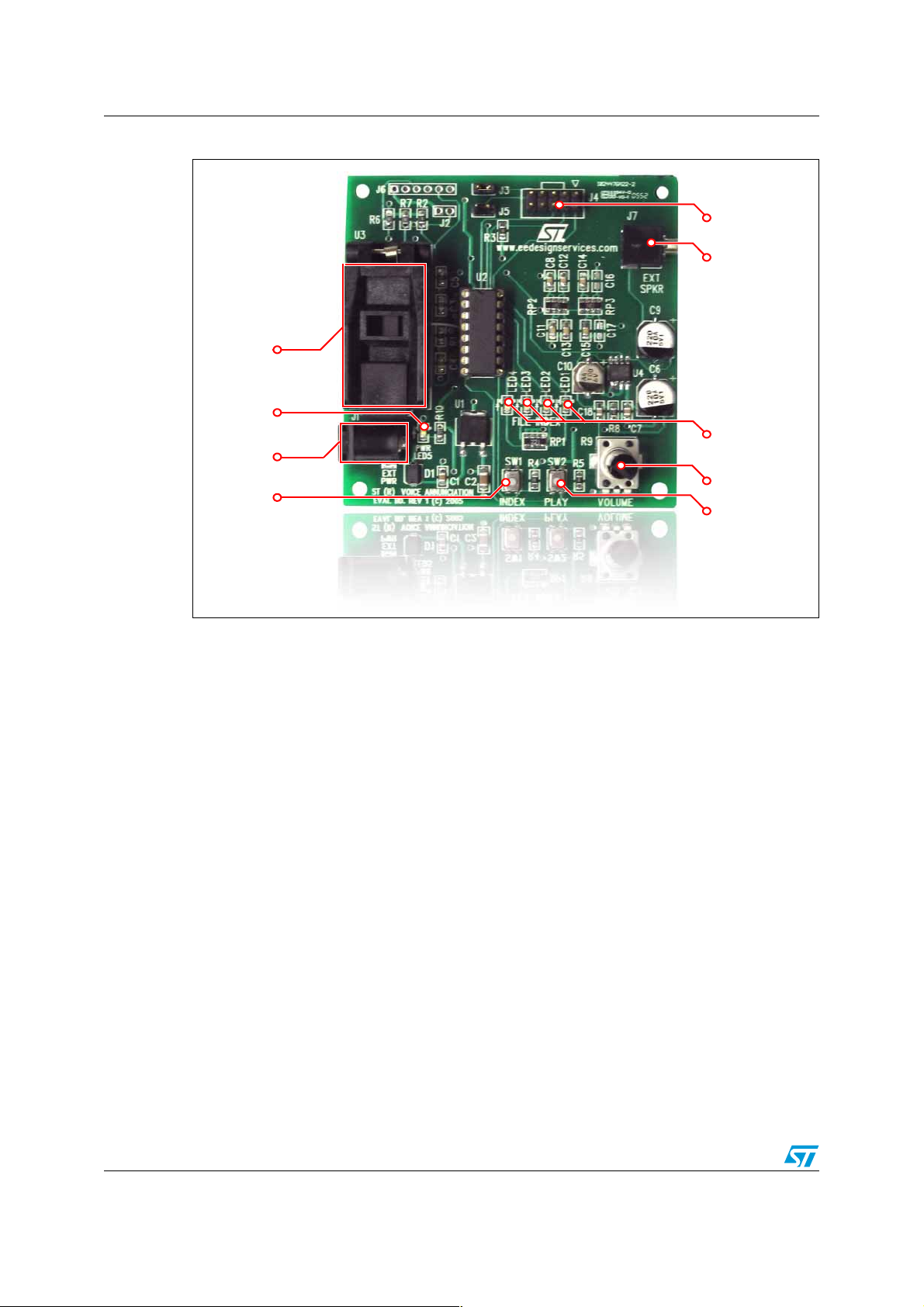
Figure 2. Labeled diagram of Audio player evaluation board
ICC Connector
External
Speaker Jack
ZIF Socket
for Flash
Power LED
File Index
Power Jack
LEDs
File Index
Switch
Volume Control
Play Switch
4/23
Page 5
AN2400 Audio player evaluation board concept
2 Audio player evaluation board concept
2.1 Audio recording
A PC is used to prepare audio to be programmed onto the external serial Flash. The file
must contain audio data as well as some basic file management structure to allow the ST7
to pick the correct audio during playback.
The serial Flash is used to store the audio files in binary format. For this purpose, it is
necessary to have the audio files in .wav format which allows them to be converted to a .bin
file to be programmed into the serial Flash.
For conversion to binary, the .wav files should have an 8 kHz sampling frequency and 8-bit
quantization format. These files are input into the provided WAV Converter utility to generate
a single .bin file.
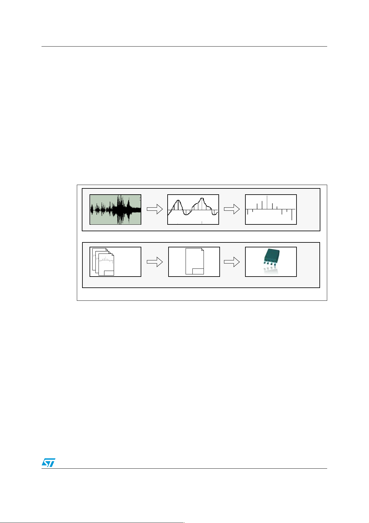
Figure 3. Sound recording flow
Original Sound Sampling Quantifying
Recording process: Can be done on a standard PC, in a recording studio, or just some existing audio samples
Standard
8kHz/8-bit
WAV
.WAV files
WAV
WAV
WAV File Storage Conversion to Binary File Burn binary file to M25P
PC Processing: Convert the .WAV files into a propriety binary file used to reprogram the onboard serial Flash
011011011
001010101
BIN
Serial Flash Memory
Once this process is completed, the board is ready to play customized sounds provided by
the user.
A sound is selected using the Index push-button, and then heard by pressing the Play
button.
5/23
Page 6
Audio reproduction flow AN2400
3 Audio reproduction flow
Figure 4. Audio reproduction flow
MCU reads data from
Serial Flash through SPI
Micro Data Processing: Complete source code free available from ST
Train of Pulses PWM
timer feature Filter
6th Order RC
Analog Filtering
Low-Pass
Filter quality/cost tradeoff can be achieved by
populating or not the filter capacitors
Reconstructed signal
to Speaker
Reproduction of “phone
quality” audio
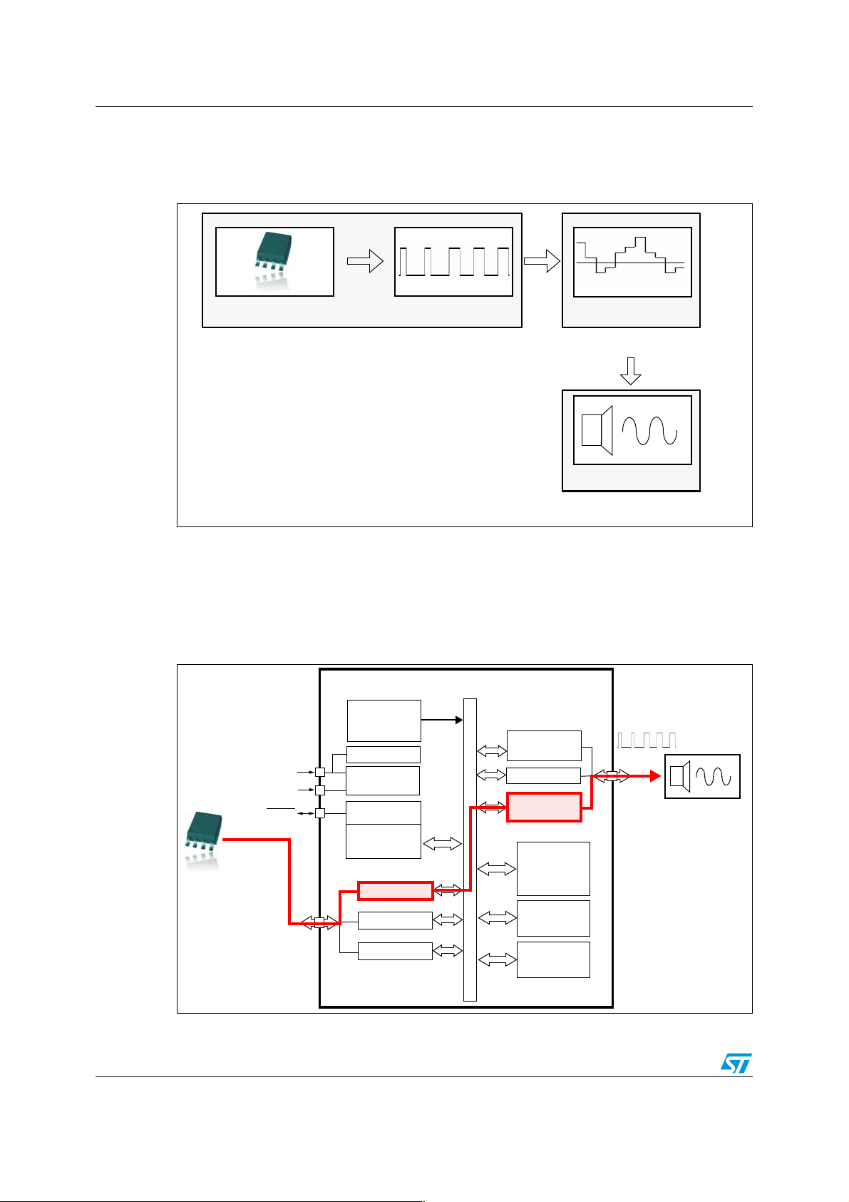
Data, which is stored in the serial Flash, is read by the microcontroller through the SPI
interface. This data is then fed through the timer registers to generate a PWM output whose
duty cycle varies according to the data value.
The sequential path of the data flow from the serial Flash to the speaker is shown in
Figure 5.
Figure 5. Flow of data from external serial flash to external speaker
Internal
SPI
CLOCK
PWM Timer Feature
LITE TIMER
w/ WATCHDOG
PORT A
12-BIT AUTO-
RELOAD TIMER
PA7:0
(8 bits)
External
Filter/Speaker
FLASH
MEMORY
ADDRESS AND DATA BUS
(1 or 1.5K Bytes)
RAM
(128 Bytes)
DATA EEPROM
(128 Bytes)
External
Serial Flash
SPI Data
Tr an s fe r
V
V
RESET
PB4:0
(5 bits)
1 MHz. RC OSC
+
PLL x 4 or x 8
LVD/AVD
DD
SS
POWER
SUPPLY
CONTROL
8-BIT CORE
ALU
PORT B
8-BIT ADC
6/23
Page 7
AN2400 Audio reproduction flow
The microcontroller initiates the communication when it selects the Flash and starts reading
the data on a full duplex, synchronous basis. Once the microcontroller reads the data, it
generates a train of pulses using the PWM feature of the 12-bit auto reload timer. This is
explained with the help of an example:
Audio samples of 8 kHz, 8-bit format are to be reproduced. This data is coded in an 8bit format (with values from 0 to 255).
To reproduce the audio with sampling rate of 8 kHz, the microcontroller outputs each
value in every 1/8000 sec (every 125 µs). This means that the period of the PWM is set
at 125µs.
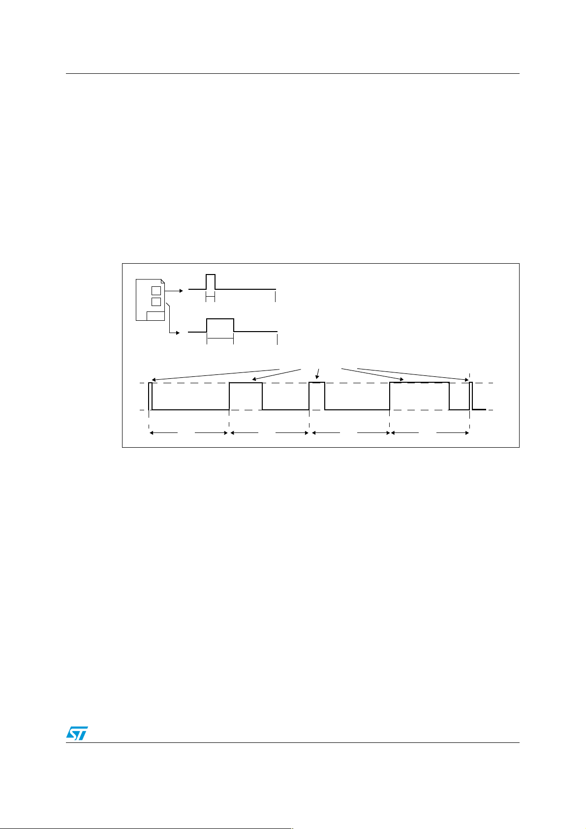
If the coded value of the audio signal is “1”, the microcontroller needs to generate the
PWM signal with a HIGH output for 1 count and LOW for the rest of the 255 counts.
This is shown in the figure below:
Figure 6. Waveform depicting the microcontroller output
1
x
BIN
Flash
1
256 256 256 256
x
255
(256 - x)
Data value of 1 is read from Flash and ART generates
a PWM pulse with a duty cycle high of length 1
with 255 low.
Data value of x is read from Flash and ART generates
a PWM pulse with a duty cycle high of length x
and (256-x) low.
Varying duty cycles
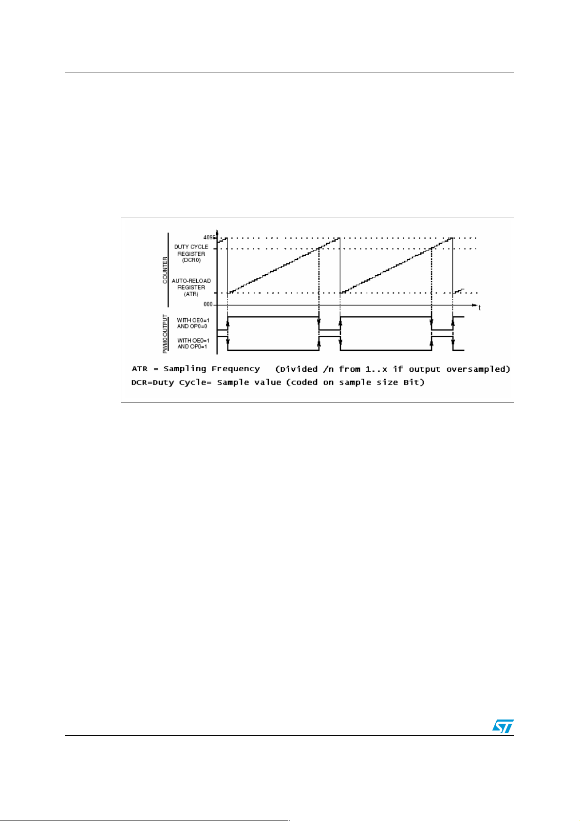
Figure 7 below shows how the duty cycle register generates this output.
This process uses a duty cycle register, a 12-bit auto reload register and an up-counter.
When an up-counter overflow occurs (OVF event), the ATR value is loaded into the upcounter, the preloaded duty cycle is transferred to the duty cycle register. The PWM0 signal
is then set to a high level. Finally, when the upcounter matches the DCRx value, the PWM0
signal is set to a low level.
To use this sequence for audio generation, the following steps are taken:
1. When the up-counter reaches 0xFFF, an overflow event occurs. At this point, the PWM
output becomes high.
2. The ATR register value is loaded into the up-counter which in this example is 0xF00.
0xF00 is selected to maintain a range of 0-FF i.e. 0xF00-0xFFF for an 8-bit resolution
.wav file.
3. The DCR lower 8-bit register (DCR0L) is loaded with a value that the microcontroller
has read from the serial Flash. The DCR0H register value remains 0x0F. In this
7/23
Page 8
Audio reproduction flow AN2400
example therefore, the microcontroller reads “1”. The complete contents of the duty
cycle register is 0xF01.
4. The PWM output remains high until the point at which the up-counter contents do not
match the DCR register contents which corresponds to the value from the serial Flash.
5. As the up-counter value matches the DCR register value, the PWM output goes low
and remains low until the next overflow, i.e. until 0xFFF.
Note: To obtain a PWM signal, the DCR register value should be greater than the up counter
starting value.
Figure 7. PWM function
The resultant output signal of the microcontroller has a duty cycle corresponding to the 8-bit
of quantization and 8kHz sampling frequency. So following that, the timer frequency will be
8 kHz * 256 = 2 MHz.
This means that 2MHz is the minimum PWM frequency needed for use of the PWM for
audio generation. With the ST7Lite device, the timer can receive Fcpu=8MHz. To utilize the
8MHz timer frequency, the firmware puts 4 times the sample value on the PWM.
The 8 kHz sampling frequency has a very high pitch and is audible to the human ear, so the
signal needs to be reconstructed, passing it through a 6th-order low pass filter. This
removes any unwanted high frequency component from the signal. The signal is then
passed to the amplifier and through to the speaker. The filter cut-off frequency is set to 8
kHz. If it is necessary to change the sampling frequency of the audio to be played, the cutoff frequency of the filter needs to be adjusted according to signal frequency range. The
human ear can detect sounds between 20Hz to 20kHz. However, a range of 4 kHz to 8kHz
is suitable for human voice, hence the 8 kHz is the minimum required sampling frequency.
The microcontroller runs on the internal RC oscillator. It is important to carefully calibrate the
internal RC frequency, as any discrepancy in f
value has a huge impact on the audio
CPU
reproduction.
8/23
Page 9

AN2400 Filter design
4 Filter design
Here, a 6th-order low pass filter is used. A low pass filter passes all the signals below the
cutoff frequency and attenuates the signal above cutoff frequency. The reason behind using
a sixth order filter is to have a steeper slope and therefore a better frequency response. It is
c r e a t e d b y c a s c a d i n g s i x f i r s t - o r d e r l o w p a s s f i l t e r s a s s h o w n i n f i g u r e b e l o w :
Figure 8. Sixth order low pass RC-filter
V
in
Calculating resistance of low pass filter:
The value of C is taken as 0.01 µf and the cutoff frequency fC is 8kHz.
RRRRRR
CC C CCC
V
out
Cutoff frequency: f
so: R = 1 / (2 π C f
= 1 / (2 π RC)
C
)
C
= 1 / (2 π (.01 µF) (8 kHz) )
= 1990 Ω
R = 1.9 kΩ
1.9 kΩ is not a standard value, so 1.8 kΩ is used.
9/23
Page 10
WAV file conversion process AN2400
5 WAV file conversion process
(Utility provided to convert .wav -> .bin)
The key point of this demonstration board is to be able to customize it to play a set of sounds
defined by the user. The user input to perform this operation will be the user .wav files. The
.wav format is part of the RIFF bitstream format. This is one of the most current of audio
formats for uncompressed PCM (Pulse Code Modulation) audio data as well as for
computer audio storage. As it is required to be able to play multiple sounds in this demo, all
audio data needs to be together in a file that can be programmed in the serial Flash. This is
the purpose of the ARF utility.
The utility generates a .bin file such that:
● It can be used to flash the content of the M25P serial Flash chip
● It is in optimized format for the ST7FLiteS2 MCU to read and playback
● It can contain up to 15 separate sounds that can be accessed individually
● 1 sec of audio uses 64 KB of Flash.
(With its 8 MB Flash, this board can playback up to 2 min of audio)
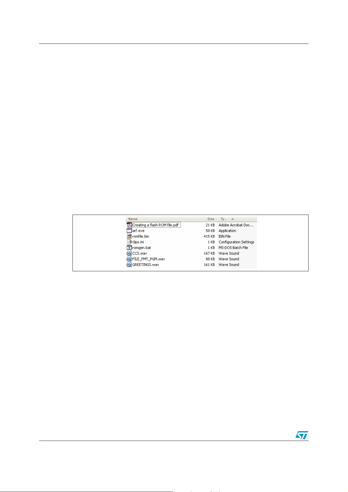
The folder where you have stored the utility should look similar to the following:
Figure 9. Files used to create a .bin file from a .wav file
1. Copy all .wav files into the same folder. (only 8 kHz/8-bit Files).
2. Copy romgen.bat and arf.exe into the same folder.
3. Edit clips.ini with names of sound clips, ensure that there are NO SPACES in the
filenames.
4. Run romgen.bat.
5. Program the Serial Flash with the romfile.bin file.
Note: 1 A semicolon in front of a line in the INI file creates a comment line which is not processed by
the ARF ROM generator utility.
2 The ARF utility program supports from 1 to 15 audio files, with a total file size supported up
to the storage capacity of the 8-Mbit ST M25P80 Serial Flash ROM chip.
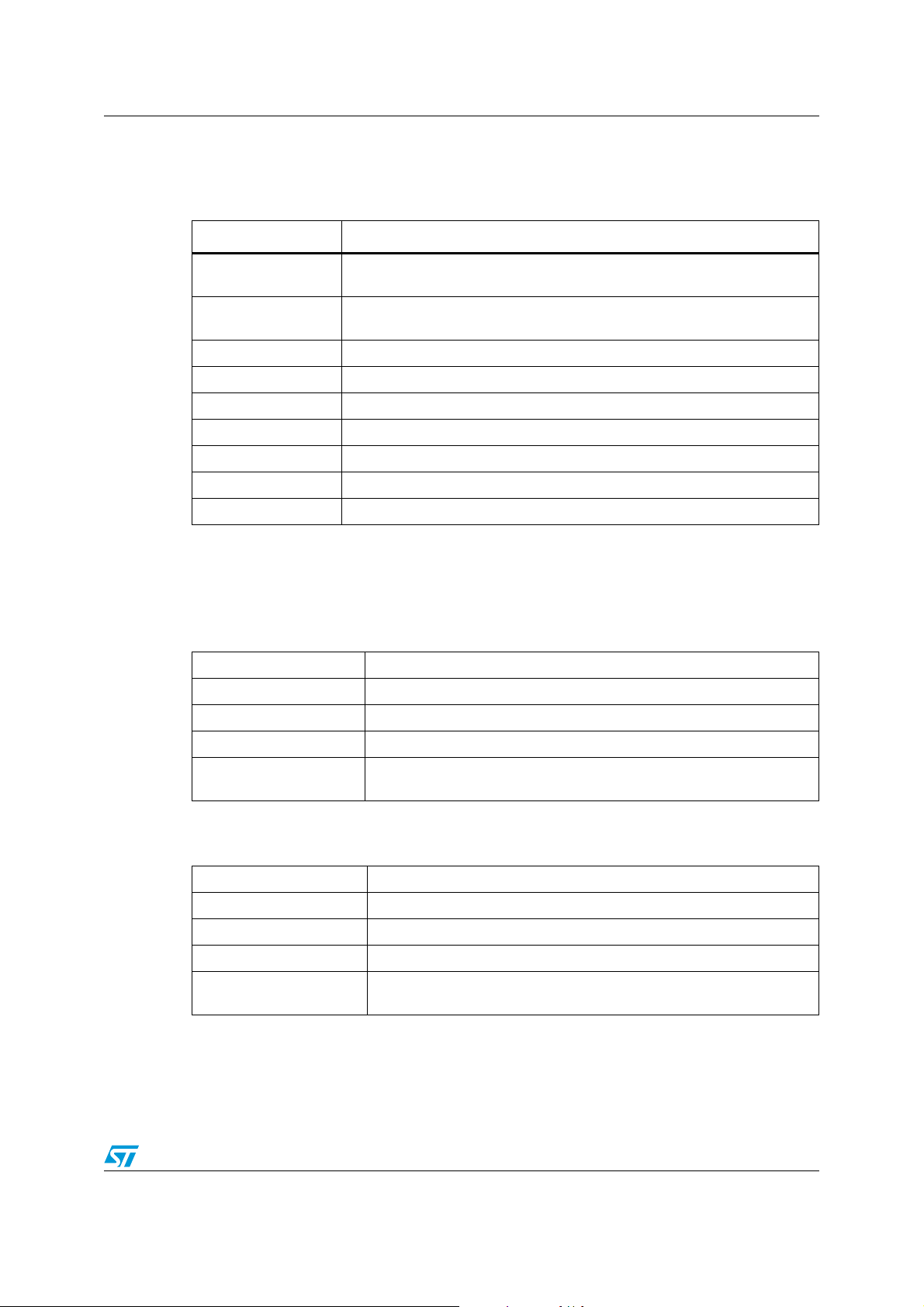
This process generates the romfile.bin file in the same folder with the following structure (as
shown in Ta bl e 1 ). The microcontroller correctly interprets this structure while accessing the
audio samples.
10/23
Page 11

AN2400 WAV file conversion process
Table 1. Storage of data in the flash
Offsets Description
00000000
00000004-00000007 Gives the first record size (LSB first)
00000008-0000000B Gives the first record start address (LSB first)
0000000C-0000000F Gives the second record size (LSB first)
00000010-00000013 Gives the second record start address (LSB first)
Gives the number of audio files stored in the serial flash. 1st
Byte contains the value 1-15. Next 3 bytes are unused.
11/23
Page 12

Conclusion AN2400
6 Conclusion
This solution provides an easy way to generate audio using an ST7 microcontroller. This can
be customized to fit wide application requirements in term of audio. The solution provided
can also be easily adapted to target a different microcontroller from the same family, or while
using a different timer a wider range of platform options (ST7, STR7…).
12/23
Page 13
AN2400 Files description
Appendix A Files description
Table 2. Files and their description
Files Description
Main.c
interrupt_vector.c
interrupt_routines.c Contains the interrupt service routines and preprocessors.
interface.h Contains the external declaration for the global variables.
interrupt_routines.h Contains the external declaration for the interrupt service routines.
define.h Contains the preprocessors and constants.
io7flite0.h Contains IO definitions for the various registers of ST7FLITES2
lib_bits.h Contains the constants (#define) and the public macros and declarations.
bitdef.h Contains the constants (#define) for the various registers of ST7FLITES2.
Contains the parameters, constants (#define), macros, global variables,
function prototypes and their definition.
Contains the basic interrupt vector tables for ST7 devices and the
preprocessors.
A.1 Function description
A.1.1 RC_calibration()
Input Parameter None
Output Parameter None
Global Variables None
Dependencies None
Description
A.1.2 IO_Init()
Input Parameter None
Output Parameter None
Global Variables None
Dependencies None
Description
Used for the RC oscillator frequency adjustment. An 8-bit RC control
register is used for the adjustment.
Used to configure the data direction register and option register in
output mode and in push pull mode respectively.
13/23
Page 14

Files description AN2400
A.1.3 SPI_Init()
Input Parameter None
Output Parameter None
Global Variables None
Dependencies None
Description
A.1.4 PWM_Init()
Input Parameter None
Output Parameter None
Global Variables None
Dependencies None
Description
A.1.5 LiteTimer_Init()
Input Parameter None
Output Parameter None
Global Variables None
Dependencies None
Description
1) Configures the SPICSR and SPICR register.
2) Enables the microcontroller in master mode.
Enables the overflow, input capture and compare interrupts.
PWM channel 0 is also enabled.
Enables the timebase interrupt as soon as the counter overflow occurs.
Thereby, time base flag is set by hardware.
A.1.6 GlobalVar_Init()
Input Parameter None
Output Parameter None
1) max_file_index
2) file_index
Global Variables
14/23
3) IButton_flag
4) PButton_flag
5) tcnt
Page 15

AN2400 Files description
Dependencies None
1) Determines the maximum file index.
2) Determines the current file index to be played.
Description
3) Gives the distinction between an index button and a play button.
4) Sets a timer counter for blinking of all the LEDs when the soundboard
is switched on.
A.1.7 LED_Display()
Input Parameter None
Output Parameter None
Global Variables None
Dependencies None
Description Switches ON the LEDs in a binary format
A.1.8 Read_1_Byte()
Input Parameter None
Output Parameter None
Global Variables fbuff [index]
Dependencies None
Description
A.1.9 Check_Indexbutton()
Input Parameter None
Output Parameter None
Global Variables IButton_flag
Dependencies
Description
A.1.10 Check_Playbutton()
Input Parameter None
Output Parameter None
Global Variables
Reads the first byte of the flash, thereby establishing a communication
path between microcontroller and flash device through SPI interfacing.
1) Key_Debounce()
2) SetNew_Index()
3) LED_Display()
Checks whether the index button has been pressed or not. If pressed
then switching over to next index file is done and thereby LED display
also changes.
15/23
Page 16

Files description AN2400
Dependencies
Description Checks which file is to be played.
A.1.11 Key_Debounce()
Input Parameter None
Output Parameter None
Global Variables tcnt
Dependencies None
Description Time delay for debouncing of switch
A.1.12 SetNew_Index()
Input Parameter None
Output Parameter None
Global Variables
Key_Debounce()
Get_Current_Pointers ()
1) IButton_flag
2) file_index
3) max_file_index
Dependencies None
Description Ensures that the index files do not exceed the required limit.
A.1.13 Get_Current_Pointers()
Input Parameter None
Output Parameter None
Global Variables None
Dependencies None
It works in the following way :
1) selects the flash
Description
2) reads the data from it
3) sends the data to microcontroller from the flash
4) reads and finds the start address of the data
A.1.14 Playbyte()
Input Parameter None
Output Parameter None
Global Variables
1) pwmrdy
2) pwm_val
16/23
Page 17

AN2400 Files description
Dependencies Key_Debounce()
Description
Plays the index files by reading the data from the flash through SPI
interface.
A.2 Interrupt routine description:
A.2.1 LTIC_ISR (Lite timer compare interrupt service routine)
Input Parameter None
Output Parameter None
Global Variables Tcnt
Dependencies none
Description
A.2.2 TO_ISR (Timer overflow interrupt service routine)
Input Parameter None
Output Parameter None
Decrements the counter from xx to 00. After decrementing, it clears
the interrupt by reading the LTCSR register.
Global Variables
Dependencies none
Description
A.2.3 TC_ISR
Input Parameter None
Output Parameter None
Global Variables None
Dependencies None
Description Clears the interrupt generated by the PWM0 signal.
1) pwmrdy
2) pwm_val
Whenever this interrupt occurs, the variable pwmrdy is incremented,
and the PWM value is loaded in the duty cycle register.
17/23
Page 18

Schematics AN2400
Appendix B Schematics
Figure 10. Schematic 1of 2
18/23
Page 19

AN2400 Schematics
Figure 11. Schematic 2 of 2
A A
5
4
3
B B
6TH
C16 THROUGH C17
NOT INSTALLED
ORDER FILTER
NOTE:
DEFAULT CONFIGURATION
LOW-PASS FILTER
LOW-COST
R9 10K POT
PANASONIC
EVU-F2AF30D14
R9 10K POT
PANASONIC
EVU-F2AF30D14
1 3
2
R8 10K
9C08052A1002FKHFT
YAEGO
R8 10K
9C08052A1002FKHFT
YAEGO
1 2
12
12
C10
100 UF6.3V CERAMIC
NICHICON
UWX0J101MCL1GB
C10
100 UF6.3V CERAMIC
NICHICON
UWX0J101MCL1GB
1 2
AVX 08055C103KAT2A
AVX 08055C103KAT2A
C18 0.1 UF50V CERAMIC
KEMET
C0805C104Z5UACTU
C18 0.1 UF50V CERAMIC
KEMET
C0805C104Z5UACTU
0.022 UF 50V CERAMIC
AVX
08055G223ZAT2AC50.022 UF 50V CERAMIC
AVX
08055G223ZAT2A
C C
C17
0.01 UF 50V 10% CERAMIC
AVX 08055C103KAT2A
C17
0.01 UF 50V 10% CERAMIC
AVX 08055C103KAT2A
4 5
678
C16
0.01 UF 50V 10% CERAMIC
C16
0.01 UF 50V 10% CERAMIC
12
12
C5
AVX 08055C103KAT2A
AVX 08055C103KAT2A
1 2
123
12
C15
0.01 UF 50V 10% CERAMIC
C15
0.01 UF 50V 10% CERAMIC
1 2
RP3
RES ARRAY1.8K
CTS743C083182JTR
RP3
RES ARRAY1.8K
CTS743C083182JTR
C14
0.01 UF 50V 10% CERAMIC
AVX 08055C103KAT2A
C14
0.01 UF 50V 10% CERAMIC
AVX 08055C103KAT2A
POURED GROUND
PLANE
C13
0.01 UF 50V 10% CERAMIC
AVX 08055C103KAT2A
C13
0.01 UF 50V 10% CERAMIC
AVX 08055C103KAT2A
4 5
C12
0.01 UF 50V 10% CERAMIC
AVX 08055C103KAT2A
C12
0.01 UF 50V 10% CERAMIC
AVX 08055C103KAT2A
12
678
ROUTED WITHIN A
GROUND GUARD OR
1 2
123
12
D D
APWM SHOULD BE
C11
0.01 UF 50V 10% CERAMIC
AVX 08055C103KAT2A
C11
0.01 UF 50V 10% CERAMIC
AVX 08055C103KAT2A
RP2
RES ARRAY1.8K
CTS743C083182JTR
RP2
RES ARRAY1.8K
CTS743C083182JTR
C8
0.01 UF 50V 10% CERAMIC
AVX 08055C103KAT2A
C8
0.01 UF 50V 10% CERAMIC
AVX 08055C103KAT2A
APWM
5
4
3
2
+IN8-IN7MUTE
1
3
U4
AUDIOAMP
ST TDA7233DU4AUDIOAMP
12
R11 4.7
RC0805JR-074R7L
YAEGO
R11 4.7
RC0805JR-074R7L
YAEGO
SPEAKER
ST TDA7233D
ECE-V1AA221PC9220 UF10V
ECE-V1AA221P
KEMET
C0805C104Z5UACTU
KEMET
C0805C104Z5UACTU
EXTERNAL
2
Title
Size DocumentNumber Rev
Date: Sheet
Title
Size DocumentNumber Rev
Date: Sheet
Title
Size DocumentNumber Rev
Date: Sheet
Voice Annunciation Evalution Board
1
of35Wednesday,June 28, 2006
of35Wednesday,June 28, 2006
of35Wednesday,June 28, 2006
6
GND
SVR
4
GND2
V+
ECE-V1AA221PC6220 UF10V
OUT
5
1 2
C9
220 UF10V
PANASONIC
PANASONIC
12
C19
0.1 UF 50V CERAMIC
C19
0.1 UF 50V CERAMIC
123
ECE-V1AA221P
J7 SPEAKERJACK
CUIINC MJ-2506N
CP-2506N-ND
J7 SPEAKERJACK
CUIINC MJ-2506N
CP-2506N-ND
C6
220 UF10V
PANASONIC
PANASONIC
12
12
C7 0.1 UF 50V CERAMIC
C7 0.1 UF 50V CERAMIC
KEMET
C0805C104Z5UACTU
KEMET
C0805C104Z5UACTU
3P3V
2
1
19/23
Page 20

Bill of materials AN2400
Appendix C Bill of materials
Table 3. Bill of materials for Audio player evaluation board
Manufacturer
Index Quantity Reference
Value /
Generic Part
Number
Package Manufacturer
ordering
code/
Orderable
Part Number
16
21C2
31C5
4 2 C9,C6 220 UF 10V 8 * 6.2 mm PANASONIC
58
61C10
7 1 D1 DIODESTP SMA ST STPS140A
81J1
91J2
10 2 J5, J3 2 PIN HDR 2 PIN HDR MOLEX 22-28-4024
11 1 J4 HEADER 2X5 HEADER 2X5 MOLEX 10-89-1101
12 1 J6 HEADER 1X6 HEADER 1X6 MOLEX 22-28-4064
C1, C3, C4, C7,
C18, C19
C8, C11, C12, C13,
C14, C15, C16,
C17
0.1 UF 50V
CERAMIC
10 UF CER
25V
0.022 UF 50V
CERAMIC
0.01 UF 50V
10%
CERAMIC
100 UF 6.3V
CERAMIC
POWER JACK
2.5MM
NOT
INSTALLED
SMD0805 KEMET
1206 PANASONIC
SMD0805 AVX
SMD0805 AVX
6.3 *5.4 mm NICHICON
POWER
JACK-
14.17 * 8.96
mm
NOT
INSTALLED
CUI PJ-102B
MOLEX 22-28-4024
C0805C104Z5
UACTU
ECJ3YB1E106M
08055G223ZA
T2A
ECEV1AA221P
08055C103KA
T2A
UWX0J101MC
L1GB
13 1 J7
14 5
15 1 RP1
16 2 RP2, RP3
17 6
18 2 R6, R7 100K SMD PANASONIC
20/23
LED1, LED2,
LED3, LED4, LED5
R1, R2, R3, R4, R5,
R8
SPEAKER
JACK
GREEN LED SMD0805 LITEON
RES ARRAY
220
RES ARRAY
1.8K
10K SMD0805 YAEGO
SPEAKER
JACK
0805 CTS 743C083221J
0805 CTS
CUI INC MJ-2506N
LT STC170GKT
743C083182J
TR
9C08052A100
2FKHFT
ERJ6GEYJ104V
Page 21

AN2400 Bill of materials
Manufacturer
Index Quantity Reference
Value /
Generic Part
Number
Package Manufacturer
ordering
code/
Orderable
Part Number
19 1 R9 10K POT
20 1 R10 220E SMD0805 YAEGO
21 1 R11 4.7E SMD0805 YAEGO
PUSH
22 2 SW1, SW2
23 1 U1 3.3 VREG DPAK ST KF33BDT
24 1 U2 MCU DIP16 ST
25 1 U3
26 1 U4 AUDIO AMP SO8 ST TDA7233D
27 1 U5
BUTTON
SPST
WIDE ZIF
SOCKET
8-MBIT
FLASH
11.48 * 9.71
mm
4.7X3.5X2.1
mm
SO8
SO8W ST
PANASONIC
PANASONIC EVQ-P2K02Q
EMULATION
TECHNOLOGY
EVUF2AF30D14
RC0805JR07220RL
RC0805JR074R7L
ST7FLITES2Y
0B6
S-SOP-00008-B
M25P80VMW6G
21/23
Page 22

Revision history AN2400
7 Revision history
Table 4. Document revision history
Date Revision Changes
10-Nov-2006 1 Initial release.
22/23
Page 23

AN2400
Please Read Carefully:
Information in this document is provided solely in connection with ST products. STMicroelectronics NV and its subsidiaries (“ST”) reserve the
right to make changes, corrections, modifications or improvements, to this document, and the products and services described herein at any
time, without notice.
All ST products are sold pursuant to ST’s terms and conditions of sale.
Purchasers are solely responsible for the choice, selection and use of the ST products and services described herein, and ST assumes no
liability whatsoever relating to the choice, selection or use of the ST products and services described herein.
No license, express or implied, by estoppel or otherwise, to any intellectual property rights is granted under this document. If any part of this
document refers to any third party products or services it shall not be deemed a license grant by ST for the use of such third party products
or services, or any intellectual property contained therein or considered as a warranty covering the use in any manner whatsoever of such
third party products or services or any intellectual property contained therein.
UNLESS OTHERWISE SET FORTH IN ST’S TERMS AND CONDITIONS OF SALE ST DISCLAIMS ANY EXPRESS OR IMPLIED
WARRANTY WITH RESPECT TO THE USE AND/OR SALE OF ST PRODUCTS INCLUDING WITHOUT LIMITATION IMPLIED
WARRANTIES OF MERCHANTABILITY, FITNESS FOR A PARTICULAR PURPOSE (AND THEIR EQUIVALENTS UNDER THE LAWS
OF ANY JURISDICTION), OR INFRINGEMENT OF ANY PATENT, COPYRIGHT OR OTHER INTELLECTUAL PROPERTY RIGHT.
UNLESS EXPRESSLY APPROVED IN WRITING BY AN AUTHORIZE REPRESENTATIVE OF ST, ST PRODUCTS ARE NOT DESIGNED,
AUTHORIZED OR WARRANTED FOR USE IN MILITARY, AIR CRAFT, SPACE, LIFE SAVING, OR LIFE SUSTAINING APPLICATIONS,
NOR IN PRODUCTS OR SYSTEMS, WHERE FAILURE OR MALFUNCTION MAY RESULT IN PERSONAL INJURY, DEATH, OR
SEVERE PROPERTY OR ENVIRONMENTAL DAMAGE.
Resale of ST products with provisions different from the statements and/or technical features set forth in this document shall immediately void
any warranty granted by ST for the ST product or service described herein and shall not create or extend in any manner whatsoever, any
liability of ST.
ST and the ST logo are trademarks or registered trademarks of ST in various countries.
Information in this document supersedes and replaces all information previously supplied.
The ST logo is a registered trademark of STMicroelectronics. All other names are the property of their respective owners.
© 2006 STMicroelectronics - All rights reserved
STMicroelectronics group of companies
Australia - Belgium - Brazil - Canada - China - Czech Republic - Finland - France - Germany - Hong Kong - India - Israel - Italy - Japan -
Malaysia - Malta - Morocco - Singapore - Spain - Sweden - Switzerland - United Kingdom - United States of America
www.st.com
23/23
 Loading...