

Page 1

AN2372
Application note
Low cost sinusoidal control of BLDC motors with
Hall sensors using ST7FMC
Introduction
BLDC motors are the workhorses in most light industrial applications. In some cases, Halleffect position sensors are used to simplify control logics for controlling these motors. BLDC
motors, by the nature of currents through them, are somewhat noisy and a little less
efficient. These disadvantages plus the cost of sensors are an integral part of these drive
systems. However, if the motor can be driven with sinusoidal currents, preferably with only
one Hall-effect sensor, these drawbacks can be greatly reduced.
A 3-phase Permanent Magnet Synchronous Motor (PMSM) has permanent magnets on the
rotor and current-carrying windings on the stator. There are two modes of control:
■ as a BLDC motor, where, based on rotor position, only two windings carry current at any
given time (reducing winding utility by 33%)
■ as a three phase AC motor, where three-phase sinusoidal voltages are applied on all
three windings and all three windings carry current at all times
The comparison chart below shows the advantages of controlling the PMSM motor like an
AC motor instead of a BLDC motor.
AC motor BLDC motor
Currents are sinusoidal Currents are rectangular
Rectangular currents have harmonics in odd
Current harmonics in switching frequency range
Lower audible noise Higher audible noise
Lower core losses in motor Higher core losses
Current peak value lesser, power circuit
dimensioning can be optimized
Phase rms current lower Phase rms current higher
Electric torque developed is flat Torque has commutation ripples
Higher switching losses in inverter as all switches
take PWM
Implementation is little complex Implementation is simple
Implementation of this scheme with an ST7FMC can give additional advantages such as
load angle control to help optimize the motor current, and voltage foldback current protection
to help limit motor currents by reducing the applied voltage to implement current limit
control.
multiples of fundamental frequency (which are in
audible range) plus switching frequency
harmonics.
Current peak value higher. Higher dimensioning
of power circuit
Switching losses minimal because only one of the
switches take PWM
July 2006 Rev 1 1/13
www.st.com
Page 2

Contents AN2372
Contents
1 Theory of operation and control . . . . . . . . . . . . . . . . . . . . . . . . . . . . . . . 3
2 Experimental implementation using ST7FMC . . . . . . . . . . . . . . . . . . . . 5
2.1 Speed and absolute position estimation . . . . . . . . . . . . . . . . . . . . . . . . . . . 7
2.2 Current control . . . . . . . . . . . . . . . . . . . . . . . . . . . . . . . . . . . . . . . . . . . . . . 8
3 Conclusion . . . . . . . . . . . . . . . . . . . . . . . . . . . . . . . . . . . . . . . . . . . . . . . . . 9
Appendix A Phase current comparison between 6 step BLDC drive and sine
BLDC drive for same power output10
Appendix B Test procedure . . . . . . . . . . . . . . . . . . . . . . . . . . . . . . . . . . . . . . . . . . 11
4 Revision history . . . . . . . . . . . . . . . . . . . . . . . . . . . . . . . . . . . . . . . . . . . 12
2/13
Page 3
AN2372 Theory of operation and control
1 Theory of operation and control
In three-phase AC motors, currents flowing in the stator windings create a magnetic field
with a definite magnitude and orientation inside the motor. When a DC current passes
though these windings, it produces a static magnetic field. The permanent magnets in a free
spinning rotor interact with the stator flux and experience a force of attraction to fall in line
with the stator flux and lock with it. If now the stator flux orientation is changed by adjusting
the stator currents, the rotor that is already locked with the stator flux, also changes its
orientation to take the new position of the stator flux. If the stator is now excited with
sinusoidal varying currents, the stator flux inside the motor spins at the frequency of its
sinusoidal currents and pulls along the rotor at this frequency.
The ability of the rotor to stay locked with the stator flux depends on the strength of the
magnetic fields and the magnitude of load torque disturbances on the rotor. Once the rotor
is in motion, if at any time the it falls out of alignment with the stator flux, it cannot spin
anymore and comes to a halt. If the stator is still excited with sinusoidal currents, then the
rotor experiences pulsating torque in either direction at the frequency of stator currents.
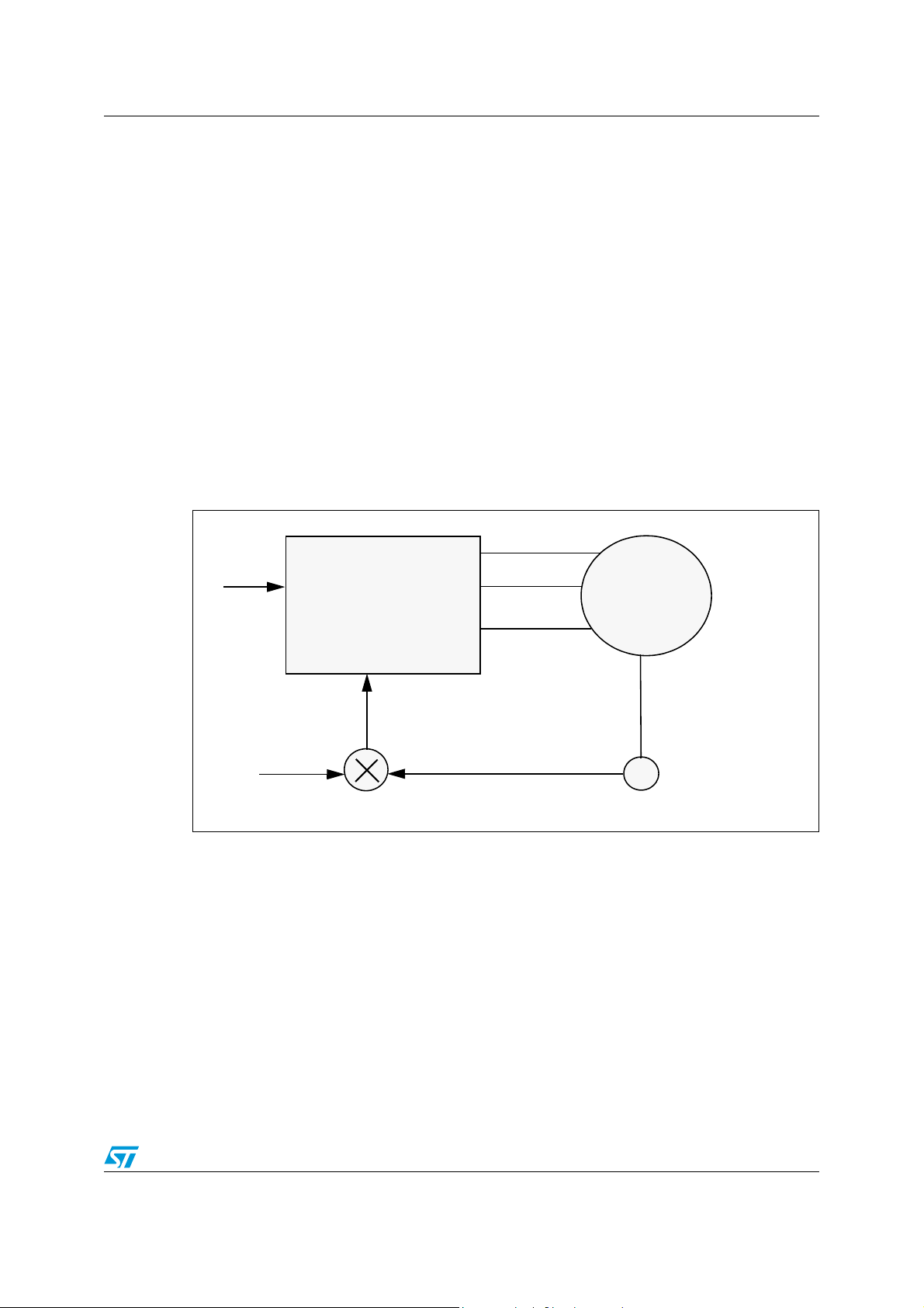
Figure 1. Self control of PMSM
V
m
3 Phase
PWM
PMSM
Generator
and Inverter
ρ
δθ
++
Absolute Position Sensor
However, this situation can be overcome if we force the sinusoidal angular values of stator
currents to correspond to the angular position of the rotor (plus an offset) as shown in
Figure 1. What this means is that even if the rotor tries to fall out of alignment for any reason,
since the stator current (which determines the stator flux magnitude and orientation)
depends only on the angular position of the rotor, it pushes/pulls the stator flux in the
direction of the rotor disturbance to maintain alignment, thereby giving improved stability
and control.
Under this condition, the PMSM motor acts like a DC motor where commutation is
performed by inverter switches and the speed is determined by the magnitude of applied
voltage. The frequency of applied sinusoidal voltage varies directly with speed and
automatically tracks itself to a value such that it matches with the V/f ratio for the motor. For
precise speed maneuvers, load angle tuning can be brought into play. For operations in field
weakening mode, applied voltage magnitude can remain at the maximum level and the load
angle should be increased appropriately.
3/13
Page 4
Theory of operation and control AN2372
Even though it acts like a DC motor, it still follows the basic theory of AC synchronous motor
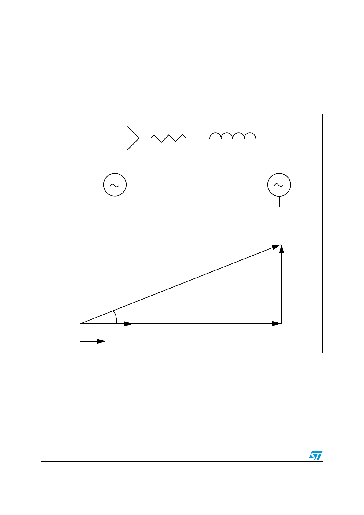
control. A single-phase equivalent circuit of the motor and a phasor diagram of motor
voltages and current are shown in Figure 2. By adjusting the phase angle between back-emf
and applied voltage, and/or the magnitude of applied voltage, the power factor of the
machine can be set to unity. This helps to maximize the power output for a given value of
phase current and to minimize the inverter rating.
Figure 2. PMSM phasor diagram at UPF
I
s
R
s
L
s
V
s
V
= [Es + IsRs] + j[ωLs]
s
E
s
V
jωLsI
s
δ
RsI
s
I
s
To implement this control, knowledge of rotor position is necessary. An absolute position
encoder may give incredibly accurate resolution and precision, but its cost is very
prohibitive. On the other hand, Hall sensors mounted in BLDC motors give a very course
resolution of close to 60° to 180° depending on the number of sensors, but they are
inexpensive. They generate rising/falling edges at these positions to indicate the angular
value at that point. However, to get intermediate angular positions of the rotor between
these edges, additional intelligence is needed by the controller for estimation.
E
b
4/13
Page 5

AN2372 Experimental implementation using ST7FMC
2 Experimental implementation using ST7FMC
The power of ST7MC to control BLDC motors with trapezoidal flux distribution, in 6 step
mode, is well known. In addition to this, ST7MC is also capable of delivering three phase
sinusoidal complementary PWMs with programmable dead time insertion to control a twolevel three-phase inverter that can drive any three-phase loads. It has a speed feedback
block that can either count the number of encoder pulses in a given time frame (in encoder
mode) or identify the time lapsed between two consecutive tacho edges (in tacho mode). In
the experiment performed using ST7MC on a three-phase PMSM, three-phase PWM
generation and speed feedback in tacho mode are used.
The control block diagram is shown in Figure 3. A speed command from the user is passed
through a ramper that sets the acceleration and deceleration rates and generates a speed
command for closed loop control. This is compared with a speed feedback estimate and the
error is passed through a PI controller that generates the magnitude reference for a 3 phase
sine voltage to be applied on the motor. Usually speed loops set the current reference for an
inner current loop for current controlled ramp up and ramp down. But this is handled in a
simplified manner and is described in Section 2.2. Speed feedback is estimated as
described in Section 2.1.
Figure 3. Implementation block diagram
3 Phase
PWM
Generator
and Inverter
ρ
δ
+
+
θ
PMSM
Position
Hall
ω
set
Ramper
PI
Controller
ω*
+
-
V
m
Current
limiter
ω
Vm’
F(ω)
θ represents the estimated angular position of phase back emf A at any given instant. δ
represents the angle enforced between the back emf and applied stator voltages. By
controlling this value, the motor can be made to operate in unity power factor. In this
experiment, the load is assumed to be a friction load. This means that the load torque
increases linearly with speed. To obtain close to unity power factor at all speeds, the load
angle is varied linearly with speed. Provision is given on this test setup to exclude load angle
compensation to study the difference in performance. The effect of load angle compensation
is predominantly visible at higher loads and speeds. With load angle compensation, the
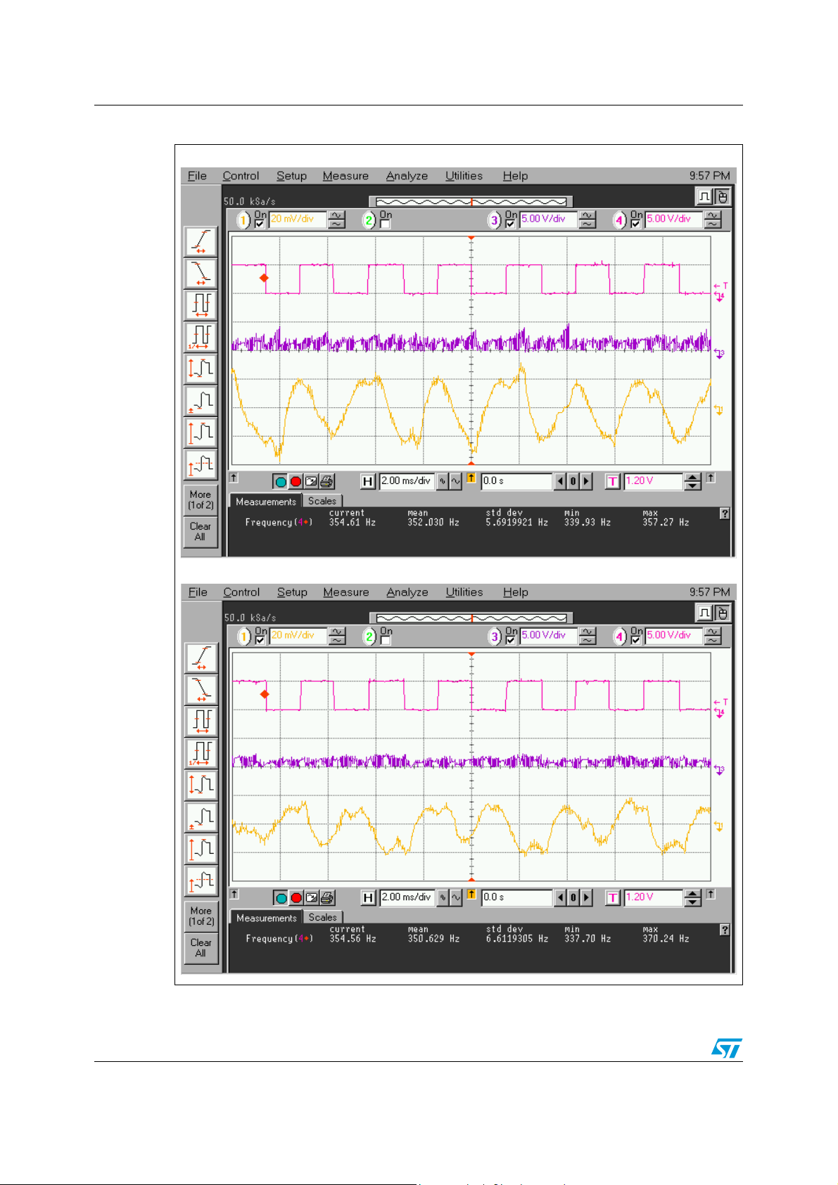
phase currents and DC link currents are appreciably lower than without it under same load
conditions and the waveforms are shown in Figure 4.
5/13
Speed and
Absolute position
estimator
Page 6
Experimental implementation using ST7FMC AN2372
Figure 4. Experimental waveforms with and without load angle compensation
Without load angle compensation
With load angle compensation
6/13
Page 7

AN2372 Experimental implementation using ST7FMC
2.1 Speed and absolute position estimation
The control scheme requires instantaneous position of back emf A to generate sinusoidal
PWM pulses for motor control. However, with only a Hall sensor feedback, that generates
only two edges within a 360° electrical cycle (corresponding to say 0° and 180°),
instantaneous position information is not available. To obtain the intermediate values, an
estimation of rotor speed is required, so that an integration of rotor speed at the pwm update
period gives the rotor position at these instants.
The basic estimation scheme is as follows:
θ is the estimated angle
θ
is the actual rotor angle at instant of a given Hall edge
H
ω is the rotor speed
At the instant of a Hall edge, θ=θ
H
For intermediate positions, for use in pwm update routines,
θ ⇐ ω.T
pwmupdate
+ θ
Figure 5. Hall edge detection and period measurement using ST7FMC
MTIM : MTIML
IS0 IS1
Hall A
Hall B
Hall C
MZREG : MZPRV
+
MUX
-
However, there are two different methods to estimate the rotor speed:
1. division method
2. PLL method
There are some commonalities between these methods. Figure 5 shows a simplified
diagram of Hall feedback connection to ST7FMC. IS1 and IS0 bits are used to connect one
of the Hall inputs to the comparator that will next change its output state after the current
one. When the comparator detects a state change, the contents of a free running timer
(MTIMH:MTIML) are captured into (MZREG:MZPRV) and the timer is reset to zero, and an
interrupt (C) is generated. Inside the C ISR, the Hall sensor states are read, θ
and θ=θ
is implemented.
H
is identified
H
In the division method, rotor speed is calculated on the basis of time difference between two
consecutive edges. With 1 or 3 Hall sensors feedback, consecutive edges correspond to
180° or 60° respectively. The existing motor has 3 sensors and hence captured period
corresponds to 60 electrical degrees.
7/13
Page 8

Experimental implementation using ST7FMC AN2372
Electrical speed ω = 2π /(T
Or,
ω = 2π /(6. T
If only one Hall sensor is present, the captured period corresponds to 180°, and hence
ω = π / T
In the PLL method,
ω = k.Σ(θ
180
H
60
- θ)
)
2.2 Current control
A conventional speed control loop sets current reference for an inner current loop. Though it
is very relevant for the overall control structure, it poses a few challenges. Since the phase
currents are sinusoidal, extracting a DC equivalent torque current requires at least two
phase currents and Park Clark transformations in the control loop. This needs two current
sensors and a high MIPS computing engine. Attempting to extract all three phase currentrelated information from the DC link current requires additional timer hardware/logics and
CPU MIPS. These requirements are obviously complicated and expensive.
Figure 6. Voltage foldback current limit control implementation using ST7FMC
360
)
Vm*
Vm’
+
-
I
limit
+
-
I
dclink
Hence a cost effective voltage foldback current limit control is implemented that fits very well
with the ST7FMC architecture. The control block diagram is shown in Figure 6. ST7FMC
has an on-chip opamp and a comparator. This opamp promotes the use of a low value shunt
resistor whose weak output can be amplified, thereby minimizing its power dissipation. The
current signal from the opamp can be connected to the comparator whose output is tied to
an interrupt generator. If the applied motor voltage is high leading to heavy currents in the
DC link, such that the comparator detects over current condition, it generates an interrupt
where, in its interrupt subroutine, the applied voltage is decremented marginally by dV. If this
condition is continuously identified during succeeding PWM cycles, the applied voltage is
constantly decremented in each interrupt, until the peak current flowing through the DC link
is below the reference value. At this point, the motor operates at a voltage and speed
corresponding to current limit. Since the voltage magnitude is reduced instead of clipping
the on times of inverter switches, the motor currents continue to be sinusoidal. From a
control standpoint, current loop implementation is highly simplified and the PMSM motor is
controlled like a DC motor.
Digital
translator
0
dV
8/13
Page 9

AN2372 Conclusion
3 Conclusion
A control implementation on a PMSM motor as described in this document was
implemented using ST7FMC and the performance was found to be satisfactory. Noise was
drastically lower. At high speeds, power consumption of a sinusoidal drive was marginally
lower than with traditional style control as with a BLDC motor. A fair comparison between
the efficiencies of these schemes is not trivial as it involves various factors such as inverter
switching frequency, inverter voltage drop, transient behavior of power switches in the
inverter, motor currents and its winding resistance.
9/13
Page 10

Phase current comparison between 6 step BLDC drive and sine BLDC drive for same power out-
Appendix A Phase current comparison between 6 step
BLDC drive and sine BLDC drive for same
power output
For same power output, average DC link current is same
6 Step BLDC motor phase currents:
I
= 2. Id /3
av
I
rms(BLDC)
Sine-drive motor phase currents:
I
= 2. Im / π
av
Where,
I
= (π/3). Id → under same power delivery
m
I
rms(SINE)
I
rms(SINE)
This shows that with a sine-drive BLDC approach, the phase rms current is lower by nearly
10% compared to a 6 step drive.
= sqrt(2/3).I
= 0.8165 . I
d
= [π / (3.sqrt(2))] . I
= 0.74 . I
d
/ I
rms(BLDC)
d
d
= 0.906
10/13
Page 11

AN2372 Test procedure
Appendix B Test procedure
The software attached with this application note can be downloaded and tested on the
ST7FMC starter kit. The test procedure is as follows:
1. Configure the jumpers for sensored BLDC mode.
2. Set W12 to FIXED
3. POT1 sets the current reference. Set it to a middle position
4. RV1 sets magnitude reference for sine output. Set to zero (CCW)
5. RV2 sets load angle. Set to mid position (0°). Turning CW increases the load angle and
CCW takes it negative (max / min is +/-90°)
6. Yellow button SW1 is the ON/OFF switch. Press it to turn ON.
7. Turn RV1 CW and motor starts running
8. Change POT1, RV1 and RV2 for experimenting with current limit, sine magnitude and
load angle
9. Pressing SW1 again turns off the motor.
11/13
Page 12

Revision history AN2372
4 Revision history
Table 1. Document revision history
Date Revision Changes
11-Jul-2006 1 Initial release.
12/13
Page 13

AN2372
Please Read Carefully:
Information in this document is provided solely in connection with ST products. STMicroelectronics NV and its subsidiaries (“ST”) reserve the
right to make changes, corrections, modifications or improvements, to this document, and the products and services described herein at any
time, without notice.
All ST products are sold pursuant to ST’s terms and conditions of sale.
Purchasers are solely responsible for the choice, selection and use of the ST products and services described herein, and ST assumes no
liability whatsoever relating to the choice, selection or use of the ST products and services described herein.
No license, express or implied, by estoppel or otherwise, to any intellectual property rights is granted under this document. If any part of this
document refers to any third party products or services it shall not be deemed a license grant by ST for the use of such third party products
or services, or any intellectual property contained therein or considered as a warranty covering the use in any manner whatsoever of such
third party products or services or any intellectual property contained therein.
UNLESS OTHERWISE SET FORTH IN ST’S TERMS AND CONDITIONS OF SALE ST DISCLAIMS ANY EXPRESS OR IMPLIED
WARRANTY WITH RESPECT TO THE USE AND/OR SALE OF ST PRODUCTS INCLUDING WITHOUT LIMITATION IMPLIED
WARRANTIES OF MERCHANTABILITY, FITNESS FOR A PARTICULAR PURPOSE (AND THEIR EQUIVALENTS UNDER THE LAWS
OF ANY JURISDICTION), OR INFRINGEMENT OF ANY PATENT, COPYRIGHT OR OTHER INTELLECTUAL PROPERTY RIGHT.
UNLESS EXPRESSLY APPROVED IN WRITING BY AN AUTHORIZED ST REPRESENTATIVE, ST PRODUCTS ARE NOT
RECOMMENDED, AUTHORIZED OR WARRANTED FOR USE IN MILITARY, AIR CRAFT, SPACE, LIFE SAVING, OR LIFE SUSTAINING
APPLICATIONS, NOR IN PRODUCTS OR SYSTEMS WHERE FAILURE OR MALFUNCTION MAY RESULT IN PERSONAL INJURY,
DEATH, OR SEVERE PROPERTY OR ENVIRONMENTAL DAMAGE. ST PRODUCTS WHICH ARE NOT SPECIFIED AS "AUTOMOTIVE
GRADE" MAY ONLY BE USED IN AUTOMOTIVE APPLICATIONS AT USER’S OWN RISK.
Resale of ST products with provisions different from the statements and/or technical features set forth in this document shall immediately void
any warranty granted by ST for the ST product or service described herein and shall not create or extend in any manner whatsoever, any
liability of ST.
ST and the ST logo are trademarks or registered trademarks of ST in various countries.
Information in this document supersedes and replaces all information previously supplied.
The ST logo is a registered trademark of STMicroelectronics. All other names are the property of their respective owners.
© 2006 STMicroelectronics - All rights reserved
STMicroelectronics group of companies
Australia - Belgium - Brazil - Canada - China - Czech Republic - Finland - France - Germany - Hong Kong - India - Israel - Italy - Japan -
Malaysia - Malta - Morocco - Singapore - Spain - Sweden - Switzerland - United Kingdom - United States of America
www.st.com
13/13
 Loading...