

Page 1

AN2341
Application note
Programming ST10F27x/F25x CAN interrupt drivers
Introduction
This application note describes the CAN interrupt drivers of the ST10F27x/ST10F25x and
provides programming examples that can be used to define interrupt schemes and write
interrupt drivers. Two C-CAN modules are implemented on ST10F27x/ST10F25x, mapped
on XBUS.
Interrupt sources, the way the sources of interrupts are identified and the two methods of
handling interrupts are described: One using the hardware features of the CAN modules
and the other through polling internal sources.
Programming the CAN interrupt drivers through CAN hardware features uses the RXIE and
TXIE bits of each message object. All 32 message objects are accessed through interface
registers. T w o sets of register are available for each module, for example CANxIF1 registers
can be used to read from a message object whereas CANxIF2 registers can be used to
write into a message object. Whenever a message is transmitted or received by a message
object, the corresponding interrupt is serviced according to its priority (based on the value of
IntId). This method requires minimum CPU overhead and is the preferred method for most
applications.
CAN polling generates an interrupt whenever a successful transmission or reception occurs.
Polling is high in CPU overhead, as the CPU is interrupted every time a message is
acknowledged on the CAN bus. Therefore, programming the interrupt driver using polling is
only recommended for small networks.
Sample programs are provided for each method as examples.
May 2006 Rev 1 1/26
www.st.com
Page 2

Contents AN2341
Contents
1 Interrupt sources and identification . . . . . . . . . . . . . . . . . . . . . . . . . . . . 3
1.1 Global interrupt sources . . . . . . . . . . . . . . . . . . . . . . . . . . . . . . . . . . . . . . . 3
1.2 Individual interrupt sources . . . . . . . . . . . . . . . . . . . . . . . . . . . . . . . . . . . . 4
1.2.1 Status interrupts . . . . . . . . . . . . . . . . . . . . . . . . . . . . . . . . . . . . . . . . . . . . 4
1.2.2 Error interrupts . . . . . . . . . . . . . . . . . . . . . . . . . . . . . . . . . . . . . . . . . . . . . 4
1.2.3 Message-specific interrupts . . . . . . . . . . . . . . . . . . . . . . . . . . . . . . . . . . . 5
2 Handling interrupts . . . . . . . . . . . . . . . . . . . . . . . . . . . . . . . . . . . . . . . . . . 6
2.1 Message-specific interrupts . . . . . . . . . . . . . . . . . . . . . . . . . . . . . . . . . . . . 6
2.2 Bus-off interrupts . . . . . . . . . . . . . . . . . . . . . . . . . . . . . . . . . . . . . . . . . . . . 7
3 Programming through CAN hardware features . . . . . . . . . . . . . . . . . . . 9
4 Programming through polling . . . . . . . . . . . . . . . . . . . . . . . . . . . . . . . . 12
Appendix A Register description . . . . . . . . . . . . . . . . . . . . . . . . . . . . . . . . . . . . . 14
A.1 Global interrupt control registers . . . . . . . . . . . . . . . . . . . . . . . . . . . . . . . . 14
A.2 CAN control register . . . . . . . . . . . . . . . . . . . . . . . . . . . . . . . . . . . . . . . . . 19
A.3 CAN status register. . . . . . . . . . . . . . . . . . . . . . . . . . . . . . . . . . . . . . . . . . 20
Appendix B Message object register definition. . . . . . . . . . . . . . . . . . . . . . . . . . 22
B.1 CCAN_drvs.h . . . . . . . . . . . . . . . . . . . . . . . . . . . . . . . . . . . . . . . . . . . . . . 22
5 Revision history . . . . . . . . . . . . . . . . . . . . . . . . . . . . . . . . . . . . . . . . . . . 25
2/26
Page 3
AN2341 Interrupt sources and identification
1 Interrupt sources and identification
Interrupts generated by the CAN modules can come from different sources:
and
sources
individual interrupt sources
1.1 Global interrupt sources
Four interrupt control registers (XIRxSEL, x = 0, 1, 2, 3) are provided in order to generate an
interrupt from different event sources. Each module is linked to its corresponding XPxIC
register (x = 0, 1, 2, 3). Note that an event source can be connected to several XIRxSEL
registers. In particular, each CAN1 and CAN2 event is connected on two interrupt lines:
● CAN1: XP0INT, XP3INT
● CAN2: XP1INT, XP3INT
The new 16-bit register XIRxSEL (x = 0, 1, 2, 3) is divided into two parts:
● Byte high (XIRxSEL[15:8]) Interrupt enable bits
● Byte low (XIRxSEL[7:0]) Interrupt flag bits
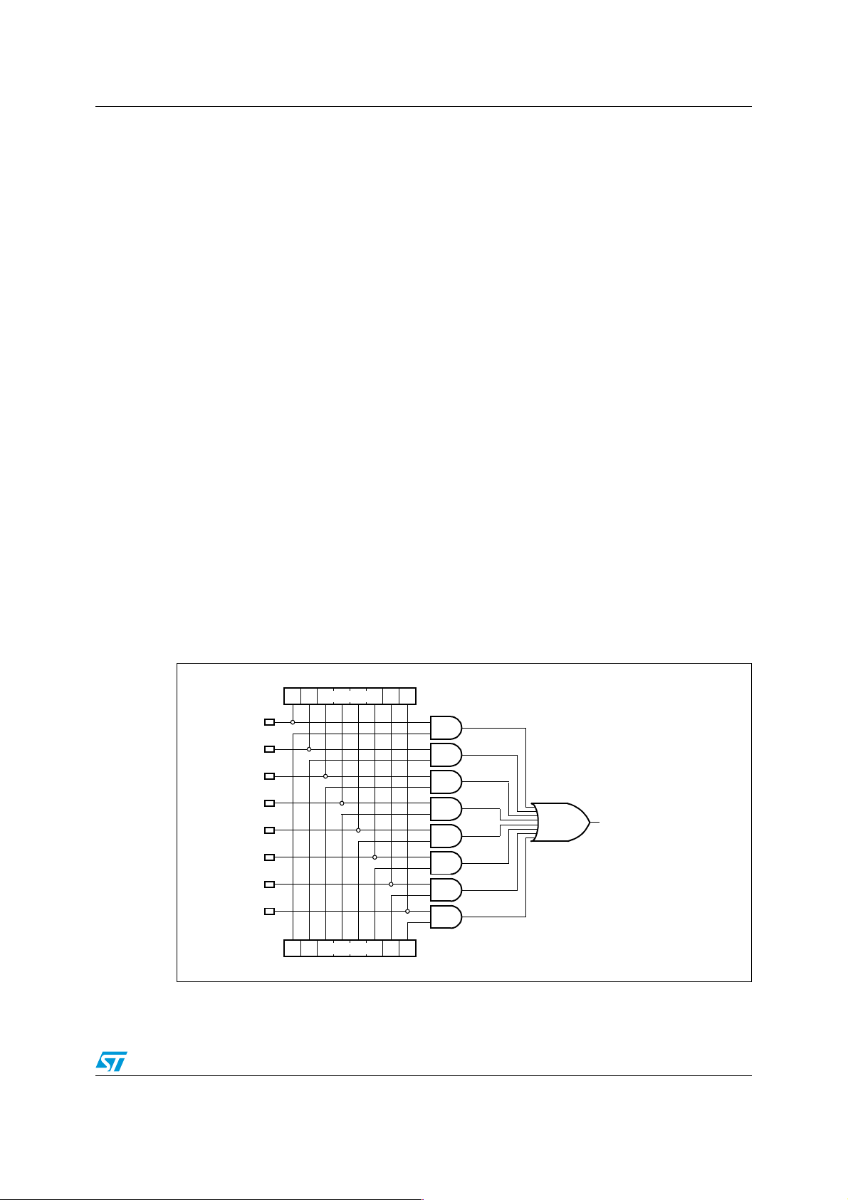
When different sources submit an interrupt request, the enable bits (Byte High of XIRxSEL
register) define a mask to select the sources to be associated with the unique available
vector. If more than one source is enabled to issue the request, the service routine must
identify the real event to be serviced. This can easily be done by checking the flag bits (Byte
Low of XIRxSEL register). Note that the flag bit provides information about events which are
not currently serviced by the interrupt controller (since masked through the enable bits),
allowing effective software management even when the related interrupt request cannot be
served: A periodic polling of the flag bits may be implemented inside the user application.
Global interrupt
.
Figure 1. X-Interrupt basic structure
70
Flag[7:0]
IT Source 7
IT Source 6
IT Source 5
IT Source 4
IT Source 3
IT Source 2
IT Source 1
IT Source 0
Enable[7:0]
15 8
XIRxSEL[7:0] (x = 0, 1, 2, 3)
XIRxSEL[15:8] (x = 0, 1, 2, 3)
3/26
XPxIC.IR (x = 0, 1, 2, 3)
Page 4

Interrupt sources and identification AN2341
In summary: To enable CAN interrupt to the CPU, set bit IE in the CAN control register,
corresponding enable bit in the XIRxSEL register (x = 0, 3 for CAN1, x = 1, 3 for CAN2) and
bit XPxIE in the X-peripherals interrupt control register XPxIC. Please refer to
Register descripti on
.
Appendix A:
1.2 Individual interrupt sources
The CAN controller distinguishes three different individual interrupt sources:
● Status interrupts
● Error interrupts
● Message-specific interrupts
1.2.1 Status interrupts
Status interrupts are generated after a status change of the CAN modules is indicated by
the flags in the status register. Status interrupts are enabled by setting bit SIE in the control
register.
Status interrupts are ca us ed by:
● Successful transmission from the CAN modules (TxOK is set) of any message from
message objects
● Reception of a message on the CAN bus - RxOK is set after an acknowledge of a CAN
frame from the CAN module - this CAN frame may not correspond to any message
object identifier.
● Occurrence of an error on the CAN bus during a message transfer (LEC bit field is
updated); this error may not come from the CAN module itself but has at least been
detected by the CAN modules. LEC code 7 is not used and may be written to 7 by the
CPU to check for updates.
TxOK, RxOK, LEC can be read from the status register.
Note: Enabling the Status Change Interrupt causes an interrupt to the CPU every time a message
is acknowledged on the CAN bus. For this reason, Status Change Interrupt should be
disabled in most applications except where a close monitor on the bus activity is required
(for example, after an early warning).
1.2.2 Error interrupts
Error Interrupts are generated once predefined error conditions are reached. Error interrupts
are enabled by setting bit EIE in the control register. Error interrupts are caused by:
● Warning status (EWarn is set) indicating that at least one of the error counters has
reached the error warning limit of 96
● Bus-off (BOff is set) indicating that the CAN controller is in bus-off state
EWarn and BOff can be read from the status register.
4/26
Page 5

AN2341 Interrupt sources and identification
1.2.3 Message-specific interrupts
Message-specific interrupts are generated by each message object. They are individually
enabled by setting bit TXIE (for transmission) or RXIE (for reception), or both, in the CAN
message objects.
Message-specific interrupts are caused by:
● Reception of a message (data frame or remote) into the corresponding message
object.
● Successful transmission (data frame or remote) of the corresponding message object.
Bit ‘IntPnd’ in each message object indicates that the corresponding message object has
generated an interrupt request.
Note: Refer to Section 2.1: Message-specific interrupts for further information on decoding
message-specific interrupts.
Identifying interrupt sources
The value of IntId code in the Interrupt register identifies the interrupt source; the Status
Interrupt has the highest priority. Among the message interrupts, the Message Object’s
interrupt priority decreases with increasing message number. A message interrupt is
cleared by clearing the Message Object’s IntPnd bit. The Status Interrupt is cleared by
reading the Status register.
● IntId = 0000h: Indicates that no (or no more) interrupt/s is/are pending.
● IntId = 0001h to 0020h: Indicate a Message-specific Reception or Transmission from
message object 1 to 32.
● IntId = 8000h: Indicates that a Status Change Interrupt or an Error Interrupt is pending.
5/26
Page 6

Handling interrupts AN2341
2 Handling interrupts
CAN interrupt-source priority decreases with increasing IntId code (except for Status
Change Interrupt). The IntId code is taken into account when identifying the interrupt
source. For example, if bits SIE and TXIE have been set, the successful transmission of a
message can cause two independent interrupt requests. While a status interrupt (highest
priority) is serviced, a message-specific interrupt remains pending (bit IntPnd of the
corresponding object is only cleared by writing a 0 value in the Message Object through
interface registers).
There are two ways to handle interrupts: One method relies on the hardwired priority of the
message object, the other method uses polling. These methods are described in
Programming through CAN hardware features on page 9
through polling on page 12
.
Although these two methods identify the interrupt source in different ways, they handle lower
level events in the same way. These lower level events are described in the following
sections.
2.1 Message-specific interrupts
and
Section 4: Programming
Section 3:
When a message object causes an interrupt, the message object can be identified in two
ways:
● From the IntId bit value
● By reading interrupt pending registers
The direction of bit DIR must be considered in the decoding phase:
Message objects with the message direction = ‘receive’ (bit DIR is reset)
These can be caused by:
● Successful transmission of a remote frame (TXIE must have been set)
● Successful reception of a data frame (RXIE must have been set)
The bit ‘NewDat’ can be used to differentiate between the two interrupt causes:
● NewDat = 1: Reception of a data frame
● NewDat = 0: Successful transmission of a remote frame
Message objects with message direction = ‘transmit’ (bit DIR is set)
These can be caused by:
● Reception of a remote frame with same identifier (RXIE must have been set)
● Successful transmission of a data frame following a CPU request or remote request
(TXIE must have been set)
Changing the message configuration
To change the message configuration during normal operation, set MsgVal to ‘not valid’ (bit
MsgVal = 0). When the new configuration is set into the message object registers, bit
MsgVal can be reset.
Example - software decoding of message-specific interrupts
6/26
Page 7

AN2341 Handling interrupts
Note: This example assumes that a ‘switch on IntId’ instruction is placed at the beginning of the
interrupt driver:
case (intid): // Message n specific interrupt
CANxIF1CM = 0x7F; // Transfer entire message into inference
CANxIF1CR = intid; // register and clear IntPnd and NewDat
CANx_WAIT_FOR_IF1;
if (CANxIF1A2 & IF_DIR) // direction = transmit
{
if (CANxIF1MC & IF_NEWDAT) // remote received provided that
// UMask =1 and RmtEn = 0
{.....} // procedure to handle answer to remote
else
{.....} // procedure to handle transmit interrupts
}
else // direction = receive
{
if (CANxIF1MC & IF_NEWDAT) // NewDat is set
{.....} // procedure to handle data receive interrupt
else
{.....} // a remote frame was successfully transmitted
}
break;
2.2 Bus-off interrupts
Each transfer error detected on the CAN bus (though not necessarily generated by the CAN
module) increments one of the two error counters (receive error counter and transmit error
counter). If one of these counters reaches the value of 96, bit EWarn is set. If enabled by
bits EIE and IE, an error interrupt is generated. If the transmit error counter exceeds the
value of 255, bit BOff is set. If enabled by bits EIE and IE, this generates an error interrupt.
Furthermore, when the device goes into the bus-off state, bit INIT is set and all actions on
the bus are stopped immediately.
The bus-off recovery sequence can be initiated from the bus-off state. During the bus
recovery sequence, the CAN module monitors the recovery sequence.
● The bus-off recovery sequence is started by resetting bit INIT.
● Bit0Error is set every time a sequence of 11 recessive bits is detected. Bit0Error
indicates that the CAN bus is not stuck at dominant or not continuously disturbed. If bits
SIE and IE are set, a status interrupt is generated after each sequence.
● The recovery sequence cannot be shortened by setting or resetting bit INIT.
7/26
Page 8

Handling interrupts AN2341
case 0x8000: // IntId=0x8000 for status and error interrupt
{
if (CANxCR & EIE) // error interrupt are enabled
{
if (CANxSR & EWRN) // EWarn is set
{ ......} // procedure for Early warning
if (CANxSR & BOFF) // BOff is set
{ .......} // bus-off procedure
}
break;
8/26
Page 9

AN2341 Programming through CAN hardware features
3 Programming through CAN hardware features
Programming the CAN interrupt drivers through CAN hardware features uses bits RXIE and
TXIE in the message control register of each message object. Whenever a message is
transmitted or received by a message object, the corresponding interrupt is serviced
according to its priority (based on the value of IntId). This method uses the hardwired priority
scheme of the CAN module and requires minimum CPU overhead. This section provides a
sample program for programming through CAN hardware features.
Hints:
● If the Status Change Interrupt is enabled, the CPU is interrupted every time a message
is acknowledged on the CAN bus. Disable the Status Change Interrupt!
● RXOK is cleared by the Status Change Interrupt routine. Therefore, do not use RXOK
to identify the cause of interrupts.
● TXOK can be used to identify the cause of an interrupt if the Status Change Interrupt is
disabled and if TXOK is cleared by every interrupt routine of message objects with
direction = ‘transmit’. For clarity, the example below assumes that Status Change
Interrupt is enabled.
● There are two ways to use the sample program provided below:
– The software interrupt driver repeats itself as long as there is an active interrupt in
the CAN module.
– The software driver is run once and handles only one interrupt. This allows the
interrupt controller to re-arbitrate interrupts of the same priority level but not of a
higher priority group.
// CAN interrupt driver
include <REGF2xxx.h> // standard include file for F27x/F25x
#include "CCAN_drvs.h" // inc file to define bit masks and macro
// see Section 6 for description.
interrupt(0x4x) void CAN_IT (void)
// CAN Module IR, trap number 0x40, 0x41, 0x43,
// according to user choice, see
Section 1.1
{
XIRxCLR = 0xXX; //flag to be cleared according to user choice
//see
Section 1.1
unsigned char status, intid, control;
while (intid=CANxIR) //reload intid with CANxIR,
// continue loop if intid != 0
//‘while’can be removed to run IT driver once
{
status = CANxSR;// copy status + control REG to variable
control = CANxCR;
CANxSR=0; // clear status register
switch (intid)
{
case 0x8000: // Status Change Interrupt
if (CANxCR & SIE)// if SIE is set (status interrupts)
{
9/26
Page 10

Programming through CAN hardware features AN2341
if (status & TxOK)
{......}
// transmit interrupt
if (status & RxOK)
{......}
// receive interrupt
if (status & 0x07)
{......}
// erroneous transfer interrupt
}
if (CANxCR & EIE) // if EIE is set (error interrupts)
{
if (status & EWRN)
{......}
// error counter warning
if (status & BOFF) // bus-off situation
CANxCR = (CANxCR & 0xfe);
// recover from BOff (clear INIT)
{......} // remaining part of the BOff procedure
}
break;
case 1: // Message 1 Interrupt
CANxIF1CM = 0x7F;
// Transfer entire message into inference
CANxIF1CR = intid;
// register and clear IntPnd and NewDat
CANx_WAIT_FOR_IF1;
if (CANxIF1A2 & IF_DIR) // direction = transmit
{
if (CANxIF1MC & IF_NEWDAT)
// remote received provided that UMask = 1
// and RmtEn = 0
{.....} // procedure to handle answer to remote
else
{.....} // procedure to handle transmit interrupts
}
else // direction = receive
{
if (CANxIF1MC & IF_NEWDAT) // NewDat is set
{.....}
// procedure to handle data receive interrupt
else
{.....} // a remote frame was successfully transmitted
}
break;
block to be repeated (from ‘case 1:’ to ‘case 32:’)
case n: // Message n Interrupt
CANxIF1CM = 0x7F;
// Transfer entire message into inference
CANxIF1CR = intid;
// register and clear IntPnd and NewDat
10/26
Page 11

AN2341 Programming through CAN hardware features
CANx_WAIT_FOR_IF1;
if (CANxIF1A2 & IF_DIR) // direction = transmit
{
if (CANxIF1MC & IF_NEWDAT)
// remote received provided that UMask = 1
// and RmtEn = 0
{.....} // procedure to handle answer to remote
else
{.....} // procedure to handle transmit interrupts
}
else // direction = receive
{
if (CANxIF1MC & IF_NEWDAT) // NewDat is set
{.....}
// procedure to handle data receive interrupt
else
{.....} // a remote frame was successfully transmitted
}
break;
}
}
}
11/26
Page 12

Programming through polling AN2341
4 Programming through polling
Programming the interrupt driver using polling generates an interrupt whenever a successful
transmission or reception occurs. This is done by setting bit SIE of the control register.
RXOK or TXOK is (or both are) set when a message object transmits or receives a
message.
The CAN module sets RXOK whenever a message is acknowledged on the CAN bus.
Once in the interrupt routine, the CPU polls bit IntPnd of each message object. The
message object polling sequence defines the message object priority, independent of the
existing hardware priority scheme defined for IntId.
Polling is high in the CPU overhead as the CPU is interrupted every time a message is
acknowledged on the CAN bus. Therefore, programming the interrupt driver using polling is
recommended for small networks only.
This section provides a sample program for programming through polling.
// CAN interrupt driver
//
include <REGF2xxx.h> // standard include file for F27x/F25x
#include "CCAN_drvs.h" // inc file to define bit masks and macro
// see Section 6 for description.
interrupt(0x4x) // CAN Module IR, trap number 0x40, 0x41, 0x43,
void CAN_IT (void)// according to user choice see
{
unsigned short i;
unsigned char status, control;
{
status = CANxSR;// copy status + control REG to variable
control = CANxCR;
CANxSR=0; // clear status register
XIRxCLR = 0xXX; //flag to be cleared according to user choice
//see
CANxIF1CM = 0x7F; // Transfer entire message into interface
CANxIF1CR = 1; // register and clear IntPnd and NewDat
CANx_WAIT_FOR_IF1;
if (CANxIF1MC & IF_INTPND)
{.....} // procedure to handle message 1 interrupts
Section 1.1
Section 1.1
....
CANxIF1CM = 0x7F; // Transfer entire message into inference
CANxIF1CR = 32; // register and clear IntPnd and NewDat
CANx_WAIT_FOR_IF1;
if (CANxIF1MC & IF_INTPND)
{.....} // procedure to handle message 32 interrupts
}
12/26
Page 13

AN2341 Programming through polling
Then, for each message object, the procedure to handle interrupt and decode can be the
same as the one proposed before:
if (CANxIF1A2 & IF_DIR) // direction = transmit
{
if (CANxIF1MC & IF_NEWDAT) // remote received
//provided that UMask = 1 and RmtEn = 0
{.....} // procedure to handle answer to remote
else
{.....} // procedure to handle transmit interrupts
}
else // direction = receive
{
if (CANxIF1MC & IF_NEWDAT) // NewDat is set
{.....} // procedure to handle data receive interrupt
else
{.....} // a remote frame was successfully transmitted
}
break;
13/26
Page 14

Register description AN2341
Appendix A Register description
A.1 Global interrupt control registers
XP0IC (F186h / C3h) ESFR Reset Value: --00h
1514131211109876543210
- - - - - - - - XP0IR XP0IE ILVL GLVL
RW RW RW RW
XP1IC (F18Eh / C7h) ESFR Reset Value: - - 00h
1514131211109876543210
--------
XP3IC (F19Eh / CFh) ESFR Reset Value: - - 00h
1514131211109876543210
- - - - - - - - XP3IR XP3IE ILVL GLVL
XIR0SEL (EB10h) XBUS Reset Value: 0000h
XP1IR XP1IE ILVL GLVL
RW RW RW RW
RW RW RW RW
1514131211109876543210
IE.7 IE.6 IE.5 IE.4 IE.3 IE.2 IE.1 IE.0 FL.7 FL.6 FL.5 FL.4 FL.3 FL.2 FL.1 FL.0
RW RW RW RW RW RW RW RW RW RW RW RW RW RW RW RW
Table 1. XIR0SEL register
Bit Function
Interrupt flag 0: CAN1 interrupt
FL.0
‘0’: No interrupt request.
‘1’: Interrupt request pending.
2
C transmit
FL.1
Interrupt flag 1: I
‘0’: No interrupt request.
‘1’: Interrupt request pending.
Interrupt flag 2: I2C receive
FL.2
‘0’: No interrupt request.
‘1’: Interrupt request pending.
Interrupt flag 0: XSSC transmit
FL.3
‘0’: No interrupt request.
‘1’: Interrupt request pending.
Interrupt flag 4: XSSC receive
FL.4
‘0’: No interrupt request.
‘1’: Interrupt request pending.
14/26
Page 15

AN2341 Register description
Table 1. XIR0SEL register (continued)
Bit Function
Interrupt flag 5: XASC transmit buffer
FL.5
FL.6
FL.7
IE.0
IE.1
IE.2
‘0’: No interrupt request.
‘1’: Interrupt request pending.
Interrupt flag 6: XASC transmit
‘0’: No interrupt request.
‘1’: Interrupt request pending.
Interrupt flag 7: XASC receive
‘0’: No interrupt request.
‘1’: Interrupt request pending.
Interrupt enable 0: CAN1 interrupt
‘0’: Interrupt request disabled.
‘1’: Interrupt request enabled.
2
Interrupt enable 1: I
C transmit
‘0’: Interrupt request disabled.
‘1’: Interrupt request enabled.
2
Interrupt enable 2: I
C receive
‘0’: Interrupt request disabled.
‘1’: Interrupt request enabled.
IE.3
IE.4
IE.5
IE.6
IE.7
Interrupt enable 3: XSSC transmit
‘0’: Interrupt request disabled.
‘1’: Interrupt request enabled.
Interrupt enable 4: XSSC receive
‘0’: Interrupt request disabled.
‘1’: Interrupt request enabled.
Interrupt enable 5: XASC transmit buffer
‘0’: Interrupt request disabled.
‘1’: Interrupt request enabled.
Interrupt enable 6: XASC transmit
‘0’: Interrupt request disabled.
‘1’: Interrupt request enabled.
Interrupt enable 7: XASC receive
‘0’: Interrupt request disabled.
‘1’: Interrupt request enabled.
15/26
Page 16

Register description AN2341
XIR1SEL (EB20h) XBUS Reset Value: 0000h
1514131211109876543210
IE.7 IE.6 IE.5 IE.4 IE.3 IE.2 IE.1 IE.0 FL.7 FL.6 FL.5 FL.4 FL.3 FL.2 FL.1 FL.0
RW RW RW RW RW RW RW RW RW RW RW RW RW RW RW RW
Table 2. XIR1SEL register
Bit Function
Interrupt flag 0: CAN2 interrupt
FL.0
FL.1
FL.2
FL.3
‘0’: No interrupt request.
‘1’: Interrupt request pending.
2
Interrupt flag 1: I
C transmit
‘0’: No interrupt request.
‘1’: Interrupt request pending.
2
Interrupt flag 2: I
C receive
‘0’: No interrupt request.
‘1’: Interrupt request pending.
Interrupt flag 0: XSSC transmit
‘0’: No interrupt request.
‘1’: Interrupt request pending.
FL.4
FL.5
FL.6
FL.7
IE.0
IE.1
IE.2
IE.3
Interrupt flag 4: XSSC receive
‘0’: No interrupt request.
‘1’: Interrupt request pending.
Interrupt flag 5: XASC transmit buffer
‘0’: No interrupt request.
‘1’: Interrupt request pending.
Interrupt flag 6: XASC transmit
‘0’: No interrupt request.
‘1’: Interrupt request pending.
Interrupt flag 7: XASC receive
‘0’: No interrupt request.
‘1’: Interrupt request pending.
Interrupt enable 0: CAN2 Interrupt
‘0’: Interrupt request disab led .
‘1’: Interrupt request enable d.
2
Interrupt enable 1: I
C transmit
‘0’: Interrupt request disab led .
‘1’: Interrupt request enable d.
2
Interrupt enable 2: I
C receive
‘0’: Interrupt request disab led .
‘1’: Interrupt request enable d.
Interrupt enable 3: XSSC transmit
‘0’: Interrupt request disab led .
‘1’: Interrupt request enable d.
16/26
Page 17

AN2341 Register description
Table 2. XIR1SEL register (continued)
Bit Function
Interrupt enable 4: XSSC receive
IE.4
IE.5
IE.6
IE.7
XIR3SEL (EB40h) XBUS Reset Value: 0000h
1514131211109876543210
IE.7 IE.6 IE.5 IE.4 IE.3 IE.2 IE.1 IE.0 FL.7 FL.6 FL.5 FL.4 FL.3 FL.2 FL.1 FL.0
RW RW RW RW RW RW RW RW RW RW RW RW RW RW RW RW
Table 3. XIR3SEL register
‘0’: Interrupt request disab led .
‘1’: Interrupt request enable d.
Interrupt enable 5: XASC transmit buffer
‘0’: Interrupt request disab led .
‘1’: Interrupt request enable d.
Interrupt enable 6: XASC transmit
‘0’: Interrupt request disab led .
‘1’: Interrupt request enable d.
Interrupt enable 7: XASC receive
‘0’: Interrupt request disab led .
‘1’: Interrupt request enable d.
Bit Function
Interrupt flag 0: CAN1 interrupt
FL.0
‘0’: No interrupt request.
‘1’: Interrupt request pending.
Interrupt flag 1: CAN2 interrupt
FL.1
‘0’: No interrupt request.
‘1’: Interrupt request pending.
2
C error
FL.2
Interrupt flag 2: I
‘0’: No interrupt request.
‘1’: Interrupt request pending.
Interrupt flag 0: XSSC error
FL.3
‘0’: No interrupt request.
‘1’: Interrupt request pending.
Interrupt flag 4: XASC error
FL.4
‘0’: No interrupt request.
‘1’: Interrupt request pending.
Interrupt flag 5: PLL unlock / oscillator watchdog
FL.5
‘0’: No interrupt request.
‘1’: Interrupt request pending.
channel 3...0
FL.6
Interrupt flag 6: XPWM
‘0’: No interrupt request.
‘1’: Interrupt request pending.
FL.7 Interrupt flag 7:
No interrupt source associated.
17/26
Page 18

Register description AN2341
Table 3. XIR3SEL register (continued)
Bit Function
Interrupt enable 0: CAN1 interrupt
IE.0
IE.1
IE.2
IE.3
IE.4
IE.5
‘0’: Interrupt request disab led .
‘1’: Interrupt request enable d.
Interrupt enable 1: CAN2 interrupt
‘0’: Interrupt request disab led .
‘1’: Interrupt request enable d.
2
Interrupt enable 2: I
‘0’: Interrupt request disab led .
‘1’: Interrupt request enable d.
Interrupt enable 3: XSSC error
‘0’: Interrupt request disab led .
‘1’: Interrupt request enable d.
Interrupt enable 4: XASC error
‘0’: Interrupt request disab led .
‘1’: Interrupt request enable d.
Interrupt enable 5: PLL unlock / oscillator watchdog
‘0’: Interrupt request disab led .
‘1’: Interrupt request enable d.
C error
Interrupt enable 6: XPWM channel 3...0
IE.6
IE.7 Interrupt enable 7: No interrupt source associated.
‘0’: Interrupt request disab led .
‘1’: Interrupt request enable d.
18/26
Page 19

AN2341 Register description
A.2 CAN control register
CAN1CR (EF00h),
CAN2CR (EE00h)
1514131211109876543210
--------TestCCEDAR-EIESIEIEInit
Table 4. CAN1CR and CAN2CR registers
Bit Function
Initialization
Init
’0’: Normal operation.
’1’: Initialization is started.
Module interrupt enable
IE
’0’: Disabled - Module interrupt IRQ_B is always high.
’1’: Enabled - Interrupts wil l set IRQ_B to LOW. IRQ_B remains low unt il a ll pending
interrupts are processed.
Status change interrupt enable
SIE
’0’: Disabled - No Status Change Interrupt will be generated.
’1’: Enabled - An int errupt will be gene rated wh en a mess age trans fe r is success fully
completed or a CAN bus error is detected.
XBUS Reset Value: 0001h
RW RW RW RW RW RW RW
EIE
DAR
CCE
Test
Error interrupt enable
‘0’: Disabled - No error status interrupt will be generated.
‘1’: Enabled - A change in t he bits BOff or EWarn in the status register wil l gen erate
an interrupt.
Disable automatic retr ans mi ss ion
‘0’: Automatic retransmission of disturbed messages enabled.
‘1’: Automatic retransmission disabled.
Configuration change enable
‘0’: The CPU has no write access to the bit timing register.
one
‘1’: The CPU has write access to the Bit Timing register (while Init =
).
Test mode enable
‘0’: Normal operation.
‘1’: Test mode.
19/26
Page 20

Register description AN2341
A.3 CAN status register
CAN1SR (EF02h),
CAN2SR (EE02h)
1514131211109876543210
--------
Table 5. CAN1SR and CAN2SR registers
Bit Function
Last error code (Type of the last error to occur on the CAN bus)
’000’: No error.
’001’: Stuff Error: More than 5 equal bits in a sequ ence ha ve occurred in a part of a
received message where this is not allowed.
’010’: Form Error: A fixed format part of a received frame has the wrong format.
’011’: AckError: T he messag e this CAN Core tr ansmitted was not ackno wle dged by
another node.
’100’: Bit1Error: During the transmission of a message (with the exception of the
arbitration field), the device wanted to send a
but the monitored bus value was
LEC
’101’: Bit0Error: During the transmission of a message (or acknowledge bit, or
active error flag, or overload flag), the device wanted to send a
or identifier bit logical value ‘0’), but the monitored Bus value was
bus-off
recovery this status is set each time a sequence of 11
been monitored. This enables the CPU to monitor the progression of the bus-off
recovery sequence (indicating the bus is not stuck at
disturbed).
’110’: CRCError: The CRC check sum was incorrect in the message received, the
CRC received for an incoming message does not ma tch w ith the calc ulated CRC f or
the received data.
’111’: Unused. When the LEC shows the value ‘7’, no CAN bus event was detected
since the CPU wrote this value to the LEC.
XBUS Reset Value: 0000h
BOff EWarn EPass RxOk TxOk LEC
RRRRWRW RW
dominant
recessive
.
level (bi t of logic al va lu e ‘1’),
dominant
dominant
recessive
or continuously
leve l (dat a
recessive
bits has
. During
Transmitted a message successfully
’0’: Since this bit was reset by the CPU, no message has been successfully
TxOk
transmitted. This bit is never reset by the CAN Core.
’1’: Since this bit w as la st rese t b y the CPU, a message has been succ essf ully (e rror
free and acknowledged by at least one other node) transmitted.
Received a message successfully
’0’: Since this bit was last reset by the CPU, no message has been successfully
RxOk
received. This bit is never reset by the CAN Core.
’1’: Since this bit was last reset (to zero) by the CPU, a message has been
successfully received (independent of the result of acceptance filtering).
Error passive
EPass
‘0’: The CAN Core is
error active
‘1’: The CAN Core is in the
20/26
.
error passive
state as defined in the CAN Specification.
Page 21

AN2341 Register description
Table 5. CAN1SR and CAN2SR registers (continued)
Bit Function
Warning status
EWarn
BOff
‘0’: Both error counters are below the error warning limit of 96.
‘1’: At least one of the error counte rs in the EM L has rea che d the error w arning li mi t
of 96.
Bus-off status
‘0’: The CAN module is not bus-off.
‘1’: The CAN module is in bus-off state.
21/26
Page 22

Message object register definition AN2341
Appendix B Message object register definition
B.1 CCAN_drvs.h
/******************************************************************
************/
// CAN Cell Base Addresses
/******************************************************************
************/
#define CAN1 (unsigned int*)0xEF00
#define CAN2 (unsigned int*)0xEE00
/******************************************************************
************/
// CAN register Offsets
// Since these are offsets to a pointer of type (unsigned int*)
// Tasking requires that they be in WORD values, or else the
compiler doubles them
/******************************************************************
**/
#define CAN_CR 0x0000 // 0x0000 Control Register
#define CAN_SR 0x0001 // 0x0002 Status Register
#define CAN_EC 0x0002 // 0x0004 Error Counter Register
#define CAN_BTR 0x0003 // 0x0006 Bit Timing Register
#define CAN_IR 0x0004 // 0x0008 Interrupt Register
#define CAN_TR 0x0005 // 0x000A Test Register
#define CAN_BRPER 0x0006 // 0x000C BRP Extension Register
#define CAN_IF1_CR 0x0008 // 0x0010 Command Request Register
#define CAN_IF1_CM 0x0009 // 0x0012 Command Mask Register
#define CAN_IF1_M1 0x000A // 0x0014 Mask 1 Register
#define CAN_IF1_M2 0x000B // 0x0016 Mask 2 Register
#define CAN_IF1_A1 0x000C // 0x0018 Arbitration 1 Register
#define CAN_IF1_A2 0x000D // 0x001A Arbitration 2 Register
#define CAN_IF1_MC 0x000E // 0x001C Message Control Register
#define CAN_IF1_DA1 0x000F // 0x001E Data A1 Register
#define CAN_IF1_DA2 0x0010 // 0x0020 Data A2 Register
#define CAN_IF1_DB1 0x0011 // 0x0022 Data B1 Register
#define CAN_IF1_DB2 0x0012 // 0x0024 Data B2 Register
#define CAN_IF2_CR 0x0020 // 0x0040 Command Request Register
#define CAN_IF2_CM 0x0021 // 0x0042 Command Mask Register
#define CAN_IF2_M1 0x0022 // 0x0044 Mask 1 Register
#define CAN_IF2_M2 0x0023 // 0x0046 Mask 2 Register
#define CAN_IF2_A1 0x0024 // 0x0048 Arbitration 1 Register
#define CAN_IF2_A2 0x0025 // 0x004A Arbitration 2 Register
#define CAN_IF2_MC 0x0026 // 0x004C Message Control Register
#define CAN_IF2_DA1 0x0027 // 0x004E Data A1 Register
#define CAN_IF2_DA2 0x0028 // 0x0050 Data A2 Register
#define CAN_IF2_DB1 0x0029 // 0x0052 Data B1 Register
#define CAN_IF2_DB2 0x002A // 0x0054 Data B2 Register
#define CAN_TR1 0x0040 // 0x0080 Transmit Request 1 Register
#define CAN_TR2 0x0041 // 0x0082 Transmit Request 2 Register
22/26
Page 23

AN2341 Message object register definition
#define CAN_ND1 0x0048 // 0x0090 New Data 1 Register
#define CAN_ND2 0x0049 // 0x0092 New Data 2 Register
#define CAN_IP1 0x0050 // 0x00A0 Interrupt Pending 1 Register
#define CAN_IP2 0x0051 // 0x00A0 Interrupt Pending 1 Register
#define CAN_MV1 0x0058 // 0x00B0 Message Valid 1 Register
#define CAN_MV2 0x0059 // 0x00B2 Message Valid 2 Register
// Control Register Bits
#define INIT 0x0001 // Initialization Enable
#define IE 0x0002 // Interrupt Enable
#define SIE 0x0004 // Status Interrupt Enable
#define EIE 0x0008 // Error Interrupt Enable
#define DAR 0x0020 // Disable Auto Retransmission
#define CCE 0x0040 // Configuration Change Enable
#define TST 0x0080 // Test Mode
// Status Register Bits
#define TXOK 0x0008 // Message Transmitted OK
#define RXOK 0x0010 // Message Received OK
#define EPASS 0x0020 // Error Passive
#define EWRN 0x0040 // Error Warning
#define BOFF 0x0080 // Buss Off
// Interrupt Register Bits
#define RP 0x8000 // Receive Error Passive
// Command Register Bits
#define IF_BUSY 0x8000
// Command Mask Register Bits
#define IF_DATA_B 0x0001
#define IF_DATA_A 0x0002
#define IF_TXR_ND 0x0004
#define IF_CLR_IP 0x0008
#define IF_CNTRL 0x0010
#define IF_ARB 0x0020
#define IF_MASK 0x0040
#define IF_WRRD 0x0080
// Mask Register Bits
#define IF_MXTD 0x8000
#define IF_MDIR 0x4000
// Arbitration Register Bits
#define IF_MSGVAL 0x8000
#define IF_XTD 0x4000
#define IF_DIR 0x2000
// Message Control Register Bits
#define IF_NEWDAT 0x8000
#define IF_MSGLST 0x4000
#define IF_INTPND 0x2000
#define IF_UMASK 0x1000
#define IF_TXIE 0x0800
#define IF_RXIE 0x0400
#define IF_RMTEN 0x0200
23/26
Page 24

Message object register definition AN2341
#define IF_TXRQST 0x0100
#define IF_EOB 0x0080
/******************************************************************
************/
// Some Status Definitions
/******************************************************************
************/
#define CAN_RCV_OK 0x0000
#define CAN_RCV_TIMEOUT 0x0001
#define NO_STATUS_CHANGE 0xFFFF
#define CAN_TX_TIMEOUT 0x8000
#define CAN_TX_OK 0x0000
/******************************************************************
************/
// Some useful BTR numbers
/******************************************************************
************/
#define BTR_40MHZ_500KB 0x2542
#define BTR_40MHZ_1MB 0x2541
/******************************************************************
************/
// Useful Macros
/******************************************************************
************/
//unsigned int* CANBlock;
#define CAN1_WAIT_FOR_IF1 while( *(CAN1 + CAN_IF1_CR) & IF_BUSY )
#define CAN1_WAIT_FOR_IF2 while( *(CAN1 + CAN_IF2_CR) & IF_BUSY )
#define CAN2_WAIT_FOR_IF1 while( *(CAN2 + CAN_IF1_CR) & IF_BUSY )
#define CAN2_WAIT_FOR_IF2 while( *(CAN2 + CAN_IF2_CR) & IF_BUSY )
Note: All software provided here follows the TASKING CAN library register naming convention.
Register naming may be different for another tool chain.
24/26
Page 25

AN2341 Revision history
5 Revision history
Table 6. Document revision history
Date Revision Changes
19-May-2006 1 Initial release.
25/26
Page 26

AN2341
Please Read Carefully:
Information in this document is provided sole ly in connecti on with ST produ cts. STMicro electroni cs NV and its subsi diaries (“ST ”) reserve the
right to make changes , cor recti ons , modif ic ations or improv ement s, t o th is documen t, and the prod ucts an d servic es des crib ed he rein a t any
time, without notice.
All ST products are sold pursuant to ST’s terms and conditions of sale.
Purchasers are solely responsible for the choice, selection and use of the ST products and services described herein, and ST assumes no
liability whatsoever relating to the choice, selectio n or use of the ST products and services described herein.
No license, express or implied, by estoppel or otherwise, to any intellectual property rights is granted under this document. If any part of this
document refers to any third party products or services it shall not be deemed a license grant by ST for the use of such third party products
or services, or any intellectual property contained therein or considered as a warranty covering the use in any manner whatsoever of such
third party produc ts or services or any intellectual property contained therein.
UNLESS OTHERWISE SET FORTH IN ST’S TERMS AND CONDITIONS OF SALE ST DISCLAIMS ANY EXPRESS OR IMPLIED
WARRANTY WITH RESPECT TO THE USE AND/OR SALE OF ST PRODUCTS INCLUDING WITHOUT LIMITATION IMPLIED
WARRANTIES OF MERCHANTABILITY, FITNESS FOR A PARTICULAR PURPOSE (AND THEIR EQUIVALENTS UNDER THE LAWS
OF ANY JURISDICTION), OR INFRINGEMENT OF ANY PATENT, COPYRIGHT OR OTHER INTELLECTUAL PROPERTY RIGHT.
UNLESS EXPRESSLY APPROVED IN WRITING BY AN AUTHORIZE REPRESENTATIVE OF ST, ST PRODUCTS ARE NOT DESIGNED,
AUTHORIZED OR WARRANTED FOR USE IN MILITARY, AIR CRAFT, SPACE, LIFE SAVING, OR LIFE SUSTAINING APPLICATIONS,
NOR IN PRODUCTS OR SYSTEMS, WHERE FAILURE OR MALFUNCTION MAY RESULT IN PERSONAL INJURY, DEATH, OR
SEVERE PROPERTY OR ENVIRONMENTAL DAMAGE.
Resale of ST products with prov isions differen t from the state ments and/or tec hnical featur es set forth in th is document shall immediatel y void
any warranty granted by ST for the ST product or service described herein and shall not create or extend in any manner whatsoever, any
liability of ST.
ST and the ST logo are trademark s or registered trademarks of ST in various countries.
Information in this document su persedes and replaces all information previously supplied.
The ST logo is a registered trade mark of STMicroelectronics. All other names are the property of their respective owners.
© 2006 STMicroelectronics - All rights reserv ed
STMicroelectronics group of companies
Australia - Belgium - Brazil - Canada - China - Czech Republic - Finland - France - Germany - Hong Kong - India - Israel - Italy - Japan -
Malaysia - Malta - Morocco - Singapore - Spain - Sweden - Switzerland - United Kingdom - United States of America
www.st.com
26/26
 Loading...