

Page 1

AN2288
Application note
Single-phase energy meter with tamper detection
based on ST7FLITE2x
Introduction
This application note describes the design for a single-phase power / energy meter with
tamper detection. The design measures active power, voltage, current, power factor and line
frequency in a single-phase distribution environment and displays active energy, voltage,
current, power factor, line frequency, current date and time. It differs from ordinary singlephase meters in that it uses two current transformers (CT) to measure active power in both
live and neutral wires. This enables the meter to detect, signal, and continue to measure the
active energy consumed reliably even when subject to external tamper attempts.
ST7FLITE20 is the microcontroller used to perform all the measurements in the meter. As
the ST7FLITE30 is pin-to-pin compatible with ST7FLITE20, the ST7LITE30 can also be
used in this application (replacing the ST7LITE20) but a revalidation is required for finding
the accuracy class of the meter.
The active energy consumed is available in the form of frequency-modulated pulse outputs
and the accumulated active energy on an LCD display module. Additional features for both
consumer types can also be incorporated. These include multiple tariff rates and improved
communications, through which meter readings can be taken with less time and with higher
accuracy.
May 2006 Rev 1 1/29
www.st.com
Page 2

Contents AN2288
Contents
1 Features . . . . . . . . . . . . . . . . . . . . . . . . . . . . . . . . . . . . . . . . . . . . . . . . . . . 4
2 Overview . . . . . . . . . . . . . . . . . . . . . . . . . . . . . . . . . . . . . . . . . . . . . . . . . . 5
3 Theory . . . . . . . . . . . . . . . . . . . . . . . . . . . . . . . . . . . . . . . . . . . . . . . . . . . . 6
3.1 Analog front end . . . . . . . . . . . . . . . . . . . . . . . . . . . . . . . . . . . . . . . . . . . . . 7
4 Meter hardware . . . . . . . . . . . . . . . . . . . . . . . . . . . . . . . . . . . . . . . . . . . . . 9
4.1 Main blocks . . . . . . . . . . . . . . . . . . . . . . . . . . . . . . . . . . . . . . . . . . . . . . . 10
4.1.1 5V power supply block . . . . . . . . . . . . . . . . . . . . . . . . . . . . . . . . . . . . . . 10
4.1.2 2.5V reference block . . . . . . . . . . . . . . . . . . . . . . . . . . . . . . . . . . . . . . . 10
4.1.3 Current transformer block . . . . . . . . . . . . . . . . . . . . . . . . . . . . . . . . . . . 11
4.1.4 Voltage divider block . . . . . . . . . . . . . . . . . . . . . . . . . . . . . . . . . . . . . . . 11
4.1.5 Tamper detection block . . . . . . . . . . . . . . . . . . . . . . . . . . . . . . . . . . . . . 12
4.1.6 Gain switching block . . . . . . . . . . . . . . . . . . . . . . . . . . . . . . . . . . . . . . . 12
4.1.7 EEPROM block . . . . . . . . . . . . . . . . . . . . . . . . . . . . . . . . . . . . . . . . . . . 14
4.1.8 RTC block . . . . . . . . . . . . . . . . . . . . . . . . . . . . . . . . . . . . . . . . . . . . . . . 15
4.1.9 LCD module . . . . . . . . . . . . . . . . . . . . . . . . . . . . . . . . . . . . . . . . . . . . . . 15
4.1.10 In-Circuit Programming block . . . . . . . . . . . . . . . . . . . . . . . . . . . . . . . . . 16
4.1.11 Calibration through PC GUI . . . . . . . . . . . . . . . . . . . . . . . . . . . . . . . . . . 17
4.1.12 Microcontroller block . . . . . . . . . . . . . . . . . . . . . . . . . . . . . . . . . . . . . . . 17
5 Software routines . . . . . . . . . . . . . . . . . . . . . . . . . . . . . . . . . . . . . . . . . . 18
5.1 Initialization routine . . . . . . . . . . . . . . . . . . . . . . . . . . . . . . . . . . . . . . . . . . 18
5.2 Main routine . . . . . . . . . . . . . . . . . . . . . . . . . . . . . . . . . . . . . . . . . . . . . . . 18
5.3 Lite timer time base2 interrupt routine . . . . . . . . . . . . . . . . . . . . . . . . . . . 20
5.4 SPI interrupt routine . . . . . . . . . . . . . . . . . . . . . . . . . . . . . . . . . . . . . . . . . 22
5.5 AVD interrupt routine . . . . . . . . . . . . . . . . . . . . . . . . . . . . . . . . . . . . . . . . 23
5.6 External interrupt routine . . . . . . . . . . . . . . . . . . . . . . . . . . . . . . . . . . . . . 23
5.7 ART timer input capture interrupt routine . . . . . . . . . . . . . . . . . . . . . . . . . 23
6 Results . . . . . . . . . . . . . . . . . . . . . . . . . . . . . . . . . . . . . . . . . . . . . . . . . . . 24
6.1 Load tests . . . . . . . . . . . . . . . . . . . . . . . . . . . . . . . . . . . . . . . . . . . . . . . . . 24
6.2 Voltage tests . . . . . . . . . . . . . . . . . . . . . . . . . . . . . . . . . . . . . . . . . . . . . . . 25
2/29
Page 3

AN2288 Contents
6.3 Frequency tests . . . . . . . . . . . . . . . . . . . . . . . . . . . . . . . . . . . . . . . . . . . . 25
7 Conclusions . . . . . . . . . . . . . . . . . . . . . . . . . . . . . . . . . . . . . . . . . . . . . . . 26
8 Calibration coefficients . . . . . . . . . . . . . . . . . . . . . . . . . . . . . . . . . . . . . . 27
9 Revision history . . . . . . . . . . . . . . . . . . . . . . . . . . . . . . . . . . . . . . . . . . . 28
3/29
Page 4

Features AN2288
1 Features
● Cost-Effective and Flexible Single-Phase Energy Meter
● ASSP is not used; microcontroller is doing all the measurements and calculations
● Fulfils IEC 61036:1996 + A1: 2000, Static meter for active energy (classes 1 and 2) for
Ib=10A and Imax=55A
● Meter starts at few mA
● Detects, Signals and Continues to Measure Accurately under tamper Condition
● Compact design with Internal Flash memory, SRAM and external EEPROM
● External EEPROM used to store calibration parameters, tampering information and
accumulated kWh. This is more secure than using internal EEPROM, as it keeps the
data away from the risk being lost on a burnt microcontroller.
● Flexibility to use External or Internal EEPROM by changing only the sales type to
ST7FLITE29 (embedded with 256 bytes of EEPROM) without changing the hardware
design
● Gain multipliers (Operation Amplifier) are used for wider range of load with Ib=10A and
Imax=5.5Ib
● Large line voltage operable range from 140V to 300V
● Active power, current, voltage, power factor and line frequency measurements
● RTC for displaying current date and time
● LCD module for display accumulated kWh, Vrms, Irms, power factor, line frequency,
current date and time
● Secure and reprogrammable Flash memory enables flexible firmware updates up to
10k cycles
● Adjustable Active Energy Pulse Output goes up to 32 000 Impulses/kWh
● Large Compensation of Phase difference generated by CTs by hardware (increasing or
decreasing capacitor values at current channel)
● One-Time, Quick, and Accurate Digital Calibration gives added benefits like more
accurate calibration and no need for Trimming external components
4/29
Page 5

AN2288 Overview
2 Overview
Power meters / Energy Meters are also known as kiloWatt-hour meters. As per definition,
energy consumed is a measure of work that is done over a known time period. Suppose, a
heater of 2kW is ON for half an hour, the consumed energy will be 2000W * 1800s =
3 600 000W-s (Watt-second), which is 1kWh.
The Active Energy Pulse output of 50% duty cycle is an indication of active power
consumed, as measured by the power meter. If the active power is higher, the frequency of
the pulse will also be higher. The pulse count gives the active energy measured by the
meter. The greater the number of pulse counts, the greater the amount of consumed active
energy. The pulse output frequency is easily configurable by software. The current software
has 3,200 impulses per kiloWatt-hour.
All the measurements can be calibrated by software, so there is no need for any trimming
components. With the firmware, phase difference created between voltage and current due
to current transformer can also be compensated. Because only one ADC is used to convert
both analog voltage and current signal into digital form and there is no dual sampling feature
available in the ST7FLITE20 microcontroller, the shift error (the sampling difference
between voltage and current) can also be compensated by the firmware. The calibration
procedure can be automated, which removes the time-consuming manual trimming required
in traditional, electromechanical meters. Digital calibration is fast and efficient, reducing the
overall production time and cost. Calibration coefficients, accumulated kWh and tampering
information are safely stored on the external EEPROM. This is more secure than internal
EEPROM since data would be lost in the event of a burnt microcontroller. Internal EEPROM
can be used in place of external EEPROM by changing only the microcontroller (without any
change in hardware design), if the consumer or supplier prefers.
The most important part of the meter is the firmware which includes tampering detection
functionality in a single-phase meter. The firmware can be modified and updated at any time
by using In-Circuit Programming, even when the meter is installed and running. The
firmware is entirely written in C except some time critical routines which are written in
assembly, which makes modifications easy to implement.
5/29
Page 6
Theory AN2288
3 Theory
The main objective of this application note is to demonstrate that a low cost energy meter
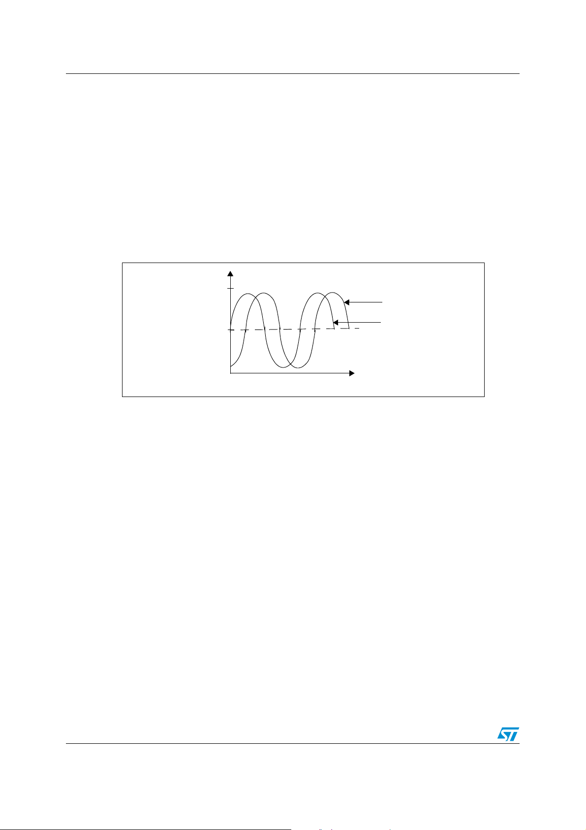
can be implemented without use of an external dedicated device (ASSP). Only a single 10bit SAR ADC is used to perform voltage and current measurements. The ADC on
ST7FLITE20 device accepts input from 0 to Vdd. Since the Vdd is +5V, the operable range
of the ADC is 0 to +5V. Since the ADC is operable in the positive range only, the AC input
signals of voltage and current have to shifted up and centered around +2.5V. This is
achieved by biasing one end of the secondaries of current transformers and one end of
potential divider with +2.5V. The input waveform of current and voltage to ADC is shown in
figure1.
Figure 1. AC input signals to ADC
V
Vdd
Voltage Waveform
Vdd/2
t
Current Waveform
Four ADC input channels are used, three for current and one for voltage measurement. One
of the current channels is multiplexed with two current gain factors x128 and x512. The
sampling rate for each channel is 5kHz. This higher rate of sampling is there to reduce the
quantization noise. The active energy consumed is calculated based on instantaneous value
of power. The sampling rate is 5kHz, so, with a 50Hz sinewave the number of samples per
cycle is 100. The sampling time is 200µs. After every 200µs, one current and voltage sample
is taken and multiplied to get an instantaneous power sample. The discrete summation of
these power samples over time gives the active energy.
When the phase difference between voltage and current is 0, the active power will be at the
maximum which is equal to total power, and the reactive power will be 0.
If v(t) = Vsin(ωt) and i(t) = Isin(ωt - φ), the instantaneous power:
VI 2⁄() φ()cos 2ωt φ–()cos–()=
Pt() vt() it()×=
After averaging, we get cos(2ωt - φ)=0 for a cycle of sinewave. So, the theoretical average
power (P) is VIcos(φ)/2. If ik and vk are respectively the instantaneous values of the current
and the voltage, the discrete formula of average power with regular, simultaneous, voltage
and current samples is:
N-1
1N⁄()vk ik×
=
P
d
∑
K=0
6/29
Page 7

AN2288 Theory
So, the average active energy over a time period with N samples is:
sampling
N-1
∑
K=0
vk ik×
Edt
=
There is delay (δ) between each voltage and current sample, due to this the real phase shift
angle (α) between v(t) and i(t) is different than theoretical phase shift angle (φ). So, there is
a discrete error (ε
):
d
P
P ε
+=
d
ε
d
=
VI×
-------------
2N×
d
N-1
K=0
∑
2α 2Kωt φ–+()cos
The average ε
will be 0. So, Ed = E.
d
There is also error due to non-simultaneous sampling, which is shift error (ε
The total active energy including not simultaneous sampling will be:
3.1 Analog front end
The ADC used in this application is only one 10-bit SAR ADC for current as well as voltage
sampling. The voltage is reduced by potential divider and lifted up by Vdd/2 (e.g. 2.5V) and
then given to one of the ADC channels of ST7Lite20 microcontroller to get the digital
converted value after every 200us. The Lite2 timer RTC2 interrupt is used to get 200us.
The current value is measured using a current transformer with a 1:5000 turn ratio and with
36 Ohm shunt resistance. The voltage induced across the current transformer is lifted up by
3V
/4 (e.g. 3.75V) to make the induced voltage unipolar (because the microcontroller
DD
works in one direction only). Two analog switches are used for tampering detection
phenomena. The output of both switches are connected, but the inputs are different, one
from phase line and the other one from neutral line. The output goes to gain multipliers e.g.
operational amplifiers. There are four gain multipliers implemented by three operation
amplifiers and with one analog switch. The gain factors are x2, x8, x32 and x128. The x32
and x128 are multiplexed using one op-amp and one analog switch. The output of the gain
multipliers goes to the ADC channels of the microcontroller. The active channel for current is
selected based on current range.
ε
P
P
E
ns
ns
ns
ns
VI×
-----------
δφ()sin
2
P εnsε
++=
P ε
+=
ns
E
ε
+=
d
∑
):
ns
N1–
δ
--- -
+=
∑
N
K0=
d
d
2α 2Kωt φ–+()cos
7/29
Page 8
Theory AN2288
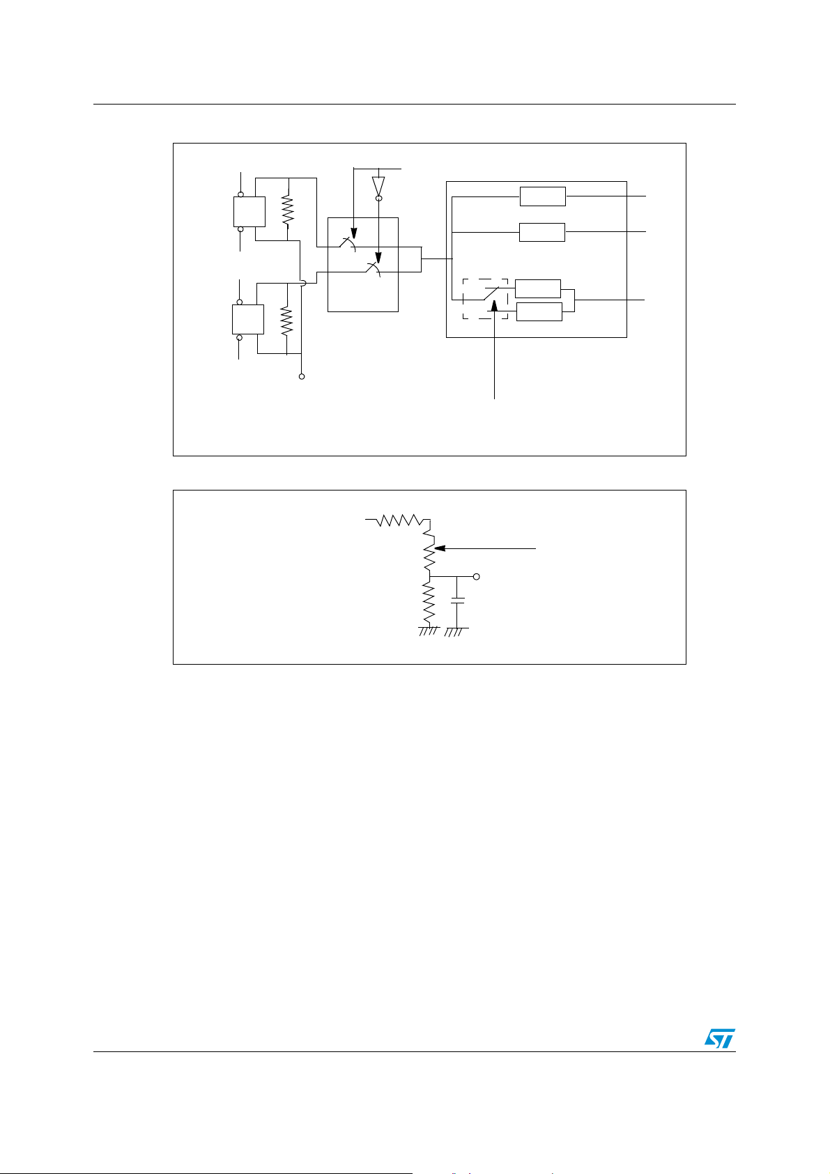
Figure 2. Analog Front End (AFE) for current
Phase In
Phase Out
Neutral In
Neutral Out
Current Transformer
36 Ohm
36 Ohm
analog switches
+3.75V
Control by MCU
Figure 3. Analog Front End for voltage
Phase
x2
x8
x32
x128
analog switch
Gain multipliers
Controlled by MCU
To MCU ADC
To MCU ADC
+3.75V
8/29
Page 9
AN2288 Meter hardware
4 Meter hardware
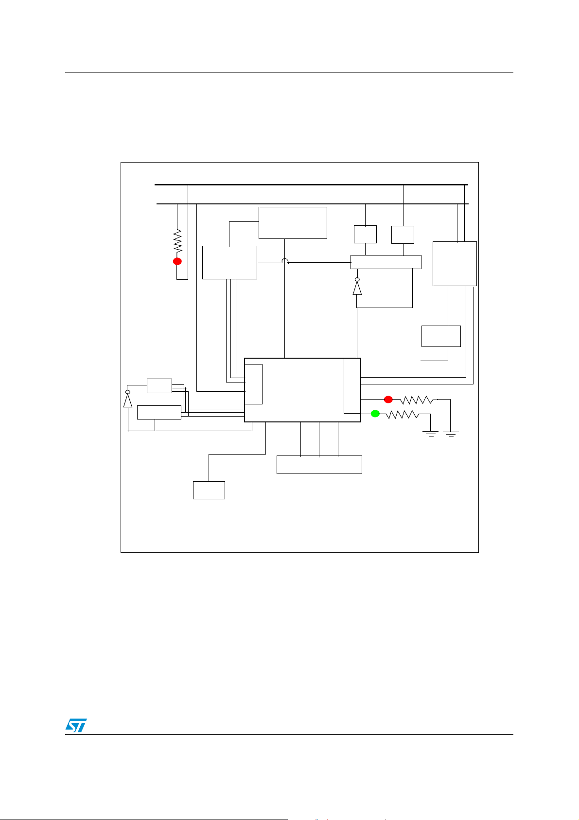
The block diagram of meter hardware is shown below:
Figure 4. Energy meter block diagram
Neutral line
Phase line
Power LED
RTC
EEPROM
EEPROM/RTC
Op-Amps for
gain x2, x8,
x32 & x128
Phase voltage
SPI
ICP
Analog switch for
gain factor b/w
x32 & X128
Control for
switching
between x32
& x\128
ST7FLITE20
ADC
control for switching
between CTs
LCD module
CT
Analog switches
Power supply
CT
Used for
reference
Tamper LED
Energy pulse
output LED
AC to DC
capacitive
power supply (5V)
3.75V
Voltage
follower
CT = Current Transformer
ICP = In-Circuit Programming
9/29
Page 10

Meter hardware AN2288
4.1 Main blocks
These are the main blocks in the Meter:
● 5V Power supply block
● 3.75V reference block
● Current Transformer block
● Voltage divider block
● Tamper detection block
● Gain switching block
● EEPROM block
● RTC block
● LCD Module
● In-Circuit Programming block
● Calibration through PC GUI
● Microcontroller block
4.1.1 5V power supply block
The 5V capacitive power supply is based on full-wave rectification. The positive half wave is
used to charge the capacitor and as well as negative half wave of sinewave is also used to
charge the capacitor in the same direction. The zener diode (ZD1) tells to which voltage the
C3 is charged. Voltage regulator U1 utilizes the energy stored in C3 to produce a stable
output voltage. Resistor R1 controls the charge and discharge of C1 and also limits the
current flow through zener diode ZD1. Two inductors (L1 and L2) are used to reduce the
noise in power supply.
Figure 5. Capacitive power supply
Phase line
L1
C4
Neutral line
L2
R1
R2
4.1.2 2.5V reference block
A potential divider is used to get a 3.75V reference. As some current (I2) flows towards the
voltage follower (refer to Figure 6), the current through R5 is higher than that through R6. If
R5=R6, there is a voltage drop of R5*I2 in the reference. This voltage drop is variable, which
depends on the current flow through reference I2. If I2 is negligible and constant, this
3.75Vref will be ~3.75 and constant. So, a voltage follower is used to get ~3.75V constant
reference.
C1
C2
D4
D1
D2
D3
R3
ZD1
C5
C3
5V
L7805
C6
10/29
Page 11

AN2288 Meter hardware
Figure 6. 2.5V reference circuit
5V
R5
R6
I1+I2
I2
3.75V - R5*I2
I1
4.1.3 Current transformer block
The current transformer used has a turn ratio of 1:5000 and ~350 Ohm resistance, the shunt
resistance used is 36 Ohms (refer fig. 2), so, the effective resistance will be:
R
shunt
After multiplication of secondary current with R
be:
V
V
is multiplied with gain stage to give actual value to input to microcontroller ADC. The
shunt
minimum multiplication factor is x2. The MAX current is chosen such that the operational
amplifier should not saturate. So, with x2 the max value of V
350 36×
---------------------- - 32.64E==
350 36+
55A
shunt
------------ -
5000
-
3.75Vref
× 359mV==
R
shunt
+
, the voltage V
shunt
AIN
is:
3.75V
for max current will
shunt
V
AIN
The peak to peak voltage is 2.03V. There is safe margin of ~0.47V for a gain factor of x2.
4.1.4 Voltage divider block
The voltage is reduced using a potentiometer and referenced at 3.75V.
Figure 7. Voltage divider circuit
Phase
Neutral line
R28
R29
R31
MAX()359m V 2× 2× 1.015V==
R30
C12
R26
Analog input to ADC
C20
2.5V
11/29
Page 12

Meter hardware AN2288
4.1.5 Tamper detection block
Two analog switches and one control pin with one fast switching transistor is used to detect
tampering.
Figure 8. Tamper detection circuit
5V
Control signal from MCU
Voltage out from phase CT
To gain multiplier
Voltage out from Neutral CT
analog switches
4.1.6 Gain switching block
Gain multipliers are used to get the large load range with Ib=10A and Imax=55A. In this
application, there are four gain multipliers x2, x8, x32 and x128. A particular gain factor is
actively used by the microcontroller, depending on the signal strength. For the lowest signal
strength x128 gain factor is used. The operational amplifiers are used in non-inverting
mode.
Gain 1
⎛⎞
=
⎝⎠
R
F
------ -+
R
1
where RF is negative feedback resistance
is resistance at inverting terminal of Op-amp
R
1
The exact gain factors are:
x2 1
x8 1
x32 1
x128 1
------------- -+
⎝⎠
470E
1.5K
⎛⎞
------------- -+
⎝⎠
220E
16K 51K
⎛⎞
-------------------------- -+
⎝⎠
51K
⎛⎞
------------- -+
⎝⎠
390E
||
390E
2==
7.818==
32.23==
131.77==
470E
⎛⎞
When the voltage after x2 multiplier decreases below ~2.03Vp-p/4(=~0.508V), the gain
factor will change to x8 or when the voltage after x8 multiplier increases after ~2.03V, the
gain factor will change to x2. There is some hysteresis also implemented for this. So, when
upper half of sinewave after x2 decreases below ~0.508V/2 (= ~0.254V), the active gain
12/29
Page 13

AN2288 Meter hardware
factor will change to x8 or when upper half of sinewave after x8 increases after 1.015V, the
active gain factor will change to x2. The Irms will be:
2Irms× R
----------------------------------------------------------------- - 0.253V=
5000
shunt
x2×()×
The same logic applies with the x8 voltage multiplier. Below ~0.508V, the gain factor
increases to x32. At this level, when the voltage increases higher than 2.03V, the gain factor
drops back to x8. The Irms can be calculated (using just the upper half of the sinewave):
Irms
13.7 7.818×
-------------------------------- - 3.32A==
32.23
The same logic applies with the x32 voltage multiplier. Below ~0.508V, the gain factor
increases to x128. At this level, when the voltage increases higher than 2.03V, the gain
factor drops back to x32. The Irms can be calculated (using just the upper half of the
sinewave):
Irms
3.32 32.23×
-------------------------------- - 0.81A==
131.77
13/29
Page 14

Meter hardware AN2288
Figure 9. Gain switching circuit
3.75V
R8
R9
From Analog switch
3.75V
R7
R14
3.75V
From Analog switch
-
+
-
+
R13
Analog input to ADC
x 2
R10
Analog input to ADC
x 8
Microcontroller
Controlled by MCU
R12
R11
-
x32 or
x128
From Analog switch
+
4.1.7 EEPROM block
After power up, the accumulated kWh data, tampering information and calibration
parameters are read by the microcontroller and stored in the form of RAM variables. When
the meter is tampered, the tampering information (meter is tampered and tampered
channel) will be stored in the EEPROM immediately. When power goes off, the accumulated
kWh data will be stored in the EEPROM.
14/29
Analog input to ADC
C39
Page 15

AN2288 Meter hardware
Figure 10. EEPROM circuit
4.1.8 RTC block
RTC block is used to show current date and time. When power goes down, RTC will be
entered in low power mode and then power will be given by rechargeable battery of 3.6V, so
that internal RTC registers gets updated according to the real time. When power goes up,
supply is given by Vcc and battery charging is started.
Figure 11. RTC circuit
3.6V
M95010
V
BAT
M41T94
NS
Q
C
D
NS
SDO
SCL
Selection of Chip
Selection of Chip
PA0
MISO
SCK
MOSI
Microcontroller
SPI
PA0
MISO
SCK
GND
4.1.9 LCD module
GDM093 module is used to display accumulated kWh, instantaneous rms voltage,
instantaneous rms current, instantaneous power factor and line frequency. This LCD module
uses HT1621 controller. This module has 18X4 segment.
SDI
MOSI
Microcontroller
SPI
15/29
Page 16

Meter hardware AN2288
Figure 12. LCD circuit
NCS
NWR
DATA
5V
PA3
PA2
PA1
Microcontroller
4.1.10 In-Circuit Programming block
By using In-Circuit Programming, the microcontroller can be programmed even when the
meter is installed and running. There are only five pins used from the 10-pin HE10 ICC
connector. One oscillator pin is also optional. In all, there are only four mandatory pins.
Figure 13. ICP connector
1
10-pin
HE120
5V
OSC
connector
9
10
2
ICCDATA
ICCCLK
RESET
16/29
Page 17

AN2288 Meter hardware
4.1.11 Calibration through PC GUI
Calibration of the meter and initialization of the RTC can be done using the PC GUI. To enter
calibration mode the user has to press switch S1 within 30 seconds of power-on of the
meter.
Figure 14. Calibration mode
PA2
S1
4.1.12 Microcontroller block
The microcontroller is the heart of the energy meter, it does all the calculations and
measurements. Only a 20-pin package is used. Refer to Figure 4 for more details.
17/29
Page 18

Software routines AN2288
5 Software routines
This section of the application note describe each function contained in the firmware. A
general description and flow diagram are provided for each routine.
5.1 Initialization routine
The two routines are used for initialization. The ASM_init routine is used to initialize the
global variables, which is done using the _stext routine, the auto startup routine. After this
routine the init routine is called which initializes different bool variables, portA register, ADC
bits and SPI.
Figure 15. Initialization routine
Init routine
Initialize 18-bool variables;
Initialize portA;
Call a delay routine to wait for 5V supply to reach to 5V;
Initialize ADC: Amp not selected, calibration OFF, slow bit = 0
Initialize SPI: software slave is used, SPI freq = Fcpu/4, SPI inter-
rupt enabled, read from memory array
5.2 Main routine
The main routine is called after ASM_init (_stext), which called different functions.
ASM_init
Initialize global variables
18/29
Page 19

AN2288 Software routines
Figure 16. Main routine
ASM_init ( )
main
init ( )
PA2 port configured for
calibration mode detection
Enable interrupts
Initialize LCD module
Referesh LCD to make
all segments null
Display kWh, Vrms, Irms, power
factor, line frequency, Current
Date and Time in rolling manner
Anti tampering detection algorithm
to detect whether phase or neutral
line tampering is done or not
Update kWh energy variable to update kWh based on pulses
Gain switching is done based on
current magnitude
19/29
Page 20

Software routines AN2288
5.3 Lite timer time base2 interrupt routine
This routine is the heart of the MCU, which is generated after every 200µs. This means with
a 50Hz sinewave the number of samples per cycle is 100. In this interrupt routine, the
voltage and current samples are taken by changing the active channel for ADC. One current
sample is taken in between the two voltage sample. The two voltage samples are taken to
minimize the error due to a shift in sampling time for voltage and current sample.
Multiplication and accumulation of V*I is done separately for each current gain.
Figure 17. Lite timer interrupt routine
LT_TB2_IT_Routine
no
Is AVDF flag=0 &
AVD_INTERRUPT =
Disabled?
yes
Enable AVD interrupt
Clear TimeBase2
interrupt Flag
EnableInterrupts
Read first Voltage Sample
Read Curent Sample
Read Second Voltage Sample
Average V1 and V2
A
20/29
Page 21

AN2288 Software routines
Figure 18. Lite timer interrupt routine (Cont’d)
A
Find out current peak,
voltage peak, frequency
and power factor
tampering detection by checking at
both phase and neutral current chan-
nel for 6 times after every 500ms
INS_POWER = V * I
TOTAL_POWER [GAIN] +/-=
INS_POWER
Pulse output according to
3200imp/kWh
no
count = 1
Gain_switching++
Data sent to PC GUI as request-
ed for different gain factor
Is count < 100 ?
end
yes
count++
21/29
Page 22

Software routines AN2288
5.4 SPI interrupt routine
This routine is called just after power up of the application. This routine is used to initialize
the EEPROM if the meter is used for the first time or to get the previous accumulated kWh
and tampering information. The one pulse comparison factors and display constants are
also received from EEPROM.
Figure 19. SPI interrupt routine
SPI_IT_Routine_INIT
Disable SPI interrupt
Clears SPI interrupt flag
Read first byte from EEPROM
from address 0x00
temp = Read byte from EEPROM
Read stored calibration fac-
tors and display factors
no
temp!=init_EEPROM
Write new values of different calibra-
tion factors and display factors
Set the Lite timer timebase2 for 200us
interrupt and enable interrupt, ADC on
Is
[0]?
yes
end
22/29
Page 23

AN2288 Software routines
5.5 AVD interrupt routine
This routine is used to store accumulated kWh and tampering information to EEPROM
during power down.
Figure 20. AVD Interrupt power down routine
AVD_Interrupt_Power_Down
Disable AVD interrupt
Write 4-bytes of kWh and
one byte of tampering infor-
mation to EEPROM
end
5.6 External interrupt routine
If the user wants to enter PC calibration mode, he should press the switch within ~30Sec of
start of the application. Application will enter into external interrupt routine by pressing the
external switch. Now external interrupt routine will wait for interrupt coming from PC GUI.
Figure 21. External interrupt routine
External Interrupt
Disable AVD interrupt
Wait for input capture inter-
rupt which is coming from
PC GUI
end
5.7 ART timer input capture interrupt routine
In this application, SCI is simulated using the 12-bit ART TImer. Different commands are
received by software SCI, and a response is sent back to the PC GUI using the ART timer
overflow interrupt.
23/29
Page 24

Results AN2288
6 Results
This section shows the results obtained for the reference design. These results were
obtained at a test house using recognized MTE test equipment. There are three types of
tests performed:
1. Load tests: Voltage and frequency of AC Source is constant, but the load current
varies. These tests are performed for resistive load (unity power factor), 0.5Lag and
0.8Lead.
2. Voltage tests: Frequency of AC source and load current (basic current) is constant, but
the voltage is changed from minimum (140V) to maximum (280V). This test is
performed at UPF, 0.5Lag, 0.8Lag and at 0.8Lead.
3. Frequency tests: Voltage and load current (basic current) is constant, but the
frequency of AC Source is changed from 48Hz to 52Hz. This test is performed at UPF,
0.5Lag, 0.8Lag and at 0.8Lead.
6.1 Load tests
The voltage is 234.5V and the frequency of AC source is 50Hz. Below is the table for the
accuracy Vs. load current.
Table 1. Load current Vs% error
Load current Vs% Error
Load Current [A] UPF (%Error) 0.5 LAG (%Error) 0.8 LEAD (%Error)
53 (5.3Ib) -0.71 -0.58 -0.68
50 (5Ib) -0.34 0.08 -0.55
14 (1.4Ib) -0.22 0.06 -0.54
13 (1.3Ib) -0.14 0.09 -0.42
4 (0.4Ib) -0.11 0.11 -0.41
3 (0.3Ib) -0.04 0.23 -0.28
1 (0.1Ib) -0.24 0.54 -0.35
0.8 (0.08Ib) -0.09 0.62 -0.19
0.5 (0.05Ib) -0.11 -0.74 0.4
0.2 (0.02Ib) 0.19 -0.39 0.79
The % error is within the +-1% error for the range 0.05 Ib < I < 5.5Ib, as required for a class1
meter. Here Imax is 5.5In. The startup current is ~11mA, which is ~0.02% of Imax.
24/29
Page 25

AN2288 Results
6.2 Voltage tests
This test is performed at UPF, 0.5Lag, 0.8Lag and at 0.8Lead. Below is the table for the
accuracy Vs. voltage variation.
Table 2. Voltage vs% error
Voltage Vs% Error
Voltage [V] UPF (%Error) 0.5LAG (%Error) 0.8LAG (%Error)
140 -0.68 -0.35 -0.15 -0.99
280 -0.68 0.0 -0.6 -0.68
6.3 Frequency tests
This test is performed at UPF, 0.5Lag, 0.8Lag and at 0.8Lead.
Table 3. Frequency Vs% Error
Frequency [Hz] UPF (%Error) 0.5LAG (%Error) 0.8LAG (%Error)
48 0.2 0.5 0.48 -0.39
52 0.15 0.2 0.09 -0.23
0.8LEAD
(%Error)
Frequency Vs% Error
0.8LEAD
(%Error)
25/29
Page 26

Conclusions AN2288
7 Conclusions
This electricity meter solution demonstrates that a modular low cost, single chip, digital
energy meter can be implemented with the ST7FLITE20 microcontroller, which is 20-pin
device and has a minimum set of mainly discrete external components. The on-chip 10-bit
ADC with external gain circuits is used instead of a dedicated external measurement IC, to
perform all the voltage, current and energy measurements. The error in measured energy is
within the IEC61036 standard.
The ST7FLITE20 MCU provides a very cost effective solution for a power meter, as it
enables the removal of the dedicated energy measurement device and has a large set of on
chip peripherals like LVD/AVD, Lite Timer, SPI, 10-bit ADC. The other ICs used are L7805
(positive voltage regulator), BC547 (NPN silicon transistor), PN2222A (NPN high speed
switching transistor), TS1854 (Quad rail-to-rail low power operational amplifiers), M95010
(1Kbit serial SPI bus EEPROM) and M41T94 (RTC).
The internal EEPROM of ST7FLITE20 microcontroller can also be used by changing the
sales type of the microcontroller and with some minute firmware changes.
The modular design approach enables the hardware and software to be reused and thus
speed up the design cycle for a power meter development. The schematics, Bill of Materials,
gerber files and software are all available at the ST website.
26/29
Page 27

AN2288 Calibration coefficients
8 Calibration coefficients
There are nine calibration coefficients in all. There are four current offset calibration
parameters, one voltage offset calibration parameter, four one pulse comparison constants
for all the four current gain factors.
27/29
Page 28

Revision history AN2288
9 Revision history
Table 4. Document revision history
Date Revision Changes
23-May-2006 1 Initial release.
28/29
Page 29

AN2288
r
Please Read Carefully:
Information in this document is provided solely in connection with ST products. STMicroelectronics NV and its subsidiaries (“ST”) reserve the right to make changes, corrections,
modifications or improvements, to this document, and the products and services described herein at any time, without notice.
All ST products are sold pursuant to ST’s terms and conditions of sale.
Purchasers are solely responsible for the choice, selection and use of the ST products and services described herein, and ST assumes no liability whatsoever relating to the
choice, selection or use of the ST products and services described herein.
No license, express or implied, by estoppel or otherwise, to any intellectual property rights is granted under this document. If any part of this document refers to any third party
products or services it shall not be deemed a license grant by ST for the use of such third party products or services, or any intellectual property contained therein or consi dered
as a warranty covering the use in any manner whatsoever of such third party products or services or any intellectual property contained therein.
UNLESS OTHERWISE SET FORTH IN ST’S TERMS AND CONDITIONS OF SALE ST DISCLAIMS ANY EXPRESS OR IMPLIED WARRANTY WITH RESPECT TO THE
USE AND/OR SALE OF ST PRODUCTS INCLUDING WITHOUT LIMITATION IMPLIED WARRANTIES OF MERCHANTABILITY, FITNESS FOR A PARTICULAR
PURPOSE (AND THEIR EQUIVALENTS UNDER THE LAWS OF ANY JURISDICTION), OR INFRINGEMENT OF ANY PATENT, COPYRIGHT OR OTHER INTELLECTUAL
PROPERTY RIGHT.
UNLESS EXPRESSLY APPROVED IN WRITING BY AN AUTHORIZE REPRESENTATIVE OF ST, ST PRODUCTS ARE NOT DESIGNED, AUTHORIZED OR WARRANTED
FOR USE IN MILITARY, AIR CRAFT, SPACE, LIFE SAVING, OR LIFE SUSTAINING APPLICATIONS, NOR IN PRODUCTS OR SYSTEMS, WHERE FAILURE OR
MALFUNCTION MAY RESULT IN PERSONAL INJURY, DEATH, OR SEVERE PROPERTY OR ENVIRONMENTAL DAMAGE.
Resale of ST products with provisions different from the statements and/or technical features set forth in this document shall immediately void any warranty granted by ST fo
the ST product or service described herein and shall not create or extend in any manner whatsoever, any liability of ST.
ST and the ST logo are trademarks or registered trademarks of ST in various countries.
Information in this document supersedes and replaces all information previously supplied.
The ST logo is a registered trademark of STMicroelectronics. All other names are the property of their respective owners.
© 2006 STMicroelectronics - All rights reserved
Australia - Belgium - Brazil - Canada - China - Czech Republic - Finland - France - Germany - Hong Kong - India - Israel - Italy - Japan - Malaysia - Malta - Morocco - Singapore
- Spain - Sweden - Switzerland - United Kingdom - United States of America
STMicroelectronics group of companies
www.st.com
29/29
 Loading...