

Page 1

AN2281
Application note
Low cost self-synchronizing PMAC
motor drive using ST7FLITE35
Introduction
Due to their high efficiency, power by size ratio and silent operation, Permanent Magnet AC
(PMAC) motors are increasingly used in many applications. They are becoming the
predominant type of motor used in applications where the above advantages are required,
especially fans, compressors and pumps.
Since PMAC motors are synchronous machines, to get the best efficiency from them, the
excitation must be switched from one motor phase to another in exact synchronism with the
rotor motion. This concept, commonly known as self-synchronization, uses direct feedback
of the rotor angular position to ensure that the PMAC machine never loses synchronization.
This application note describes a low-voltage single-sensor three-phase AC permanent
magnet motor, also known as PMAC or BLAC (brushless AC) control system.
It includes a depiction of:
● Reference schematics, which can be used for up to 12V-50W PMAC motors and based
on ST7LITE35 microcontroller and on STS8C5H30L complementary P-channel and Nchannel MOSFETs,
● Firmware library, developed with the Cosmic C compiler and STVD7 release 3.x.x. It is
composed of several C modules containing a set of convenient functions for sinusoidal
waveform generation, synchronization mechanism and closed loop control of PMAC
motors.
March 2006 Rev 1 1/38
www.st.com
Page 2

Contents AN2281
Contents
1 Theory of Operation . . . . . . . . . . . . . . . . . . . . . . . . . . . . . . . . . . . . . . . . . 3
2 PMAC motor control basics . . . . . . . . . . . . . . . . . . . . . . . . . . . . . . . . . . . 5
3 Implementation on the ST7Lite35 microcontroller . . . . . . . . . . . . . . . . . 6
3.1 ST7Lite3x 12-bit Autoreload timer (ART) in PWM mode . . . . . . . . . . . . . . 6
3.2 Lite Timer for measuring the rotor speed . . . . . . . . . . . . . . . . . . . . . . . . . . 9
3.3 Lite Timer configuration for measuring the Hall sensor period . . . . . . . . . 10
4 Application schematics . . . . . . . . . . . . . . . . . . . . . . . . . . . . . . . . . . . . . 13
4.1 Gate driving and dead time insertion circuit . . . . . . . . . . . . . . . . . . . . . . . 14
5 Library parameters . . . . . . . . . . . . . . . . . . . . . . . . . . . . . . . . . . . . . . . . . 16
5.1 Phase synchronization and Phase angle optimization . . . . . . . . . . . . . . . 16
5.2 Start-up phase parameters . . . . . . . . . . . . . . . . . . . . . . . . . . . . . . . . . . . 17
6 Getting started with the ST7FLITE35-based PMAC motor control
system . . . . . . . . . . . . . . . . . . . . . . . . . . . . . . . . . . . . . . . . . . . . . . . . . . . 20
6.1 Hardware connections . . . . . . . . . . . . . . . . . . . . . . . . . . . . . . . . . . . . . . . 20
6.2 Development Tools . . . . . . . . . . . . . . . . . . . . . . . . . . . . . . . . . . . . . . . . . . 20
6.3 Library source code . . . . . . . . . . . . . . . . . . . . . . . . . . . . . . . . . . . . . . . . . 22
6.4 How to set the library parameters to run a PMAC motor for the first time 23
7 Conclusion and results . . . . . . . . . . . . . . . . . . . . . . . . . . . . . . . . . . . . . . 25
7.1 Motor control related CPU load . . . . . . . . . . . . . . . . . . . . . . . . . . . . . . . . 25
7.2 Code memory size . . . . . . . . . . . . . . . . . . . . . . . . . . . . . . . . . . . . . . . . . . 26
7.3 Example oscilloscope captures . . . . . . . . . . . . . . . . . . . . . . . . . . . . . . . . 26
Appendix A List of software functions and Interrupt Service Routines . . . . . . 31
2/38
Page 3
AN2281 Theory of operation
1 Theory of operation
Standard induction motors, normally designed to run at base speeds between 850 to 3500
rpm, are not particularly well suited to low-speed operation, as their efficiency drops with the
reduction in speed. They may also be unable to deliver sufficient smooth torque at low
speeds.
The use of a gearbox is the traditional mechanical solution to this problem. However, the
gearbox is a complicated piece of machinery that takes up space, reduces efficiency, and
needs both maintenance and significant quantities of oil. Replacing the gearbox with
permanent magnet motors/drive configurations saves space and installation costs, energy
and maintenance, and provides more flexibility in production and facility design. These
motors use magnets to produce the magnetic rotor field rather than the magnetizing
component of the stator current like in the induction motor.
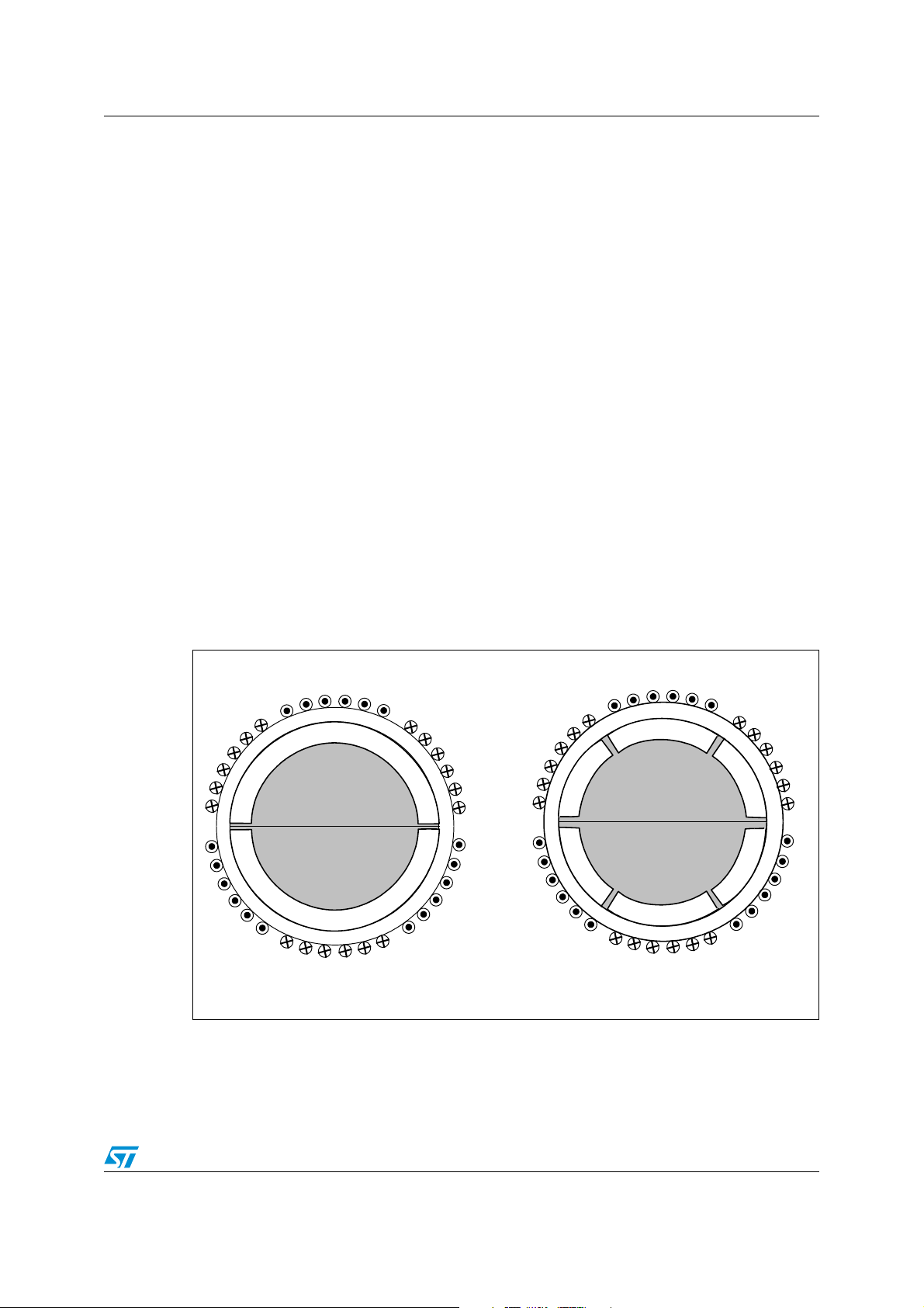
Figure 1 shows a cross section of a typical permanent magnet (PM) motor. The rotor has an
iron core on the surface of which is mounted a thin permanent magnet. An alternating
magnet of opposing magnetization produces radial directed flux density across the air gap.
This flux then reacts with currents in the stator windings to produce torque.
The two most common types of brushless PM motors are classified as:
● Synchronous, with a uniformly rotating stator field as an induction motor. This type is
also referred to as PMAC (BLAC)
● Switched or trapezoidal, with stator fields that are switched in discrete steps. This type
is also referred to as PMDC (BLDC)
Figure 1. Cross-section of PM motors
a
-b
N
c
S
-a
1 pole pair
-c
b
-b
c
a
N
-c
S
N
S
-a
3 pole pairs
S
N
b
3/38
Page 4
Theory of operation AN2281
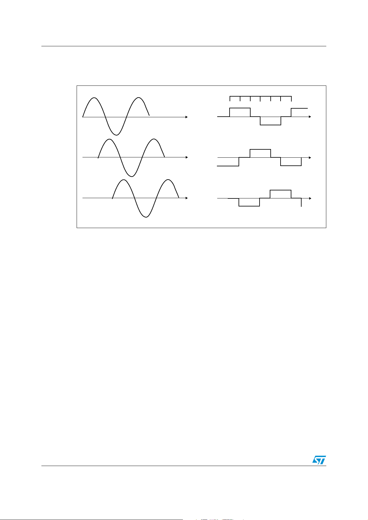
Figure 2 provides a direct comparison of ideal current excitation waveforms for typical three-
phase sinusoidal and trapezoidal PM motors.
Figure 2. Sinusoidal (PMAC) and trapezoidal (PMDC or 6-step) current excitation
123456
Phase A
120°
240°
(a) Sinusoidal
Phase B
Phase C
120°
240°
(b) Trapezoidal
PMDC motors are specifically designed to develop nearly constant output torque when
excited with a six-step switched current waveform. Their stator windings are concentrated
into narrow phase belts. The resulting back-EMF voltage, induced in each stator phase
winding during rotation, can be modeled quite accurately as a trapezoidal waveform.
PMAC motors are, on the contrary, specifically designed to be excited with a sinusoidal
current waveform. Their stator windings are typically distributed over multiple slots in order
to approximate a sinusoidal distribution so that the resulting back-EMF waveforms
generated are sinusoidal shaped.
Except for the intrinsic characteristics of stator windings, a PM machine can be excited with
both drive methods without any great loss of efficiency. The main difference between the two
types of excitation consists of the acoustic noise generated. The abrupt variation of the
trapezoidal phase current, in fact, generally introduces a great amount of acoustic and
electronic noise in comparison to the sinusoidal phase current.
In the 6-step PMDC method, one of the three phases is always unexcited, making it possible
to access back-EMF zero-crossing (i.e. rotor position) information, while in a PMAC motor
drive the three phases are always excited during the electrical period, making it necessary
to use at least one rotor position sensor.
Nevertheless, the relatively reduced amount of noise when a PM motor is excited with
sinusoidal current in comparison to 6-step excitation makes it the preferred choice for all
applications in which audible noise is a critical issue.
Actually, some complex algorithms for driving PMAC sensorless motors have been
developed, but they require more computational power than would be available from an 8-bit
microcontroller.
4/38
Page 5
AN2281 PMAC motor control basics
2 PMAC motor control basics
PMAC machines are synchronous so the average torque can be produced only when the
excitation is synchronized with the rotor frequency and instantaneous position. By
continuously detecting the rotor angular position and rotational speed, the excitation can be
properly switched among the PMAC motor phases in exact synchronism with the rotor
motion.
This concept, commonly known as self-synchronization, uses direct feedback of the rotor
angular position to ensure that the PMAC machine never loses synchronization. Generally,
Hall sensors are used to get information about the angular position of rotor, detecting the
magnetic field direction generated by the rotor. In particular, the usage of only one sensor is
supported with the system presented in this document.
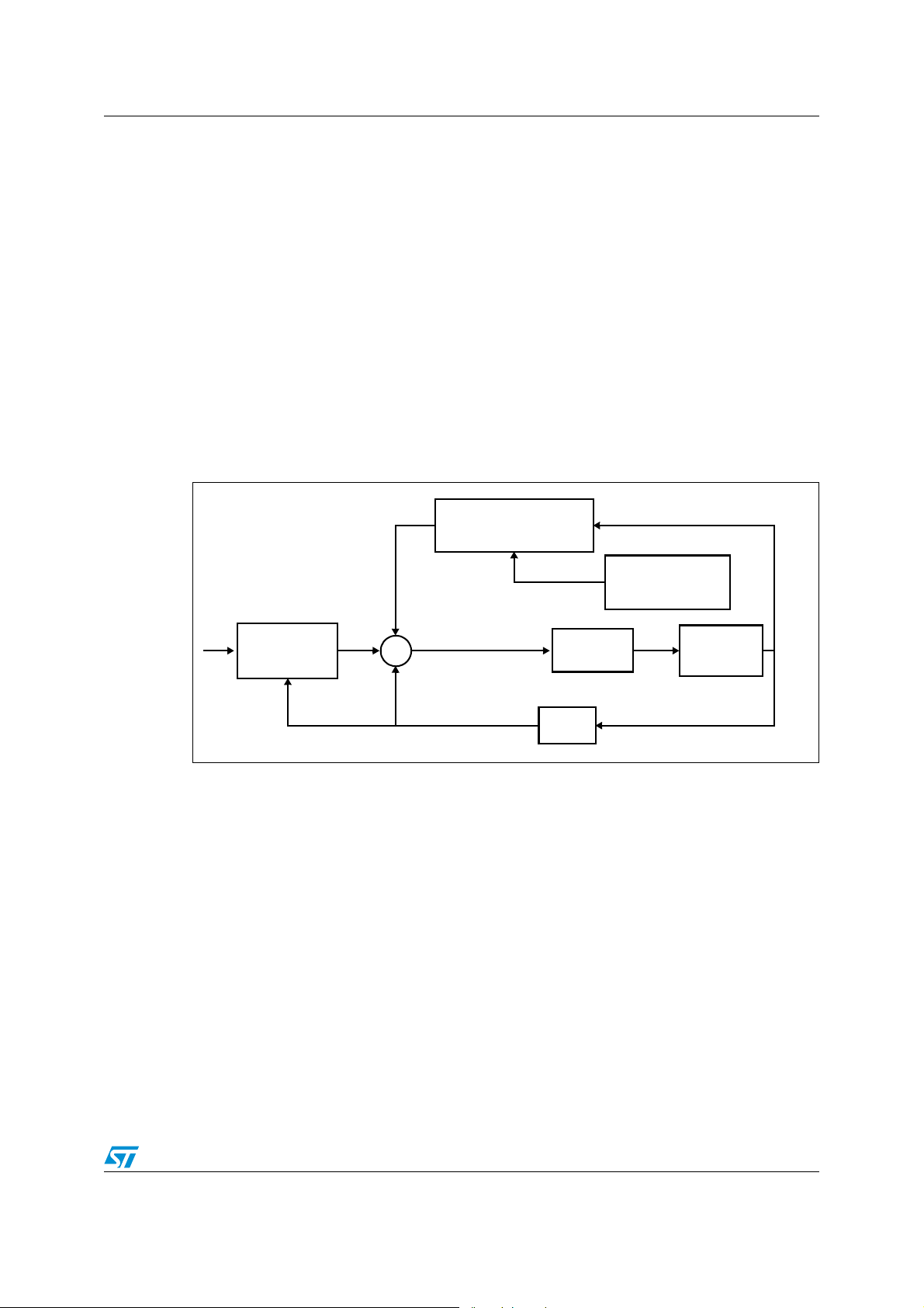
Figure 3 shows the block diagram of the PMAC self-synchronization algorithm implemented
in the software library.
Figure 3. PMAC motor control basics: the block diagram
Phase
synchronization
Φ
A
Each of the three phases of the motor is supplied by a sinusoidal waveform whose
frequency, amplitude and phase have been respectively indicated with f, A* and Φ.
Every time an Hall sensor signal transition occurs, the algorithm estimates the rotor
frequency f* and utilizes this value as statorical frequency (f) for the successive electrical
semi-period. Meanwhile, the phase of the sine wave is also updated and set equal to phase
angle Φ or Φ+π depending on the Hall sensor edge transition (rising or falling). Generally, for
a large operating speed range, the proper value of Φ is strongly dependent on the motor
speed affecting the driving efficiency. The provided library allows you to set the optimum Φ
as a linear function of the speed (in rpm).
V/F
Limitation
A*
A* sin(2πf+Φ)
f
Motor
f=f*
Rotor Position
Phase angle
optimization
Hall
sensor
f*
Since there are no direct information on current and torque, a V/F limitation has also been
implemented in order to allow you to limit the maximum flowing current for a given speed.
5/38
Page 6
Implementation on the ST7LITE35 microcontroller AN2281
3 Implementation on the ST7LITE35 microcontroller
The algorithm presented in the previous paragraph has been implemented on the
ST7FLITE35 microcontroller. Although they belong a family of low-cost ST microcontrollers,
ST7FLITE3x devices nevertheless have all the necessary features to be able to drive a
PMAC motor using one Hall sensor.
● The Lite Timer has been used to measure the period (or better the semi-period) of the
Hall sensor signal and the 12-bit autoreload Timer with its 4 PWM outputs has been
used to generate the three voltage phases.
● The internal RC oscillator with 1% tolerance allows you to further reduce the cost and
the size of the overall system and avoid PCB layout optimization issues related to the
presence of external oscillators.
3.1 ST7LITE3x 12-bit autoreload timer (ART) in PWM mode
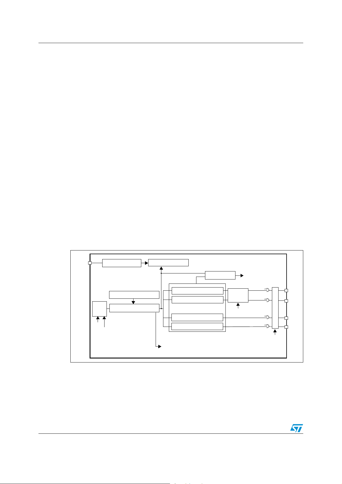
3.1.1 Block diagram and functional description
The 12-bit ART is based on one or two free-running 12-bit upcounters with an input capture
register and four PWM output channels.
The PWM mode of the dual 12-bit autoreload timer allows up to four Pulse Width Modulated
signals to be generated on the PWMx output pins. The four PWM signals can have the
same frequency (f
) or two different frequencies depending on the ENCNTR2 bit which
PWM
enables single timer or dual timer mode (see Figure 4 and Figure 5).
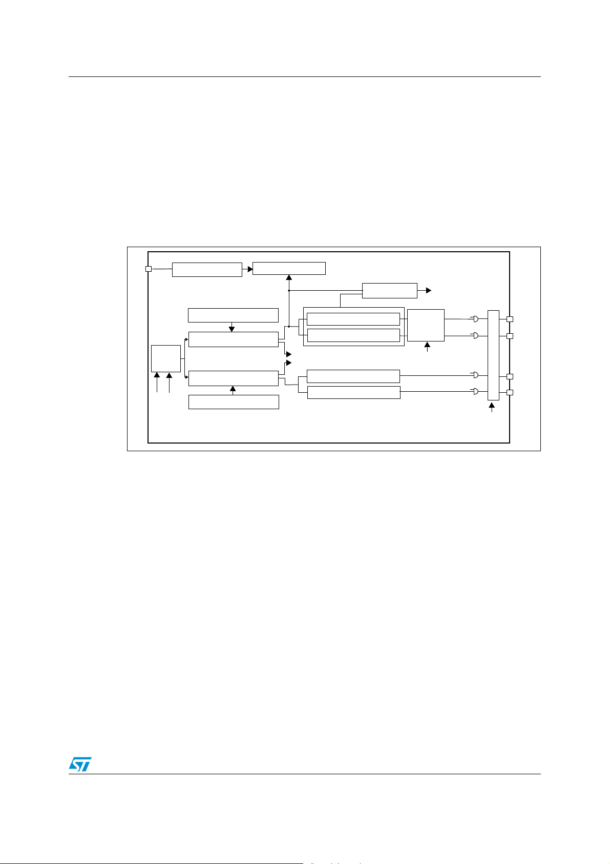
Figure 4. The dual 12-bit autoreload timer: single timer mode (ENCNTR2=0)
ATIC
Edge Detection Circuit
12-Bit Autoreload Register 1
Clock
Control
CPU
f
from Lite Timer
1ms
12-Bit Upcounter 1
12-bit Input Capture
PWM0 Duty Cycle Generator
PWM1 Duty Cycle Generator
PWM2 Duty Cycle Generator
PWM3 Duty Cycle Generator
OVF1 Interrupt
Output Compare
Dead Time
Generator
DTE bit
CMP
Interrupt
OE0
OE1
OE2
OE3
Break Function
BPEN bit
PWM0
PWM1
PWM2
PWM3
The PWM frequency is controlled by the counter period and the ATR register value following
formula
f
PWM
= f
COUNTER
/ (4096 - ATR) (3.1)
6/38
Page 7
AN2281 Implementation on the ST7LITE35 microcontroller
In dual timer mode, PWM2 and PWM3 can be generated with a different frequency
controlled by CNTR2 and ATR2.
The duty cycle is selected by programming the DCRx registers. These are preload registers.
The DCRx values are transferred in active duty cycle registers after an overflow event if the
corresponding transfer bit (TRANx bit) is set.
The TRAN1 bit controls the PWMx outputs driven by counter 1 and the TRAN2 bit controls
the PWMx outputs driven by counter 2.
PWM generation and output compare are done by comparing these active DCRx values
with the counter.
Figure 5. The dual 12-bit autoreload timer: dual timer mode (ENCNTR2=1)
ATIC
Edge Detection Circuit
12-Bit Autoreload Register 1
Clock
Control
12-Bit Autoreload Register 2
CPU
1ms
f
12-Bit Upcounter 1
12-Bit Upcounter 2
12-bit Input Capture
PWM0 Duty Cycle Generator
PWM1 Duty Cycle Generator
OVF1 interrupt
OVF2 interrupt
PWM2 Duty Cycle Generator
PWM3 Duty Cycle Generator
Output Compare
Dead Time
Generator
DTE bit
CMP
Interrupt
OE0
OE1
OE2
OE3
Break Function
BPEN bit
PWM0
PWM1
PWM2
PWM3
At reset, the counter starts counting from 0. When an upcounter overflow occurs (OVF
event), the preloaded Duty cycle values are transferred to the active Duty Cycle registers
and the PWMx signals are set to a high level. When the upcounter matches the active DCRx
value the PWMx signals are set to a low level. To obtain a signal on a PWMx pin, the
contents of the corresponding active DCRx register must be greater than the contents of the
ATR register.
The polarity bits can be used to invert any of the four output signals. The inversion is
synchronized with the counter overflow if the corresponding transfer bit in the ATCSR2
register is set.
The PWMx output signals can be enabled or disabled using the OEx bits in the PWMCR
register.
7/38
Page 8

Implementation on the ST7LITE35 microcontroller AN2281
3.1.2 Three-phase sinusoidal waveform generation
In order to produce the three-phase sinusoidal voltages, three of the four available PWM
outputs have been enabled. Since these three PWM signals must have the same frequency,
single timer mode has been selected (ENTNCR2=0).
To allow the necessary duty cycle updating, the OVFIE bit of the ATCSR register has been
set. This way an interrupt is generated every 1/f
Furthermore, to reduce the acoustical noise introduced by the switching of the three-phase
inverter, a PWM frequency out of the audible range has been chosen. In particular, to
achieve the selected 15.625 KHz switching frequency, f
f
(8 MHz) and, consequently, using formula (3.1), the ATR1 registers have been written
CPU
with value 3584.
To reduce the contribution of the OVF interrupt service routine to the overall CPU load, the
calculations necessary for computing the three sinusoidal varying duty cycles are carried
out once per two PWM periods (that is once every two interrupts). This way, the number of
traced points per sine wave period (NP) is given by:
f
2 * f
PWM
SINE
NP =
Since at least 18 samples per sine wave cycle must be traced to generate a sine wave with
a Total Harmonic Distortion minor than 5%, (3.2) limits the maximum sine wave frequency to
434 Hz that is equivalent to about 26,000 rpm for an one poles pair motor.
PWM
seconds.
COUNTER
has been fixed equal to
(3.2)
3.1.3 Third harmonic modulation
Basically, to provide the voltage needed for the PMAC motor, the reference PWM signal
could be a pure sine wave, but this kind of modulation has the drawback that it makes poor
usage of the DC bus voltage.
Adding a third harmonic modulation to the reference sine wave, allows the phase-to-phase
voltage amplitude to be increased without deteriorating current and phase-to-phase voltage
THD (a 120-degree phase-shift on the fundamental corresponds to a 360-degree shift for
the third harmonic). On this subject, the literature demonstrates that, if the third harmonic
amplitude is equal to one sixth of the fundamental one, it is possible to increase the phaseto-phase voltage amplitude by 15% with respect to the pure sine wave approach.
8/38
Page 9
AN2281 Implementation on the ST7LITE35 microcontroller
3.2 Lite timer for measuring the rotor speed
3.2.1 Block diagram and functional description
The Lite timer (LT) can be used for general-purpose timing functions. It is based on two freerunning 8-bit upcounters and one 8-bit input capture register.
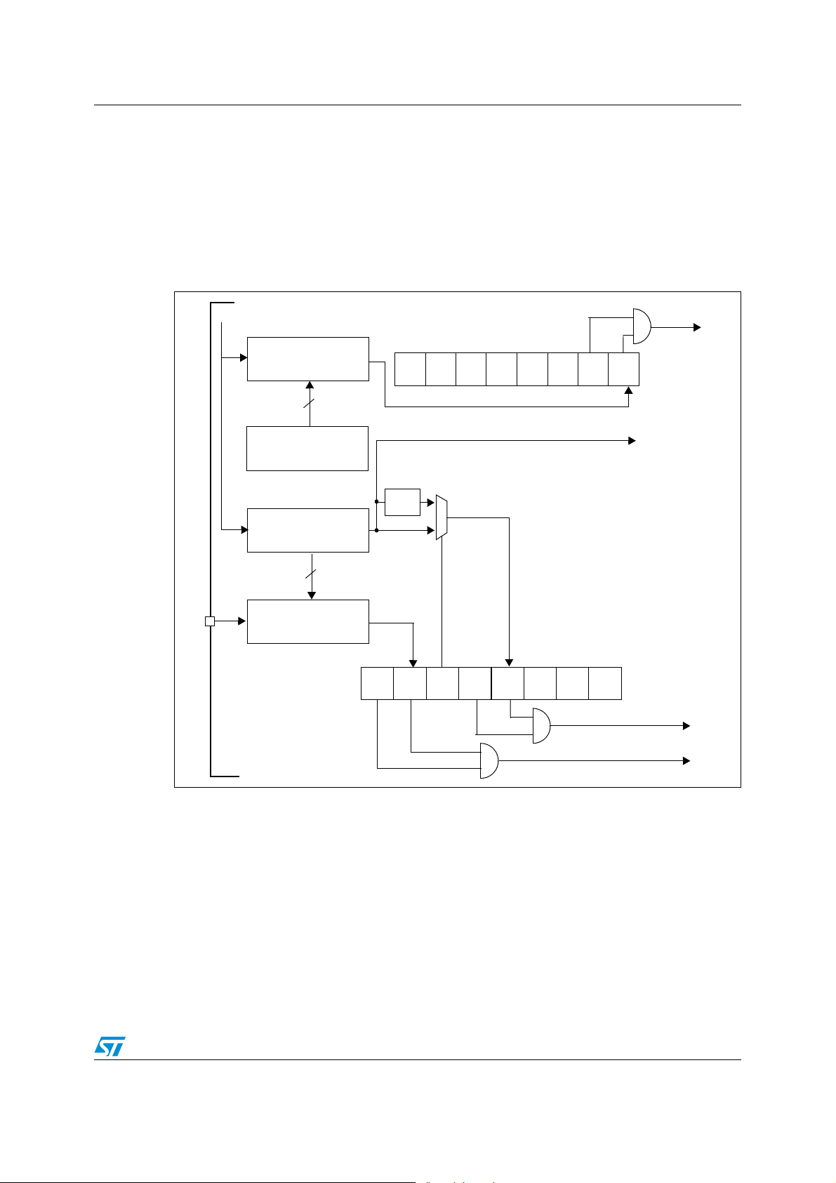
Figure 6 shows the Lite timer block diagram.
Figure 6. The Lite timer block diagram
/32
f
OSC
LTCNTR
8-bit TIMEBASE
COUNTER 2
LTCSR2
00
0
00
0
TB2IE
LTTB2
Interrupt request
TB2F
LTARR
8-bit AUTORELOAD
8-bit TIMEBASE
LTICR
LTIC
INPUT CAPTURE
After an MCU reset, counter 1 starts incrementing from 0 at a frequency of f
overflow event occurs when the counter rolls over from F9h to 00h. If f
8
REGISTER
COUNTER 1
8
8-bit
REGISTER
f
LTIMER
LTCSR1
f
LTIMER
/2
1
0
Timebase
1 or 2 ms
(@ 8MHz
f
)
OSC
TB1F TB1IETBICFICIE
LTTB1 INTERRUPT REQUEST
LTIC INTERRUPT REQUEST
To 12-bit AT TImer
OSC/32
=8 MHz, then the
OSC
. An
time period between two counter overflow events is 1 ms. This period can be optionally
doubled by setting the TB bit in the LTCSR1 register.
When Counter 1 overflows, the TB1F bit is set by hardware and an interrupt request is
generated if the TB1IE bit is set.
The Counter 2 functions in a similar way to Counter 1 but, after an MCU reset, it increments
starting from the value stored in the LTARR register instead of starting from 0.
As you can see in Figure 6, Counter 1 is associated with an 8-bit input capture register, used
to latch the free-running upcounter after a rising or falling edge is detected on the LTIC pin.
9/38
Page 10
Implementation on the ST7LITE35 microcontroller AN2281
When an input capture occurs, the ICF bit is set and the LTICR register contains the MSB of
Counter 1. An interrupt is generated if the ICIE bit is set.
3.3 Lite timer configuration for measuring the Hall sensor period
As mentioned in the previous paragraph, the LTICR register can be used to latch Counter 1
every time an edge is detected on the LTIC pin. This characteristic of the Lite Timer,
together with the possibility of generating an interrupt when the upcounter overflows (LTTB1
Interrupt), allows you to precisely measure the semi-period of the Hall sensor signal.
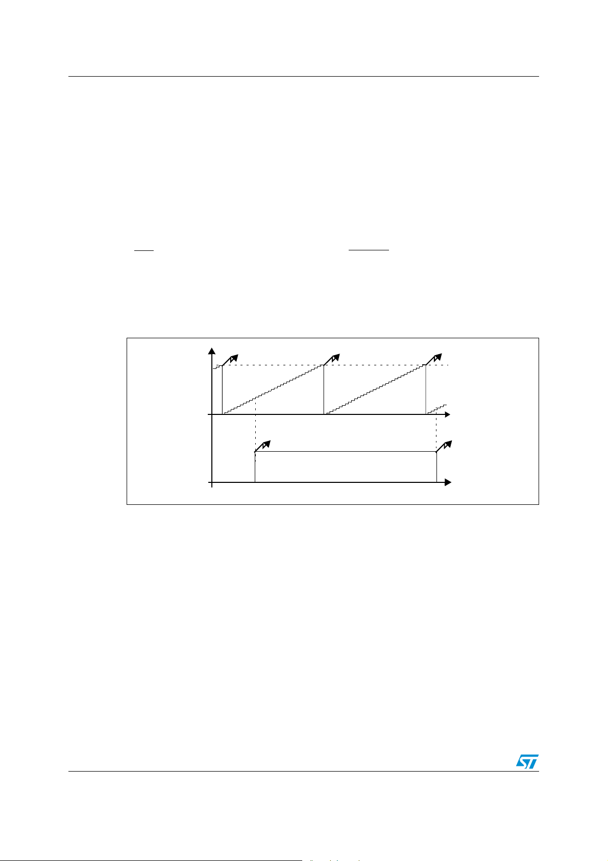
Based on Figure 7, it is possible to draw the following mathematical relationship:
t
H
= ((250-Capture 1)+Capture 2+250*(N-1))*
2
32
f
OSC
N>0
(3.3)
where t
represents the Hall sensor signal period, Capture 1 and Capture 2 indicate the
H
values of Counter 1 at the edges of the Hall sensor signal and N is the number of LTTB1
interrupt events between the two Hall sensor output transitions taken into account.
Figure 7. Hall sensor signal semi-period measuring (N>0)
LTT B 1 I n t
LTTB1 Int LTTB1 Int
249
Counter 1
Capture 1
Capture 2
t
LTIC Int
LTIC Int
Hall sensor
output
t
10/38
Page 11
AN2281 Implementation on the ST7LITE35 microcontroller
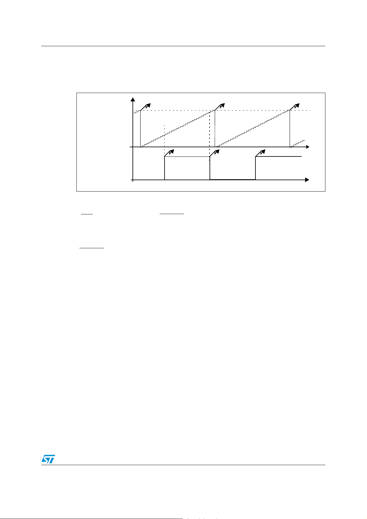
The relationship (3.3) is valid only under the condition N>0 and, then it can not be used to
measure frequencies higher than 500Hz. In this case the formula to be used, as can be
deduced from Figure 8, is the (3.4):
Figure 8. Hall sensor signal semi-period measuring (N=0)
LTT B 1 I n t
LTTB1 Int
249
Capture 2
Counter 1
Capture 1
LTIC Int
Hall sensor
output
t
H
= (Capture 2-Capture 1)*
2
32
f
OSC
Please note that in both (3.3) and (3.4) t
32
f
OSC
that is 4µsec at 8 MHz f
OSC
.
LTIC Int
LTIC Int
(3.4)
/2 is computed with a resolution equal to:
H
t
t
11/38
Page 12
Implementation on the ST7LITE35 microcontroller AN2281
You can observe that, in order to measure the Hall sensor semi-period correctly, the LTIC
and LTTB1 ISRs must be executed by the microcontroller core in the same order in which
the related interrupts events occurred. This would normally happen if no other interrupts
service routines are executing. However in our software, a third interrupt source is enabled
(PWM update event), so a potentially erroneous situation could arise due to the interrupt
priority mechanism.
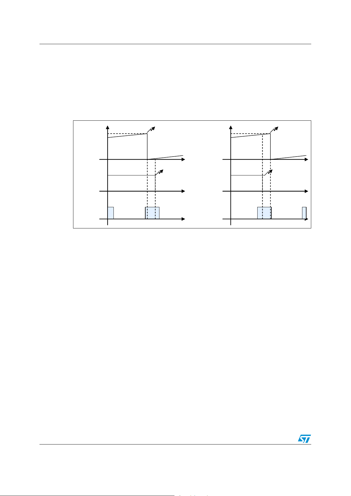
Figure 9 describes two possible situations:
Figure 9. Multiple interrupt pending situation
249
Counter 1
LTTB1
Captured
value << 125
LTIC Int
249
Counter 1
t
LTTB1
Captured
value >> 125
t
LTIC Int
Hall sensor
output
t
t
PWM OVF ISR execution
t
PWM OVF ISR execution
t
Due to the higher interrupt priority of LTIC with respect to LTTB1, in both cases the LTIC ISR
is executed before LTTB1 ISR.
In this case, the value stored in the LTICR is used to reconstruct the correct sequence: if the
content of the LTICR is lower than 125, it is assumed that the LTTB1 event occurred just
before a LTIC event so that the Lite Timer overflow counter must be incremented before the
semi-period computation. On the contrary, if the LTICR contains a value higher than 125, it
is assumed that the LTIC occurred just before a Lite timer overflow (LTTB1 event). In this
case, the overflow counter must not be incremented before the semi-period computation but
it will be taken into account at the next LTIC event.
12/38
Page 13

AN2281 Application schematics
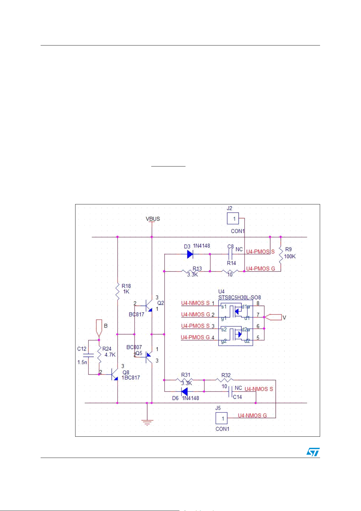
4 Application schematics
Figure 10 shows the application schematic:
Figure 10. Proposed reference schematic
VBUS
R9
100K
C11
1.5n
8
4 5
2
3
C1
1uF
ICCDATA
ICCCLK
RESET
C
R25
4.7K
2
Q9
U1
Vin
Vout
NC1 NC
GND1
GND3
GND2
GND4
78L05B
Hall sensor output
R19
1K
BC817
2
Q6
2
3
1
BC817
BC807
1
+5V
7
6
C2
1uF
+5V
R1
U
4.7K
V
+5V
D4
1N4148
R15
3.3K
U5-NMOS S
U5-NMOS GU3-NMOS G
U5-PMOS SU3-PMOS S
U5-PMOS G
R33
3.3K
W
J3
1
CON1
C9
NC
U5-PMOS S
R16
10
U5
STS8C5H30L-SO8
d1as1
2
g1
d1
3
s2
d2a
4 5
g2 d2
R34
10
U5-NMOS S
NC
C15
J6
U5-NMOS G
1
CON1
C4
10nF
3
Q3
1
1
3
D7 1N4148
+5V
RESET
R2
1K
D1
A
C10
R23
4.7K
1.5n
BC817
2
C3
SW1
0.01uF
1 2
+5V
R3
13
POT1 - 10K
LED
Q7
2
C6
100n
D2 1N4148
R11
BC817
2
BC807
2
3.3K
3
U3-NMOS S
1
Q1
U3-PMOS G
1
3
Q4
R29
3.3K
D5 1N4148
R17
1K
3
1
+5V
R4
13
POT2 - 10K
2
C5
100n
U3
STS8C5H30L-SO8
2
g1
3
s2
4 5
g2 d2
R30
10
NC
J4
C16
U2
100nF
1
VSS
2
VDD
3
RESET
4
PB0
5
PB1
6
PB2
7
PB3
8
PB4
9
PB5/AIN5
10
PB6/AIN6
19 20
OSC2 OSC1
J1
1
CON1
C7
U3-PMOS S
R12
U3-PMOS G U5-PMOS G
10
81
d1as1
7
d1
6
d2a
U3-NMOS S
C13
U3-NMOS G
1
CON1
18
LTIC2
17
PA1
16
ATPWM0
15
ATPWM1
14
ATPWM2
13
ICCDATA
12
ICCCLK
11
PA7
ST7LITE35
R10
100K
U V W
B
R24
C12
4.7K
1.5n
2
R18
3
Q8
1
1K
BC817
BC817
BC807
Hall sensor output
C
B
A
ICCDATA
ICCCLK
+5V
VBUS
D3
3
Q2
2
2
U4-NMOS S
1
U4-NMOS G
U4-PMOS S
U4-PMOS G
1
Q5
3
R31
3.3K
D6 1N 4148
1N4148
R13
3.3K
JP1
2
1
Supply Voltage
JP2
12
34
56
78
910
ICC Connector
J2
1
CON1
C8
NC
U4-PMOS S
R14
U4-PMOS G
10
U4
STS8C5H30L-SO8
d1as1
2
g1
d1
3
s2
d2a
4 5
g2 d2
R32
10
NC
U4-NMOS S
C14
J5
U4-NMOS G
1
CON1
81
7
6
As you can see in Figure 10, the proposed schematic has a logic section basically
consisting of the ST7FLITE35 microcontroller, and a power section including the threephase inverter.
JP3
1
2
3
4
5
6
HEADER 6
81
7
6
R7
100K
The power supply is consists only of an L7805 voltage regulator. The simplicity of this type
of solution limits the minimum operating voltage to almost 7V but you could obtain a lower
value by using a low drop voltage regulator (i.e. L4979D).
13/38
Page 14
Application schematics AN2281
4.1 Gate driving and dead time insertion circuit
Figure 11 shows in detail one of the three legs of the DC-AC inverter used in the reference
schematic, with the corresponding gate driving circuit. The description of this leg is valid for
the whole inverter.
In order to drive the U4 MOSFETs correctly and to avoid their contemporary conduction, the
signal coming from the microcontroller and applied at the base of bipolar transistor Q8 is,
first of all, level shifted by the emitter follower stage (Q8) and, then, a dead time is inserted
delaying the turn-on of the NMOS and PMOS devices and by making their turn-off
instantaneous.
Referring to the control signal (applied on point B in Figure 11) low-to-high transition and
assuming the P-channel MOSFET fully turned on when |V
dead time value by solving the following equation:
R13*C
t
PMOSin
V
BUS=VTHp
)
-
1-e
(
Figure 11. The dead time insertion circuit
|=VTH, you can compute the
GS
(4.1)
14/38
Page 15

AN2281 Application schematics
That leads to:
V
t
= R13*C
DTf
Likewise, for the high-to-low transition, it is possible to obtain:
t
= R31*C
DTf
where C
and NMOS and can be computed, with reference to the STS8C5H30L datasheet, as
C
+2C
iss
rss
The values of resistors R
to guarantee a minimum dead time in the worst condition (i.e. 7V supply voltage, high-to-low
control signal transition), of about 0.5 µsec.
PMOSin
.
and C
PMOSin
PMOSin
NMOSin
*1n
*1n
13
BUS
(
V
BUS-VTHp
V
BUS
(
V
BUS-VTHn
are, respectively, the equivalent input capacitance of PMOS
and R31 in the schematic in Figure 11 have been sized in order
)
)
(4.2)
(4.3)
15/38
Page 16

Library parameters AN2281
5 Library parameters
This paragraph describes the parameters used in the PMAC motor control library supplied
with this application note. All the command lines mentioned in this paragraph are included in
the PMAC_Param.h header file.
5.1 Phase synchronization and phase angle optimization
As discussed in Figure 2, every time an Hall sensor edge occurs, the phase of the sine wave
is refreshed, depending on the transition (high-to-low or low-to-high), with the phase angle Φ
or with Φ+Π. Moreover, the Hall sensor signal semi-period is stored so that the sine wave
frequency can be computed by averaging the last 4 semi-period measurements.
The tuning of the phase angle Φ is extremely important and it can enormously effect the
efficiency of the system. Two different solutions for phase angle optimization are possible
using the library supplied with this application note:
5.1.1 Phase angle tuned by Pot2
If the command line:
#define PHASE_READING_FROM_POT2
is not commented, the phase angle is read by the potentiometer Pot2. The minimum and
maximum available phase angles are configurable by definition statements:
#define MIN_PHASE (u16) xxx //in 360°/65535 unit (180° <=> 32768)
#define MAX_PHASE (u16) xxx //in 360°/65535 unit (180° <=> 32768)
5.1.2 Phase angle as a function of frequency
If the command line:
#define PHASE_READING_FROM_POT2
is commented out, the phase angle is computed as a linear function of the rotor speed
following the relationship illustrated in Figure 12:
Figure 12. Phase angle vs speed relationship
Phase angle
PH_AT_HIGHSPEED
PH_AT_LOWSPEED
PH_LOWSPEED
PH_AT_HIGHSPEED, PH_AT_LOWSPEED (in 360°/65535 unit), PH_LOWSPEED and
PH_HIGHSPEED (in rpm) are configurable in the PMAC_Param.h header file.
16/38
PH_HIGHSPEED
Speed
Page 17

AN2281 Library parameters
5.2 Start-up phase parameters
The motor start-up procedure implemented in the library presented in this application note
basically consists of two different phases:
● Rotor alignment phase
● Sinusoidal three-phase voltage ramp-up
5.2.1 Rotor alignment phase
This phase pre-positions the rotor in order to put it in a known position. This allows the
proper alignment of the statorical flux during motor start-up, avoiding any unwanted rotor
vibrations. Moreover, putting the rotor in a known position causes the current waveform
during the motor start-up to be repetitive and deterministic, and thus easily adjustable. In
spite of all this, in some applications, it can be useful not perform the alignment phase. This
usually produces a higher and more uncontrolled current but it can lead to a faster ramp-up
of the motor.
In the library supplied with this application note, you can disable or enable the rotor
alignment by commenting the command line in or out.
#define ROTOR_ALIGNMENT
The rotor pre-positioning is achieved by applying a linearly increasing voltage (starting from
zero volts) to one of the three phases of the motor while the other two are grounded.
The two command lines:
#define ALIGNMENT_DURATION xxx //Alignment duration in msec
#define FINAL_DUTY xxx //Final duty cycle in 1/255 units
//(85 <=> 33%)
set the alignment phase duration and the final duty cycle (normally it should not exceed
33%).
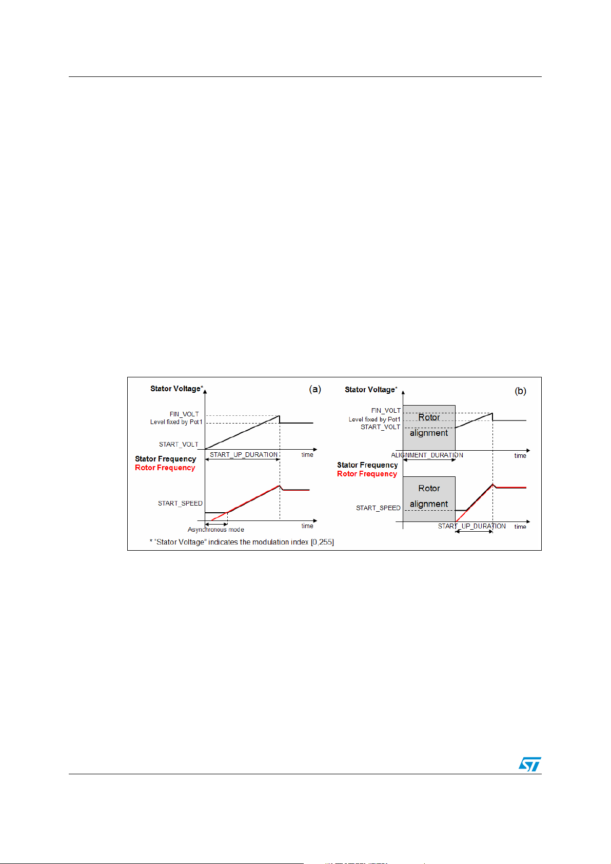
5.2.2 Sinusoidal three-phase voltage ramp-up
This procedure initializes the sinusoidal three-phase voltage generation and, in order to
reduce the start-up motor current, carries out a linear increase of the sine amplitude. The
command lines:
#define START_VOLT xxx // in 1/255 unit. 255 <=> maximum
// modulation index
#define START_SPEED xxx // in rpm
allow to you initialize the three-phase sinusoidal voltage amplitude and frequency. Note that
statorical frequency initialization is necessary because the self-synchronization algorithm
discussed in Section 2 can work properly only if the rotor frequency f* can be measured.
The initialized value of statorical frequency will be, therefore, applied to the motor until a
valid f* measurement has been performed.
17/38
Page 18
Library parameters AN2281
If the alignment phase has been performed,
#define START_PHASE xxx //expressed in 360°/65535
also initializes the phase of the sine wave so that the stator and rotor magnetic fields can be
synchronous starting from the first electrical period.
Moreover, the command lines
#define START_UP_DURATION xxx // in msec
#define FIN_VOLT xxx // in 1/255 units
set the sine wave amplitude at the end of the ramp-up and the ramp-up duration.
5.2.3 Open loop driving mode
Once the voltage ramp-up is over, open loop driving mode allows you adjust the amplitude
of the sinusoidal three-phase voltage applied to the motor using potentiometer Pot1.
The minimum and maximum amplitudes are definable and the related command lines are:
#define MAX_VOLTAGE xxx // Expressed in 1/255 units
#define MIN_VOLTAGE xxx //Expressed in 1/255 units
Figure 13 summarizes the basics of open loop driving mode:
Figure 13. Open loop start-up with (b) and without (a) rotor alignment phase
5.2.4 Closed loop driving mode for speed regulation
Closed loop driving mode includes a PI regulator acting on the amplitude of the three-phase
voltage for speed regulation. You set the target speed using potentiometer Pot. The
minimum and maximum target speeds are definable by command lines:
#define MIN_SPEED xxx //in rpm
#define MAX_SPEED xxx // in rpm
You can optimize the dynamic response of the system by acting on the sampling time and
the proportional and integral constants of the PI regulator in following command lines:
#define SAMPLING_TIME xxx //in msec
#define kp xxx
#define ki xxx
18/38
Page 19

AN2281 Library parameters
With the purpose of avoiding too strong a response by the PI regulator at the end of the
motor start-up, when the error between target speed and measured speed could be high, PI
regulation is enabled (and ramp-up ended) if, during the voltage ramp-up the actual speed
of the rotor is higher than an established threshold speed defined by:
#define CL_SPEED_VALIDATION xxx // in rpm
The control system, therefore, starts the motor as already described for open loop and it
enables the PI regulator either at the end of the start-up or when rotor reaches the speed
CL_SPEED_VALIDATION. Figure 14 summarizes the closed loop start-up strategy.
Figure 14. Closed loop start-up with (b) and without (a) rotor alignment phase
19/38
Page 20

Getting started with the ST7FLITE35-based PMAC motor control system AN2281
6 Getting started with the ST7FLITE35-based PMAC
motor control system
Follow this procedure to perform a system evaluation and be able to get started quickly
running your own motor.
6.1 Hardware connections
To start a 12V PMAC motor with the system presented in this application note, please
connect, with reference to Figure 9:
● the three phases of the motor to connector JP3-1,2,3
● the Hall sensor supply voltage, output and ground, respectively, to connector JP3-4,5,6
● the 12V supply voltage to connector JP1 (the negative pole to JP1-1)
6.2 Development tools
This section presents the available material that is needed to start working with the
ST7FLITE35 and the PMAC software library discussed in this document.
6.2.1 Integrated development environments (IDE)
Different IDE interfaces are available for free: ST proprietary's STVD7 (free download
available on internet: www.st.com), or third party IDE (e.g. Softec Microsystems' STVD7 for
InDART-STX).
The software library presented in this document has been compiled using Cosmic C
compiler (ver. 4.5c) launched with Softec STVD7 version 3.10. Please note that the 16K
limited free version of Cosmic compiler is able to compile the software library.
20/38
Page 21

AN2281 Getting started with the ST7FLITE35-based PMAC motor control system
Figure 15. Softec STVD7 ver3.10 development tool
6.2.2 Real time emulators
Two types of real-time development tools are available for debugging applications using
ST7FLITE35:
● In-circuit debugger from Softec (sales type: STXF-INDART/USB).The inDART-STX
from Softec Microsystems is both an emulator and a programming tool. This is
achieved using the In-circuit debug module embedded on the MCU. The real-time
features of the Indart include access to working registers and 2 breakpoint settings.
However trace is not available.
● ST7MDT10-EMU3. Full-featured emulator: real-time with trace capability, performance
analysis, advanced breakpoints, some logic analyzer capabilities,... You can also use it
as a programming tool with the ICC ADDON module, which is included with the
emulator. This ICC-ADDON module allows you to do In-Circuit-Debugging with STVD7.
6.2.3 Programmers
In order to program an MCU with the generated S19 file, output of the compilation, you
should also install the ST Visual Programmer software (available on ST website
www.st.com) and use a dedicated hardware programming interface (STICK programmer for
In-Circuit-Programming, for instance). The Visual Programming tool provides an easy way to
erase, program and verify the MCU contents.
Please note that the inDART-STX from Softec Microsystems is also a programming tool
(installation of DataBlaze Programmer software is required).
21/38
Page 22

Getting started with the ST7FLITE35-based PMAC motor control system AN2281
Figure 16. ST7 Visual programmer development tool
6.3 Library source code
6.3.1 Software downloads
The complete source files are available for free on the ST website as a zip file in the
Technical Literature section.
Note: Important: It is highly recommended to check for the latest releases of the library before
starting a new development, and to verify the release notes on ST’s website from time to
time in order to keep up-to-date about new features that might be useful for your project.
6.3.2 File structure
Once the files are unzipped, the following library structure is created.
Figure 17. The library structure
\sources
\Debug
\Release
To produce the target .S19 file, you should open the ST7VD workspace "PMAC_Lite.stw"
and compile the project by pressing the "Rebuild All" button of the ST7VD development tool.
22/38
Page 23

AN2281 Getting started with the ST7FLITE35-based PMAC motor control system
Two different sets of compiler and linker options (Debug and Release) can be handled by
the tool depending on the development stage.
6.4 How to set the library parameters to run a PMAC motor for the first time
To run a 12V PMAC motor with the motor control system described in this document, you
first need do some configuration to the software library. In the PMAC_Param.h header file,
set the number of motor pole pairs in the command line
#define POLES_PAIRS_NUMBER x
Then, you need to find out the optimum phase angle (an oscilloscope with a current probe
is necessary). To do this, you should:
● Enable the tuning of phase angle via the Pot2 potentiometer and set the minimum and
maximum angle respectively at 0 and 360°:
#define MIN_PHASE (u16) 0 //in 1/65535 unit 180° <=> 32768
#define MAX_PHASE (u16) 65535 //in 1/65535 unit 180° <=> 32768
●
Select open loop driving mode using this define:
#define DRIVING_MODE OPEN_LOOP
and setting the minimum and maximum voltages between 0% and 100%:
#define MAX_VOLTAGE 255
#define MIN_VOLTAGE 0
●
Disable V/F curve limitation
● Disable the rotor alignment phase
● Configure the start-up phase parameters, initially disabling the alignment phase and
fixing the ramp-up parameters as follows:
#define START_SPEED 400 //in rpm
#define START_UP_DURATION 500 // in msec
#define START_VOLT 25 // in 1/255 unit
#define FIN_VOLT 130 // in 1/255 unit
●
Adjust potentiometer Pot1 to about 50%
After you have made these settings, you should compile the software library and program
the microcontroller.
23/38
Page 24

Getting started with the ST7FLITE35-based PMAC motor control system AN2281
6.4.1 Determining the phase angle and optimizing the start-up parameters
After device programming, once the ICC cable has been removed, microcontroller begins to
execute the firmware and motor should start moving. As earlier discussed, the value of
phase angle Φ can greatly influence the efficiency of the system so that a wrong value of
could even prevent the motor from starting. For this reason, Pot2 should be slowly turned
(starting from 0% position) until motor start running and, then, the phase angle should be
finely tuned in order to increase the motor efficiency (that is reducing the current at fixed
speed). This can be easily achieved by changing the MIN_PHASE and MAX_PHASE
parameters with the purpose of progressively incrementing the resolution of potentiometer
Pot2.
It could happen that, even if you slowly turn the Pot2 potentiometer from the 0% position to
the 100% position, the motor does not start spinning. In this case, the voltage fed to the
motor may not be sufficient and you should increase it slightly by turning the Pot1
potentiometer towards the 100% position. While doing this, you should monitor one of the
three phase currents to be sure it does not exceed the absolute maximum ratings of the
motor. Then repeat the procedure for optimum phase identification.
Once the motor has started running, you should then try to determine the optimum phase
angle versus frequency characteristic in order to find out the best PH_AT_HIGHSPEED,
PH_AT_LOWSPEED, PH_LOWSPEED and PH_HIGHSPEED parameters.
You should then disable “phase angle read by Pot2”.
24/38
Page 25

AN2281 Conclusion and results
7 Conclusion and results
A low-voltage three-phase AC permanent magnet motor (PMAC or BLAC) control system
has been developed using ST7FLITE35. Some concluding remarks concerning the CPU
load and the code memory size are given below. This is followed by a series of oscilloscope
captures illustrating the proper behavior of the system.
7.1 Motor control related CPU load
The CPU load computation has been performed when using closed loop driving mode, with
Ph/f linear relationship enabled and V/f limitation disabled. The system was driving a 4 polepair motor, running at 10,000 rpm.
The most important contributors to the CPU load were these motor control tasks:
● Sine wave generation. As discussed in Section 3.1, the sine wave update is
performed in the 12-bit autoreload timer overflow interrupt service routine
(LART_OVF1_IT_Routine). When the three PWM duty cycles are not computed, the
execution time of this interrupt service routine is about 4 µsec. while, when the three
duty cycles are updated, the execution time is around 27.5 µsec. Considering then, that
a interrupt is generated every 64 µsec., the contribution of this task to the CPU load is
equivalent to:
4+27.5
2*64
● Hall sensor signal semi-period measurement. As earlier discussed, this task is
performed in the Lite Timer Input Capture interrupt service routine. Considering a 4
pole-pair motor running at 10,000 rpm, the incoming Hall sensor signal frequency is
666.7Hz. One LTIC interrupt is therefore generated every 750µsec. Since the execution
time of this routine, is around 26.5 µsec., the contribution of this task to the CPU load,
under the described conditions, is equivalent to 3.5%.
● PI regulation. Assuming a sampling time of 25msecs and considering that the
execution time of this routine is, in worst case conditions, around 150µsec, the
contribution of PI regulation to the CPU load is less than 1% and therefore negligible.
● Period to frequency conversion. In order to guarantee a high level of
synchronization, sine wave frequency should be computed, starting from the measured
semi-periods, at least once per Hall sensor period.
*100=24.6%
Considering that, for a motor with 4 pole pairs running at 10,000 rpm, the incoming Hall
sensor signal frequency is 666.7Hz and that the average time required for executing the
time to frequency conversion is around 222µsec, the contribution of this task to the CPU
load is given by
-4
222*10
*666.7=14.8%
Under the described conditions, the overall CPU load is then
CPU load = 24.6 + 3.5 + 14.8 = 42.9%
25/38
(7.1)
Page 26

Conclusion and results AN2281
7.2 Code memory size
Ta bl e 1 summarizes the size of the compiled code, in terms of program and RAM memory,
in different settings situations and with "Release" compiler options:
Table 1. RAM and program memory code size
Settings
Open loop, rotor alignment phase disabled, phase angle read
by potentiometer, V/f limitation disabled
Open loop, rotor alignment phase enabled, Phase angle
computed from Ph/f relationship, V/f limitation enabled
Closed loop, rotor alignment phase disabled, phase angle read
by potentiometer, V/f limitation disabled
Closed loop, rotor alignment phase enabled, Phase angle
computed from Ph/f relationship, V/f limitation enabled
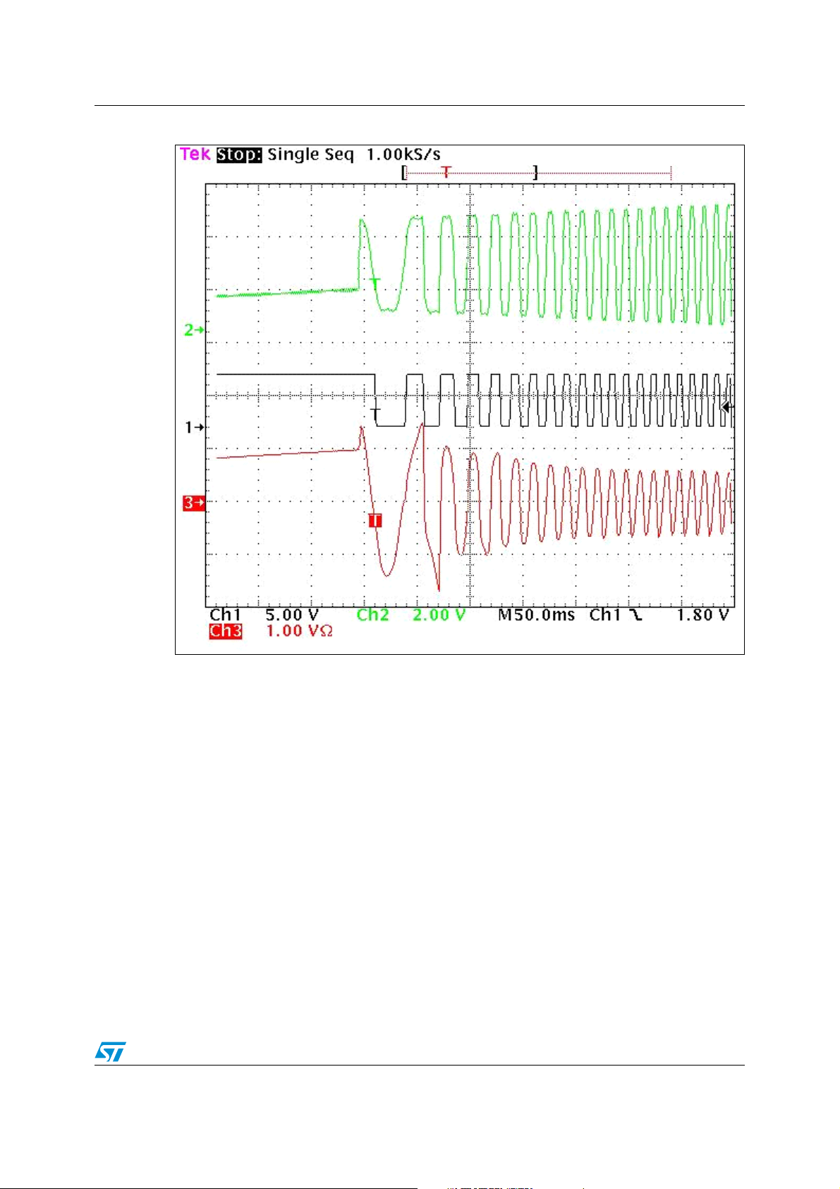
7.3 Example oscilloscope captures
Figure 17 and Figure 18. show a typical start-up in open loop. The capture shows the signal
on pin ATPWM0 (filtered so that only the modulating signal is visible), the Hall sensor output
and the current flowing through phase W of the motor (see Figure 9). The rotor alignment is
enabled in Figure 17 and it is possible to observe its final phase (before the sine wave starts
to be generated) while it has been disabled in the start-up shown in Figure 18..
Figure 19. illustrates a typical start-up in closed loop. Please observe that sinus amplitude is
modulated every SAMPLING_TIME (75) milliseconds in order to make the speed constant.
Finally, Figure 20. shows typical steady-state behavior.
Program
memory size
1470 b 55 b
2027 b 63 b
1859 b 66 b
2438 b 76 b
RAM size
26/38
Page 27
AN2281 Conclusion and results
Figure 18. Open loop start-up with rotor alignment enabled
27/38
Page 28

Conclusion and results AN2281
Figure 19. Open loop start-up without rotor alignment
28/38
Page 29

AN2281 Conclusion and results
Figure 20. Closed loop start-up
29/38
Page 30

Conclusion and results AN2281
Figure 21. Typical steady-state conditions
30/38
Page 31

AN2281 List of software functions and interrupt service routines
Appendix A List of software functions and interrupt
service routines
My_functions.c Module
Set_Spinning_Direction
Description: This function allows you to set the rotation direction of the motor before the
start-up procedure
Input: Value CW or CCW ("direction" type has been defined in My_functions.h
header file)
Returns: None
Caution: This function must be called when the motor is stopped, before the start-up
procedure. Calling the function while the motor is running could cause
damage to the motor.
Soft_Start
Description: This function carries out a soft motor start up by performing a linear
Input: None
Returns: None
See also:: Start-up procedure description in Section 5.2
Note: start_up_on_going variable is equal to 1 if soft start is on-going, 0 if it is
DoRotorAlignment
Description: This function performs the rotor alignment by exciting the motor phase W
Input: None
Returns: None
Caution: The function is compiled only if rotor alignment phase is enabled
Duration: ~ ALIGNMENT_DURATION.
See also:: Start-up procedure description in Section 5.2
DoMotorControl
increase of the three-phase sinusoidal voltage.
over.
(see Figure 9) and keeping the other two at ground
Description: This function performs a closed loop speed control. It utilizes a PI
(proportional and integral) regulation algorithm to determine the most
appropriate voltage value to get the expected rotor speed.
31/38
Page 32

List of software functions and interrupt service routines AN2281
Input: Target speed in u16 format. Data returned by Get_Target_Speed function
can be directly used as input data
Returns: None
Caution: The function is compiled only if closed loop driving mode is defined.
Duration: The PI routine average execution time is strongly dependent on the error
between actual and target speed. In worst-case conditions (high error), the
routine duration is equal to 157 µsec.
See also:: Section 5.2.4
Get_Rotor_Freq
Description: This function computes the stator frequency to be applied to the motor. At
start-up, the function returns the stator frequency initialization value. As
soon as the first valid Hall sensor semi-period measurement has been
performed and until the fourth semi-period measurement has been
completed, the function returns the last measured rotor frequency. After the
fourth semi-period measurement has been carried out, the average rotor
frequency (based on last 4 measurements) is returned.
Input: None
Returns: Stator frequency with 0.1192Hz resolution.
Duration: 222 µsec in steady state
Freq_computing
Description: This function is called by Get_Rotor_Freq function, it performs the division
Input: Hall sensor semi-period (u16 format with 16µsec resolution).
Returns: Electrical frequency, defined by the formula:
Duration: 204 µsec.
for converting the Hall sensor signal semi-period measurements into a
frequency (0x3FFFF/period).
Electrical frequency = Rotor speed (in rpm)* Number of Pole pairs/60
with 0.1192Hz resolution.
32/38
Page 33

AN2281 List of software functions and interrupt service routines
lt.c Module
LT_TB1_IT_Routine
Description: Lite Timer counter 1 overflow interrupt service routine.
The Lite Timer is configured so that this interrupt occurs every 1 msec., two
variables are incremented in this interrupt service routine. Then "counter"
variable is used for Hall sensor signal semi-period measurement and the
"timebase_1ms" variable is used as 1 msec time base.
Input: None
Returns: None
Duration: 4.35µsec
LT_ICAP_IT_Routine
Description: Lite Timer input capture interrupt service routine.
Hall sensor signal semi-period measurement is performed in this routine.
Moreover, depending on the logical value of the Hall sensor signal, the
phase of the PWM modulated sinusoidal voltage output on pin ATPWM0
(phase C) is forced with phase angle value Φ or with Φ+π. Finally, the
watchdog timer is enabled/refreshed so that, if no Hall sensor edges occur
in 127msec (corresponding to an electrical frequency of less than 4 Hz), a
hardware reset is generated.
Figure 22 shows the flowchart of this interrupt service routine.
Input: None
Returns: None
Duration: The average duration is 26.15 µsec.
33/38
Page 34

List of software functions and interrupt service routines AN2281
Figure 22. LT_ICAP_IT_Routine block diagram
LT_ICAP_IT_Routine
old_capture = new_capture
new_capture=LTICR
Ye s
Is LT TB1 IT
flag set?
OVF counter ++
@ next LTIC event
Ye s N o
LTICR > 120?
OVF counter++
Hall sensor semiperiod computing
No
and storing
Ye s N o
Sine phase = Phase_angle
Enable/Refresh Watchdog
Is Hall sensor
signal level high?
Sine phase = Phase_angle + 180°
IRET
34/38
Page 35

AN2281 List of software functions and interrupt service routines
lart.c Module
LART_OVF1_IT_Routine
Description: 12-bit autoreload timer overflow interrupt service routine.
Sine waveform updating is performed in this routine once every two PWM
periods. A look-up table with 256 8-bit entries for storing sine values has
been used. Figure 23 shows the flowchart of this interrupt service routine.
Input: None
Returns: None
Duration: The average duration is 15.75 µsec.
35/38
Page 36

List of software functions and interrupt service routines AN2281
Figure 23. LART_OVF1_IT_Routine block diagram
LART_OVF1_IT_Routine
Negate scaled value
Update Sine?
Integrate frequency to
compute the sine phase
Access look-up table using
phase as pointer
Scale according with sine
amplitude value
Ye s
Negative sine
semiperiod?
Update DCRO register
Add 120° to the sine phase
No
Ye s
No
Redo calculations
for DCR1 register
Add 120° to the sine phase
Redo calculations
for DCR2 register
36/38
IRET
Page 37

AN2281 Revision history
8 Revision history
Table 2. Document revision history
Date Revision Changes
28-Mar-2006 1 Initial release.
37/38
Page 38

Revision history AN2281
r
Please Read Carefully:
Information in this document is provided solely in connection with ST products. STMicroelectronics NV and its subsidiaries (“ST”) reserve the right to make changes, corrections,
modifications or improvements, to this document, and the products and services described herein at any time, without notice.
All ST products are sold pursuant to ST’s terms and conditions of sale.
Purchasers are solely responsible for the choice, selection and use of the ST products and services described herein, and ST assumes no liability whatsoever relating to the
choice, selection or use of the ST products and services described herein.
No license, express or implied, by estoppel or otherwise, to any intellectual property rights is granted under this document. If any part of this document refers to any third party
products or services it shall not be deemed a license grant by ST for the use of such third party products or services, or any intellectual property contained therein or considered
as a warranty covering the use in any manner whatsoever of such third party products or services or any intellectual property contained therein.
UNLESS OTHERWISE SET FORTH IN ST’S TERMS AND CONDITIONS OF SALE ST DISCLAIMS ANY EXPRESS OR IMPLIED WARRANTY WITH RESPECT TO THE
USE AND/OR SALE OF ST PRODUCTS INCLUDING WITHOUT LIMITATION IMPLIED WARRANTIES OF MERCHANTABILITY, FITNESS FOR A PARTICULAR
PURPOSE (AND THEIR EQUIVALENTS UNDER THE LAWS OF ANY JURISDICTION), OR INFRINGEMENT OF ANY PATENT, COPYRIGHT OR OTHER INTELLECTUAL
PROPERTY RIGHT.
UNLESS EXPRESSLY APPROVED IN WRITING BY AN AUTHORIZE REPRESENTATIVE OF ST, ST PRODUCTS ARE NOT DESIGNED, AUTHORIZED OR WARRANTED
FOR USE IN MILITARY, AIR CRAFT, SPACE, LIFE SAVING, OR LIFE SUSTAINING APPLICATIONS, NOR IN PRODUCTS OR SYSTEMS, WHERE FAILURE OR
MALFUNCTION MAY RESULT IN PERSONAL INJURY, DEATH, OR SEVERE PROPERTY OR ENVIRONMENTAL DAMAGE.
Resale of ST products with provisions different from the statements and/or technical features set forth in this document shall immediately void any warranty granted by ST fo
the ST product or service described herein and shall not create or extend in any manner whatsoever, any liability of ST.
ST and the ST logo are trademarks or registered trademarks of ST in various countries.
Information in this document supersedes and replaces all information previously supplied.
The ST logo is a registered trademark of STMicroelectronics. All other names are the property of their respective owners.
© 2006 STMicroelectronics - All rights reserved
Australia - Belgium - Brazil - Canada - China - Czech Republic - Finland - France - Germany - Hong Kong - India - Israel - Italy - Japan - Malaysia - Malta - Morocco - Singapore
- Spain - Sweden - Switzerland - United Kingdom - United States of America
STMicroelectronics group of companies
www.st.com
38/38
 Loading...