


AN2271
APPLICATION NOTE
Ekey-Udisk solution
Introduction
This document describes a firmware implementation for an Ekey-Udisk device based on
ST72651.
The software is divided into 3 parts:
● USB management: the main USB operations are managed by a USB library with USB
hardware, which is not the focus in this documentation. For further information on this
subject, please refer to the ST7 USB software library documentation.
● NAND Flash interface: this part software is migrated from PFD solution. How to
implement it is not mentioned in this documentation.
● Smart Card interface: this interface is implemented by timer and accords ISO7816-1,
2, 3.
December 2005 1/8
www.st.com
System Structure AN2271
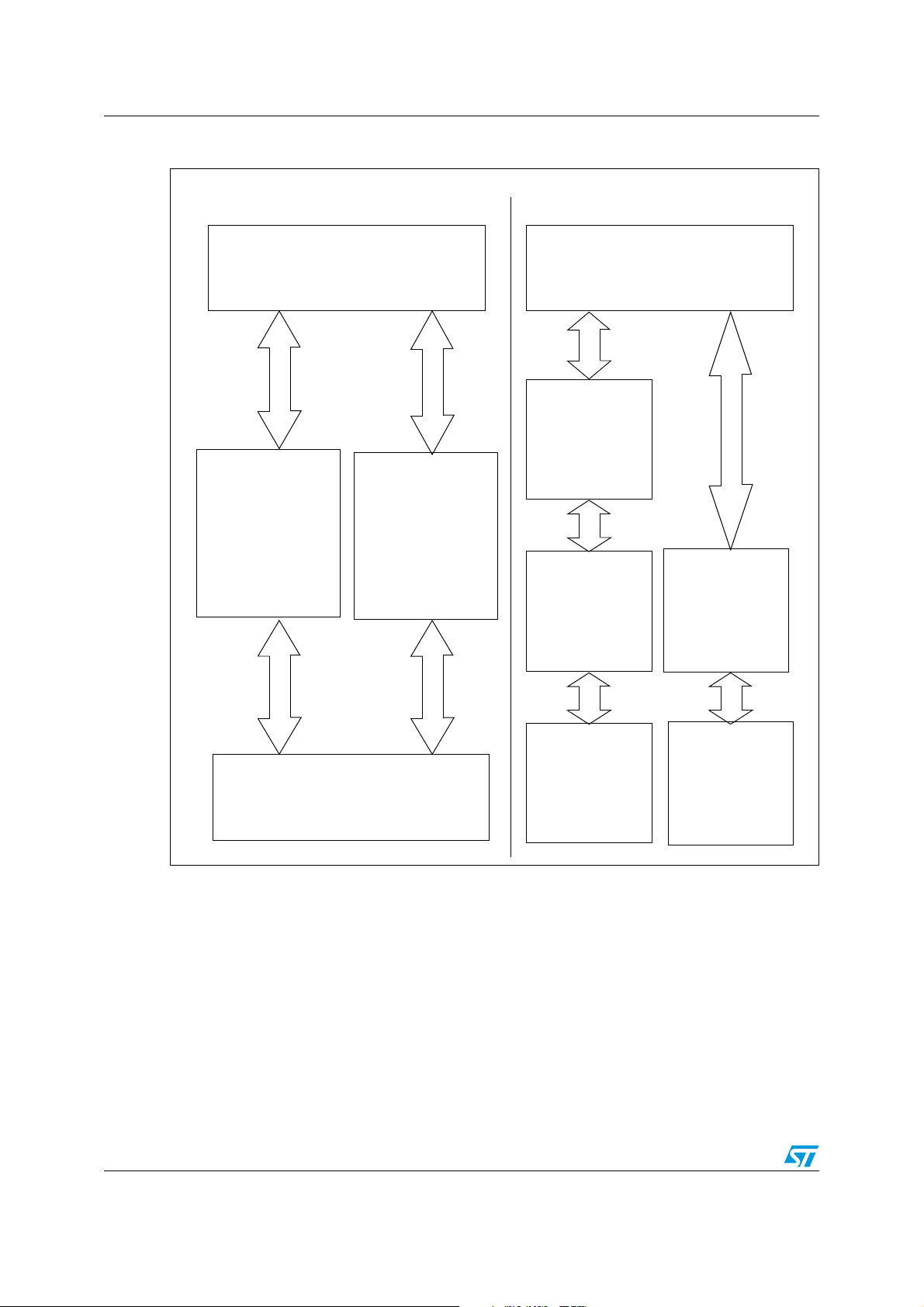
1 System Structure
PC SIDE
PC Application Software calls 2
interfaces through different driver
HID Interface
Mass Storage
Ekey Function
Udisk Function
Microsoft HID
driver
Microsoft Mass
Storage driver
Interface
DEVICE SIDE
Full Speed USB Lib
(Based on ST7 chip)
Process HID
Protocol
Process APDU
Protocol
Process BOT
RBC Protocol
Microsoft USB driver
2/8
ISO 7816 NAND Flash
Plugin
www.st.com
AN2271 System Diagram
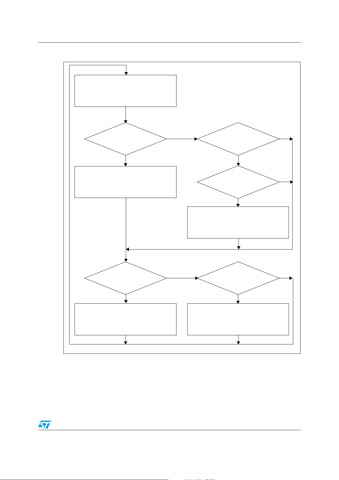
2 System Diagram
Main
Polling USB event
New HID data received?
Ye s
Parse APDU Request.
Set ETU timer interrupt.
Start communication with smart card.
New
BOT package
received?
Ye s
No
No
APDU
transaction is
on-going?
Ye s
APDU
transaction has
finished?
Ye s
Send back APDU result
Flash
operation has
finished?
Ye s
No
No
No
Flash operation
Send back BOT status
3/8

USB Interface AN2271
3 USB Interface
This solution uses a USB Composite Device to combine the Ekey and Udisk functions into
one USB device.
The Ekey function uses an HID protocol, and the Udisk function uses a Mass Storage
protocol. Both of these two functions use a Microsoft driver, so when an Ekey-Udisk device
plugs in, Windows2000/XP recognizes one USB composite device comprised of one HID
device and one Mass Storage device. No extra driver is needed.
The USB interface for Udisk is traditional.
The USB interface for Ekey is shown below, and the PC Application Software can use this
data structure to communicate with Ekey through the HID driver.
Report ID (1 Byte) Message Length (1 Byte) Data (1-128 Bytes)
Enumerating a USB composite device with HID and a Mass Storage device is listed in the
file descript.c
According to the HID protocol, PC communication is configured in USER_USB_Setup() in
User_lib.c
Note: According to the limitation of the HID driver, in order to save time to send data to the device,
PC Application Software should select the correct Report ID based on the Message Length.
9 report types are provided for use with supporting lengths from 0x0f to 0x8f. If necessary,
additional descriptors can be created by modifying these to provide other report types.
Table 1. Report ID based on message length
ID Length Data Length
1 0x01~0x0f Data(0x01~0x0f bytes)
2 0x01~0x1f Data(0x01~0x1f bytes)
3 0x01~0x2f Data(0x01~0x2f bytes)
4 0x01~0x3f Data(0x01~0x3f bytes)
5 0x01~0x4f Data(0x01~0x4f bytes)
6 0x01~0x5f Data(0x01~0x5f bytes)
7 0x01~0x6f Data(0x01~0x6f bytes)
8 0x01~0x7f Data(0x01~0x7f bytes)
9 0x01~0x8f Data(0x01~0x8f bytes)
4/8

AN2271 NAND Flash Interface
4 NAND Flash Interface
This part firmware is migrated from the ST PFD solution, and for related applications, please
refer to the PFD application note.
This NAND Flash Interface provides two partitions where one is the Public Partition and the
other is the password-protected Security Partition.
Two types of NAND Flash (512B/page & 2kB/page) are supported. Other Flash formats can
be supported by modifying software.
5/8

Smart Card Interface AN2271
5 Smart Card Interface
This interface provides the user with a set of functions for using the Timer and I/O to
communicate with the smart card. It is composed of 3 files:
● HID_usb.c
● UARTT0.c
● Int_7265.c
The HID_usb.c file provides the protocol conversion from the HID protocol to the ISO7816
APDU protocol for the main loop program.
The UARTT0.c file implements the ISO7816 T0 protocol to communicate with the smart
card.
● CardPowerOn() function is called by HID_usb.c to provide a voltage to smart card
● CardSend() function is called by HID_usb.c to start a UART communication
● T0SendData() function is called by timer interrupt to send one bit at a set time
● T0ReceiveData() function is called by timer interrupt to receive one bit at a set time
The Int_7265.c file provides one timer interrupt management and one external interrupt
management to implement the ISO7816 T0 protocol.
● INT_TIM() function is coded to call T0SendData() function or T0ReceiveData() function
to receive or send one bit when a specific time is reached.
● INT_EI2() function is coded to start the timer when a UART start bit is detected.
The MCO pin of ST72651 is used to provide a clock signal to the smart card. The output of
the MCO pin is 6MHz. In this solution, it should reduce to 3MHz to use as smart card clock,
if the user wants another clock frequency, an external crystal could provide different clock.
The UsbVddf pin of ST72651 is used to provide Voltage to the smart card. The voltage
output by this pin is 3.3V, so this interface is 3.3V. If you want another voltage interface, you
should modify the I/O pins.
In this solution, the baud rate of the ISO7816 interface uses a default value of 8.064kbps. If
you require another baud rate, the timer value should be modified.
6/8

AN2271 Revision history
6 Revision history
Table 2. Document revision history
Date Revision Changes
02-Dec-2005 0.1 Initial release
05-Dec-2005 1.0
System flowcharts modified
Table 1 on page 4 added
7/8

Revision history AN2271
“THE PRESENT NOTE WHICH IS FOR GUIDANCE ONLY AIMS AT PROVIDING CUSTOMERS WITH
INFORMATION REGARDING THEIR PRODUCTS IN ORDER FOR THEM TO SAVE TIME. AS A
RESULT, STMICROELECTRONICS SHALL NOT BE HELD LIABLE FOR ANY DIRECT, INDIRECT OR
CONSEQUENTIAL DAMAGES WITH RESPECT TO ANY CLAIMS ARISING FROM THE CONTENT OF
SUCH A NOTE AND/OR THE USE MADE BY CUSTOMERS OF THE INFORMATION CONTAINED
HEREIN IN CONNECTION WITH THEIR PRODUCTS.”
Information furnished is believed to be accurate and reliable. However, STMicroelectronics assumes no responsibility for the consequences
of use of such information nor for any infringement of patents or other rights of third parties which may result from its use. No license is granted
by implication or otherwise under any patent or patent rights of STMicroelectronics. Specifications mentioned in this publication are subject
to change without notice. This publication supersedes and replaces all information previously supplied. STMicroelectronics products are not
authorized for use as critical components in life support devices or systems without express written approval of STMicroelectronics.
The ST logo is a registered trademark of STMicroelectronics.
All other names are the property of their respective owners
© 2005 STMicroelectronics - All rights reserved
STMicroelectronics group of companies
Australia - Belgium - Brazil - Canada - China - Czech Republic - Finland - France - Germany - Hong Kong - India - Israel - Italy - Japan -
Malaysia - Malta - Morocco - Singapore - Spain - Sweden - Switzerland - United Kingdom - United States of America
www.st.com
8/8
 Loading...