

Page 1

Introduction
High brightness LEDs are becoming a prominent source of light and often have better efficiency
and reliability than conventional light sources. While LEDs can operate from an energy source
as simple as a battery and resistor, most applications require an efficient energy source not
only for the reduction of losses, but also to maintain the brightness of the LED itself. For
applications that are powered from low voltage AC sources typically used in landscape lighting
or low voltage DC sources that may be used in automotive applications or to meet safety
requirements, high efficiency DC-DC converters configured for constant output current provide
a high efficiency driver that can operate over a relatively wide range of input voltages to drive
series strings of one to several LEDs
This application note describes a DC-DC converter circuit that can easily be configured to dri ve
LEDs at several different output currents and can be configured for either AC or DC input. The
circuit uses the L5973D monolithic step down converter configured to drive a series string of
LEDs in a constant current mode.
AN2259
APPLICATION NOT E
High intensity LED driver using the L5970D/L5973D
L5970D is a step down monolithic power switching regulator capable of delivering 1A while the
L5973D is able to deliver 2A at output voltages from 1.25V to 35V. Both devices use internal PChannel D-MOS transistors (with typical R
minimize the size of external components. An internal oscillator fixes the switching frequency
at 250kHz.
The brightness of the LED (Light Emitting Diode), or light intensity as measured in Lumens, is
proportional to the forward current flowing through the LED. Since the forward voltage drop of
the LED can vary from device to device it is important to drive the LEDs with a constant current
driver to be able to get good matching of the light output, especially when they are located side
by side where variations in light intensity are quickly noticed. A typical way to drive LEDs in the
constant current mode is to use a DC-DC converter configured to give a constant current
output. The circuit shown in Figure 7. uses the L5973D in a constant current configuration to
drive LEDs
of 250mΩ) as the switching element to
DS(on)
Rev 1.0
AN2259/1105 1/38
www.st.com
38
Page 2
AN2259
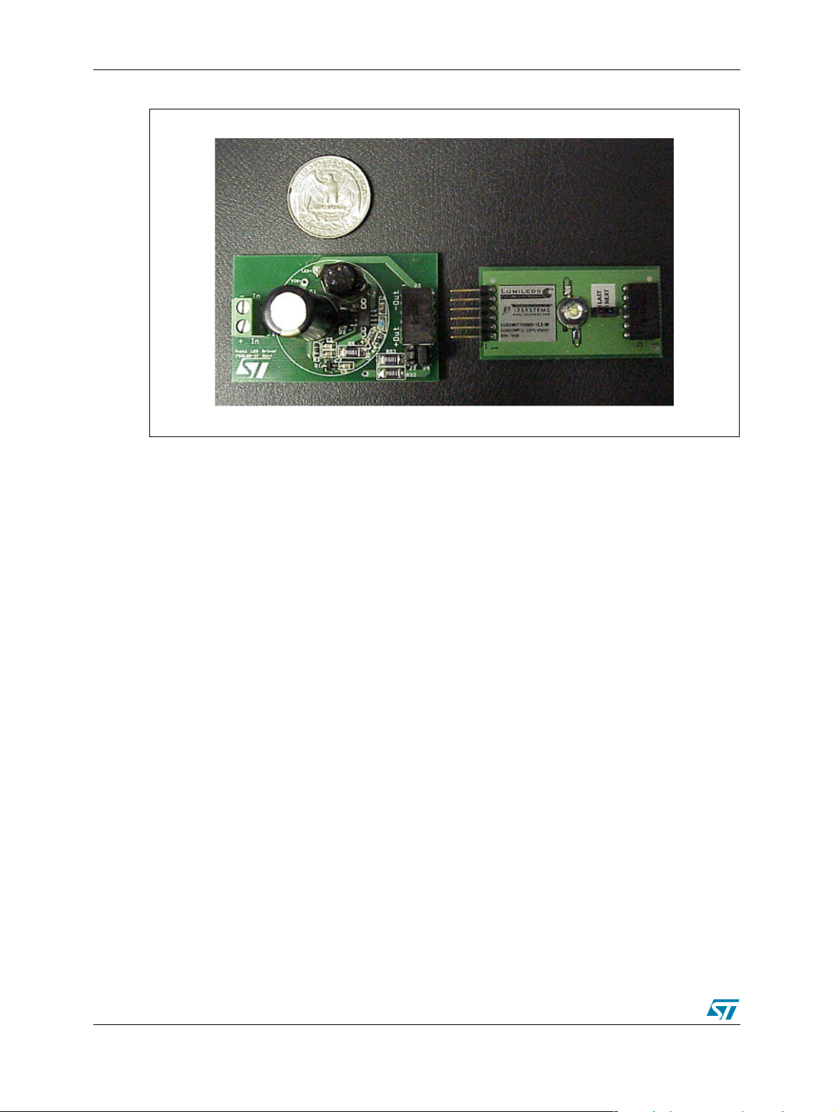
Figure 1. Board Layout
2/38
Page 3

AN2259
Contents
1 DESCRIPTION OF BOARD . . . . . . . . . . . . . . . . . . . . . . . . . . . . . . . . . . . . . . 6
2 INPUT CAPACITOR SELECTION . . . . . . . . . . . . . . . . . . . . . . . . . . . . . . . . . 7
3 CURRENT FEEDBACK LOOP . . . . . . . . . . . . . . . . . . . . . . . . . . . . . . . . . . . . 9
4 INDUCTOR SELECTION . . . . . . . . . . . . . . . . . . . . . . . . . . . . . . . . . . . . . . . 11
5 BOARD LAYOUT . . . . . . . . . . . . . . . . . . . . . . . . . . . . . . . . . . . . . . . . . . . . . 13
6 REFERENCE DESIGN VERSIONS . . . . . . . . . . . . . . . . . . . . . . . . . . . . . . . 16
7 REVISION HISTORY . . . . . . . . . . . . . . . . . . . . . . . . . . . . . . . . . . . . . . . . . . . 36
3/38
Page 4

AN2259
Figures
Figure 1. Board Layout. . . . . . . . . . . . . . . . . . . . . . . . . . . . . . . . . . . . . . . . . . . . . . . . 2
Figure 2. Current feedback . . . . . . . . . . . . . . . . . . . . . . . . . . . . . . . . . . . . . . . . . . . . 9
Figure 3. Ripple Current (One 1W LED). . . . . . . . . . . . . . . . . . . . . . . . . . . . . . . . . . 11
Figure 4. Ripple current (One 5W LED). . . . . . . . . . . . . . . . . . . . . . . . . . . . . . . . . . 12
Figu r e 5 . T o p side of Boar d ( n o t in sca le) . . . . . . . . . . . . . . . . . . . . . . . . . . . . . . . . 13
Figu r e 6 . Botto m side of Bo ard (no t in sca le) . . . . . . . . . . . . . . . . . . . . . . . . . . . . . . 13
Figure 7. Board Schematic. . . . . . . . . . . . . . . . . . . . . . . . . . . . . . . . . . . . . . . . . . . . 14
Figure 8. 12Vac Input 1W LED Driver Schematic . . . . . . . . . . . . . . . . . . . . . . . . . . 18
Figure 9. 12Vac Input 3W LED Driver Schematic . . . . . . . . . . . . . . . . . . . . . . . . . . 20
Figure 10. 12Vac Input 5W LED Driver Schematic . . . . . . . . . . . . . . . . . . . . . . . . . . 22
Figure 11. 6 to 12Vdc Input 1W LED Driver Schematic . . . . . . . . . . . . . . . . . . . . . . . 24
Figure 12. 6 to 12Vdc Input 3W LED Driver Schematic . . . . . . . . . . . . . . . . . . . . . . . 26
Figure 13. 6 to 12Vdc Input 5W LED Driver Schematic . . . . . . . . . . . . . . . . . . . . . . . 28
Figure 14. 6 to 24Vdc Input 1W LED Driver Schematic . . . . . . . . . . . . . . . . . . . . . . . 30
Figure 15. 6 to 24Vdc Input 3W LED Driver Schematic . . . . . . . . . . . . . . . . . . . . . . . 32
Figure 16. 6 to 24Vdc Input 5W LED Driver Schematic . . . . . . . . . . . . . . . . . . . . . . . 34
4/38
Page 5

AN2259
Tables
Table 1. Bill of Mata r ials . . . . . . . . . . . . . . . . . . . . . . . . . . . . . . . . . . . . . . . . . . . . . 15
Table 2. Components Changes For Different Configuration. . . . . . . . . . . . . . . . . . 16
Table 3. 12Vac Input 1W LED Driver Bill of Materials. . . . . . . . . . . . . . . . . . . . . . . 19
Table 4. 12Vac Input 3W LED Driver Bill of Materials. . . . . . . . . . . . . . . . . . . . . . . 21
Table 5. 12Vac Input 5W LED Driver Bill of Materials. . . . . . . . . . . . . . . . . . . . . . . 23
Table 6. 6 to 12Vdc Inp ut 1W LED Driv e r Bill of Mater ia ls . . . . . . . . . . . . . . . . . . . 25
Table 7. 6 to 12Vdc Inp ut 3W LED Driv e r Bill of Mater ia ls . . . . . . . . . . . . . . . . . . . 27
Table 8. 6 to 12Vdc Inp ut 5W LED Driv e r Bill of Mater ia ls . . . . . . . . . . . . . . . . . . . 29
Table 9. 6 to 24Vdc Inp ut 1W LED Driv e r Bill of Mater ia ls . . . . . . . . . . . . . . . . . . . 31
Table 10. 6 to 24Vdc Inp ut 3W LED Driv e r Bill of Mater ia ls . . . . . . . . . . . . . . . . . . . 33
Table 11. 6 to 24Vdc Inp ut 5W LED Driv e r Bill of Mater ia ls . . . . . . . . . . . . . . . . . . . 35
5/38
Page 6

1 DESCRIPTION OF BOARD AN2259
1 DESCRIPTION OF BOARD
The evaluation board shown in F igure 1. was designed so that it can be configured to accept
several different input voltages that are common for automotive and lighting applications. The
most common input voltages are 12V ac, 12Vdc (for automotive) and 24Vdc. The board also
allows the user to select the output current using the jumpers J2 and J4 on the board without
having to change any components on the evaluation board. The standard configuration of the
board includes a full wave bridge rectifier that is required for an AC input
6/38
Page 7

AN2259 2 INPUT CAPACITOR SELECTION
Vin
o
D
I
n
V
)
2
2
C
2 INPUT CAPACITOR SELECTION
For DC input, the input capacitor, C1, is selected based on its ripple current rating for the
capacitor. The ripple current is calculated based on its duty cycle as outlined below.
V
=
Where D = duty cycle
Vo = output voltage
Vin = input voltage
The RMS current through the capacitor therefore is:
22
DD2
⋅
ripple
µ= efficiency
DIo
−=
+
2
η
η
For an AC input voltage, the input capacitor is selected primarily to have enough capacity to
supply the LED between the peaks of the AC input. The capacitor must be selected so that the
minimum voltage at the input to the L5973D is maintained during each half cycle of the AC
input.
Vi
peak ⋅=
2
If the application is driving only one LED, the Vmin is determined by the minimum operating
voltage specification for the L5973D (4.4V). When driving more than one LED in series, the
minimum input voltage is determined by the output voltage and the minimum differential input to
output voltage for the regulator (the drop out voltage). In this case V
+ V
DO
= (x * Vf) + (I
min
out
* R
sense
Where: x = number of LED in series
= forward voltage of one LED
V
f
= LED drive current
I
o
= Drop out voltage
V
DO
The capacitor can then be selected using the equation:
−
3
⋅⋅⋅
=
1
Vpeak
(
VoIo105
1
⋅−⋅⋅η
22
minV
)
The ripple current rating will have two parts where in the low frequency range, the capacitor will
be charged by 120Hz while at the high frequency range the capacitor is discharged by 250kHz.
For the low frequency part, it is approximately the same as the input RMS current and the
power factor is approximately 0.7 for a full wave rectifier.
7/38
Page 8

2 INPUT CAPACITOR SELECTION AN2259
7.
I
Io
I
Vav
D
2
n
V
Io
I
I
⋅
in
=
For the high frequency part (ignoring output current ripple), we have:
VoIo
⋅η⋅
0Vin
ripple
Dav
⋅
−=
η
where Dav is the average duty cycle.
We will use the average duty cycle assuming that the voltage on the capacitor changes from
the peak to the minimum voltage linearly.
av =
ripple
Vo
Dav
av
=
⋅
−=
+
η
The equivalent series resistance of an aluminum capacitor has different frequency
characteristics. There is a coefficient associated with different frequencies. Typically, for 120Hz,
Kfl=1; for frequency greater than 10 kHz, Kfh=1.5.
Iin
cap
Therefore, the ripple current rating of the capacitor has to be greater than Icap
=
Kfl
Iripple
+
Kfh
22
DavDav2
+
DavDav2
⋅
2
η
+
mi
VVpeak
22
⋅
2
η
22
8/38
Page 9
AN2259 3 CURRENT FEEDBACK LOOP
2R1
R
2
2R1
R
2R1
R
V
2
1
R
V
Rs
e
I
Rs
2
I
Rs
2
I
3 CURRENT FEEDBACK LOOP
To drive LEDs in a constant current mode, the feedback for the regulator is taken by sensing
the voltage drop across the current sense resistor, Rs, as shown in Figure 2. The voltage
divider between the sense resistor and the feedback pin (R
feedback pin so that it equals the internal reference voltage at the desired current level.
Figure 2. Current feedback
and R2) scales the voltage at the
1
In order to get Io = 350 mA, the values of R1, R2 and Rs are selected based on the following
values.
Vref = 3.3V ; Vfb = 1.235V ; Ifb_bias = 2.5 10
Vsense=Rs.Io
Using the superposition method:
2R
fb
Vref
⋅=
Vsense
+
2R
sense ⋅−⋅−−=
o
=
Since Vref
Therefore, the equation can be simplified to:
and Vfb come from same band gap, they are directly correlated. K=Vref/Vfb=2.672.
o
=
For 350mA output the selected values are:
)VfbVref(Vfb
)1K(1
⋅−−
-6
A ; Rs=0.68Ω
1R
⋅+
bias_Ifb
+
Rbias_Ifb
2R
)VfbVref(Vfb
o =
Rbias_Ifb
⋅−⋅−−
⋅+
Vsens
R1R
⋅
+
1R
2R
1R
⋅−⋅
Rbias_IfbVfb
R1 = 2.74k
R2 =1.30k
Rs = 0.68
Ω,
Ω and
Ω.
9/38
Page 10

3 CURRENT FEEDBACK LOOP AN2259
For an output current of 700mA the value of Rs would be 0.34Ω. If R1 and R2 are small
enough, the effect of the bias current can be ignored.
On the evaluation board, the value of Rs is selected by jumpers J2 and J4. When both J2 and
J4 are open, the output current is set to 350mA. Inserting each jumper connects a 0.68
resistor in parallel with the 0.68
Ω Rs. With J2 shorted, the output current will be set to 700mA
Ω
and the output current becomes 1A with both J2 and J4 shorted.
10/38
Page 11
AN2259 4 INDUCTOR SELECTION
n
ax
Im
4 INDUCTOR SELECTION
The output inductor is selected to limit the ripple current in the LEDs.
For example, for a given DC input voltage and an output current of 350mA, the peak current
can be fixed to 500mA. This implies a
For an output current of 700mA, the peak current can be fixed to1000mA. This implies a
∆Imax= 600mA
Lmin=
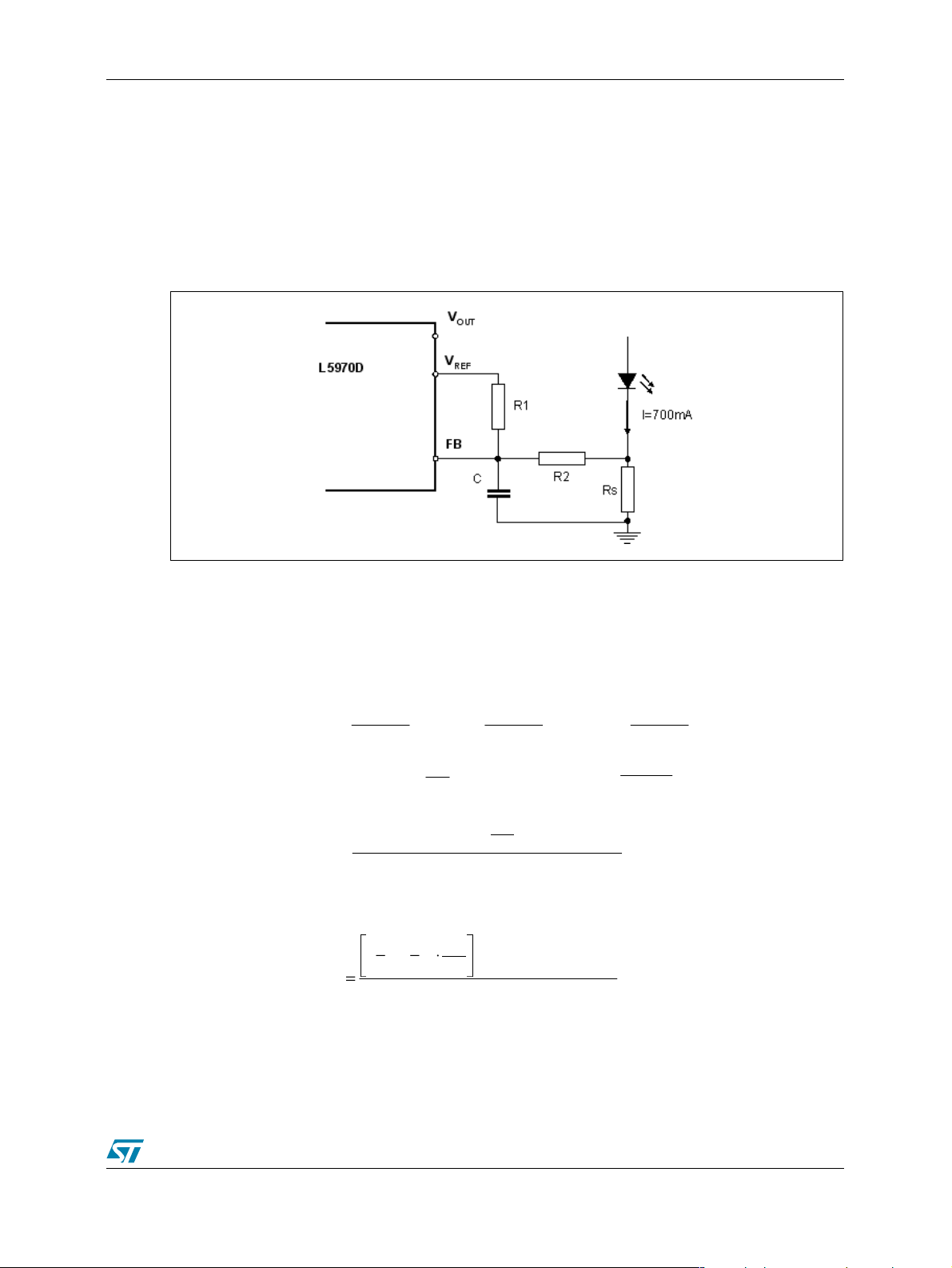
Figure 3. Ripple Current (One 1W LED)
∆Imax = 300mA.
VoVin
−
⋅
To
∆
Figure 3. shows the ripple current measured with one 1W LED (warm white) at the output with
12Vac input. The measured ripple current is 180mA.
11/38
Page 12
4 INDUCTOR SELECTION AN2259
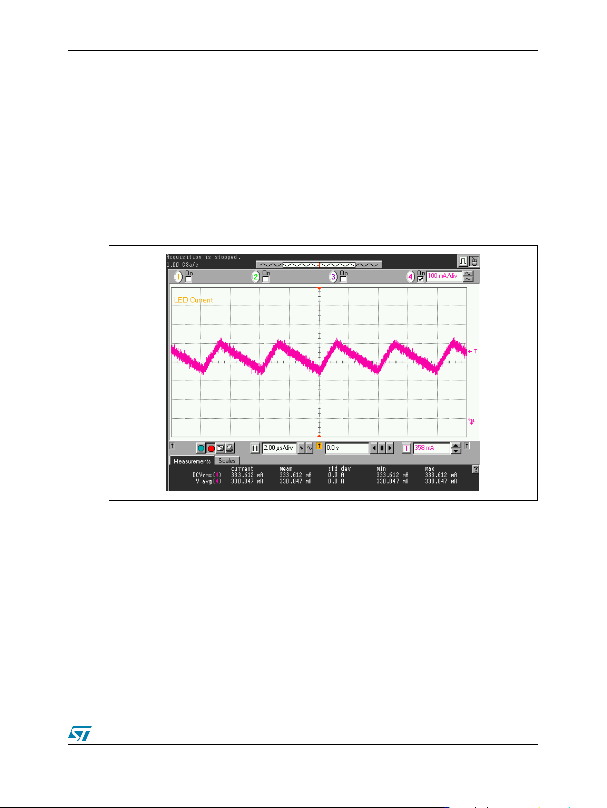
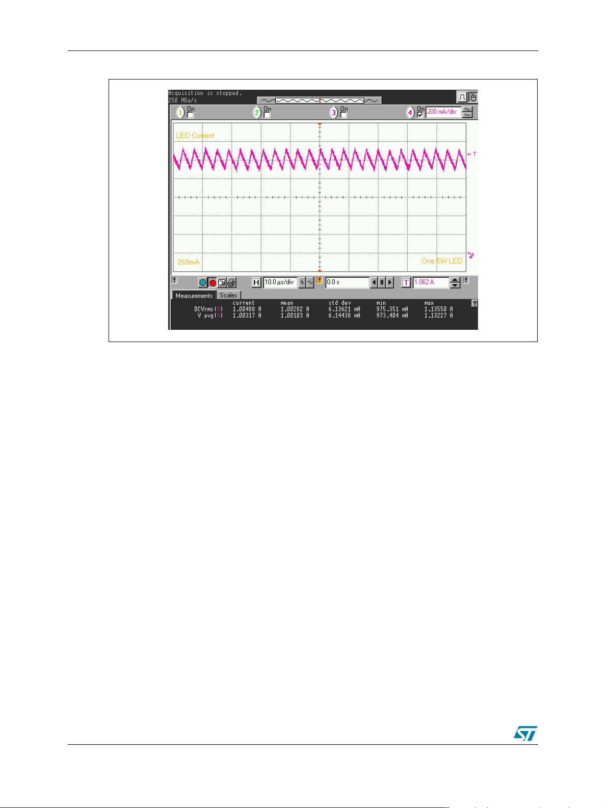
Figure 4. Ripple current (One 5W LED)
Figure 4. shows the ripple current driving one 5W LED at 1.05 A from a 12Vac input. The input
current is 269mA.
12/38
Page 13

AN2259 5 BOARD LAYOUT
5 BOARD LAYOUT
The layout for the evaluation board is shown below in Figure 5. and Figure 6. The area within
the circle in the center of the board illustrates the required area for the final application. The
components outside of the circle are connectors for convenience and the auxiliary devices that
allow the current to be selected on this board without changing the resistor values. Obviously
the final application would use a single resistor for R
Figure 5. Top side of Board (not in scale)
that is optimized for the application.
S
Figure 6. Bottom side of Board (not in scale)
13/38
Page 14

5 BOARD LAYOUT AN2259
Figure 7. Board Sche matic
14/38
Page 15

AN2259 5 BOARD LAYOUT
Table 1. Bill of Matarials
Qty
1 C1 1200uF/35V elect rolytic EEU-FC1V22L Panasonic Radial TH
1 C2 220pF/50V ceramic SMD
1 C3 22nF/50V ceram ic SMD
1 C4 22nF/50V ceram ic SMD
1 C5 4.7nF/50V ceramic SMD
Part
Reference
Part Description Mfg P/N Mfg Geometry Mounting
D2 D4 D5
5
D6 D7
1J1
1 J2 Current Select Ju mper 22-28-8020 Molex TH
1 J3 St ackable Receptacle 535676-5 Tyc o TH
1 J4 Current Select Jumper 22-28-8020 Molex 6 Pin TH
1 L1 Inductor DO3316P-683 Coilcraft SMD
1 Q1 PNP Transistor MMBT3906 STMicroelectronics SOT23 SMD
1 Rs 0.68ohms 1% 1/4W 2010 SMD
1 Rs2 0.68ohms 1% 1/4W 2010 SMD
1 Rs3 0.68ohms 1% 1/4W 2010 SMD
1 R1 2.74kohms 1% 1/8W 0805 SMD
1 R2 1.30kohms 1% 1/8W 0805 SMD
1 R3 4.7kohms 5% 1/8W 0805 SMD
1 R4 240kohms 5% 1/8W 0805 SMD
1 U1 Step-down controller L5973D STMicroelectronics SO8 SMD
Low Drop Power
Schottky R e ctifie r
Phoenix 2 Pin
Connector
STPS2L40U STMicroelectronics SMB SMD
MKDSN1.5/2 Phoenix Contact TH
15/38
Page 16

6 REFERENCE DESIGN VERSIONS AN2259
6 REFERENCE DESIGN VERSIONS
The evaluation board is designed to display the full functionality of L5973D as a LED driver to
drive one to three 1W, 3W as well as 5W LEDs at 12Vac input. The components selected for
the demo board are optimized for 5W LED driver application. Based on this circuit, there are
nine different configurations with different input voltages and output power levels that could be
derived by making minor components changes to the evaluation board. Table 1. shows the
component changes needed in order to obtain each configuration. The final schematics and bill
of materials for each configuration are shown in the subsequent pages. The 6 to 12 Vdc input
configuration was designed for automotive applications that must survive a reverse battery
condition. In this case one of the rectifiers remains on the board to provide protection against
reversing the power supply leads.
Table 2. Components Changes For Different Configuration
LED Driver U1 D4 D5 D6 D7
12Vac
1W LED
12Vac
3W LED
12Vac
5W LED
6-12Vdc
1W LED
6-12Vdc
3W LED
6-12Vdc
5W LED
6-24Vdc
1W LED
6-24Vdc
3W LED
6-24Vdc
5W LED
L5970D STPS1L40A STPS1L40A STPS1L40A STPS1L40A
L5973D STPS2L40U STPS2L40U STPS2L40U STPS2L40U
L5973D STPS2L40U STPS2L40U STPS2L40U STPS2L40U
L5970D Not used Not used STPS1L40A Jumper wire
L5973D Not used Not used STPS2L40U Jumper wire
L5973D Not used Not used STPS2L40U Jumper wire
L5970D Not used Not used Jumper wire Jumper wire
L5973D Not used Not used Jumper wire Jumper wire
L5973D Not used Not used Jumper wire Jumper wire
16/38
Page 17

AN2259 6 REFERENCE DESIGN VERSIONS
Table 2. (Continued)
C1 R2 Rs L1 D2
680uF/35V 1.30k 1% 0.68 47uH STPS1L40A
1200uF/35V 1.33k 1% 0.33 33uH STPS2L40U
1200uF/35V 1.30k 1% 0.24 68uH STPS2L40U
27uF/50V 1.30k 1% 0.68 47uH STPS1L40A
68uF/50V 1.33k 1% 0.33 33uH STPS2L40U
100uF/50V 1.30k 1% 0.24 68uH STPS2L40U
22uF/35V 1.30k 1% 0.68 100uH STPS1L40A
68uF/35V 1.33k 1% 0.33 100uH STPS2L40U
100uF/35V 1.30k 1% 0.24 100uH STPS2L40U
17/38
Page 18

6 REFERENCE DESIGN VERSIONS AN2259
V
V
Figure 8. 12Vac Input 1W LED Driver Schematic
J4
J3
LED+
1
47uH
L1
D2
2.74K
1/8W
R1
1 2
5
6
1
OUT
VREF
LED-
1
STPS1L40A
1 2
R2
FB
GND
7
1.30K
1 2
Rs
0.68
12
1/8W
C4
22nf
R4
240K
1/8W
1 2
1/4W
13
C5
4.7nf
2
Q1
L5970D
U1
VCC
2
8
C1
680uF
D6
D4
J1
in-
INH
3
SYNC
COMP
4
35V
+
STPS 1L40A
1 2
STP S1L40A
1 2
1
R3
4.7K
22nf
220pf
1/8W
D5
STPS 1L40A
D7
STP S1L40A
1
in+
C3
C2
MMBT3906
1 2
1 2
Minimum input voltage for 3 LEDs : 10VAC
Minimum input voltage for 2 LEDs : 7.5VAC
Minimum input voltage for 1 LED : 5VAC
Note:
1 2
J2
18/38
Page 19

AN2259 6 REFERENCE DESIGN VERSIONS
Table 3. 12Vac Input 1W LED Driver Bill of Materials
Qty Reference
Part
Description
Mfg P/N Mfg Geometry Mtg
1C1
1C2
2C3, C4
1C5
D2, D4, D5,
5
1 L1 47uH Inductor DO3308P-473 Coilcraft 9.4mmx12.95mm SMD
1 Q1 PNP Transistor MMBT3906 STMicroelectronics SOT-23 SMD
1 Rs 0.68 Ohm 1% 1206 SMD
1 R1 2.74k 1% 0805 SMD
1 R2 1.30k 1% 0805 SMD
1 R3 4.7k 5% 0805 SMD
1 R4 240k 5% 0805 SMD
1U1
D6, D7
680uF/35V
Electrolytic
220pF/50V
Ceramic
22nF/50V
Ceramic
4.7nF/50V
Ceramic
Schottky Diode
1A/40V
Step-down
controller
EEU-FC1V681 Panasonic Radial TH
SMD
SMD
SMD
STPS1L40A STMicroelectronics SMA SMD
L5970D STMicroelectronics 0SO8 SMD
19/38
Page 20

6 REFERENCE DESIGN VERSIONS AN2259
V
V
Figure 9. 12Vac Input 3W LED Driver Schematic
J4
STPS2L40U
LED-
1
1.33K
1 2
R2
1 2
R4
Rs
0.33
12
1/8W
C4
22nf
240K
1/8W
1 2
1/2W
C5
4.7nf
J3
LED+
1
33uH
L1
D2
2.74K
1/8W
R1
1 2
6
1
OUT
L5973D
U1
VCC
8
J1
5
FB
VREF
GND
7
INH
3
SYNC
COMP
2
4
35V
C1
1200uF
+
D6
STPS2L40U
1 2
D4
STPS2L40U
1 2
1
in-
R3
4.7K
220pf
1/8W
22nf
1 2
D5
STPS2L40U
1 2
D7
STPS2L40U
1 2
1
J2
in+
C3
C2
MMBT3906
2
13
Q1
Note:
Minimum input voltage for 2 LEDs : 8VAC
Minimum input voltage for 1 LED : 5VAC
Minimum input voltage for 3 LEDs : 10.5VAC
20/38
Page 21

AN2259 6 REFERENCE DESIGN VERSIONS
Table 4. 12Vac Input 3W LED Driver Bill of Materials
Qty Reference
Part
Description
Mfg P/N Mfg Geometry Mtg
1C1
1C2
2C3, C4
1C5
D2, D4, D5,
5
1 L1 33uH Inductor DO3308P-333 Coilcraft 9.4mmx12.95mm SMD
1 Q1 PNP Transistor MMBT3906 STMicroelectronics SOT-23 SMD
1 Rs 0.33 Ohm 1%
1 R1 2.74k 1% 0805 SMD
1 R2 1.33k 1% 0805 SMD
1 R3 4.7k 5% 0805 SMD
1 R4 240k 5% 0805 SMD
1U1
D6, D7
1200uF/35V
Electrolytic
220pF/50V
Ceramic
22nF/50V
Ceramic
4.7nF/50V
Ceramic
Schottky Di ode
2A/40V
Step-down
controller
EEU-
FC1V122L
STPS2L40U STMicroelectronics SMB SMD
CRL2010-FW-
R330E
L5973D STMicroelectronics SO8 SMD
Panasonic Radial TH
SMD
SMD
SMD
Bourns 2010 SMD
21/38
Page 22

6 REFERENCE DESIGN VERSIONS AN2259
Figure 10. 12Vac Input 5W LED Driver Schematic
L5973D
U1
J3
LED +
CON1
1
68uH
L1 DO3316P-683
R1
1
6
OUT
VREF
VCC
2
8
LED -
J4
CON1
1
D2
STPS2L40U
2.74K
1/8W
5
FB
SYNC
COMP
4
R2
1 2
GND
7
INH
3
R3
C3
22nF
4.7k
1/8W
Rs
0. 2 4 O h m
1/4W
1 2
1.30K
1/8W
C4
22nf
240k
1/8W
R4
1 2
C5
4.7nf
2
13
Q1
MMBT3906
C2
35V
+
STPS2H10 0U
STPS2H100U
Vin -
220pf
D5
STPS2H10 0U
D7
STPS2H100U
1
Vcc
C1
1200uF
D6
D4
1
J1
CON1
22/38
J2
Vin +
CON1
Note:
Minimum input voltage for 1 LED: 5Vac
Minimum input voltage for 2 LEDs: 8Vac
Minimum input voltage for 3 LEDs: 10.5Vac
Page 23

AN2259 6 REFERENCE DESIGN VERSIONS
Table 5. 12Vac Input 5W LED Driver Bill of Materials
Qty Reference
Part
Description
Mfg P/N Mfg Geometry Mtg
1C1
1C2
2C3, C4
1C5
D2, D4, D5,
5
1 L1 68uH Inductor DO3316P-683 Coilcraft 9.4mmx12.95mm SMD
1 Q1 PNP Transistor MMBT3906 STMicroelectronics SOT-23 SMD
1 Rs 0.24 Ohm 1%
1 R1 2.74k 1% 0805 SMD
1 R2 1.30k 1% 0805 SMD
1 R3 4.7k 5% 0805 SMD
1 R4 240k 5% 0805 SMD
1U1
D6, D7
1200uF/35V
Electrolytic
220pF/50V
Ceramic
22nF/50V
Ceramic
4.7nF/50V
Ceramic
Schottky Di ode
2A/40V
Step-down
controller
EEU-
FC1V122L
STPS2L40U STMicroelectronics SMB SMD
CRL2010-FW-
R240E
L5973D STMicroelectronics SO8 SMD
Panasonic Radial TH
SMD
SMD
SMD
Bourns 2010 SMD
23/38
Page 24

6 REFERENCE DESIGN VERSIONS AN2259
J
V
J
V
Figure 11. 6 to 12Vdc Input 1W LED Driver Schematic
J3
1
47uH
L1
2.74K
R1
1
OUT
L5970D
U1
VCC
8
J4
LED+
D2
1/8W
1 2
6
5
VREF
SYNC
2
4
FB
COMP
LED-
1
STPS1L40A
1 2
GND
INH
C3
1.30K
R2
7
3
R3
4.7K
22nf
1 2
R4
1/8W
1 2
Rs
0.68
12
1/8W
C4
22nf
240K
1/8W
1 2
MMBT390 6
1/4W
2
13
Q1
C5
4.7nf
C2
220pf
50V
C1
27uF
+
D6
STPS1L40A
1 2
1
in+
2
24/38
D7 Jumper
1 2
1
in-
1
Page 25

AN2259 6 REFERENCE DESIGN VERSIONS
Table 6. 6 to 12Vdc Input 1W LED Driver Bill of Materials
Qty Reference
Part
Description
Mfg P/N Mfg Geometry Mtg
1C1
1C2
2C3, C4
1C5
2D2, D6
1D7
1 L1 47uH Inductor DO3308P-473 Coilcraft 9.4mmx12.95mm SMD
1 Q1 PNP Transistor MMBT3906 STMicroelectronics SOT-23 SMD
1 Rs 0.68 Ohm 1% 1206 SMD
1 R1 2.74k 1% 0805 SMD
1 R2 1.30k 5% 0805 SMD
1 R3 4.7k 5% 0805 SMD
1 R4 240k 5% 0805 SMD
1U1
27uF/50V
Electrolytic
220pF/50V
Ceramic
22nF/50V
Ceramic
4.7nF/50V
Ceramic
Schottky Di ode
1A/40V
Jumper at D7
position
Step-down
controller
EEU-
FC1H270
STPS1L40A STMicroelectronics SMA SMD
L5970D STMicroelectronics SO8 SMD
Panasonic Radial TH
SMD
SMD
SMD
SMD
25/38
Page 26

6 REFERENCE DESIGN VERSIONS AN2259
J
V
Figure 12. 6 to 12Vdc Input 3W LED Driver Schematic
J4
STPS2L40U
FB
LED-
1
1 2
GND
1.33K
R2
7
1 2
R4
Rs
0.33
12
1/8W
C4
22nf
240K
1/8W
1 2
1/2W
2
13
Q1
C5
4.7nf
J3
LED+
1
33uH
L1
D2
2.74K
1/8W
R1
1 2
6
1
OUT
5
VREF
L5973D
U1
D6
2
INH
3
SYNC
VCC
8
C6
1 2
1
COMP
2
4
50V
68uF
+
STPS2L40U
in+
C3
C2
220pf
22nf
R3
4.7K
1/8W
D7 Jumper
J1
MMBT3906
1 2
1 2
1
Vin-
26/38
Page 27

AN2259 6 REFERENCE DESIGN VERSIONS
Table 7. 6 to 12Vdc Input 3W LED Driver Bill of Materials
Qty Reference
Part
Description
Mfg P/N Mfg Geometry Mtg
1C1
1C2
2C3, C4
1C5
2D2, D6
1D7
1 L1 33uH Inductor DO3308P-333 Coilcraft 9.4mmx12.95mm SMD
1 Q1 PNP Transistor MMBT3906 STMicroelectronics SOT-23 SMD
1 Rs 0.33 Ohm 1%
1 R1 2.74k 1% 0805 SMD
1 R2 1.33k 1% 0805 SMD
1 R3 4.7k 5% 0805 SMD
1 R4 240k 5% 0805 SMD
68uF/50V
Electrolytic
220pF/50V
Ceramic
22nF/50V
Ceramic
4.7nF/50V
Ceramic
Schottky Di ode
2A/40V
Jumper at D7
position
EEU-
FC1H680
STPS2L40U STMicroelectronics SMB SMD
CRL2010-FW-
R330E
Panasonic Radial D8mm TH
805 SMD
805 SMD
805 SMD
SMD
Bourns 2010 SMD
1U1
Step-down
controller
L5973D STMicroelectronics SO8 SMD
27/38
Page 28

6 REFERENCE DESIGN VERSIONS AN2259
Figure 13. 6 to 12Vdc Input 5W LED Driver Schematic
LED -
LED +
J4
1
Rs
0.24Ohm
1/4W
1 2
J3
1
L5973D
U1
L1 DO3316P-683
68uH
D2
STPS2L40U
R1
2.74K
1/8W
6
VREF
C1
5
FB
SYNC
COMP
2
4
50V
100uF
+
1
OUT
VCC
8
Vcc
Vcc
1 2
GND
INH
7
3
C3
22nF
C2
R2
R3
220pF
4.7k
1/8W
1.30K
1/8W
C4
R4
240k
22nF
1/8W
1 2
2
13
Q1
MMBT3906
C5
4.7nF
D6
STPS2H100U
1
J2
CON1
Vin +
28/38
D7 Jumper
J1
1 2
1
CON1
Vin -
Page 29

AN2259 6 REFERENCE DESIGN VERSIONS
Table 8. 6 to 12Vdc Input 5W LED Driver Bill of Materials
Qty Reference
Part
Description
Mfg P/N Mfg Geometry Mtg
1C1
1C2
2C3, C4
1C5
2D2, D6
1D7
1 L1 68uH Inductor DO3316P-683 Coilcraft 9.4mmx12.95mm SMD
1 Q1 PNP Transistor MMBT3906 STMicroelectronics SOT-23 SMD
1 Rs 0.24 Ohm 1%
1 R1 2.74k 1% 0805 SMD
1 R2 1.30k 1% 0805 SMD
1 R3 4.7k 5% 0805 SMD
1 R4 240k 5% 0805 SMD
100uF/50V
Electrolytic
220pF/50V
Ceramic
22nF/50V
Ceramic
4.7nF/50V
Ceramic
Schottky Di ode
2A/40V
Jumper at D7
position
EEU-
FC1H101
STPS2L40U STMicroelectronics SMB SMD
CRL2010-FW-
R240E
Panasonic Radial D8mm TH
805 SMD
805 SMD
805 SMD
SMD
Bourns 2010 SMD
1U1
Step-down
controller
L5973D STMicroelectronics SO8 SMD
29/38
Page 30

6 REFERENCE DESIGN VERSIONS AN2259
J
V
J
V
Figure 14. 6 to 24Vdc Input 1W LED Driver Schematic
J3
L5970D
U1
J4
LED+
1
100uH
L1
D2
2.74K
1/8W
R1
1 2
1
OUT
VCC
8
5
6
FB
VREF
SYNC
COMP
2
4
1
STPS1L40A
1 2
GND
INH
C3
7
3
22nf
LED-
Rs
0.68
1/4W
12
1.30K
1/8W
R2
C4
22nf
1 2
R4
240K
R3
1/8W
1 2
MMBT3906
4.7K
1/8W
1 2
2
13
Q1
C5
4.7nf
C2
220pf
35V
C1
22uF
+
D6 J um per1
1 2
1
in+
2
24V
30/38
D7 J um per
1 2
1
in-
1
Page 31

AN2259 6 REFERENCE DESIGN VERSIONS
Table 9. 6 to 24Vdc Input 1W LED Driver Bill of Materials
Qty Reference
Part
Description
Mfg P/N Mfg Geomet ry Mtg
1C1
1C2
2C3, C4
1C5
1D2
1D7
1D6
1 L1 100uH Inductor DO3308P-104 Coilcraft
1 Q1 PNP Transistor MMBT3906 STMicroelectronics SOT-23 SMD
1 Rs 0. 68 Ohm 1% 1206 SMD
1 R1 2.74k 1% 0805 SMD
1 R2 1.30k 1% 0805 SMD
22uF/35V
Electrolytic
220pF/50V
Ceramic
22nF/50V
Ceramic
4.7nF/50V
Ceramic
Schottky Di ode
1A/40V
Jumper at D7
position
Jumper at D6
position
EEU-
FC1H220
STPS1L40A STMicroelectronics SMA SM D
Panasonic Radial TH
SMD
SMD
SMD
SMD
SMD
9.4mm x
12.95mm
SMD
1 R3 4.7k 5% 0805 SMD
1 R4 240k 5% 0805 SMD
1U1
Step-down
controller
L5970D STMicroelectronics SO8 SMD
31/38
Page 32

6 REFERENCE DESIGN VERSIONS AN2259
J
V
Figure 15. 6 to 24Vdc Input 3W LED Driver Schematic
L5973D
U1
J3
1
100uH
L1
2.74K
R1
1
OUT
VCC
8
J4
LED+
D2
1/8W
1 2
6
5
FB
VREF
SYNC
COMP
2
4
LED-
1
STPS2L40U
1 2
GND
INH
C3
1.33K
R2
7
3
R3
4.7K
22nf
1 2
R4
1/8W
1 2
Rs
0.33
12
1/8W
C4
22nf
240K
1/8W
1 2
MMBT3906
1/2W
2
13
Q1
C5
4.7nf
C2
220pf
35V
C1
68uF
+
D6 J umper
1 2
1
J2
Vin+
24V
32/38
D7 Jumper
1 2
1
in-
1
Page 33

AN2259 6 REFERENCE DESIGN VERSIONS
Table 10. 6 to 24Vdc Input 3W LED Driver Bill of Materials
Qty Reference
Part
Description
Mfg P/N Mfg Geomet ry Mtg
1C1
1C2
2C3, C4
1C5
1D2
1D6
1D7
1 L1 100uH Inductor DO3316P-104 Coilcraft
1 Q1 PNP Transistor MMBT3906 STMicroelectronics SOT-23 SMD
1 Rs 0.33 Ohm 1%
1 R1 2.74k 1% 0805 SMD
1 R2 1.33k 1% 0805 SMD
1 R3 4.7k 5% 0805 SMD
68uF/35V
Electrolytic
220pF/50V
Ceramic
22nF/50V
Ceramic
4.7nF/50V
Ceramic
Schottky Di ode
2A/40V
Jumper at D6
position
Jumper at D7
position
EEU-
FC1V680
STPS2L40U STMicroelectronics SMB SMD
CRL2010-FW-
R330E
Panasonic Radial TH
SMD
SMD
SMD
SMD
SMD
9.4mm x
12.95mm
Bourns 2010 SMD
SMD
1 R4 240k 5% 0805 SMD
1U1
Step-down
controller
L5973D STMicroelectronics SO8 SMD
33/38
Page 34

6 REFERENCE DESIGN VERSIONS AN2259
0.24o
J4
E
D
Figure 16. 6 to 24Vdc Input 5W LED Driver Schematic
L5973D
L1 DO3316P-104
U1
J3
LE
1
L
1
Rs
1/4W
1 2
100uH
R1
D2
2.74K
STPS2L40U
1/8W
R2
1.30K
1/8W
1 2
R4
C4
240k
22nF
1/8W
1 2
C5
4.7nF
1
OU T
VCC
8
5
6
FB
VREF
GND
7
INH
3
SYNC
COMP
2
4
C3
R3
4.7k
1/8W
22nF
2
13
Q1
MMBT3906
VccVcc
Vcc
35V
C1
100uF
+
D6 Jumper
1 2
1
J2
CON1
Vin +
34/38
C2
220pF
D7 Jumper
J1
1 2
1
CON1
Vin -
Page 35

AN2259 6 REFERENCE DESIGN VERSIONS
Table 11. 6 to 24Vdc Input 5W LED Driver Bill of Materials
Qty Reference
Part
Description
Mfg P/N Mfg Geomet ry Mtg
1C1
1C2
2C3, C4
1C5
1D2
1D6
1D7
1 L1 100uH Inductor DO3316P-104 Coilcraft
1 Q1 PNP Transistor MMBT3906 STMicroelectronics SOT-23 SMD
1 Rs 0.24 Ohm 1%
1 R1 2.74k 1% 0805 SMD
1 R2 1.30k 1% 0805 SMD
1 R3 4.7k 5% 0805 SMD
100uF/35V
Electrolytic
220pF/50V
Ceramic
22nF/50V
Ceramic
4.7nF/50V
Ceramic
Schottky Di ode
2A/40V
Jumper at D6
position
Jumper at D7
position
EEU-
FC1V101
STPS2L40U STMicroelectronics SMB SMD
CRL2010-FW-
R240E
Panasonic Radial TH
SMD
SMD
SMD
SMD
SMD
9.4mm x
12.95mm
Bourns 2010 SMD
SMD
1 R4 240k 5% 0805 SMD
1U1
Step-down
controller
L5973D STMicroelectronics SO8 SMD
35/38
Page 36

7 REVISION HISTORY AN2259
7 REVISION HISTORY
Date Revision Changes
04-Nov-2005 1.0 First edition
36/38
Page 37

AN2259 7 REVISION HISTORY
37/38
Page 38

7 REVISION HISTORY AN2259
I
s
o
d
b
ct
t
ot
a
nformation furnished is believed to be accurate and reliable. However, STMicroelectronics assumes no responsibility for the consequence
f use of such information nor for any infringement of patents or other rights of third parties which may result from its use. No license is grante
y implic ation or otherwise under any patent or pat ent rights of STMicroelectronics. Specifications mentioned in thi s publicatio n are sub je
o change without notice. This publication supersedes and replaces all information previously supplied. STMicroelectronics products are n
uthoriz ed for use as critical compo nents in life support devic es or systems without express written approval of STMicroel ectronics.
The ST logo is a registered t rademark of ST M i croelectr oni cs.
All other nam es are the pro perty of their respectiv e owners
Austra l i a - Be l gi um - Brazil - Canada - China - Czech Rep ubl ic - Finlan d - F rance - Germ any - Hong Kon g - India - Israel - Italy - Japan -
Malaysi a - M al ta - Morocco - Singapore - Spain - Swe den - Switze rl and - United Kingdom - United States of America
© 2005 STMi croelectronics - All rights reserved
STMicroelectron ics group of com panies
www.st.com
38/38
 Loading...