

Page 1

AN2244
Application note
EEPROM emulation with ST10F27x embedded Flash
using the ST10F27x Flash library
Introduction
The ST10F27x MCUs provide 0.18µm embedded true Flash technology.
This Flash technology has been designed to store software program instructions and is not
adapted to dynamic data storage because it can only be erased by sector.
Typically, when the code is programmed, some portions of the Flash remain free. This
unused space can be used as virtual EEPROM, thus avoiding the additional cost and
complexity incurred by using an external serial EEPROM.
This application note shows a method of performing EEPROM emulation. It provides
software routines to overcome the Flash limitations in terms of read/write access and
number of cycles.
This document is divided into the following sections:
■ Overview of ST10F27x Embedded Flash
■ The ST10F27x Flash library provided by STMicroelectronics
■ Application example: EEPROM Emulation. This application example helps the user to
become familiar with the ST10F27x Flash library, given that it uses the main important
Flash library functions of programming, erasing and verifying.
The application source files are provided within an associated downloadable package. This
file must be unpacked into a directory before use.
The EEPROM emulation driver was compiled using the two tool chains, Tasking and Keil,
and it can be ported easily to any other ST10 tool chain.
For more information, please refer to the ST10F27x related documentation.
January 2007 Rev 1 1/17
www.st.com
Page 2

AN2244
Contents
1 ST10F27x embedded Flash overview . . . . . . . . . . . . . . . . . . . . . . . . . . . 3
2 The ST10F27x Flash library . . . . . . . . . . . . . . . . . . . . . . . . . . . . . . . . . . . 4
3 Application example: EEPROM emulation using ST10F27x Flash library
5
3.1 Purpose . . . . . . . . . . . . . . . . . . . . . . . . . . . . . . . . . . . . . . . . . . . . . . . . . . . 5
3.2 Principle . . . . . . . . . . . . . . . . . . . . . . . . . . . . . . . . . . . . . . . . . . . . . . . . . . . 5
3.3 ST10F27x embedded Flash vs. EEPROM: program/erase cycles . . . . . . . 7
3.4 EEPROM software description . . . . . . . . . . . . . . . . . . . . . . . . . . . . . . . . . . 8
3.4.1 Header field . . . . . . . . . . . . . . . . . . . . . . . . . . . . . . . . . . . . . . . . . . . . . . . 8
3.4.2 Variables array . . . . . . . . . . . . . . . . . . . . . . . . . . . . . . . . . . . . . . . . . . . . . 8
3.4.3 Project routines . . . . . . . . . . . . . . . . . . . . . . . . . . . . . . . . . . . . . . . . . . . . 9
3.4.4 Using EEPROM routines in a main program . . . . . . . . . . . . . . . . . . . . 13
3.4.5 Program execution . . . . . . . . . . . . . . . . . . . . . . . . . . . . . . . . . . . . . . . . . 13
4 Software limitations . . . . . . . . . . . . . . . . . . . . . . . . . . . . . . . . . . . . . . . . 14
5 References . . . . . . . . . . . . . . . . . . . . . . . . . . . . . . . . . . . . . . . . . . . . . . . . 15
6 Revision history . . . . . . . . . . . . . . . . . . . . . . . . . . . . . . . . . . . . . . . . . . . 16
2/17
Page 3
AN2244 1 ST10F27x embedded Flash overview
1 ST10F27x embedded Flash overview
The ST10F27x provides an on-chip high-speed single voltage Flash memory.
The write operations of the ST10F27x Flash banks are managed by an embedded Flash
Program/Erase Controller.
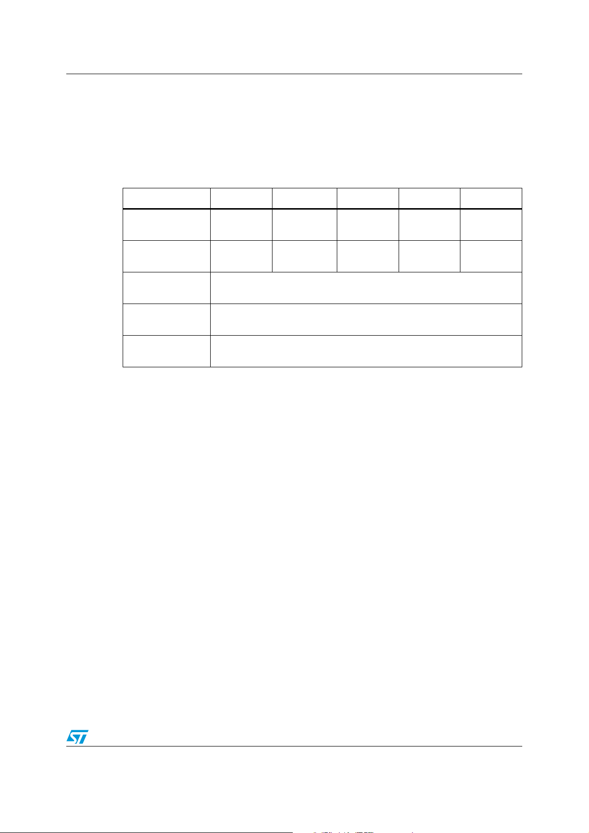
The following table summarizes the main ST10F27x Embedded Flash characteristics:
ST10F271 ST10F272 ST10F273 ST10F275 ST10F276
Flash Size
(KBytes)
Flash Organization
Banks / Sectors
Programming
voltage
Programming
method
Program/Erase
cycles
128 256 512 832 832
1 /6 1 / 8 2 / 12 4 /17 4 /17
5 Volts
Write/Erase Controller
100 Kcycles, 20 years data retention
Depending on the ST10 derivative, the Flash memory will be composed either of 1 module
(IFLASH) or of 2 modules (IFLASH and XFLASH). Each module is divided into several
banks, themselves sub-divided into sectors.
The ST10F276 and ST10F275 embedded Flash is composed of two modules.
The ST10F271, ST10F272 and ST10F273 embedded Flash is composed of one module.
On the IFLASH, the internal data bus is 32 bits wide (I-BUS).
The XFLASH module is mapped on the XBUS and the data bus is 16 bits wide (X-BUS).
The smallest erasable part of Flash is a sector.
3/17
Page 4

2 The ST10F27x Flash library AN2244
2 The ST10F27x Flash library
The Flash programming library is a set of optimized C routines and contains everything
needed to program the embedded Flash of ST10 devices in 0.18µ technology, i.e the
ST10F27x family devices.
The Flash library contains the following source files:
● flash.c, containing the functions’ code
● flash.h, containing the functions’ prototypes
● F27x_flash.h, containing the definitions of the Flash registers and sectors’ size for the
ST10F27x devices Flash
To use the functions provided by the Flash library, these files must be added to the project.
The CPU frequency must be set in F27x_flash.h library file:
#define Fcpu_MHz ((unsigned int) 40)
In order to be able to use the ST10F27x Flash library, the MCU(ST10F27x derivative) and
the toolchain (Tasking or Keil) must be defined and start up configurations must be properly
set up.
For more details about the ST10F27x Flash library and how to use it, please refer to the
"Flash programming for ST10 devices in 0.18um technology" application note.
4/17
Page 5

AN2244 3 Application example: EEPROM emulation using ST10F27x Flash library
3 Application example: EEPROM emulation using
ST10F27x Flash library
3.1 Purpose
The purpose of this example is to show how a portion of the ST10F27x embedded Flash
can be used to replace a serial EEPROM to store and update non volatile data in order to
save the cost of an external EEPROM.
3.2 Principle
The implementation shown in this application note requires that a minimum of two Flash
sectors of identical size are allocated to non volatile data storage. In this example, the sector
1 and sector 2, 8 kbytes each, of the Flash bank 0 are used.
Those sectors are write accessed in 32-bit.
A header field occupying the first 32-bit word of each sector represents the sector’s status.
In order to use Flash to store several non volatile variables, we need to divide the two
sectors identically into several parts, one per variable.
For each variable, the size of the memory space is allocated according to its update
frequency. The first 32-bit value of each variable is stored at the base address of its
allocated memory space. When updated, the new value is stored at the next available
address: base address + 4, base address + 8 and so on until no room remains from its
allocated memory.
Example:
In the sector 1, we assume 3 variables: A, B and C will be stored and updated.
The first variable A value is stored at t
0
The second variable B value is stored at t
The third variable C value is stored at t
2
and variable A(t) is updated every
and variable B(t) is updated every
1
and variable C(t) is updated every
t
A
t
B
t
C
In a typical application, the majority of non volatile data is updated infrequently and a few is
updated more frequently.
Let’s consider t
< tB< tC , this means that A is updated more than B which is updated more
A
than C so more memory space should be allocated to A and B than C.
In this application, sector 1 is divided as follows:
● 0x2000-0x2FFF memory space will be allocated to variable A
● 0x3000-0x3FEB memory space will be allocated to variable B
● 0x3FEC-0x3FFF memory space will be allocated to variable C
5/17
Page 6
3 Application example: EEPROM emulation using ST10F27x Flash library AN2244
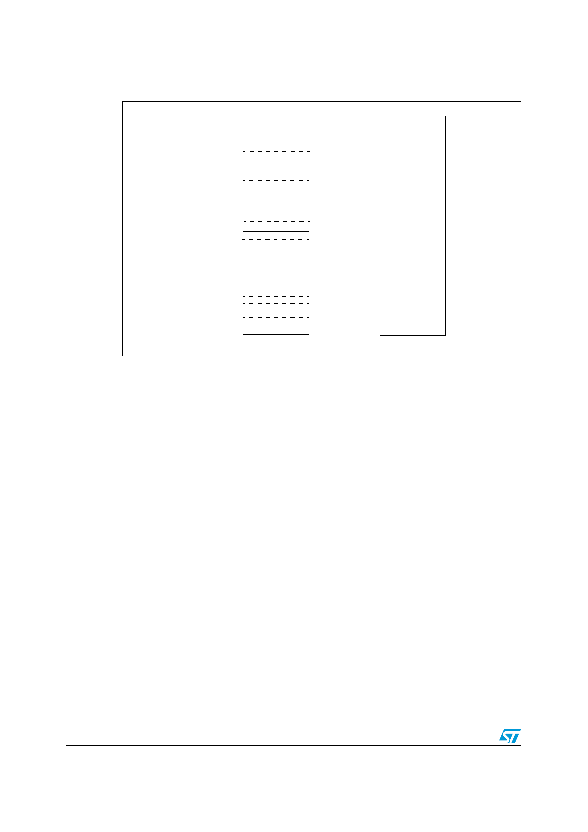
Figure 1. Variable updates in sector 1
0x3FFF
0x3FF0
0x3FEC
0x3010
0x300C
0x3008
0x3004
0x3000
0x2014
0x2010
0x200C
0x2008
0x2004
0x2000
C(t
+ tC)
2
C( t2 )
B(t1 + m * tB)
.......
.......
B(t
+ 3 * tB)
1
B(t
+ 2* tB)
1
B(t
+ tB)
1
B(
t1 )
A(t
+ n * tA)
0
.......
.......
.......
.......
.......
.......
.......
A(t
+ 3 * tA)
0
+ 2 * tA)
A(t
0
A(t
+ tA)
0
A( t0 )
sector 1 header
sector 1
0x5FFF
0x5FEC
0x5000
0x4000
sector 2 header
sector 2 erased
In sector 1, variables are stored until there is insufficient memory space to allocate to one of
these variables (case of variable A in the example).
Assume that the variable A should be updated at the time t
+ (n+1) * t
0
with A(t
A
+ (n+1) * t
0
).
A
Addresses from 0x2004 to 0x2FFC are all full, the next value is then stored in the base
address of the space allocated to the variable A in the sector 2.
The latest stored value of every other variable (B and C) is transferred from its last location
in sector 1 to the base address of its allocated space in sector 2.
This is illustrated in the Figure 2.
6/17
Page 7

AN2244 3 Application example: EEPROM emulation using ST10F27x Flash library
Figure 2. Variable transfer when sector 1 is full
0x3FFF
0x3FF0
0x3FEC
0x3010
0x300C
0x3008
0x3004
store
+ (n + 1) * tx)
x(t
0
but there isn’t enough
memory space allocated
for variable A
0x3000
0x2014
0x2010
0x200C
0x2008
0x2004
0x2000
C(t
+ tC)
2
)
C( t
2
B(t1 + m * tB)
.......
.......
+ 3 * tB)
B(t
1
+ 2 * tB)
B(t
1
+ tB)
B(t
1
B(
t1 )
A(t
+ n * tA)
0
.......
.......
.......
.......
.......
.......
+ 3 * tA)
A(t
0
+ 2 * tA)
A(t
0
+ tA)
A(t
0
A( t0 )
sector 1 header
sector 1
0x5FFF
0x5FEC
0x5000
0x4000
C(t2 + tC)
B(t1 + m * tB)
A(t
+ (n + 1 ) * tA)
0
sector 2 header
sector 2
After the transfer of all variables is complete, sector 1 is erased.
Variables are then stored and updated in sector 2 in the same way described for sector 1.
When there is not enough memory space left for one of these variables in sector 2, we
switch back to sector 1 (now empty) in the same way and so on.
3.3 ST10F27x embedded Flash vs. EEPROM: program/erase cycles
One program/erase cycle is composed of one or several write accesses and one sector
erase operation.
When EEPROM technology is used, each byte can be programmed and erased a finite
number of times, typically in the range of 10,000 to 100,000.
However, when Flash is used, the minimum erase size is a sector and the number of
Program/Erase cycles applied to a sector is the number of erase cycles. The ST10F27x
electrical characteristics guarantee 100,000 Program/Erase cycles per sector.
In our example, two 8 kbyte sectors are used and programming is done with 32-bit words.
If we consider that the memory space allocated to variable A is always filled up before
spaces allocated to variables B and C, the expected number of erase cycles is driven by
variable A. As 4092 bytes are allocated to A, it can be updated 1023 times before switching
and erasing sectors. Two sectors are used that can be erased 100,000 times so the total
number of cycles we can expect for A is: 1023 x 2 x 100,000 = 204,600,000 cycles.
The number of cycles (common to all variables) is the number of cycles taken for the 1st
variable to fill all of its allocated memory space (variable A in our example).
7/17
Page 8

3 Application example: EEPROM emulation using ST10F27x Flash library AN2244
3.4 EEPROM software description
This section describes the software implemented for EEPROM emulation using the
ST10F27x Flash library provided by STMicroelectronics.
This example uses the 3 variables A, B and C already defined.
The project contains 3 source files in addition to the three library source files:
● eeprom.c: containing C code for the following project routines
EepromFormat( )
WriteVariable( )
ReadVariable( )
FindValidSector( )
WriteVerifyVariableFull( )
EepromSectorTransfer( )
FlashRead( )
● eeprom.h: containing the routines’ prototypes and some declarations.
● main.c: This application program is an example that uses the routines described in
eeprom.c in order to write and read from the eeprom.
3.4.1 Header field
The header field occupies each sector base address and gives the sector’s status
information. Each sector has four possible states:
● ERASED: This sector is empty.
● RECEIVE_DATA: This sector is receiving data from the full one.
● VALID_SECTOR: This sector contains valid data and this state will not change until
valid data are completely transferred to the erased sector.
● TRANSFER_COMPLETE: Transfer of data to the other sector is finished and this
sector is no longer in use. The system can then erase this sector to prepare it for future
data.
The Figure 3 shows how to switch from one state to another for both sectors.
3.4.2 Variables array
Every variable is defined by its start address in its allocated memory space.
An array of variables is declared and located in the user application as described in
Section 3.4.4
Its size must be defined in the eeprom.h file.
8/17
Page 9

AN2244 3 Application example: EEPROM emulation using ST10F27x Flash library
Figure 3. Header status switching between sectors 1 and 2
3.4.3 Project routines
EepromFormat( ) routine
This function erases sector 1 and sector 2, and writes a VALID_SECTOR header to sector
1.
Valid1 Erased2
Sector 1 Full
Valid1 Receive2
Transfer 1->2 complete
Transfer_
Complete1
Erased1 Valid2
Receive1 Valid2
Valid1 Transfer_
Valid2
Erase1
Sector 2 Full
Transfer 1->0 complete
Complete2
Erase2
Write data1
Copy data1->2
Write data2
Copy data2->1
WriteVariable( ) routine
This function is called by the user application. It uses WriteVerifyVariableFull( ) and
EepromSectorTransfer( ) routines described later.
See below the procedure of updating a variable entry in the eeprom.
Figure 4. WriteVariable flowchart
WriteVariable
status = WriteVerifyVariableFull( )
if status = 0
return 0 on success
return 0 on success
Note: 1 For more informations about Flash error codes, please refer to the "Flash programming for
ST10 devices in 0.18µ technology" application note.
if status=0x80 (Variable full)
status = EepromSectorTransfer( )
return Flash error code
on failure.(1)
9/17
Page 10

3 Application example: EEPROM emulation using ST10F27x Flash library AN2244
ReadVariable( ) routine
This function reads variable data. Only last update is read. The function enters in a loop in
which it reads the variable entries until the last one is found. Finally, the data is returned.
See below for the procedure of reading the last variable entry in the eeprom.
Figure 5. ReadVariable flowchart
ReadVariable
Find Valid sector
address = address +4
return VARIABLE_EMPTY
output = FlashRead(address - 4)
return output
address = base address of the variable in the valid sector
No
Ye s
No
Read_data = FlashRead(address)
Read_Data=0xFFFFFFFF ?
Ye s
FlashRead(address+4) =0x00000000?
No
FlashRead(address+4) =0xFFFFFFFF?
address = variable start address ?
FlashRead(address-8)=0xFFFFFFFF?
FlashRead(address-4)=0x00000000?
Ye s
No
&&
Ye s
address = address + 8
Ye s
WriteVerifyVariableFull( ) routine
If a write should occur, the write process must either update a variable, or create the first
instance of a variable. The routine has as parameters:
● variable index (0 for A, 1 for B or 2 for C)
● all variables Array
● 32-bit data to be written
If the data to be written is equal to 0xFFFFFFFF, we look for the last data equal to
0xFFFFFFFF and we write 0x00000000 in next location to indicate that 0xFFFFFFFF is a
data and not a blank location.
10/17
output = 0xFFFFFFFF
return output
Page 11

AN2244 3 Application example: EEPROM emulation using ST10F27x Flash library
If the data to be written is different from 0xFFFFFFFF, we look for the last data equal to
0xFFFFFFFh (the following location should not contain 0x00000000) and the data is written
at this location.
The following diagram summarizes the write operation and treats the cases where written
data is equal to or different from 0xFFFFFFFF. This routine will return 0 on success,
VARIABLE_FULL if there isn’t enough memory for a variable update, or a Flash error code
indicating an operation failure (erase or program).
Figure 6. WriteVerifyVariableFull routine flowchart
Write_request
Find Valid sector
Calculate the base address of the
variable in the valid sector address
status = FlashVerifyWord (address,0xFFFFFFFF)
status1 = FlashVerifyWord (address+4,0xFFFFFFFF)
status2 = FlashVerifyWord (address+4,0x00000000)
status=0?
Ye s
&&
status1=0?
No
Ye s
FlashProgramWord(address+4,0)
return 0
Data=
0xFFFFFFFF?
No
address=address+8
FlashProgramWord(address, Data)
return 0
Ye s
status=0?
&&
status2=0?
address=address+4
No
EepromSectorTransfer( ) routine
This routine transfers the most recent data (Last variable updates) plus the new one from a
full sector to an empty one. At the beginning, it determines the active sector which is the
sector that we want to transfer from. The new sector header field is defined and written (new
sector status is RECEIVE_DATA given that it is in the process of receiving data). When, the
data transfer is complete, the new sector header is marked VALID_SECTOR and the old
one TRANSFER_COMPLETE. At the end, the old sector is erased.
The transfer process is shown in the following figure:
11/17
Page 12

3 Application example: EEPROM emulation using ST10F27x Flash library AN2244
Figure 7. EepromSectorTransfer flowchart
Write new sector header
RECEIVE DATA
Transfer Data to new sector
( including the new one)
Mark old sector TRANSFER
COMPLETE
sector
VALID
Mark new sector
Erase old sector
FindValidSector( ) routine
This function reads both sector headers and returns the sector number which contains valid
data. It has as parameter a byte indicating that we are looking for a valid sector for write or
read operation( READ_FROM_VALID_SECTOR or WRITE_IN_VALID_SECTOR).
The following diagram describes this routine principle.
Figure 8. Find_Valid_sector flowchart
Find_Valid_Sector(operation)
Switch operation
Write
sector 1
No
status
=valid ?
Yes
sector 2
No
status
=valid?
Yes
sector 2
status
=receive data?
Yes
No
Read
sector 1
status
=valid ?
Yes
Return sector 1
No
sector 2
No
status
=valid?
Yes
Return No_Valid_Sector
sector 1
status
= receive data?
Yes
Return sector 1
Return sector 2
No
Return sector 2
FlashRead( ) routine
This routine allows 32-bit data to be read from a given Flash address.
12/17
Return sector 1
Return sector 2
Return No_Valid_Sector
Page 13

AN2244 3 Application example: EEPROM emulation using ST10F27x Flash library
Program/Erase functions
In this application, the following functions provided by the Flash library are used:
● FlashVerifyWord( )
● FlashProgramWord( )
● FlashSectorErase( )
● FlashWait( )
3.4.4 Using EEPROM routines in a main program
The number of variables needed must be defined in the eeprom.h file. For example,
#define max_varia 0x3
#define A 0x2004
#define B 0x3000
#define C 0x3FEC
//#define D ...
etc...
The application must declare the variables array:
u32 Tab[max_varia] =
{A,
B,
C
//D,
etc...
};
To write in the eeprom, use the WriteVariable( ) routine which returns "0" on success and
the error code upon failure. Reading from the eeprom is performed by the ReadVariable( )
routine.
3.4.5 Program execution
The internal Flash of some ST10F27x derivatives (ST10F276, ST10F275 and ST10F273)
offers the ability to update one bank while code is executed from another bank. Therefore
there is no need to transfer Flash operations (Program/Erase) to RAM. In this case, the
emulation driver can be downloaded into a bank other than bank0.
The internal Flash of the remaining ST10F27x dervatives (ST10F271 and ST10F272)
contains just one bank. Therefore, the Flash operations (Program/Erase) must be copied
into and executed from RAM.
13/17
Page 14

4 Software limitations AN2244
4 Software limitations
Data or sector headers corruption is possible in the case of power loss during variables
update or sectors erase or transfer.
To detect this corruption and recover it, a routine EEPROM_INIT( ) must be written and
called immediately after power on.
This routine is not implemented in this version of this application note. This section is limited
to the description of its principle.
The routine must use the sector status to check integrity and to perform repair if necessary.
After power loss, the EEPROM_INIT( ) routine is used to check sector header status. There
are 16 possible status combinations, half of which are invalid. The following table shows the
actions that should be taken based on the sectors states upon power up.
Table 1. Status combinations and actions to be taken
Sector 1
Sector 2
ERASED
RECEIVE_DATA
VALI D_DATA
TRANSFER
COMPLETE
ERASED RECEIVE_DATA VALID_DATA
Invalid state: erase
both sectors and
format sector 1
Invalid state: erase
both sectors and
format sector 1
Use sector 2 as
valid sector and
erase sector 1
Invalid state: erase
both sectors and
format sector 1
Invalid state: erase
both sectors and
format sector 1
Invalid state: erase
both sectors and
format sector 1
Use sector 2 as
valid sector and
erase sector 1 and
transfer data from 2
to 1
Use sector 1 as
valid sector and
erase
sector 2
Use sector 1 as
valid sector and
erase
sector 2
Use sector 1 as
valid sector and
erase sector 2 and
transfer data from 1
to 2
Invalid state:
erase both sectors
and format sector 1
Use sector 1 as
valid sector and
erase
sector 2
TRANSFER
COMPLETE
Invalid state:
erase both sectors
and format sector 1
Use sector 2 as
valid sector and
erase sector 1
Use sector 2 as
valid sector and
erase sector 1
Invalid state:
erase both sectors
and format sector 1
14/17
Page 15

AN2244 5 References
5 References
[1] ST10F276 datasheet
[2] "Flash programming library for ST10 devices in 0.18 µm technology"
15/17
Page 16

6 Revision history AN2244
6 Revision history
Table 2. Document revision history
Date Revision Changes
17-Jan-2007 1 Initial release.
16/17
Page 17

AN2244 6 Revision history
Please Read Carefully:
Information in this document is provided solely in connection with ST products. STMicroelectronics NV and its subsidiaries (“ST”) reserve the
right to make changes, corrections, modifications or improvements, to this document, and the products and services described herein at any
time, without notice.
All ST products are sold pursuant to ST’s terms and conditions of sale.
Purchasers are solely responsible for the choice, selection and use of the ST products and services described herein, and ST assumes no
liability whatsoever relating to the choice, selection or use of the ST products and services described herein.
No license, express or implied, by estoppel or otherwise, to any intellectual property rights is granted under this document. If any part of this
document refers to any third party products or services it shall not be deemed a license grant by ST for the use of such third party products
or services, or any intellectual property contained therein or considered as a warranty covering the use in any manner whatsoever of such
third party products or services or any intellectual property contained therein.
UNLESS OTHERWISE SET FORTH IN ST’S TERMS AND CONDITIONS OF SALE ST DISCLAIMS ANY EXPRESS OR IMPLIED
WARRANTY WITH RESPECT TO THE USE AND/OR SALE OF ST PRODUCTS INCLUDING WITHOUT LIMITATION IMPLIED
WARRANTIES OF MERCHANTABILITY, FITNESS FOR A PARTICULAR PURPOSE (AND THEIR EQUIVALENTS UNDER THE LAWS
OF ANY JURISDICTION), OR INFRINGEMENT OF ANY PATENT, COPYRIGHT OR OTHER INTELLECTUAL PROPERTY RIGHT.
UNLESS EXPRESSLY APPROVED IN WRITING BY AN AUTHORIZED ST REPRESENTATIVE, ST PRODUCTS ARE NOT
RECOMMENDED, AUTHORIZED OR WARRANTED FOR USE IN MILITARY, AIR CRAFT, SPACE, LIFE SAVING, OR LIFE SUSTAINING
APPLICATIONS, NOR IN PRODUCTS OR SYSTEMS WHERE FAILURE OR MALFUNCTION MAY RESULT IN PERSONAL INJURY,
DEATH, OR SEVERE PROPERTY OR ENVIRONMENTAL DAMAGE. ST PRODUCTS WHICH ARE NOT SPECIFIED AS "AUTOMOTIVE
GRADE" MAY ONLY BE USED IN AUTOMOTIVE APPLICATIONS AT USER’S OWN RISK.
Resale of ST products with provisions different from the statements and/or technical features set forth in this document shall immediately void
any warranty granted by ST for the ST product or service described herein and shall not create or extend in any manner whatsoever, any
liability of ST.
ST and the ST logo are trademarks or registered trademarks of ST in various countries.
Information in this document supersedes and replaces all information previously supplied.
The ST logo is a registered trademark of STMicroelectronics. All other names are the property of their respective owners.
© 2007 STMicroelectronics - All rights reserved
STMicroelectronics group of companies
Australia - Belgium - Brazil - Canada - China - Czech Republic - Finland - France - Germany - Hong Kong - India - Israel - Italy - Japan -
Malaysia - Malta - Morocco - Singapore - Spain - Sweden - Switzerland - United Kingdom - United States of America
www.st.com
17/17
 Loading...