

Page 1
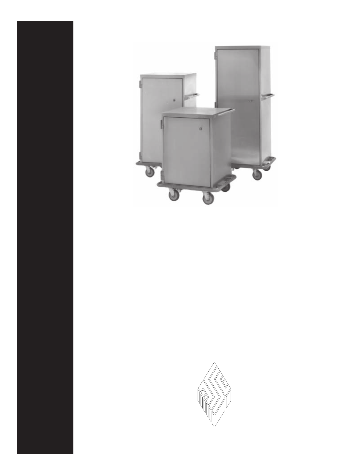
Tote-Al Case Carts,
Single-door Models
New Model Numbers:
105482-00 105483-00 105487-00 105582-00 105583-00 105587-00
Owner’s Manual
Former Model Number:
105587-00
Durable, heli-arc welded, stainless steel
33 in., 48 in., and 60 in. cabinet heights
Wide selection of shelf and drawer options
External or recessed handles
SSCI
Wheeling, IL (800) 323 7366
Form No. 702730 Rev. A 11/06
Page 2

© Copyright 2006 by Suburban Surgical Co., Inc. All rights reserved.
No part of this document may be reproduced or utilized in any form or by any means, electronic or mechanical, including
photocopying, recording, or by any information storage and retrieval system without written permission.
Inquiries should be addressed to Suburban Surgical Co., Inc.
Wheeling, Illinois 60090, USA
Page 3

Owner’s Manual - Tote-Al Case Carts - Single-door Models
Table of Contents
Chapter 1 - General Information ................................................................... 1
Introduction ........................................................................................................................ 1
About this Manual .............................................................................................................. 1
Information and Safety Notices .......................................................................................... 2
Notes ....................................................................................................................... 2
CAUTIONS ............................................................................................................ 2
SSCI Contact Information .................................................................................................. 2
Models ................................................................................................................................ 3
Cabinet Sizes .......................................................................................................... 3
Handle Options ....................................................................................................... 3
Model Part Numbers ............................................................................................... 4
Shelf Options .......................................................................................................... 4
Top Extensions ....................................................................................................... 5
Accessories ......................................................................................................................... 5
General.................................................................................................................... 5
Optional Drawers .................................................................................................... 6
Returning the Case Cart for Repairs ................................................................................... 7
RMA Numbers........................................................................................................ 7
Packing and Shipment ............................................................................................ 7
Warranty.............................................................................................................................. 7
Chapter 2 - Unpacking and Assembly .......................................................... 9
General................................................................................................................................ 9
Unpacking and Inspection .................................................................................................. 9
Shelf Installation ................................................................................................................. 9
Adjustable Shelves ................................................................................................. 9
Roll-out Shelves ................................................................................................... 10
Chapter 3 - Using Your Case Cart............................................................... 13
Opening, Latching, and Closing the Door ........................................................................ 13
Opening the Door ............................................................................... 13
Latching the Door in the Full-open Position ...................................... 13
Unlatching the Door from the Full-open Position .............................. 13
Closing the Door ................................................................................. 13
Rolling Shelves ..................................................................................................... 14
In and Out ............................................................................................................. 14
Removing and Replacing Roll-out Shelves .......................................................... 14
Using Roll-out Shelves ..................................................................................................... 14
Locking and Releasing Roll-out Shelves .............................................................. 14
Rolling Shelves In and Out ................................................................................... 14
Form No. 702730 Rev. A November, 2006 i
Page 4

Table of Contents
Removing and replacing Toll-out Shelves ............................................................ 14
Removal .............................................................................................. 14
Replacement ....................................................................................... 15
Adjusting Shelf Height ..................................................................................................... 16
Adjustable Shelves ............................................................................................... 16
Roll-out Shelves ................................................................................................... 16
Removing and Replacing Shelves .................................................................................... 17
Adjustable Shelves ............................................................................................... 17
Roll-out Shelves ................................................................................................... 17
Using the Caster Swivel Locks ......................................................................................... 17
Locking the Swivel ............................................................................. 17
Unlocking the Swivel ......................................................................... 18
Chapter 4 - Repairs and Replacements..................................................... 19
Replacement Parts ............................................................................................................ 19
General.............................................................................................................................. 20
Parts Ordering Procedure .................................................................................................. 20
Parts Replacement Procedures.......................................................................................... 21
Removing and Installing a Case Cart Door .......................................................... 21
Overview ............................................................................................ 21
Removal .............................................................................................. 21
Installation .......................................................................................... 21
Lower Door Hinge ................................................................................................ 22
Overview ............................................................................................ 22
Tools Required .................................................................................... 22
Procedure ............................................................................................ 22
Casters .................................................................................................................. 23
Overview ............................................................................................ 23
Tool Required ..................................................................................... 23
Procedure ............................................................................................ 23
Latch Striker Plate ................................................................................................ 24
Overview ............................................................................................ 24
Tools Required .................................................................................... 24
Procedure ............................................................................................ 24
Handle Catch ........................................................................................................ 25
Overview ............................................................................................ 25
Tools Required .................................................................................... 25
Procedure ............................................................................................ 25
Knob Handle ......................................................................................................... 26
Latch Bolt ............................................................................................................. 26
Latch Bolt Spring .................................................................................................. 26
Overview ............................................................................................ 26
Tool Required ..................................................................................... 26
Procedure ............................................................................................ 26
ii
SSCI - Suburban Surgical Company, Inc.
Page 5

Owner’s Manual - Tote-Al Case Carts - Single-door Models
Bumper (Complete with Vinyl Insert) .................................................................. 27
Overview ............................................................................................ 27
Tools Required .................................................................................... 27
Procedure ............................................................................................ 27
Adjustable Shelf ................................................................................................... 28
Overview ............................................................................................ 28
Procedure ............................................................................................ 28
Roll-out Shelf ....................................................................................................... 28
Overview ............................................................................................ 28
Procedure ............................................................................................ 28
Roll-out Shelf Track ............................................................................................. 28
Overview ............................................................................................ 28
Procedure ............................................................................................ 28
Rollers for Roll-out Shelves and Tracks............................................................... 29
Overview ............................................................................................ 29
Tools Required .................................................................................... 29
Procedure ............................................................................................ 29
Care of Wheel/Caster Assemblies .................................................................................... 30
Overview .............................................................................................................. 30
Inspection.............................................................................................................. 30
Equipment Frames and Fasteners ....................................................... 30
Casters ................................................................................................ 30
Wheels ................................................................................................ 30
Swivel Locks ...................................................................................... 31
Lubrication............................................................................................................ 31
Recommended Lubricants .................................................................................... 31
Power Towed Operation ....................................................................................... 31
Form No. 702730 Rev. A November, 2006 iii
Page 6

Table of Contents
Comments:
iv
SSCI - Suburban Surgical Company, Inc.
Page 7
Owner’s Manual - Tote-Al Case Carts - Single-door Models
Chapter 1 - General Information
Introduction
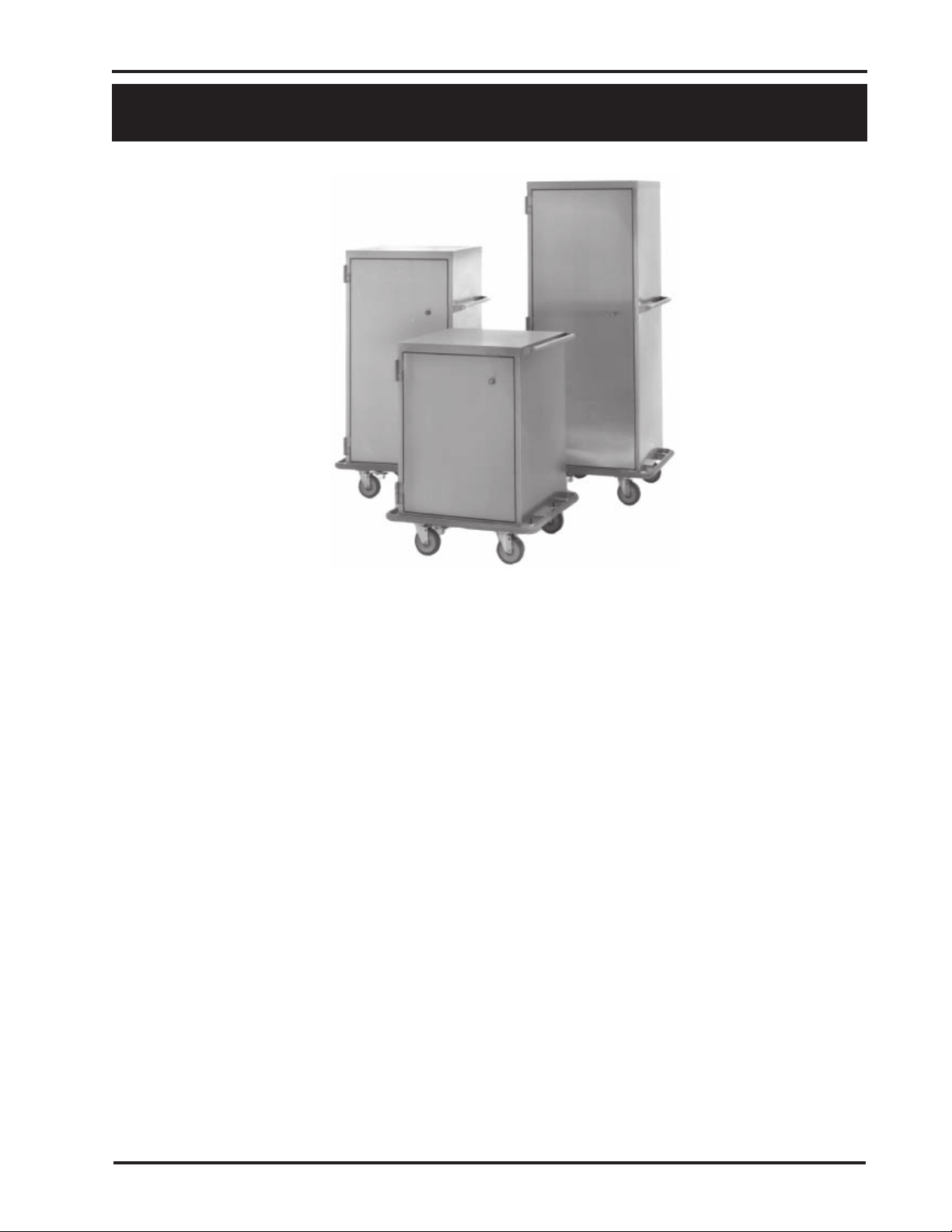
An SSCI Case Cart is ideal for keeping all the supplies needed
for individual procedures close at hand. Simply load it with
sterile instruments, surgical packs, surgical drapes, sutures, and
other supplies and wheel it to the surgical suite. When the
procedure is complete, all items delivered to the surgical suite
within the Case Cart are to be repackaged inside the Case Cart
for return to the sterile processing department. Then, after
washing, quickly and easily restock the Case Cart with sterile
instruments, surgical packs, surgical drapes, sutures, and other
supplies for the next surgical procedure or emergency.
You will appreciate the exceptional quality of SSCI’s stainless
steel Case Carts. We start with heavy-gauge, Type 304 stainless
steel, formed, heli-arc welded, and then polished to a smooth,
even finish. We then incorporate a host of construction features
for industrial-strength durability and exceptionally easy care.
SSCI Tote-Al Case Carts can be designed and sized with couplers
and signage compatible with all cart transfer and lift systems.
About this Manual
Form No. 702730 Rev. A November, 2006
Every attempt has been made to insure that the information in
this manual is correct and complete. SSCI, however, always
welcomes our customer’s suggestions for improvements to our
products and associated publications.
1
Page 8

Chapter 1 - General Information
Information and
Safety Notices
CAUTIONS
Notes
In this manual you will find text under the headings Note:, and
CAUTION:.
Under Note: headings, you will be given additional information
pertinent to the subject discussed in that paragraph or step.
Example:
Stainless steel is steel alloyed with chromium to make
it highly resistant to stain, rust, and corrosion.
Note: This does NOT mean, however, that stainless
steel will never rust or corrode.
Under CAUTION: headings, you will be alerted to potentially
hazardous conditions which, if ignored or mishandled, could
result in injury to yourself or damage to the equipment.
Example:
SSCI Contact
Information
CAUTION: Unpacking the case cart is not
difficult. The cart is heavy, however, and
handling it can be awkward for one person.
We recommend that unpacking be done by
at least two people.
Contact SSCI Customer Service by mail, telephone, or fax. The
department is available from 8:30am to 5:00pm, Central Time,
Monday through Friday. Closed holidays.
Address: Suburban Surgical Co., Inc.
275 Twelfth Street
Wheeling, Illinois 60090
Telephone: Illinois - (847) 537-9320, ext. 3518
Toll Free - (800) 323-7366
Fax: (847) 537-9061
Web: www.suburbansurgical.com
2
SSCI - Suburban Surgical Company, inc.
Page 9
Owner’s Manual - Tote-Al Case Carts - Single-door Models
Models
There are six basic models of single-door case carts varying by
cabinet size and handle options. All doors are hinged left. Carts
can be configured with one or two optional shelves.
Cabinet Sizes
Case cart cabinets are all 24.867 in. long and 24 in. wide. Carts
are available in three cabinet heights: 33 in., 48 in., and 63 in.
Handle Options
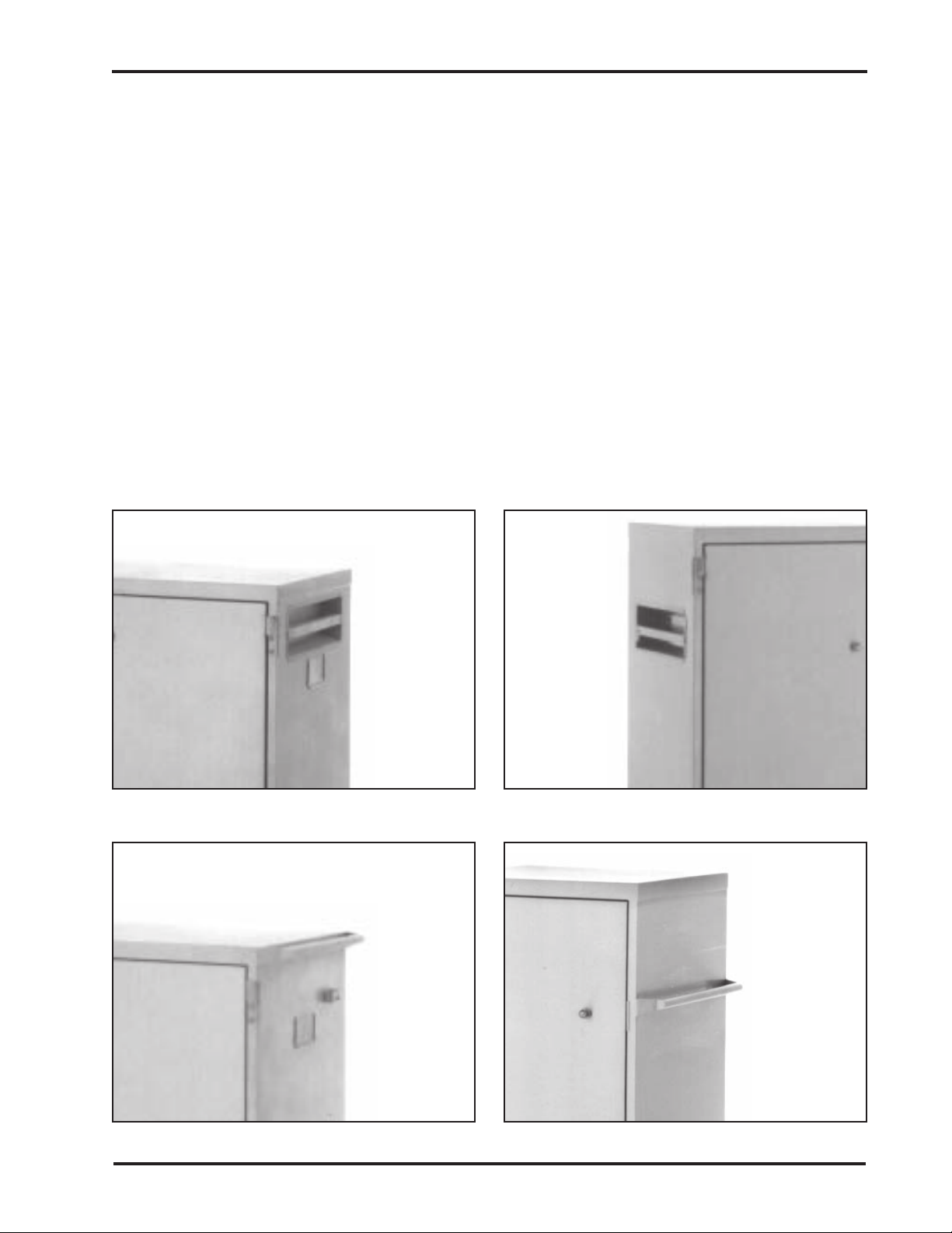
Four handle options are available for your case cart:
Style A - Recessed handle, near the top of the case cart -
Style B - Recessed handle, spaced down from the top
Style C - External handle, near the top of the case cart -
Style D - External handle, spaced down from the top of
Recessed Handle Near Top of Case Cart
for 33 in. high cabinets (Figure 1).
of the case cart - for 48 in. and 63 in. high
cabinets (Figure 2).
for 33 in. high cabinets (Figure 3).
the case cart - for 48 in. and 63 in. high cabinets
(Figure 4).
Figure 1. Style A Handles
External Handle Near Top of Case Cart
Figure 3. Style C Handles
Recessed Handle Spaced Down from
Top of Case Cart
Figure 2. Style B Handles
External Handle Spaced Down from
Top of Case Cart
Figure 4. Style D Handles
Form No. 702730 Rev. A November, 2006
3
Page 10
Chapter 1 - General Information
Model Part Numbers
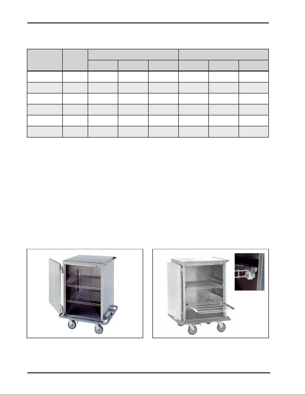
The SSCI part numbers, handle styles, and dimensions of the
six single-door case carts are listed in Table 1.
traPtraC
rebmuN
00-784501A"768.42"42"33"526.82"573.72"573.93
00-284501 B "768.42 "42 "84 "526.82 "573.72 "573.45
00-384501B"768.42"42"36"526.82"573.72"573.96
00-785501 C "768.42 "42 "33 "526.03 "573.72 "573.93
00-285501D"768.42"42"84"526.03"573.72"573.45
00-385501 D "768.42 "42 "36 "526.03 "573.72 "573.96
eldnaH
elytS
htgneL htdiW thgieH htgneL htdiW thgieH
snoisnemiDtenibaC snoisnemiDllarevO
Table 1. Single-door Case Carts - Part Numbers and Dimensions
Shelf Options
SSCI provides a variety of shelving options for your case cart.
Three types of shelves are available: wire, solid, and perforated.
All three types are available in adjustable or roll-out styles.
All shelves, both adjustable and roll-out, are adjustable for height.
Wire shelves are stainless steel rod, heli-arc welded at all intersections. Solid and perforated shelves are 18 gauge, stainless steel.
Figure 5 shows a single-door case cart with adjustable wire
shelves, and Figure 6 shows a similar cart with roll-out wire
shelves.
Part numbers for the various shelf options are shown in Table 2.
Figure 5. Single-door Case Cart with
Adjustable Wire Shelves
Figure 6. Single-door Case Cart with
Roll-out Wire Shelves (Rollers Shown in
Inset)
4
SSCI - Suburban Surgical Company, inc.
Page 11
Owner’s Manual - Tote-Al Case Carts - Single-door Models
noitpOflehS rebmuNtraPICSS
Top Extensions
elbatsujdA,flehSeriW
elbatsujdA,flehSdiloS
elbatsujdA,flehSdetarofreP
tuo-lloR,flehSeriW
tuo-lloR,flehSdiloS
tuo-lloR,flehSdetarofreP
00-003022
00-013022
00-023022
00-033022
00-043022
00-053022
Table 2. Single-door Case Carts - Shelf Options
Part Numbers
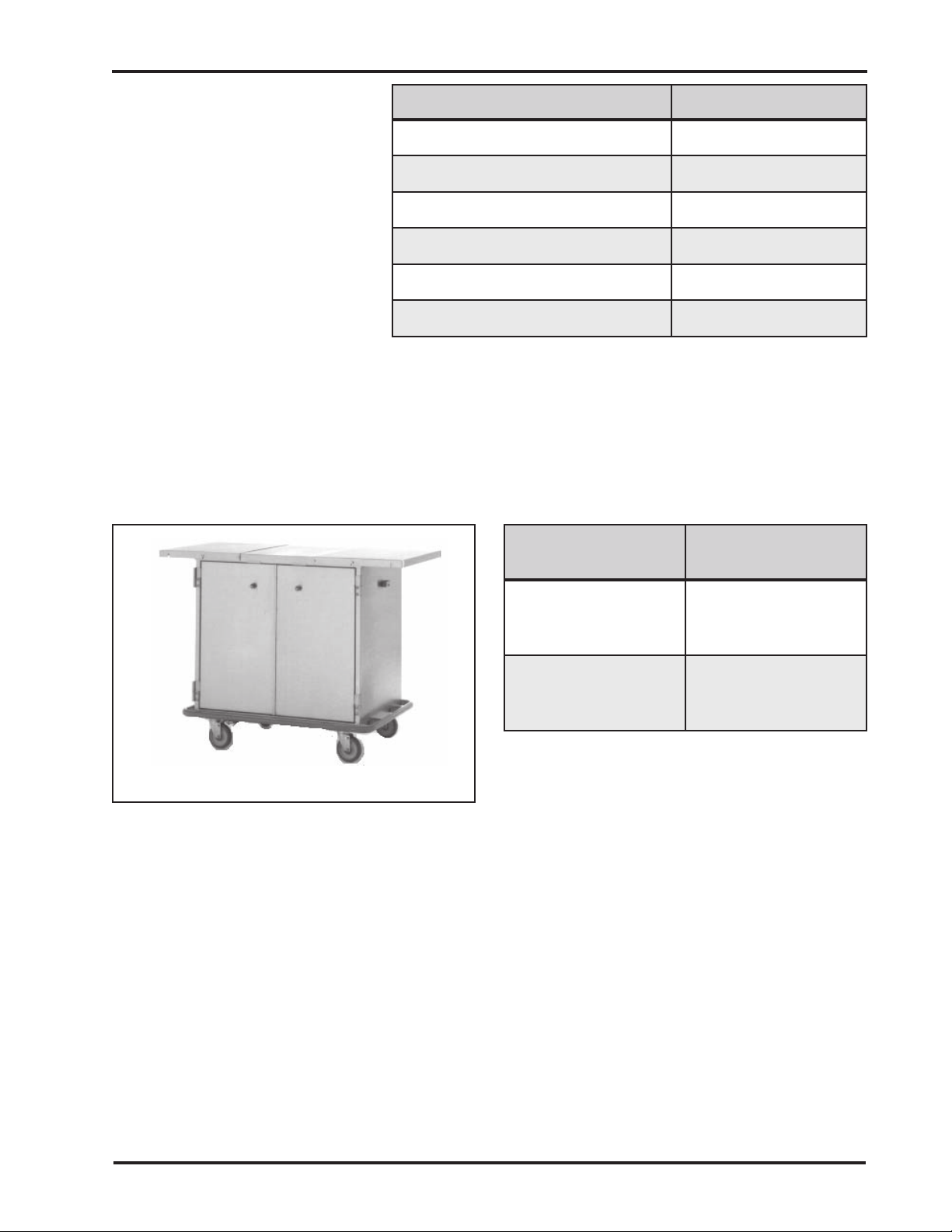
New single-door case carts can be ordered with extended tops.
These extensions increase the length of the top by 14.125 in. on
each end (Figure 7). The extension tops are 18 gauge, stainless
steel. Extension top part numbers are shown in Table 3.
rebmuNtraPtraC
poTnoisnetxE
rebmuNtraP
Note: Double-door cart shown,
single-door cart extended top similar.
Figure 7. Extended Top
Accessories
General
00-784501
00-284501
00-384501
00-785501
00-285501
00-385501
00-004022
00-014022
Table 3. Extension Top Part Numbers
A variety of accessories can be ordered to increase the
functionality of your case cart:
Card holders (open on top edge):
5 in. W x 3 in. H - 600013
6 in. W x 4 in. H - 603673
8 in. W x 5 in. H - 601495
Custom-sized card holders available
Two-digit signage plates - 617375
Sign “THIS END ENTERS LIFT FIRST” - 610794
Sign “OTHER END ENTERS LIFT FIRST” - 617525
Drawers (refer to Optional Drawers on Page 6)
Form No. 702730 Rev. A November, 2006
5
Page 12
Chapter 1 - General Information
Optional Drawers
Drawer
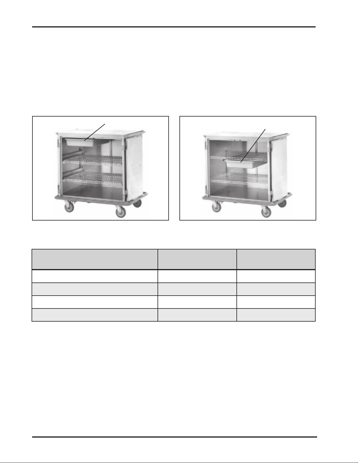
Two types of optional drawers are available for the case cart:
drawers that mount inside the cart under the top (Figure 8), and
drawers that mount under one of the shelves (Figure 9).
Drawers are made of ABS or fiberglass reinforced plastic.
All runners are stainless steel.
ABS drawers can be ordered ribbed with vertical channels to
accommodate divider strips, or non-ribbed. Fiberglass
reinforced plastic drawers can be autoclaved to 250° F. constant.
Drawer
Figure 8. Optional Drawer Mounted
Under the Case Cart Top
noitacoLrewarD SBA
poTtraCesaCrednU042-034022042-534022
flehSeriWelbatsujdArednU 042-134022 042-634022
sevlehSdetarofreP&diloSelbatsujdArednU042-234022042-734022
flehSeriWtuo-lloRrednU 042-334022 042-824022
Table 4. Part Numbers for Optional Drawers
Figure 9. Optional Drawer Mounted
Under a Shelf
decrofnieRssalgrebiF
citsalP
6
SSCI - Suburban Surgical Company, inc.
Page 13

Returning the Case
Cart for Repairs
Owner’s Manual - Tote-Al Case Carts - Single-door Models
Warranty
RMA Numbers
Packing and
Shipment
If your case cart should require return to SSCI for repairs,
discuss the problem with one of our Customer Service
Representatives. Obtain an RMA number (Return Merchandise
Authorization) from them before shipping the unit back.
Note: Merchandise returned without an RMA number will not
be accepted.
Package the case cart securely, and ship documentation with
the cart including:
Destination
RMA Number
Your name, company, and address
Your telephone number
A description of the reason for returning the cart
Suburban Surgical Company, Inc. warrants the original
purchaser that all equipment manufactured by Suburban
Surgical Company, Inc. will be of the highest standards in
material and workmanship. All equipment manufactured by
Suburban Surgical Company, Inc. will be warrantied for a
period of one (1) year from the date of shipment from the
factory.
Components and casters Suburban Surgical Company, Inc.
purchases from other manufacturers will be covered by the
respective manufacturer’s Warranty.
Warranties will not apply if it is determined by Suburban
Surgical Company, Inc. that the equipment became defective
due to an accident, misuse, abuse, or alteration. Warranties do
not include freight charges for replacement or repair.
Form No. 702730 Rev. A November, 2006
7
Page 14

Chapter 1 - General Information
Comments:
8
SSCI - Suburban Surgical Company, inc.
Page 15

Owner’s Manual - Tote-Al Case Carts - Single-door Models
Chapter 2 - Unpacking and Assembly
General
Unpacking and
Inspection
Shelf Installation
SSCI Case Carts are shipped fully assembled except for
optional shelves which must be installed on-site. If you have
problems or require additional assistance, please feel free to
call SSCI Customer Service at (800) 323-7366.
CAUTION: Unpacking the case cart is not difficult.
The cart is heavy, however, and handling it can be
awkward for one person. We recommend that
unpacking be done by at least two people.
If the shipping container appears damaged in any way, contact
the shipping company immediately. Save all damaged packing
materials to assist in proving liability for damage.
Carefully inspect your case cart while you unpack it. If any
damage is noted, or if parts appear to be missing, call SSCI
Customer Service at (800) 323-7366.
Wire, solid, and perforated shelves are all installed in the same
way. There are differences, however, in the installation
procedures for adjustable and roll-out shelves.
Adjustable Shelves
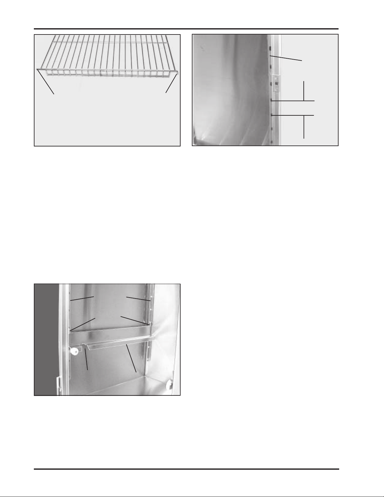
Observe the shelf (Figure 10) and notice that on the front and
rear shelf rods, the left end is straight and the right end is bent
down at a 90° angle. Also note that the rear of the shelf is
flanged up (to keep items from falling off when the shelf is
moved), and the front is flanged down. Notice also, the vertical
shelf bracket mounted to each inside corner of the cart (Figure 11).
A series of oblong holes in the vertical brackets are spaced about
three inches apart. The ends of the shelf rods fit into these holes.
To install adjustable shelves:
1. Open the case cart door.
2. Put the shelf into the cabinet (flanged-up side to the
rear) with the right side tilted up at about a 45° angle.
3. Place the straight (left) rod ends into the holes in the left
front and rear vertical brackets at the desired level.
Form No. 702730 Rev. A November, 2006 9
Page 16
Chapter 2 - Unpacking and Assembly
Front - flanged down
Straight End
(left)
Front Shelf Rod Shown - Rear Same
90° End
(right)
Shelf
Bracket
(1 each
corner)
mm
m
mm
3 in.
kk
k
kk
Figure 10. Adjustable Shelf
4. Lower the 90° ends (right) and engage the rod ends into
Roll-out Shelves
Vertical
Brackets
Hooks
Gap
Figure 12. Roll-out Shelf Track and
Vertical Brackets
Roll-out Shelf
Track
Mounting a roll-out shelf is a two-step procedure: (1) mounting
the two roll-out shelf tracks, and (2) installing the shelf.
Notice the vertical shelf bracket mounted to each inside corner
of the cart (Figure 11). A series of oblong holes in the vertical
brackets are spaced about three inches apart. The hooks on the
roll-out shelf tracks fit into these holes. To install roll-out
shelves:
Figure 11. Shelf Bracket
the right vertical bracket holes. Note: Make sure the
shelf is level side-to-side and front-to-rear.
1. Open the case cart door.
2. Make sure that the shelf lock is pivoted
up to the release position (Figure 15).
3. Hook both roll-out shelf tracks to the
front and rear vertical brackets at the
desired level (Figure 12). Note: Make
sure that the gaps in the roll-out shelf
tracks are to the front.
4. Tilt the front of the shelf upward to
almost vertical, and insert the rear
edge into the cabinet.
5. Slide the lower rollers down through the
gaps in the roll-out shelf tracks.
10
SSCI - Suburban Surgical Company, Inc.
Page 17

Owner’s Manual - Tote-Al Case Carts - Single-door Models
6. Lower the front of the shelf to near horizontal.
7. When all rollers are properly positioned, roll the shelf
back into the cabinet.
8. Slide the shelf back and forth a few times to make sure
it operates smoothly.
9. Slide the shelf all the way into the cabinet.
10. Pivot the shelf lock down to the lock position (Figure 16).
11. Close the door.
Form No. 702730 Rev. A November, 2006 11
Page 18

Chapter 2 - Unpacking and Assembly
Comments:
12
SSCI - Suburban Surgical Company, Inc.
Page 19
Owner’s Manual - Tote-Al Case Carts - Single-door Models
Chapter 3 - Using Your Case Cart
Opening, Latching,
and Closing the Door
Opening the Door
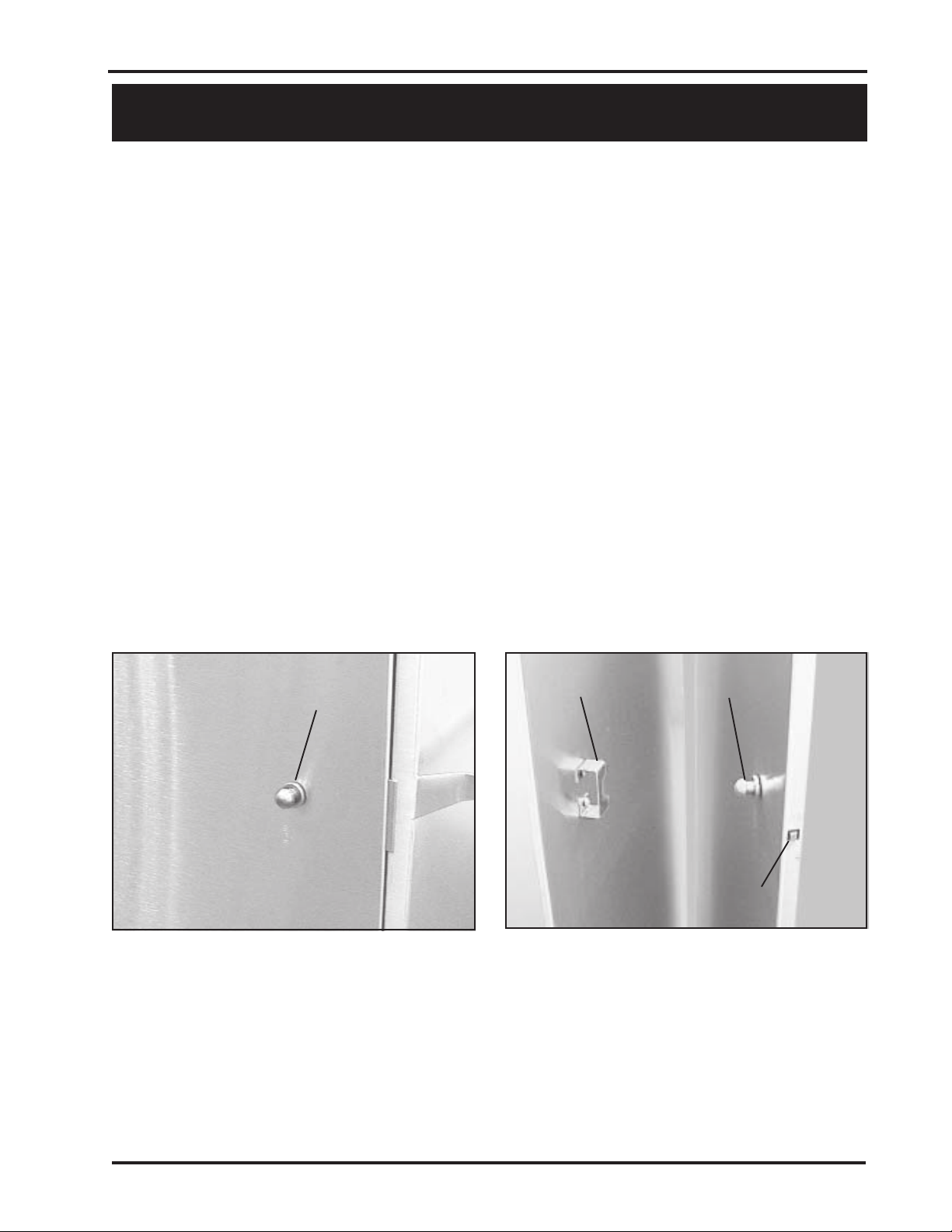
To open the door, push the knob handle to the left (Figure 13)
and swing the door open.
Latching the Door in the Full-open Position
The door can be opened a full 270° to lie flat against the side of
the cart and can be latched in that position for greater convenience
when loading or cleaning. When latched, the knob handle engages
either a catch on the side of the cart (Figure 14) or the recessed
handle (depending on case cart model) and is held in the full-open
position.
Unlatching the Door from the Full-open Position
Press in on the latch tongue (Figure 14) and pull the door free
of the catch (or recessed handle).
Closing the Door
The door can be pushed closed and will lock. It may be easier,
however, to press the knob handle to the left and then push the
door closed.
Knob Handle
pp
p
pp
Figure 13. Opening the Door
Catch Knob Handle
pp
p
pp
pp
p
pp
Latch Tongue
pp
p
pp
Figure 14. Latching the Door in the Fullopen Position
Form No. 702730 Rev. A November, 2006
13
Page 20
Chapter 3 - Using Your Case Cart
Using Roll-out
Shelves
Locking and
Releasing Roll-out
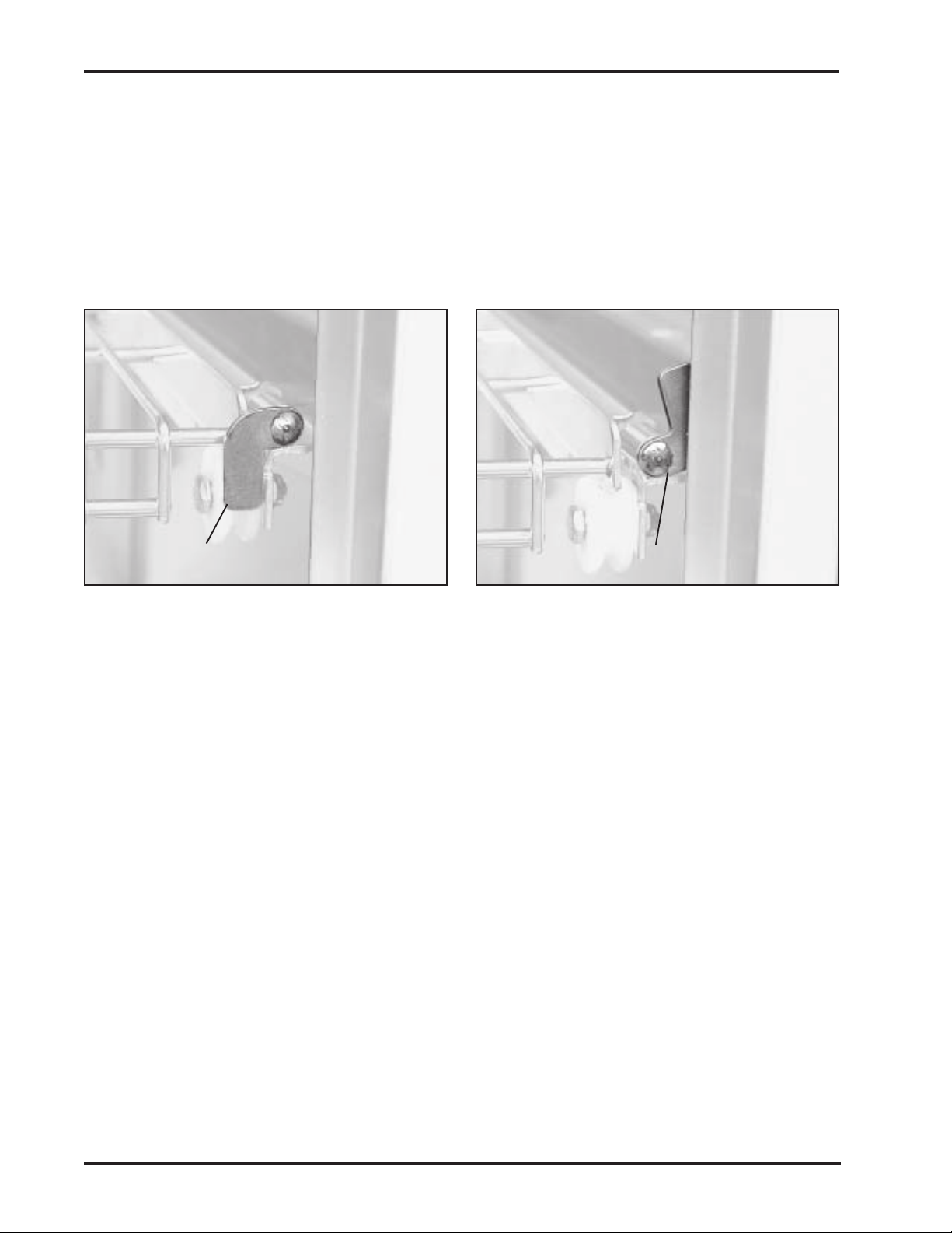
Pivot UP to Release
EE
E
EE
Shelves
The following information is valid for wire, solid, and
perforated shelves.
Roll-out shelves have a built-in lock to hold them securely in
place so that they do not roll out of the cabinet when not
intended. A two-position pivot lock located on the front of the
shelf on the right side holds the shelves in place, or releases
them when required. Pivot the lock up to release the shelf
(Figure 15), or down to lock it (Figure 16).
Pivot DOWN to Lock
FF
F
FF
Shelf Lock
Figure 15. Shelf Lock in Lock Position
Rolling Shelves
In and Out
Removing and
Replacing Roll-out
Shelves
Roll-out shelves ride on polyethylene rollers and, when rolled
out, extend 14.75 in. past the cart’s face to a positive stop
preventing accidental removal. The rear edge of each shelf is
flanged up to prevent stored items from falling off the back as the
shelf is rolled out.
Before attempting to roll the shelf out, pivot the shelf lock upward
to the release position (Figure 15). After rolling the shelf back into
the cabinet, be sure to pivot the shelf lock down to the lock
position (Figure 16).
It will occasionally be necessary to remove a roll-out shelf for
cleaning, height adjustment, etc.
Removal
1. Open the cabinet door and latch it back (Figure 14).
Shelf Lock
Figure 16. Shelf Lock in Release
Position
2. Pivot the shelf lock up to the release position (Figure 15).
14 SSCI - Suburban Surgical Company, Inc.
Page 21

Owner’s Manual - Tote-Al Case Carts - Single-door Models
Note: The shelf rollers ride on a roll-out shelf
track on either side of the cabinet. Notice that on
each track there is a 1.25 in. gap about 2.5 in.
back from the front end (Figure 17).
Gap
Roll-out Shelf
Track (both
sides)
Figure 17. Roll-out Shelf Track
3. Roll the shelf out until the front lower
rollers approach the gaps.
4. Tilt the shelf up and pull it outward,
allowing the lower rollers to come out
through the gaps.
5. Remove the shelf from the cabinet.
Replacement
1. Tilt the front of the shelf upward to almost vertical and
insert the rear edge into the cabinet.
2. Slide the lower rollers through the gaps in the roll-out
shelf tracks.
3. Lower the front of the shelf to horizontal.
4. When all rollers are properly positioned, roll the shelf
back into the cabinet.
5. Slide the shelf back and forth a few times to make sure
it operates smoothly.
6. Slide the shelf all the way into the cabinet.
7. Pivot the shelf lock down to the lock position (Figure 16).
8. Close the door.
Form No. 702730 Rev. A November, 2006
15
Page 22
Chapter 3 - Using Your Case Cart
Adjusting Shelf
Height
Adjustable Shelves
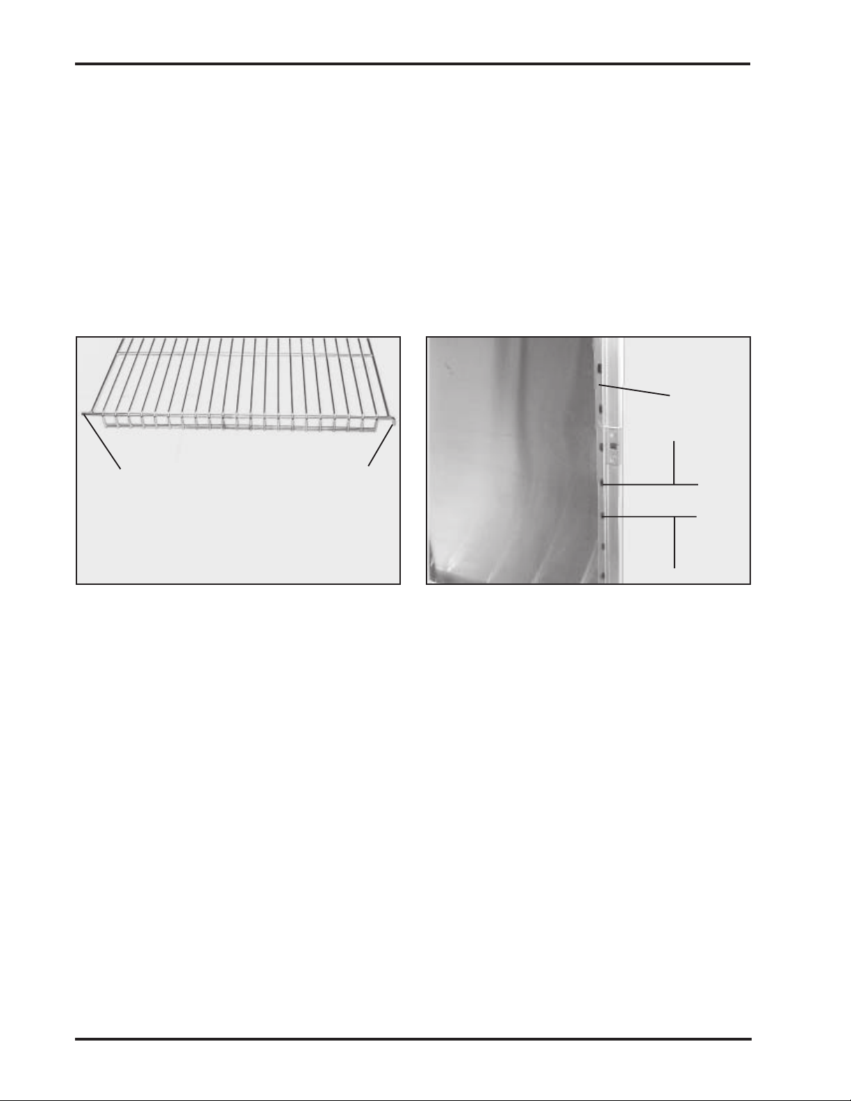
Straight End 90° End
Adjustment points are provided in the case cart to allow you to
adjust the shelves up and down to suite your needs. Shelf
positions are spaced about 3 in. apart, and the number of
positions varies with the height of the cabinet. Both adjustable
and roll-out shelves can be adjusted for height.
Observe the shelf (Figure 18) and notice that on the front and
rear shelf rods, one end is straight and the opposite end is bent
down at a 90° angle. Notice also, the vertical shelf bracket in
each inside corner of the cart (Figure 19). A series of oblong
holes in the vertical brackets are spaced about three inches
apart. The ends of the shelf rods fit into these holes.
Shelf
Bracket
(1 each
corner)
mm
m
mm
3 in.
Front Shelf Rod Shown - Rear Same
Figure 18. Adjustable Shelf
Roll-out Shelves
kk
k
kk
Figure 19. Shelf Bracket
To move a shelf to a different level:
1. Lift up on the side of the shelf with the 90° rod ends
until you can remove the straight rod ends from the
bracket holes.
2. Place the straight ends into the holes at the desired level.
3. Lower the 90° ends and engage rod ends into the new
holes. Note: Make sure the shelf is level side-to-side
and front-to-rear.
Altering the height of a roll-out shelf requires removal of the
shelf from the cabinet. To alter the shelf height:
1. Remove the shelf from the cabinet (refer to Removing
and Replacing Roll-out Shelves - Removal, Steps 1
through 5, starting on Page 14).
16 SSCI - Suburban Surgical Company, Inc.
Page 23
Owner’s Manual - Tote-Al Case Carts - Single-door Models
Vertical
Brackets
Hooks
Gap
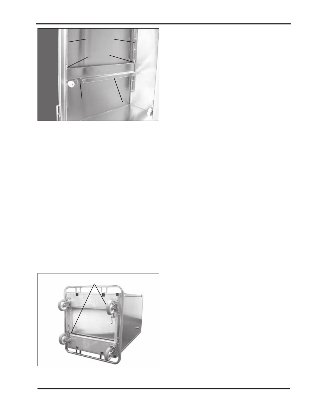
Figure 20. Roll-out Shelf Track and
Vertical Brackets
Removing and
Replacing Shelves
Adjustable Shelves
Roll-out shelf
track
It may occasionally be necessary to remove a shelf for cleaning,
height adjustment, etc. Removing and replacing the case cart
shelves are simple and easy.
To remove and replace an adjustable shelf, follow the
instructions under Adjusting Shelf Height - Adjustable Shelves
on Page 16.
2. Lift up on the roll-out shelf track and
unhook it from the front and rear vertical
brackets (Figure 20). Do this for both
roll-out shelf tracks.
3. Hook both roll-out shelf tracks to the
front and rear vertical brackets at the
desired level.
4. Replace the shelf onto the roll-out shelf
tracks (refer to Removing and Replacing
Roll-out Shelves - Replacement, Steps 1
through 8 on Page 15). Note: Make
sure the shelf is level side-to-side and
front-to-rear.
Roll-out Shelves
Using the Caster
Swivel Locks
Casters with Swivel Locks
To remove and replace a roll-out shelf, follow the instructions
under Removing and Replacing Roll-out Shelves - Removal,
Steps 1 through 5, starting on Page 14.
Two of the four casters on each case cart are equipped with
swivel locks to insure that the case cart runs straight without
turning. The casters with swivel locks are located on diagonally
opposite corners of the cart (Figure 21).
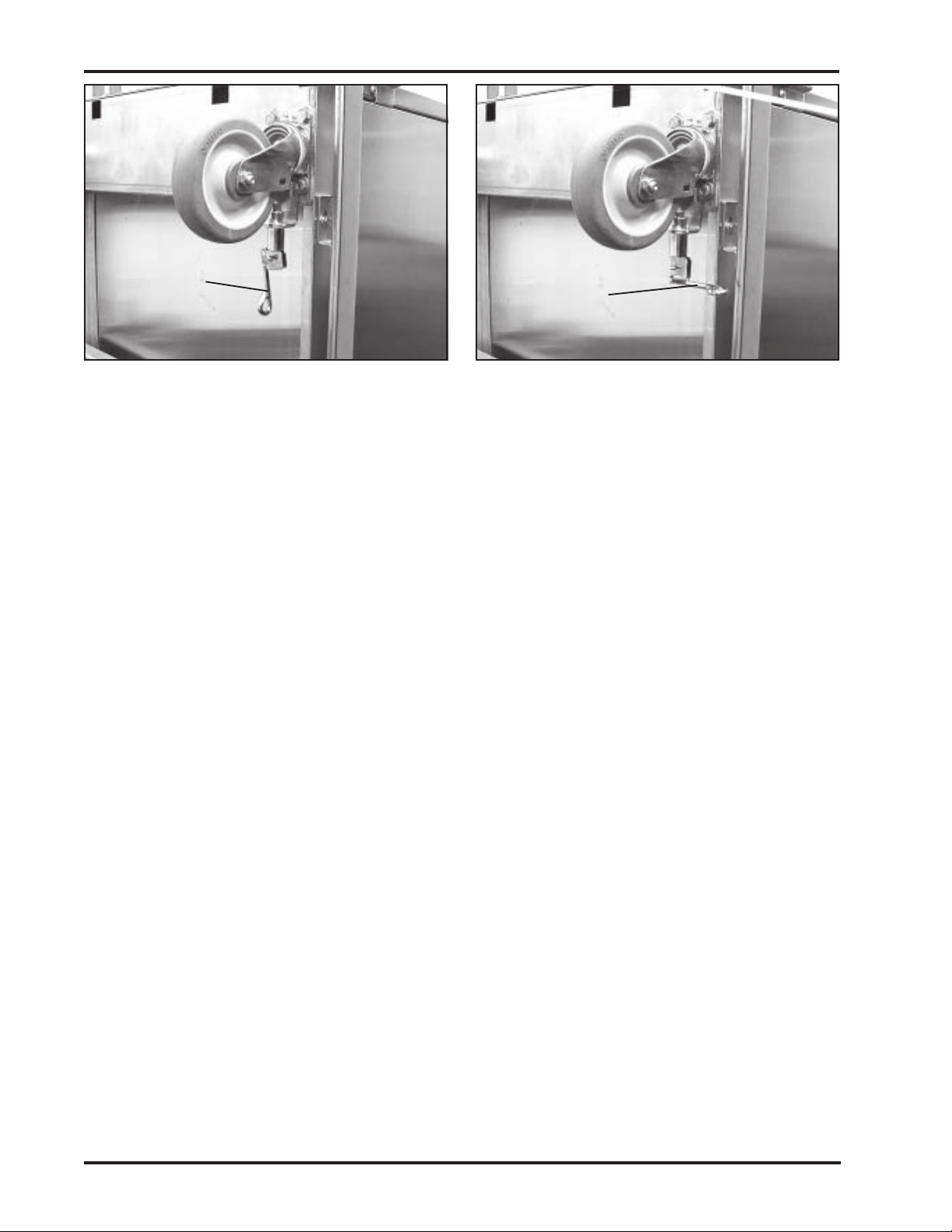
Locking the Swivel
To lock the swivel and prevent the caster from
turning, place the swivel lock (Figure 22) in the
straight out position. In this position, the end of
the lock enters a notch in the swivel body and
prevents it from turning.
Figure 21. Typical Case Cart
Form No. 702730 Rev. A November, 2006
17
Page 24
Chapter 3 - Using Your Case Cart
Swivel Lock
in Locked
Position
Figure 22. Caster with Swivel Lock Locked
Unlocking the Swivel
To unlock the swivel and allow the caster to turn, place the
swivel handle in the 90° position (Figure 23).
Swivel Lock
in Unlocked
Position
Figure 23. Caster with Swivel Lock Unlocked
18 SSCI - Suburban Surgical Company, Inc.
Page 25

Owner’s Manual - Tote-Al Case Carts - Single-door Models
Chapter 4 - Repairs and Replacements
Replacement Parts
emaNtraP rebmuNtraPICSS ytitnauQ
egniHrooDrewoL584306222egaP
kcoLleviwS/w,retsaC 00AAF-01111013-100C 2 32egaP
kcoLleviwSo/w,retsaC00AAF-01111012-100C232egaP
etalPrekirtShctaL
hctaCeldnaH
eldnaHbonK 994202 1 62egaP
tloBhctaL945157162egaP
gnirpStloBhctaL 604258 1 62egaP
Table 5 lists the replacement parts available for the case cart.
For parts not listed below, contact SSCI Customer Service at
(800) 323-7366. Refer to Parts Ordering Procedure on Page 20.
tnemecalpeR
snoitcurtsnI
880806-stenibaCH"33
437006-stenibaCH"36&"84
seldnaHlanretxEhtiwstraCesaCnO
083616-ylno
1 42egaP
1 52egaP
etelpmoC,repmuB
flehSeriWelbatsujdA 00-003022 yravnac 82egaP
flehSdiloSelbatsujdA00-013022yravnac 82egaP
flehSdetarofrePelbatsujdA 00-023022 yravnac 82egaP
flehSeriWtuo-lloR00-033022yravnac 82egaP
flehSdiloStuo-lloR 00-043022 yravnac 82egaP
flehSdetarofrePtuo-lloR00-053022yravnac 82egaP
kcarTflehStuo-lloR
kcarT&flehSrofsrelloRno42erugiFotrefer 02egaP92egaP
700012-tfeL
800012-thgiR
270302-sledoMeldnaHdesseceR
E270302-sledoMeldnaHlanretxE
1 72egaP
flehS/hcae1 82egaP
Table 5. Replacement Parts for SSCI Tote-All Single-door Case Carts
Form No. 702730 Rev. A November, 2006 19
Page 26
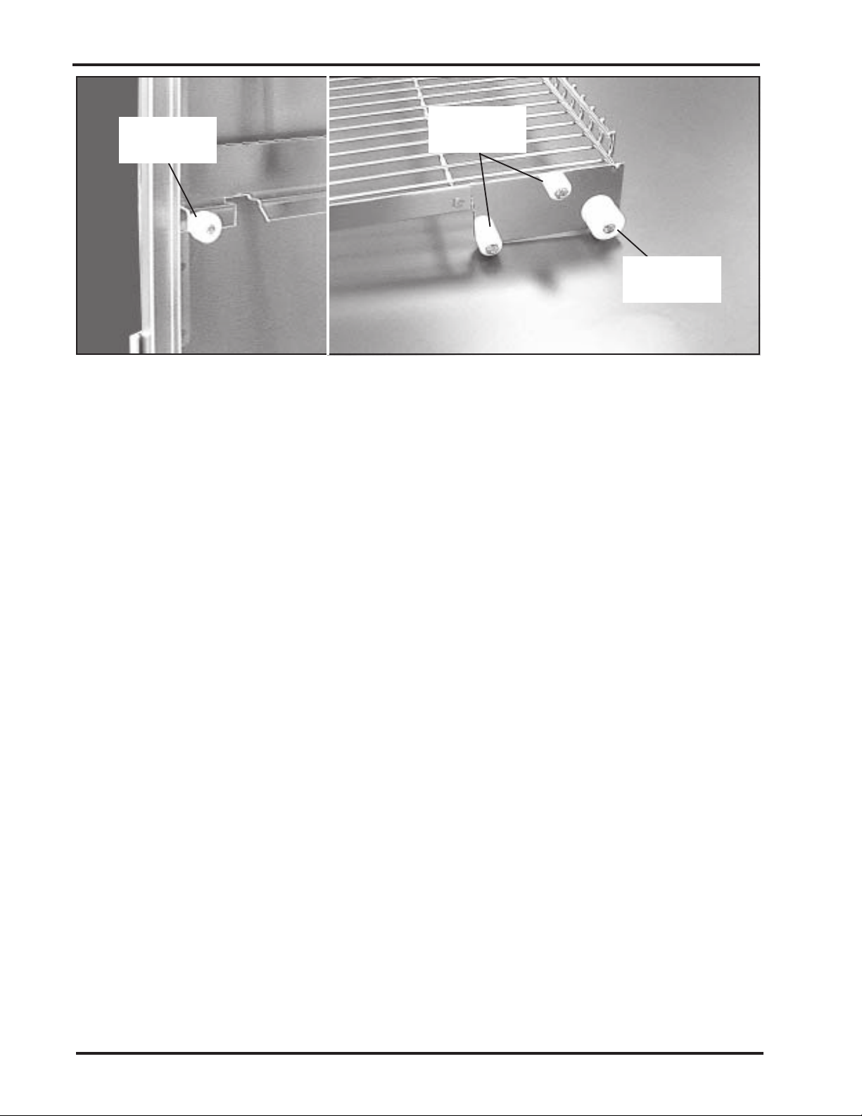
Chapter 4 - Repairs and Replacements
753332
1 per track
Roll-out Shelf Track
753333
4 per shelf
Roll-out Shelf
Figure 24. Part Numbers for Rollers on Roll-out Tracks and Shelves
General
Many threaded fasteners used on SSCI products are
secured with thread adhesive to insure structural integrity.
Removing any screw or bolt may be difficult at first.
If during disassembly, you remove any tape, cable ties,
etc., remember to replace them when the installation is
complete.
During disassembly, retain all hardware items such as
screws, nuts, lockwashers, etc. for reassembly.
If you have problems with any procedure, please feel
free to call SSCI Customer Service at (800) 323-7366.
753332
2 per shelf
Parts Ordering
Procedure
Order new equipment, accessories, and replacement parts direct
from SSCI. You can order by mail, telephone, or fax. Refer to
SSCI Contact Information on Page 2 for address, telephone,
and fax numbers. When ordering, please provide the following
information:
Your name
Company name
Company account number
Telephone number
Fax number
e-mail address
Shipping address
Billing address (if different from shipping address)
Names, part numbers, and quantities of items being
ordered
Credit card number and expiration date, or other
payment information
Preferred method of shipment
Information on whether the items are required on a
normal or urgent basis
20
SSCI - Suburban Surgical Company, Inc.
Page 27
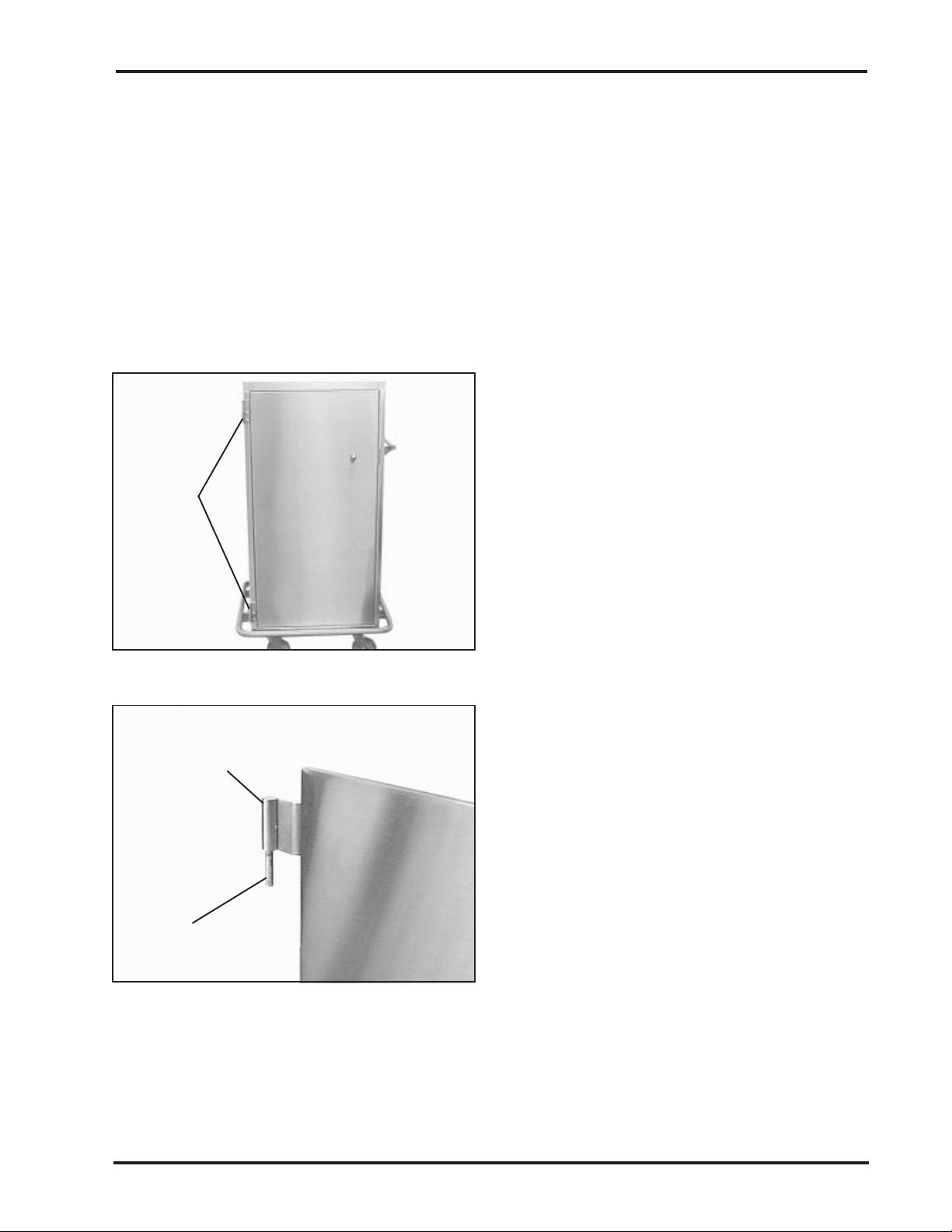
Parts Replacement
Procedures
Owner’s Manual - Tote-Al Case Carts - Single-door Models
Door
Hinges
Removing and
Installing a
Case Cart Door
Overview
Replacement of some case cart parts will require the removal
and subsequent reinstallation of the case cart door.
CAUTION: When working on the case cart, make
sure the wheels are blocked so that the cart cannot
move while you are working. Such movement could
create a hazardous condition.
Removal
1. Block or otherwise immobilize the case
cart wheels so that the cart can’t move
while you are working on it.
2. Unlatch and open the door.
CAUTION: The case cart door is heavy
and we recommend that removing and
installing the door be done by at least
two people.
Figure 25. Door Hinges
Top Half
of Hinge
Door
Hinge Pin
Figure 26. Top Half of Door Hinge
3. Lift up on the door until the upper and
lower hinge pins on the door disengage
from the lower hinge halves (Figures 25
and 26), and remove the door.
Installation
1. Lift up the door and gently lower both
hinge pins into the lower hinge halves
(Figure 26). Make sure the hinge pins
seat fully into the lower halves.
2. Swing the door open and closed a few
times to make sure it moves easily.
3. Close and latch the door.
Form No. 702730 Rev. A November, 2006 21
Page 28
Chapter 4 - Repairs and Replacements
Lower Door Hinge
P/N 603485
Overview
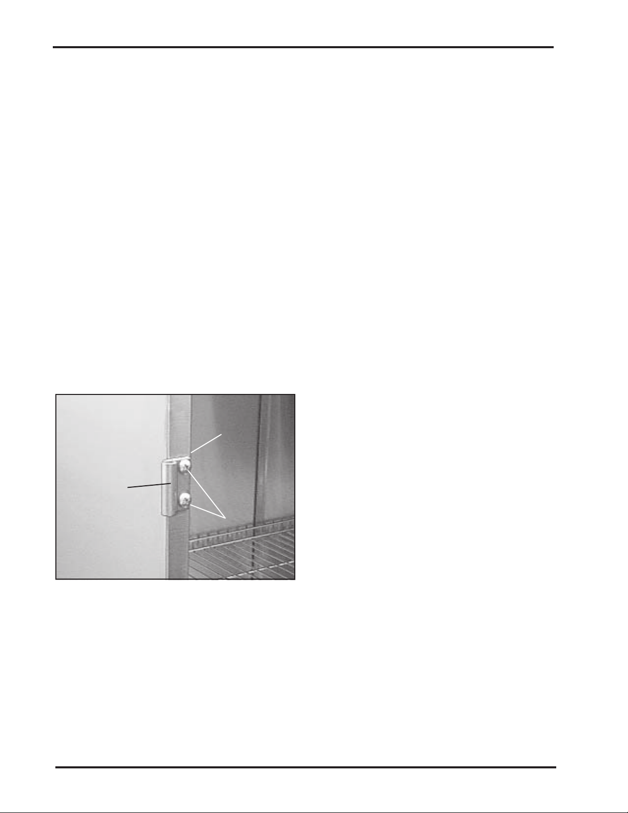
On all single-door case cart doors, each of the two hinges has
an upper and a lower half. The upper half is integral to the door
itself and cannot be replaced short of replacing the complete
door. The lower half is bolted to the case cart and can be
replaced if necessary. All hinges, upper and lower, on all singledoor case carts are identical.
Tools Required
Phillips screwdriver
Socket wrench, 7/16 in. socket, and 3 in. extension
Procedure
1. Remove the case cart door. Refer to Removing and
Installing a Case Cart Door - Removal, Steps 1
through 3 on Page 21. Observe the Cautions shown in
the procedure.
2. With a Phillips screwdriver and a socket wrench with a
7/16 in. socket on a 3 in. extension, remove the two
hinge mounting screws and nuts (Figure 27), and
remove the hinge.
Mounting
Nuts Inside
Lower
Door
Hinge
Hinge
Mounting
Screws
Figure 27. Lower Door Hinge and
Mounting Screws and Nuts
3. Hold the new hinge in place and secure
with the two mounting screws/nuts.
4. Replace the case cart door. Refer to
Removing and Installing a Case Cart
Door - Installation, Steps 1 through 3
on Page 21.
22
SSCI - Suburban Surgical Company, Inc.
Page 29
Owner’s Manual - Tote-Al Case Carts - Single-door Models
Casters
w/ Swivel Lock -
P/N C001-31011110-FAA00
w/o Swivel Lock -
P/N C001-21011110-FAA00
Overview
All case cart casters, either with or without swivel locks, are
removed and installed the same way.
Tool Required
1/2 in. wrench
Procedure
1. Make sure that the door is closed and latched.
CAUTION: The case cart is heavy. We recommend
that laying it down be done by at least two people.
2. Lay the case cart down on one side so that the caster
being removed is on top.
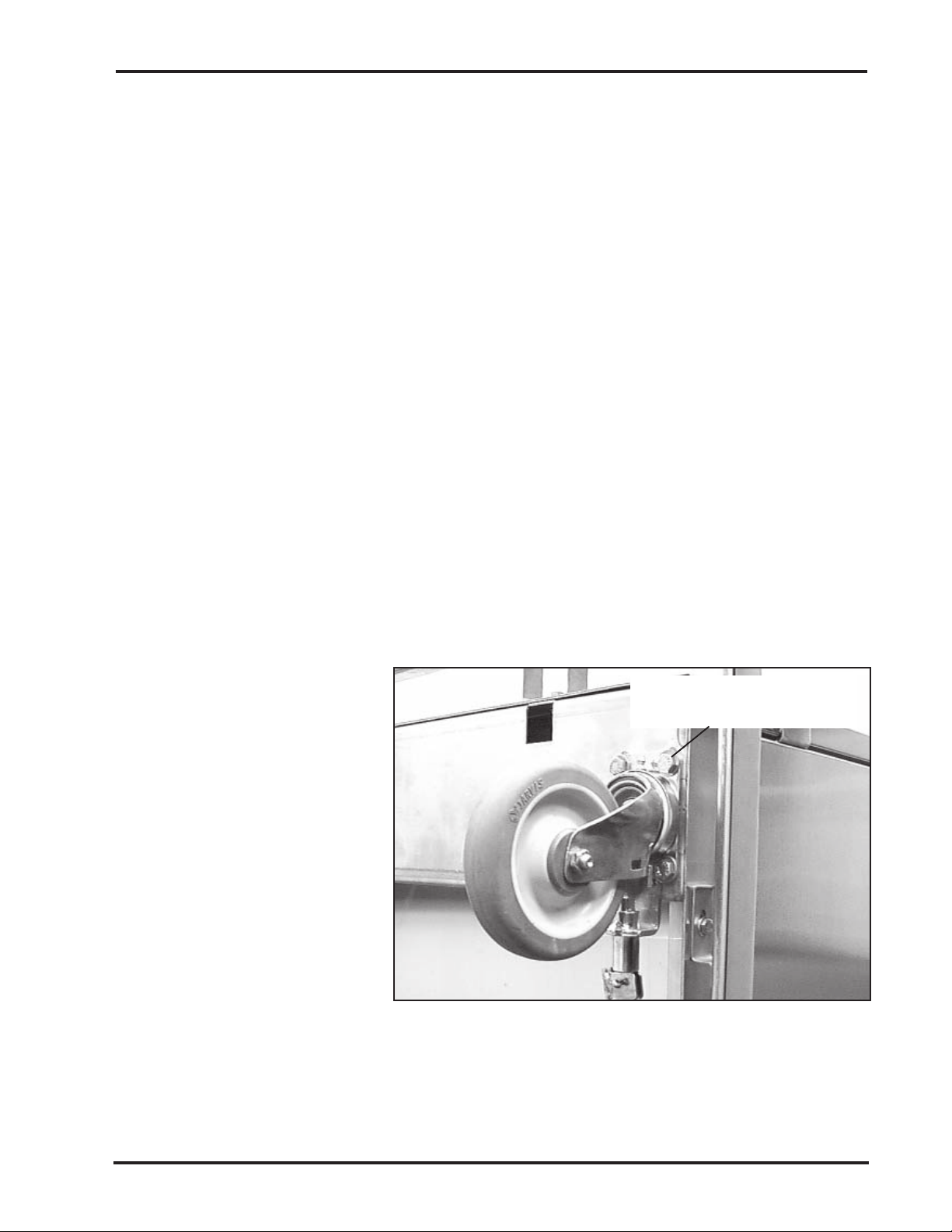
3. With a 1/2 in. wrench, remove the four mounting
screws/washers on the caster base (Figure 28).
4. Lift the complete caster assembly off the case cart.
5. Using the same screws/washers, mount the new caster
to the bottom of the case cart.
6. Stand the case cart back up to the upright position.
Caster Mounting Screw/
Washer (4)
Figure 28. Caster Mounting Screws (4)
Form No. 702730 Rev. A November, 2006 23
Page 30

Chapter 4 - Repairs and Replacements
Latch Striker Plate
33 in. H Cabinets -
P/N 608088
48 in. and 63 in. H Cabinets-
P/N 600734
Overview
Two types of striker plates are used on single-door case carts,
however, they are removed and installed in the same way.
Tools Required
Flat blade screwdriver
3/8 in. open-end or box-end wrench
Procedure
1. Unlatch and open the door.
2. With a flat blade screwdriver and a 3/8 in. open-end or
box-end wrench, remove the two striker plate mounting
screws and nuts (Figure 29), and remove the striker
plate.
3. Hold the new striker plate in place and secure with the
two mounting screws/nuts.
4. Close and latch the door.
Mounting
Nuts
Inside
Striker
Plate
Striker Plate
Mounting
Screws
Figure 29. Striker Plate and Mounting Screws/Nuts
24
SSCI - Suburban Surgical Company, Inc.
Page 31
Owner’s Manual - Tote-Al Case Carts - Single-door Models
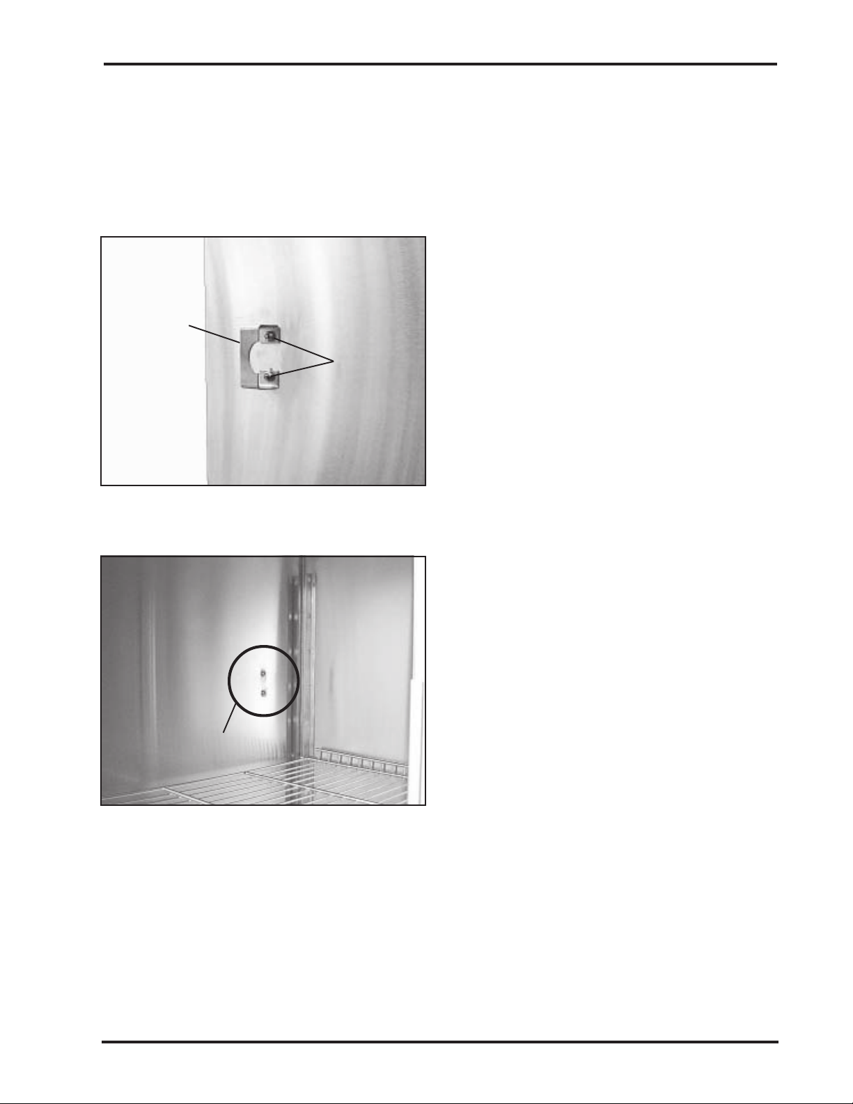
Handle Catch
P/N 616380 -
(Only on Case Carts
with External Handles)
Handle
Catch
Overview
All size case carts with external handles, 33 in., 48 in., and
63 in., have these handle catches.
Tools Required
3/8 in. wrench
Phillips screwdriver
Procedure
Note: If you do not remove the case cart door,
it will require two people to perform this
procedure due to the difficulty of reaching the
mounting nuts and screws at the same time.
Handle
Catch
Mounting
Nuts
1. Optional: Remove the case cart door.
(Refer to Note above.) Refer to
Removing and Installing a Case Cart
Door - Removal, Steps 1 through 3 on
Page 21. Observe the Cautions shown
in the procedure.
Figure 30. Handle Catch on Left Side of
Case Cart
Handle Catch
Mounting
Screws
Figure 31. Handle Catch Mounting
Screws Inside Case Cart
2. With a 3/8 in. wrench and a Phillips
screwdriver, remove the two mounting
screws/nuts on the handle catch
(Figures 30 and 31), and lift off the catch.
3. Mount the new latch handle to the case
cart with the screws/nuts removed above.
4. If you removed it, replace the door.
Refer to Removing and Installing a
Case Cart Door - Installation, Steps 1
through 3 on Page 21.
5. Try latching and unlatching the door
several times to make sure it works.
Form No. 702730 Rev. A November, 2006 25
Page 32
Chapter 4 - Repairs and Replacements
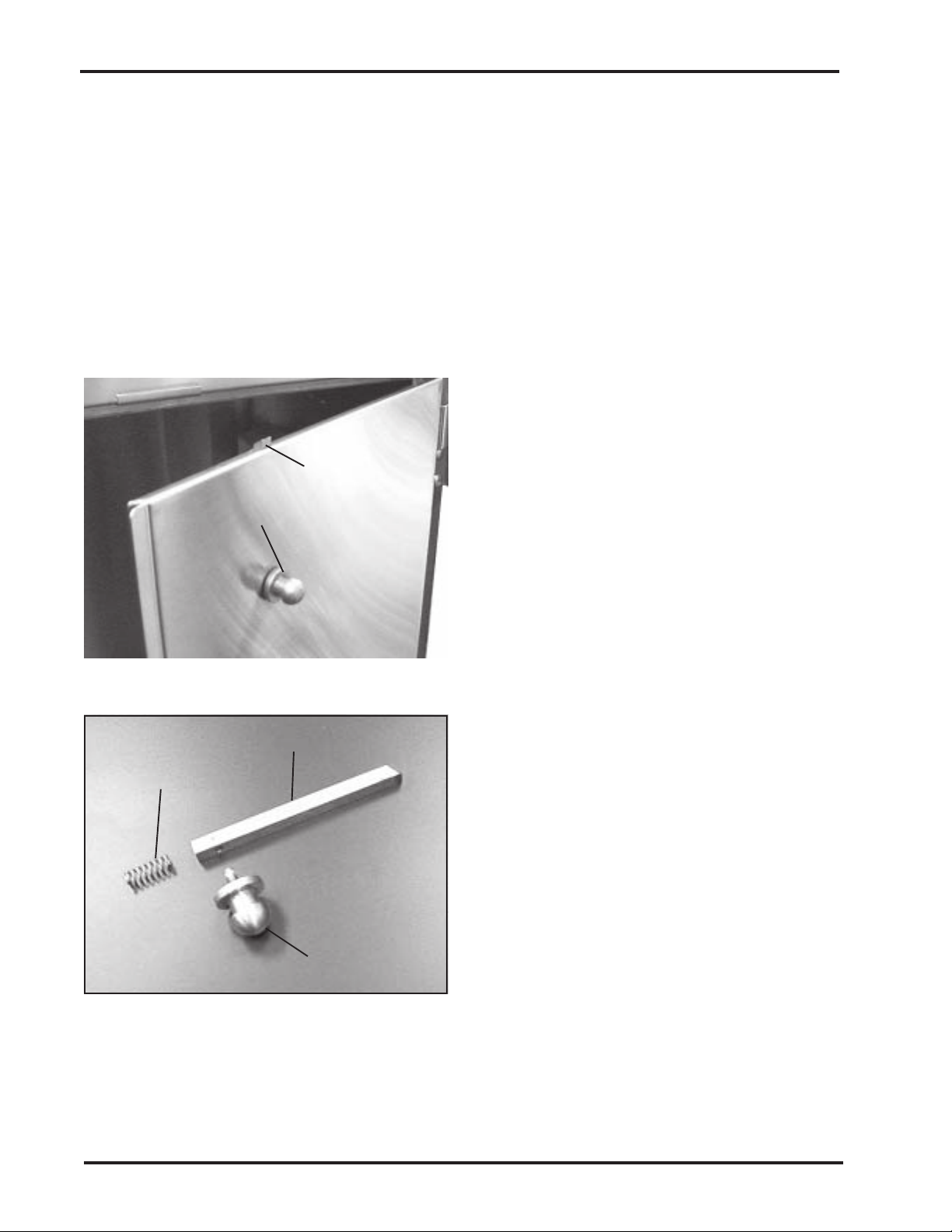
Knob Handle
P/N 202499
Latch Bolt
P/N 751549
Latch Bolt Spring
P/N 852406
Latch Bolt -
Knob Handle
Bevelled side
faces inside of
Overview
The knob handle, latch bolt, and latch bolt spring are closely
related parts. The knob handle can be replaced by itself.
Replacing the latch bolt requires removal of the knob handle.
Replacing the latch bolt spring requires removal of the latch bolt.
Tool Required
Pliers
Procedure
CAUTION: When using the pliers to loosen or tighten
the knob handle, try not to scratch or mar the handle.
1. With a pliers, unscrew the knob handle
from the door (Figure 32). If not
replacing the bolt or spring, proceed to
Step 7.
2. Note the position of the angled end of
the latch bolt. Grasp the bolt and pull it
cabinet
out of the door. If not replacing the
spring, proceed to Step 6.
Vertical Latch shown - horizontal
latch is identical.
Figure 32. Knob Handle and Latch Bolt
Latch Bolt
Latch Bolt
Spring
Knob Handle
Figure 33. Latch Parts
3. If replacing the spring, remove the door
from the case cart. Refer to Removing
and Installing a Case Cart Door Removal, Steps 1 through 3 on Page 21.
Observe the Cautions shown in the
procedure.
4. Hold the door so that the hole from
which the latch bolt was removed is
down, and allow the spring to fall out
(Figure 33).
5. Hold the door so that the hole from
which the latch bolt was removed is up,
and drop the new spring into the hole.
6. Insert the new or existing latch bolt (as
appropriate) into the hole. Make sure
the bevelled side faces the inside of the
cabinet.
26
SSCI - Suburban Surgical Company, Inc.
Page 33
Owner’s Manual - Tote-Al Case Carts - Single-door Models
7. Screw the new or existing knob handle (as appropriate)
into the latch bolt and tighten with a pliers.
8. If the door was removed from the case cart reinstall it
now. Refer to Removing and Installing a Case Cart
Door - Installation, Steps 1 through 3 on Page 21.
Bumper (Complete
with Vinyl Insert)
Recessed Handle Models -
P/N 203072
External Handle Models -
P/N 203072E
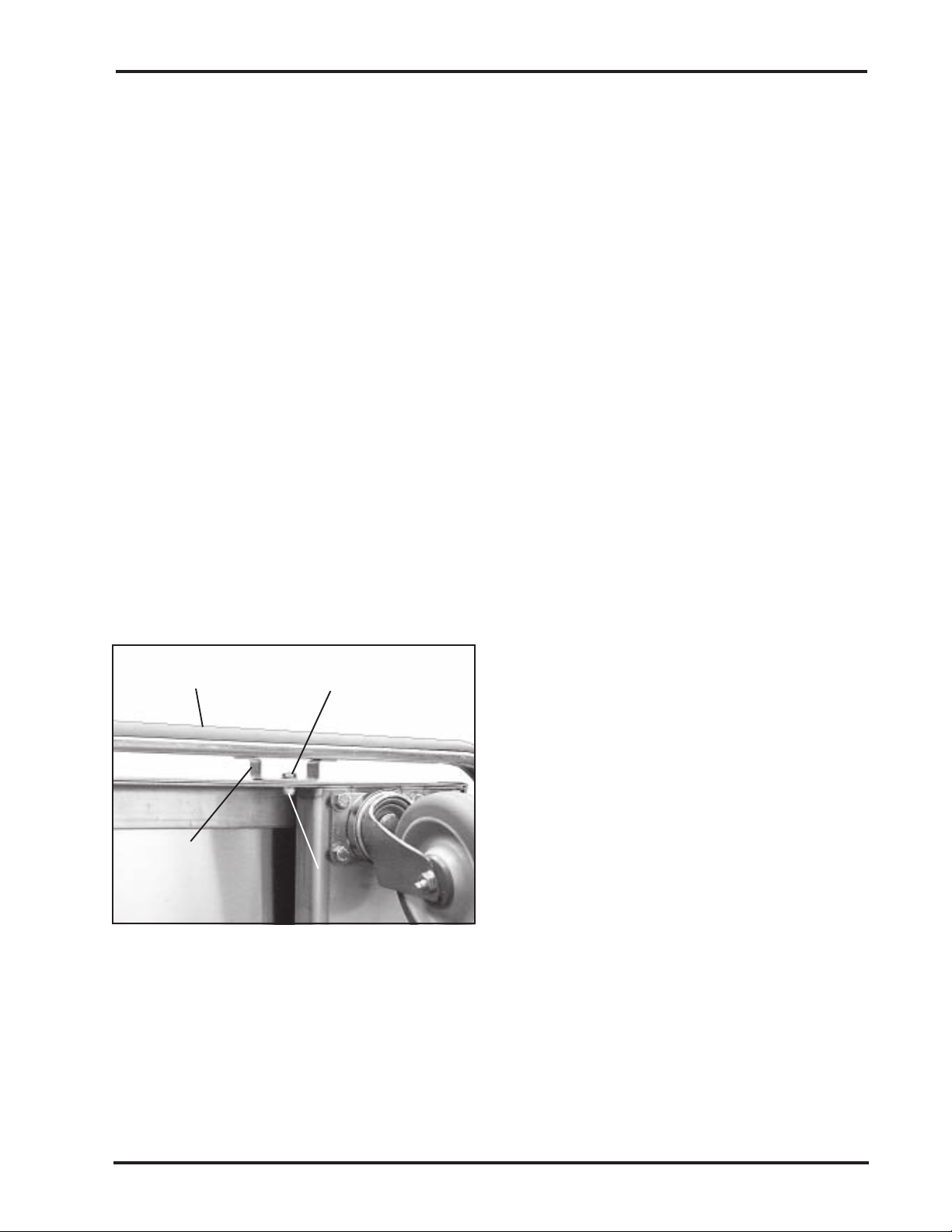
Bumper
Machine Screw
Overview
This is the complete bumper assembly including the vinyl
insert. All single-door bumper assemblies are the same except
that the bumpers for the case carts with extended handles are
longer to compensate for the greater cart length resulting from
the presence of the external handles.
Tools Required
Two 7/16 in. wrenches
Procedure
CAUTION: The case cart is heavy. We recommend
that tilting it over be done by at least two people.
1. Tilt the case cart over on one side, and block up the
lower end so that the bumper is off the floor.
2. With two 7/16 in. wrenches remove the
machine screws and locknuts from all
eight bumper bracket positions
(Figure 34).
3. Remove the old bumper from the case
cart.
4. Place the new bumper in place on the
Bumper
Bracket
(8)
Locknut
5. Using the machine screws and locknuts
cart.
removed above, mount the new bumper
Figure 34. Bumper, Bracket, and
to the cart.
Mounting Hardware
6. Remove the block from under the case
cart, and return the cart to the upright
position.
Form No. 702730 Rev. A November, 2006 27
Page 34
Chapter 4 - Repairs and Replacements
Adjustable Shelf
Wire - P/N 220300-00
Solid - P/N 220310-00
Perforated - P/N 220320-00
Roll-out Shelf
Wire - P/N 220330-00
Solid - P/N 220340-00
Perforated - P/N 220350-00
Roll-out Shelf Track
Left - P/N 210007
Right - P/N 210008
Overview
All adjustable shelves, wire, solid, and perforated, are removed
and installed in the same way.
Procedure
Refer to Adjustable Shelves on Page 16, and use the procedure
given there for moving a shelf.
Overview
All roll-out shelves, wire, solid, and perforated, are removed
and installed in the same way.
Procedure
Refer to Using Roll-out Shelves - Removing and Replacing
Roll-out Shelves on Page 14, and use the procedure given there.
Overview
Left and right roll-out shelf tracks are removed and installed
the same way.
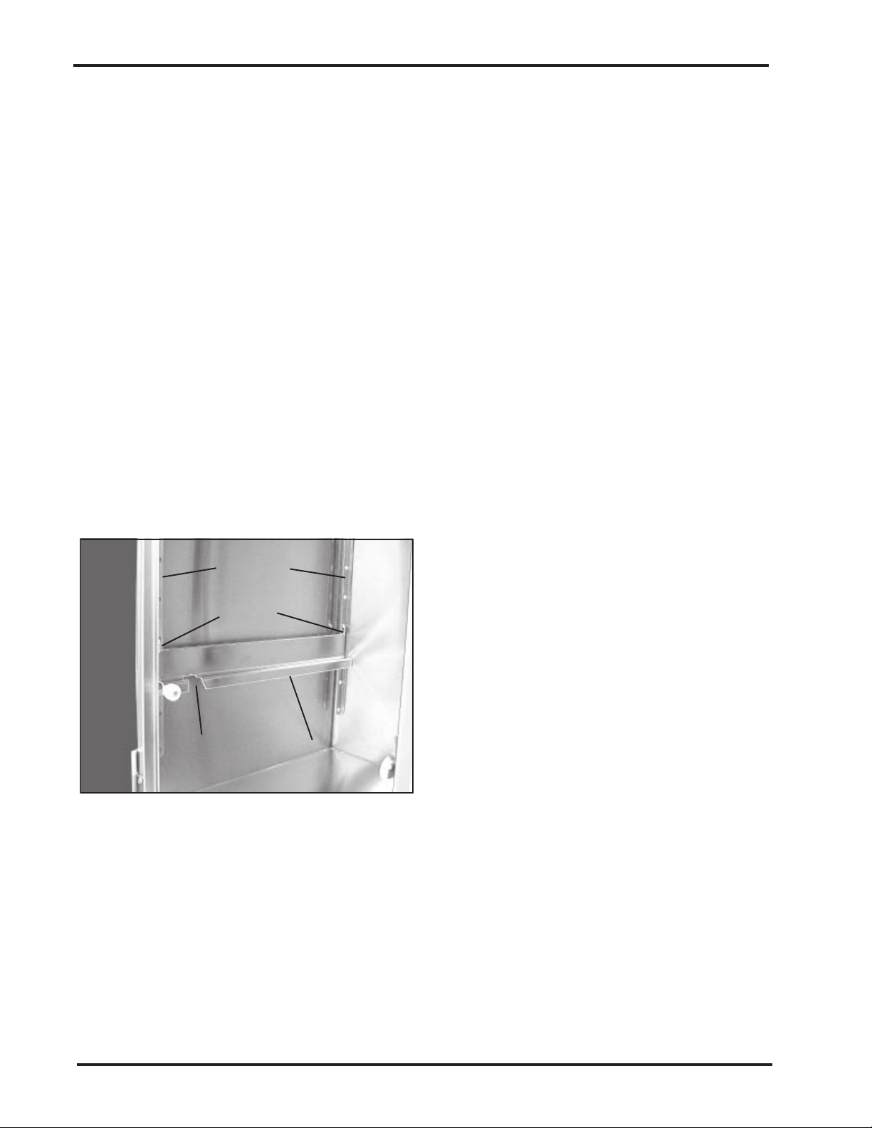
Vertical
Brackets
Hooks
Gap
Roll-out Shelf
Track
Figure 35. Roll-out Shelf Track and
Vertical Brackets
Procedure
1. Remove the shelf from the cabinet (refer
to Removing and Replacing Roll-out
Shelves - Removal, Steps 1 through 5,
starting on Page 14).
2. Lift up on the roll-out shelf track and
unhook it from the front and rear
vertical brackets (Figure 35).
3. Hook the new track to the vertical
brackets.
4. Replace the shelf onto the shelf tracks
(refer to Removing and Replacing
Roll-out Shelves - Replacement, Steps 1
through 8 on Page 15). Note: Make
sure the shelf is level side-to-side and
front-to-rear.
28
SSCI - Suburban Surgical Company, Inc.
Page 35
Owner’s Manual - Tote-Al Case Carts - Single-door Models
Rollers for Roll-out
Shelves and Tracks
Overview
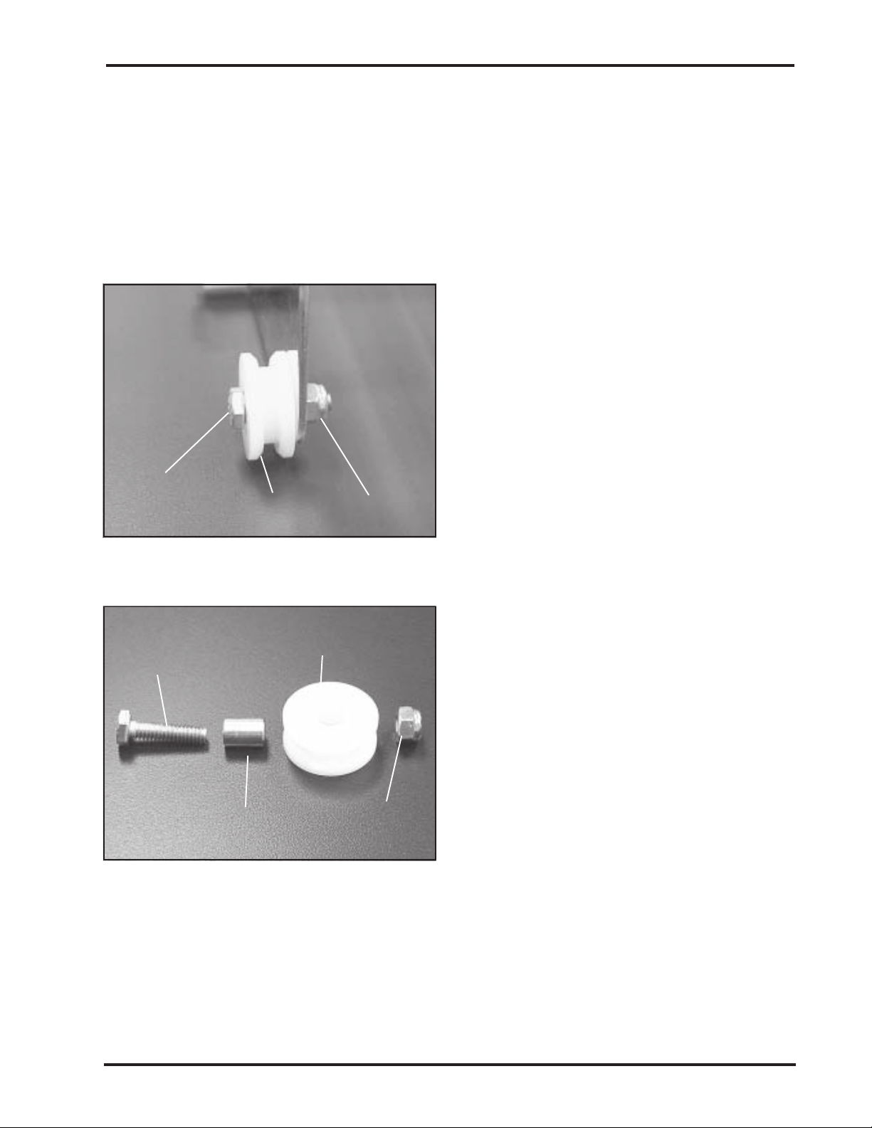
Each roll-out shelf track has one large, grooved roller. Each
roll-out shelf has two large, grooved rollers, and four small,
Large, Grooved Rollers -
P/N 753332
Small, Smooth Rollers -
smooth rollers. All large, grooved rollers are the same, and all
small, smooth rollers are the same. All rollers are removed and
replaced in the same way.
P/N 753333
Tools Required
Two 7/16 in. wrenches
Machine
Screw
Roller Locknut
Figure 36. Roller Machine Screw and
Locknut
Machine
Screw
Roller
Procedure
1. Remove the shelf from the cabinet (refer
to Removing and Replacing Roll-out
Shelves - Removal, Steps 1 through 5,
starting on Page 14).
2. If replacing a roller on the roll-out shelf
track, lift up on the track and unhook it
from the front and rear vertical brackets
(Figure 35).
3. Locate the roller you wish to replace.
With two 7/16 in. wrenches, remove the
machine screw and locknut that hold the
roller in place, and remove the roller
from the shelf or track, as appropriate
(Figure 34).
4. Remove the sleeve from the old roller
and discard the roller.
5. Install the sleeve into the new roller
(Figure 37).
6. Mount the new roller/sleeve and secure
it with the machine screw/locknut
Sleeve
Figure 37. Roller and Sleeve
Locknut
removed earlier.
7. If it was removed, hook the track to the
vertical brackets.
8. Replace the shelf onto the shelf tracks (refer to Removing
and Replacing Roll-out Shelves - Replacement, Steps 1
through 8 on Page 15).
Form No. 702730 Rev. A November, 2006 29
Page 36

Chapter 4 - Repairs and Replacements
Care of Wheel/Caster
Assemblies
Overview
Inspection
The wheel/caster assemblies on the case carts were selected by
SSCI for high durability and long life. Two of the casters on
each transport cage are equipped with swivel locks. Users are
responsible for the proper operation, care, and maintenance of
their equipment. Equipment can become damaged and unsafe if
abused or subjected to improper demands. If your equipment is
regularly maintained and never abused, you will get the
maximum safety and service from your casters.
Never overload the case cart.
Do not drop heavy loads on the case cart.
Do not use the transport cart at high speeds.
The above conditions can create severe impact and shock loads
on your case cart and may result in caster, wheel, or equipment
failure.
Equipment Frames and Fasteners
Periodically examine the case cart and check the following:
Look for broken welds on the case cart.
Tighten any loose nuts and bolts.
Look for distortion of the cart caused by overload and
impacts. Distorted carts can lead to wheel failure by
placing disproportionate loads on one or two casters.
Make sure the casters are not bent and the mounting
bolts are securely fastened.
Casters
Check the swivel assembly on each caster for excessive play
due to wear. If the swivel is loose, replace the caster. If the
swivel does not turn freely, check for corrosion or dirt binding
the raceways. Make sure the swivel nut and wheel axle nuts are
tight. If a caster is not operating properly, disassemble, clean,
and lubricate it. If this does not fix the problem, replace the
assembly (refer to Caster on Page 23).
Wheels
Check each wheel for excessive or uneven tread wear, or badly
worn or “chunked out” rubber tires. Such conditions can cause
erratic steering, bumping, load shifting, and damage to floors.
If a wheel binds and no longer rolls freely, or if flat spots
appear on the tire, carefully inspect the wheel/caster assembly
for damage or accumulated foreign matter (dirt, string, animal
hair, etc.). If necessary, replace the assembly (refer to Caster on
Page 23).
30
SSCI - Suburban Surgical Company, Inc.
Page 37
Owner’s Manual - Tote-Al Case Carts - Single-door Models
Swivel Locks
Check swivel locks for proper operation. Apply lock one at a
time and attempt to move the equipment to make sure that each
lock is not slipping or loose.
If locks slip due to worn or damaged wheels, replace the
wheels immediately and retest the brakes. If the lock
mechanism itself is not operating properly, repair or replace it.
Before returning the equipment to use, always retest the locks.
Lubrication
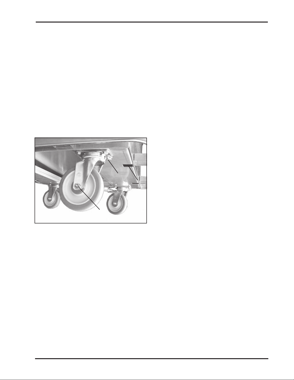
Wheel Bearing
Grease Fitting
Figure 28. Wheel/Caster Assembly
Grease Fittings
Caster and wheel lubrication is essential. The lubrication
schedule depends on your specific application. Normal
conditions warrant lubrication every six months, however, for
wet or corrosive applications, monthly lubrication may be
necessary.
Swivel Bearing
Grease Fitting
Lubrication may also be required after each
piece of equipment is washed. Special hightemperature, water-resistant lubricants may be
used for these applications. If necessary, SSCI
can provide stainless steel casters that require
less maintenance.
The wheel/caster assemblies have two grease
fittings (Figure 28), one for the wheel and one
for the swivel. Use enough grease to fill the
bearing, but not so much that it oozes out of the
grease seal. After applying the grease, turn the
wheel or swivel several times in both directions
to distribute the grease evenly.
Recommended
Lubricants
Power Towed
Operation
Form No. 702730 Rev. A November, 2006 31
SSCI recommends that you use either of the following greases
when lubricating your case cart casters:
Citgo EP-1
Exxon Beacon EP 1
Based on available information, these products are not
expected to produce adverse effects on health when used for
the intended application and the recommendations provided in
the Material Safety Data Sheets (MSDS) are followed.
MSDS’s are available via the Internet.
Power drawn equipment such as in a tow line or mechanically
moved by conveyor will require casters, wheels, and bearings
specifically designed for this use. Please consult the factory for
caster recommendations of each specific towing or power
drawn equipment application.
Page 38

Chapter 4 - Repairs and Replacements
Comments:
32
SSCI - Suburban Surgical Company, Inc.
Page 39

Inside back cover
This page left blank intentionally
Page 40

For more information on SSCI’s fine line of products
and accessories, talk to your SSCI sales representative.
SSCI
Suburban Surgical Company, Inc.
275 Twelfth Street Wheeling, IL 60090
Phone: (847) 537-9320 Fax: (847) 537-9061
Toll Free: (800) 323-7366 Web: www.suburbansurgical.com
Form No. 702730 Rev. A 11/06
 Loading...