

Page 1

C100_RHD_00_Foreword.p65 2006-05-16, ¿ÀÈÄ 8:271
Page 2

C100_RHD_00_Foreword.p65 2006-05-16, ¿ÀÈÄ 8:272
Page 3
FOREWORD
This manual has been prepared to acquaint you with the operation and maintenance
of your new ACTYON and to provide important safety information. We urge you to
read it carefully and follow the recommendations to help assure the most enjoyable,
safe, and trouble-free operation of your vehicle.
When it comes to service, remember that your SSANGYONG dealer knows your
vehicle best and is interested in your complete satisfaction.
We would like to take this opportunity to thank you for choosing ACTYON and
assure you of our continuing interest in your motoring pleasure and satisfaction.
This manual should be considered as a permanent part of your vehicle, and must
remain with the vehicle at the time of resale.
PYUNGTAEK, KOREA
C100_RHD_00_Foreword.p65 2006-05-16, ¿ÀÈÄ 8:273
Page 4

IMPORTANT NOTICE
Please read this manual and follow the instructions carefully.
Signal words such as “WARNING”, “CAUTION” and “NOTE”
have special meanings.
WARNING
WARNING
WARNING indicates a potentially hazardous situation which, if not
avoided, could result in death or serious injury.
CAUTION
CAUTION
CAUTION indicates a potentially hazardous situation which, if not
avoided, may result in minor or moderate injury or property damage.
NOTE
All information, illustrations and specifications in this manual
are based on the latest product information available at the
time of publication.
Ssangyong reserves the right to change specifications or design at any time without notice and without incurring any obligation whatsoever.
This vehicle may not comply with the standards or regulations of other countries. Before attempting to register this vehicle in any other country, check all applicable regulations and
make any necessary modifications.
This manual describes options and trim levels available at
the time of printing, and therefore, some of the items covered
may not apply to your vehicle. If any doubt exists about any of
the options or trim levels, please do not hesitate to contact
your Ssangyong Distributor for information on the latest
specifications.
* : This asterisk in this manual signifies that an item of equip-
ment is not included in all vehicles (model variants, engine options, models specific to one country, optional
equipment, etc.).
NOTE
NOTE indicates information to assist maintenance and instructions.
C100_RHD_00_Foreword.p65 2006-05-16, ¿ÀÈÄ 8:274
We would like to point out that non Ssangyong Genuine parts
and accessories have not been examined and approved by
Ssangyong, and in spite of continuous market product
monitoring, we cannot certify the suitability nor the safety of
such products whether they are installed or intended for fitment
in our vehicles. Ssangyong is not liable for any damage caused
by the use of non Ssangyong Genuine parts and accessories.
Page 5
TABLE OF CONTENTS
0. General .................................................. Section 0
1. Safety Precautions ................................. Section 1
0
1
2. Ignition Key, Remote Control Key ........ Section 2
3. Opening and Closing .............................. Section 3
4. Interior Switches ..................................... Section 4
5. Instrument Cluster .................................. Section 5
6. Transmission and Brake System ........... Section 6
7. Seats ........................................................ Section 7
8. Seat Belt and Air Bag............................. Section 8
9. Ventilation, Heating, and
Air Conditioning ...................................... Section 9
10. Turbocharger System ........................... Section 10
11. Convenience Devices ............................Section 11
12. In Case of Emergency .......................... Section 12
13. Service and Maintenance .................... Section 13
14. Lamps .................................................... Section 14
15. Vehicle Care.......................................... Section 15
16. Index ...................................................... Section 16
2
3
4
5
6
7
8
9
10
11
12
13
14
15
16
C100_RHD_00_Foreword.p65 2006-05-16, ¿ÀÈÄ 8:275
Page 6

C100_RHD_00_Foreword.p65 2006-05-16, ¿ÀÈÄ 8:276
Page 7

0
General
TABLE OF CONTENTS
Recommended Fluids and Lubricants ....... 0-2
Dimensions................................................... 0-3
Specifications .............................................. 0-4
Vehicle Identification .................................. 0-7
0
1
2
3
4
5
6
7
8
9
10
11
12
13
14
15
C100_RHD_00-General.p65 2006-05-16, ¿ÀÈÄ 8:271
16
Page 8
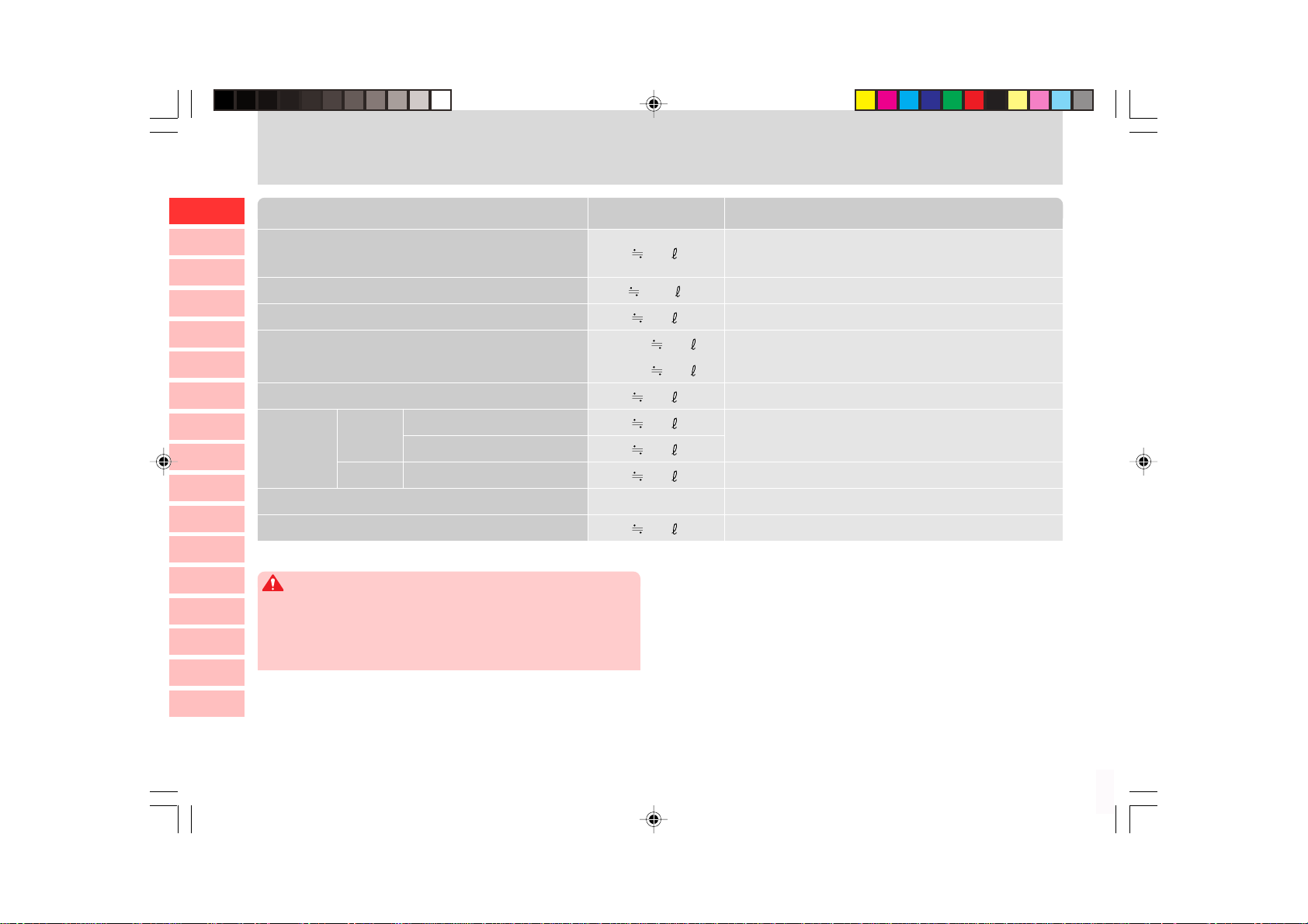
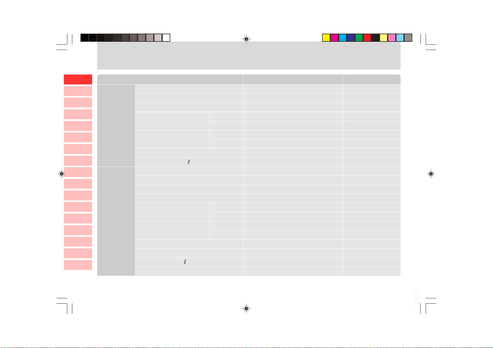
RECOMMENDED FLUIDS AND LUBRICANTS
10
11
12
13
14
15
0
1
Engine Oil
Descriptions SpecificationsCapacity
2
Engine Coolant
3
Automatic Transmission Fluid
4
Manual Transmission Fluid
5
Transfer Case Fluid
6
Axle Oil
7
Front
8
Rear
9
Brake / Clutch Fluid
Power Steering Fluid
WARNING
• Use only Ssangyong recommended fluids and lubricants.
• Do not mix any different types or brands of oils or fluids. This may
cause damages.
• Keep the specified levels when adding or replacing the fluids.
Automatic Transmission
Manual Transmission
Solid Axle Suspension
7.5
11.5
9.5
4WD: 3.6
2WD: 3.4
1.4
1.4
1.4
1.9
As required
1.0
Ssangyong genuine engine oil
(Approved by MB Sheet 229.1 or 229.3)
Ssangyong genuine coolant
Ssangyong genuine oil (CASTROL TQ 95)
Ssangyong genuine oil (ATF DEXRON II)
Ssangyong genuine oil (ATF DEXRON III)
Ssangyong genuine oil (SAE 80W/90, API GL-5)
Ssangyong genuine oil (SAE 80W/90, API GL-5)
Ssangyong genuine oil (DOT4)
Ssangyong genuine oil (ATF DEXRON II or III)
16
0-2
C100_RHD_00-General.p65 2006-05-16, ¿ÀÈÄ 8:272
Page 9
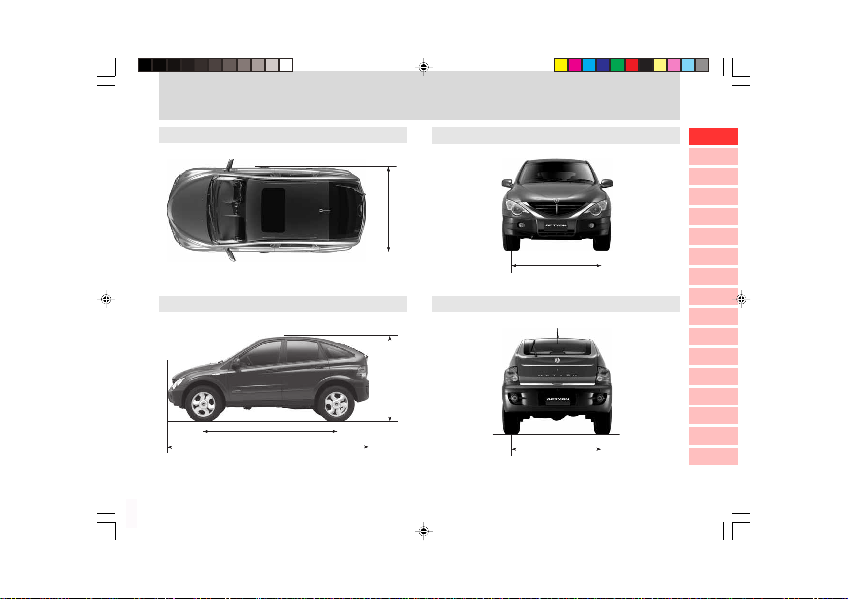
DIMENSIONS
Unit: mm
Top View
Side View
1880
1735
Front View
1570
Rear View
0
1
2
3
4
5
6
7
8
9
10
11
12
13
14
4455
* ( ) : Optional
C100_RHD_00-General.p65 2006-05-16, ¿ÀÈÄ 8:273
2740
1570
15
16
0-3
Page 10
SPECIFICATIONS (I)
* ( ) Optional
10
11
12
13
14
15
16
0
General
1
2
3
4
5
6
7
Engine
8
9
Descriptions
Overall length (mm)
Overall width (mm)
Overall height (mm)
Gross vehicle weight (kg) A/T
M/T
Curb vehicle weight (kg) A/T
M/T
Fuel
Fuel tank capacity (
Engine name
Numbers of cylinders/Compression ratio
Total displacement (cc)
Camshaft arrangement
Max. power A/T
Max. torque A/T
Idle speed
Cooling system
Coolant capacity (
Lubrication type
)
M/T
M/T
)
2WD: 1,865 / 4WD: 1,974
2WD: 1,843 / 4WD: 1,951
310 Nm / 1,800 ~ 2,750 rpm
310 Nm / 1,800 ~ 2,750 rpm
Water- cooled / forced circulation
Gear pump, forced circulation
Diesel
4,455
1,880
1,735
2,520
2,520
Diesel
75
D20DT
4 / 18:1
1,998
DOHC
141 PS / 4,000 rpm
141 PS / 4,000 rpm
780 ± 50 rpm
11.5
Remarks
0-4
C100_RHD_00-General.p65 2006-05-16, ¿ÀÈÄ 8:274
Page 11

SPECIFICATIONS (II)
Engine
Manual
Transmission
Automatic
Transmission
Transfer
Case
Descriptions
Max. oil capacity ( ) (when shipping)
Turbocharger and cooling type
Operating type
Gear ratio 1st
2nd
3rd
4th
5th
Reverse
Model
Operating type
Gear ratio 1st
2nd
3rd
4th
Reverse
Model
Type
Gear ratio High (4H)
Diesel
8.2
Turbocharger, air-cooled
Semi- Remote control, floor change type
4.315
2.475
1.536
1.000
0.807
3.919
Electronic, 4-speed
Floor change type
2.742
1.508
1.000
0.708
2.428
2WD, Part-time
Planetary gear type
1.000 : 1
Remarks
0
1
2
3
4
5
6
7
8
9
10
11
12
13
14
15
C100_RHD_00-General.p65 2006-05-16, ¿ÀÈÄ 8:275
16
0-5
Page 12

SPECIFICATIONS (III)
* ( ) Optional
10
11
12
13
14
15
16
0
Clutch (M/T)
1
2
Power Steering
3
4
Front Axle
5
6
Rear Axle
7
Brake
8
9
Suspension
Air Conditioner
Electrical
Descriptions
Operating type
Disc type
Type
Steering angle Inner
Outer
Drive shaft type
Axle housing type
Drive shaft type Solid axle suspension
Axle housing type
Master cylinder type
Booster type
Brake type Front wheels
Rear wheels
Parking brake
Front suspension
Rear suspension Solid axle suspension
Refrigerant (capacity)
Battery type / Capacity (V-AH)
Starter capacity (V-kW)
Alternator capacity (V-A)
Diesel
Hydraulic type
Dry single diaphragm type
Rack and pinion
35.7°
32.1°
Ball joint type
Build-up type
Semi-floating type
Build-up type
Tandem type
Vacuum assisted booster type
Disc type
Drum (disc)
Cable type (internal expansion)
Wishbone + coil spring
5-link + coil spring
R-134a (650 ± 30g)
MF / 12 - 90
12 - 2.2
12 - 115
Remarks
0-6
C100_RHD_00-General.p65 2006-05-16, ¿ÀÈÄ 8:276
Page 13
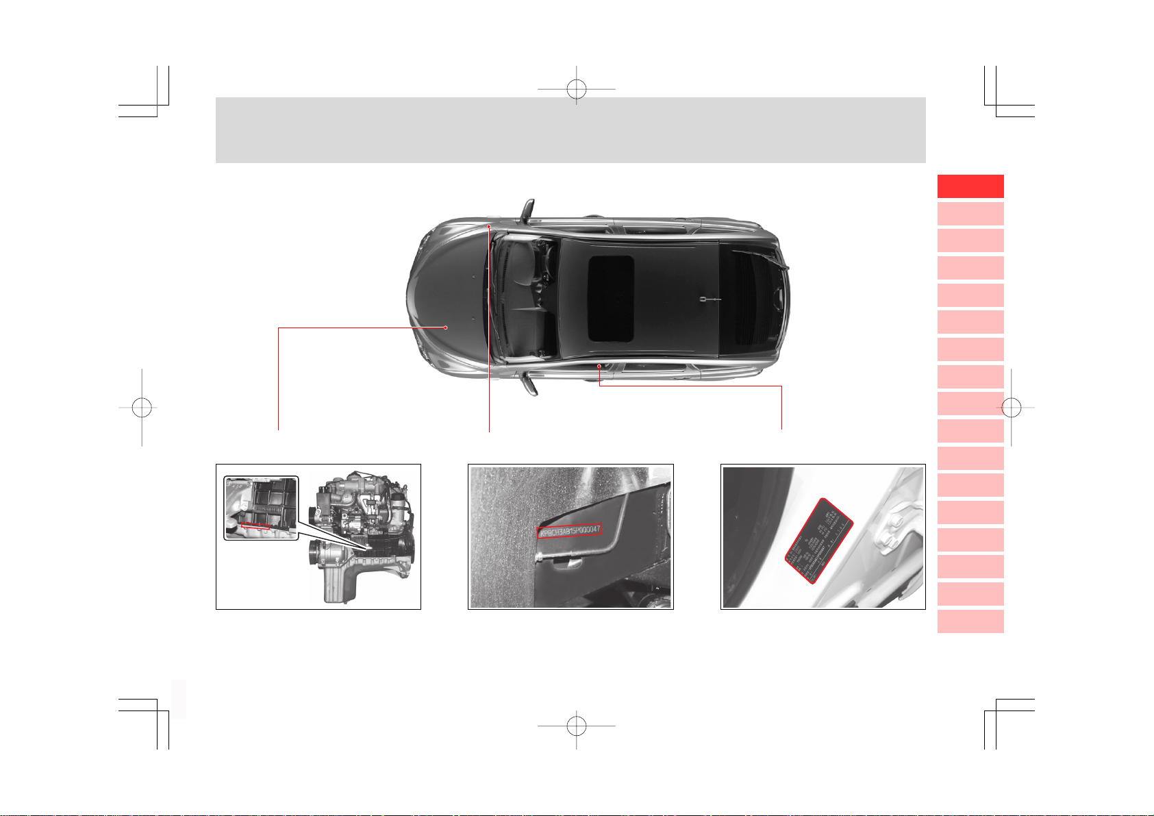
VEHICLE IDENTIFICATION
1. Engine Number
2. Chassis Number
0
1
2
3
4
5
6
7
8
9
3. Certification Label
10
11
12
13
The engine number is stamped on
the lower area of cylinder block behind the Intake manifold.
C100_RHD_00-General.p65 2006-05-19, ¿ÀÈÄ 2:33Page 7 Adobe PageMaker 6.5K/Win
The chassis number is stamped on
the frame behind the front right tire.
The certification label is located on
the passenger’s door sill.
14
15
16
0-7
Page 14

MEMO
.....................................................................................................................................................................................................................................................................................................................................................................................................................................................................................
.....................................................................................................................................................................................................................................................................................................................................................................................................................................................................................
.....................................................................................................................................................................................................................................................................................................................................................................................................................................................................................
.....................................................................................................................................................................................................................................................................................................................................................................................................................................................................................
.....................................................................................................................................................................................................................................................................................................................................................................................................................................................................................
.....................................................................................................................................................................................................................................................................................................................................................................................................................................................................................
.....................................................................................................................................................................................................................................................................................................................................................................................................................................................................................
.....................................................................................................................................................................................................................................................................................................................................................................................................................................................................................
.....................................................................................................................................................................................................................................................................................................................................................................................................................................................................................
.....................................................................................................................................................................................................................................................................................................................................................................................................................................................................................
.....................................................................................................................................................................................................................................................................................................................................................................................................................................................................................
.....................................................................................................................................................................................................................................................................................................................................................................................................................................................................................
.....................................................................................................................................................................................................................................................................................................................................................................................................................................................................................
.....................................................................................................................................................................................................................................................................................................................................................................................................................................................................................
.....................................................................................................................................................................................................................................................................................................................................................................................................................................................................................
C100_RHD_00-General.p65 2006-05-16, ¿ÀÈÄ 8:278
Page 15

0
Safety Precautions
TABLE OF CONTENTS
Checks Before Starting a Journey ............. 1-2
Starting the Engine and Driving off the
Vehicle ......................................................... 1-3
Safety Precautions ...................................... 1-5
Direct Injection Type Diesel Engine ......... 1-10
1
1
2
3
4
5
6
7
8
9
10
11
12
13
14
15
C100_RHD_01-Safety Precautions.p65 2006-05-16, ¿ÀÈÄ 8:271
16
Page 16
CHECKS BEFORE STARTING A JOURNEY
10
11
12
13
14
0
CHECKS BEFORE STARTING A JOURNEY
1
2
3
4
5
6
7
8
9
CHECK THE VEHICLE OUTSIDE
1. Check the tire inflation and wear.
2. Check the engine oil and other fluid/oil levels in the
engine compartment.
3. Clean the windshield and rear glasses, side mirrors,
and room mirrors.
4. Make sure that the engine hood and tailgate are properly closed.
5. Make sure that there are no obstacles in the danger
area around the vehicle.
CHECK THE VEHICLE INSIDE
1. Make sure that all doors including the tailgate are properly closed.
2. Adjust the driver’s seat for comfortable driving.
3. Adjust the outside and inside rear view mirrors.
4. Fasten the seat belts and be sure that all other occupants have fastened theirs properly.
5. Check operation of the parking brake.
6. Check that all appropriate warning lights are operating when turning the ignition key to the “ON” position.
7. Check the operations of the clutch pedal, accelerator
pedal, and brake pedal.
8. Make sure that there are no obstacles in the danger
area around the vehicle.
15
16
1-2
C100_RHD_01-Safety Precautions.p65 2006-05-16, ¿ÀÈÄ 8:272
SAFETY PRECAUTIONS
Page 17
STARTING THE ENGINE AND DRIVING OFF THE VEHICLE
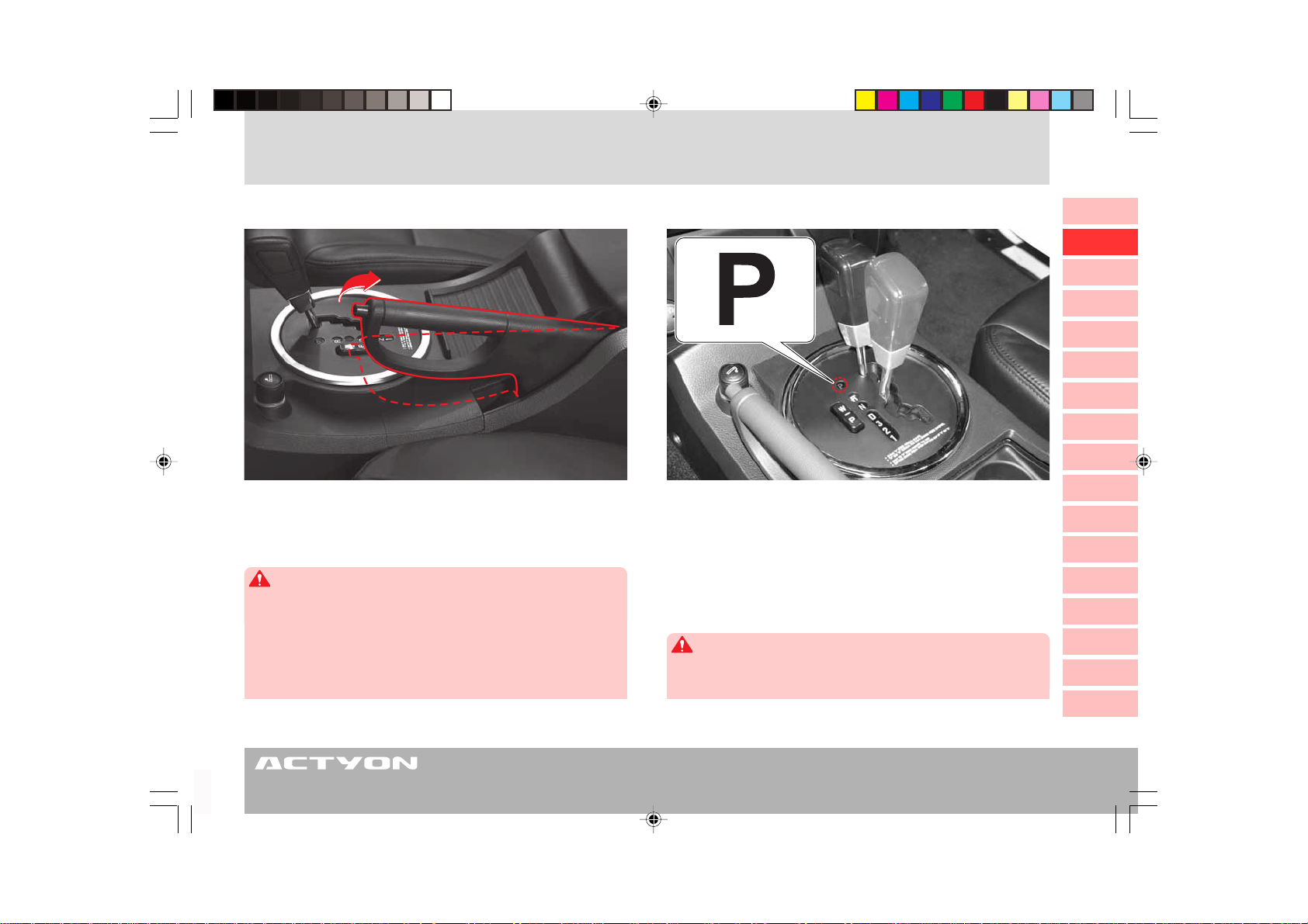
1. Apply the parking brake.
2. Make sure that there are no persons or obstacles in the
dangerous area around the vehicle.
CAUTION
The engine with an automatic transmission equipped vehicle can
be started only when the selector lever is at the “P” or “N”
position. The engine with a manual transmission equipped in ve-
hicle can be started only when the clutch pedal is fully depressed.
Do not turn the ignition key to the
engine is running. It could result in serious start motor damage.
“START” position while the
3. • Automatic transmission equipped vehicle
Move the selector lever to the
the brake pedal.
• Manual transmission equipped vehicle
Move the gearshift lever to the Neutral position and fully
depress the brake pedal and the clutch pedal.
WARNING
Depress the brake pedal when the selector lever is at the “P”
position. Never depress the accelerator pedal.
“P” position and depress
0
1
2
3
4
5
6
7
8
9
10
11
12
13
14
15
16
C100_RHD_01-Safety Precautions.p65 2006-05-16, ¿ÀÈÄ 8:273
SAFETY PRECAUTIONS
1-3
Page 18
0
1
2
3
4
5
6
7
8
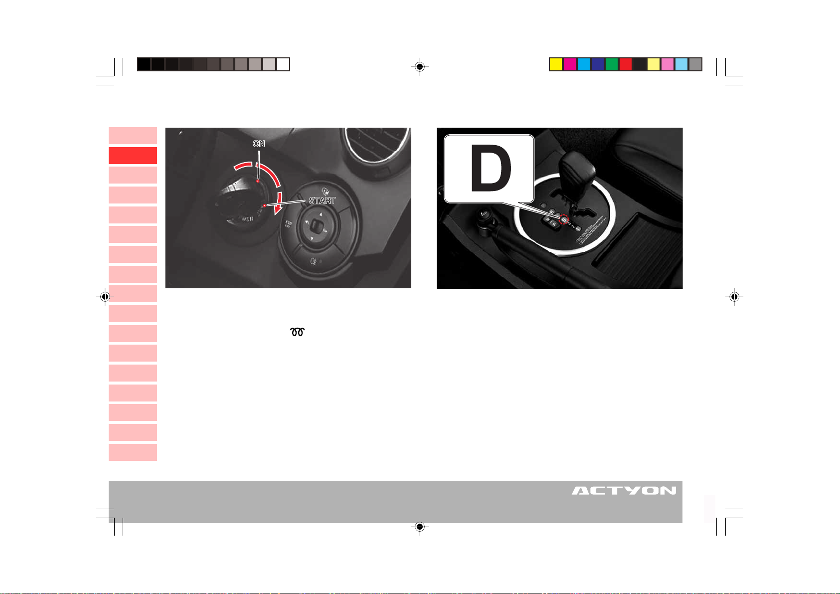
4. Insert the ignition key into the key cylinder and turn it to the
9
10
11
12
13
14
“ON” position without depressing the accelerator pedal. As
soon as the glow indicator ( ) goes out, turn the key to
“START” position to start the engine.
the
5. Release the key when the engine starts. If your vehicle is
equipped with a manual transmission and is engaged
at neutral (N), it is ok to release the clutch pedal when
the engine runs.
6. Warm up the engine in idling speed. Do not warm up the
engine excessively.
15
16
7. Make sure that there are no persons or obstacles in the
danger area around the vehicle.
8. Release the parking brake.
9. • Automatic transmission equipped vehicle
Keep the brake pedal depressed and shift into the
position. Make sure that the position indicators of “D”
are coming on. Slowly release the brake pedal to begin
moving.
• Manual transmission equipped vehicle
Keep the brake pedal and clutch pedal depressed and
shift into the
gradually depress the accelerator while slowly releasing
the clutch to begin moving.
“1” position. Release the brake pedal and
“D”
1-4
C100_RHD_01-Safety Precautions.p65 2006-05-16, ¿ÀÈÄ 8:274
SAFETY PRECAUTIONS
Page 19
SAFETY PRECAUTIONS
SAFETY PRECAUTIONS (I)
Ignition Key/Remote Control Key
1. Never use any duplicated key not provided by
Ssangyong. It may cause a fire due to an overload in
the electric circuit.
2. If you lose your keys, you have to replace the whole key
set to prevent from theft.
3. Avoid shock to the transmitter in the remote control key
and do not get it wet.
4. Only use the batteries with the same specifications to
replace the discharged battery. Do not reverse the
polarity.
Turbocharger System
If the oil supply for the bearing assembly of the fast rotating turbo charger stops, the stop will cause the turbocharger to seize. Therefore, the following cares are necessary to prevent the seizure.
1. After starting the engine, let it run for approx. 2 minutes
at idle speed (Avoid acceleration or driving off the
vehicle).
2. After changing the engine oil and oil filter, start the engine and let it run for approx. 2 minutes at idle speed
(Avoid acceleration or driving off the vehicle).
3. Do not stop the engine immediately after coming back
from high load driving (such as high speed driving or
driving on long slope). Let the engine run for approx. 2
minutes at idle speed to cool it down.
Air Bag
1. Never impact the air bag installations by hands or tools.
2. The air bag system serves as a supplement to the
seat belt. Make sure that you and your passengers
always fasten the seat belts properly even if the air
bags are installed in the vehicle.
3. Do not place any objects on the air bag inflation
location. You may be injured by those objects during
deployment.
4. The air bag system should be inspected 10 years after installation regardless of its appearance and other
conditions.
5. Repairs to the air bag system should be done only
by a Ssangyong Dealer or Ssangyong Authorized Service Center.
6. Do not diagnose the circuit with a circuit tester. Do not
attempt to modify any air bag components including the
steering wheel, air bag mounting area, and harness.
7. Never install a child restraint in the front seat. The children on the restraint could be seriously injured by the
air bag in a collision.
8. The deployed air bag unit should be removed from
the vehicle and replaced with a new one.
9. When the air bag is deployed, the relevant components will be very hot, so do not touch them until they
have cooled down.
10. A person who is smaller than 140 cm should sit in
the rear.
0
1
2
3
4
5
6
7
8
9
10
11
12
13
14
15
16
C100_RHD_01-Safety Precautions.p65 2006-05-16, ¿ÀÈÄ 8:275
SAFETY PRECAUTIONS
1-5
Page 20
10
11
12
13
14
15
16
0
1
Hazardous Materials
Do not store any flammable items or disposable lighters
2
in the console box or other spaces. In hot weather, they
3
can explode and cause a fire.
4
Genuine Parts
Always use only Ssangyong genuine parts for
5
replacement. Ssangyong is not liable for any damage
caused by the use of non-Ssangyong genuine parts and
6
accessories.
SAFETY PRECAUTIONS (II)
7
Tire
8
1. Be sure to use the same size and type of tires from the
9
same manufacturer on all wheels. Otherwise, damage
can be caused to the powertrain.
2. Keep the specified tire inflation pressure.
3. Make sure that the spare tire is ready for use at any
time. After installing the spare tire on a wheel, do not
drive for a long distance. Instead, visit a nearby dealer
or tire shop to replace the spare tire with a regular tire
for driving.
4. Always check the tire surface for damage and uneven
wear before driving and replace it if needed.
5. Using tires of different specifications may cause high
fuel consumption, long stopping distance, vehicle body
vibration, heavy steering operation, and poor ABS
operation.
Power Window
1. When you operate the rear windows from the driver’s
seat while a child sits in the rear, make sure that no
body part of the child is between the window and the
window frame.
2. When carrying children in the rear seat, press the rear
door window lock switch to make the rear door
switches inoperative.
3. Make sure that all passengers have their body parts
such as hands inside the vehicle.
4. When closing the windows, be aware of safety conditions before operation.
Glass Care
1. Be careful not to damage the rear heated wire and diversity antenna when cleaning the rear glass.
2. Do not install any sunshield on the windshield glass
and rear glass. It may adversely affect the rear heated
wire and receiving sensitivity of the antenna.
3. The rain and automatic light sensors are installed on
the upper middle front of the windshield (if equipped).
If these sensors are contaminated or covered with various coating sprays, the automatic rain sensing wipers
and lights may not work properly.
1-6
C100_RHD_01-Safety Precautions.p65 2006-05-16, ¿ÀÈÄ 8:276
SAFETY PRECAUTIONS
Page 21
SAFETY PRECAUTIONS (III)
0
Child Restraint
When transporting infants or small children, an appropriate child restraint system should always be used. The child
restraint system should be appropriate for your child’s
WARNING
• Infants and small children should always be restrained in an
infant or child restraint.
• NEVER INSTALL A REAR-FACING CHILD RESTRAINT IN THE
FRONT SEAT WITH FRONT PASSENGER AIR BAG.
• A child in a rear-facing child restraint installed in the front seat
can be seriously injured if the front passenger air bag inflates.
Secure a rear-facing child restraint in the rear seat.
• A front-facing child restraint should be secured in the rear
seat whenever possible. If installed in the front passenger
seat, adjust the seat as far back as it will go.
• When installing a child restraint system, follow the instructions
provided by the manufacturer.
• When not in use, keep your child restraint system secured
with a seat belt or remove it from the vehicle.
• Do not hold a child while riding in a vehicle.
• Never let a child stand or kneel on any seat.
• Do not allow a child in the cargo areas while the vehicle is
moving.
weight and height and properly fit the car’s seat. Accident
statistics indicate that children are safer when properly restrained in the rear seat rather than in the front seat.
WARNING
• Children who have outgrown child restraint systems should
sit in the rear seat and be restrained with the seat belt. If child’s
seating position has a shoulder belt which is on or very close
to the face or neck, move the child close to the center of the
vehicle, slightly inboard of the shoulder belt, or move the child
to a position without a shoulder belt if possible.
• Please note that the three point seat belt is designed for a
person who is taller than 140 cm.
1
2
3
4
5
6
7
8
9
10
11
12
13
14
15
C100_RHD_01-Safety Precautions.p65 2006-05-16, ¿ÀÈÄ 8:277
SAFETY PRECAUTIONS
16
1-7
Page 22

10
11
12
13
14
15
16
0
Starting the Engine
1
1. Turn the ignition key to the “ON” position and wait
2
3
4
5
6
7
8
9
until the glow indicator goes out. After then, turn the ignition key to the
the engine starts.
2. Even if the engine does not start, do not hold the ignition key at the
seconds.
3. If the engine does not start, wait 10 seconds before trying again.
4. If the engine fails to start, turn the key back to the
“LOCK” position and wait for 10 seconds.
5. Do not turn the ignition key to the
while the engine is running.
6. The engine in an automatic transmission equipped vehicle can be started only when the selector lever is at
the
The engine in a manual transmission equipped vehicle
can be started only when the clutch pedal is fully
depressed.
7. Do not leave the ignition key at the
position when the engine is not running. This could
cause battery discharge.
SAFETY PRECAUTIONS (IV)
“START” position and hold it until
“START” position for more than 10
“START” position
“P” or “N” position.
“ON” or “ACC”
Warming Up the Engine
1. Do not drive without warming up the engine. Driving immediately after starting the engine may decrease the
engine’s life expectancy. Warm up the engine before
moving your vehicle.
2. Do not warm up the engine excessively. Warm up the engine just until the coolant temperature gauge begins to move.
3. Excessive engine warming increases the fuel consumption and air pollution. An optimized warming up
time is approx. 2 minutes.
Do not accelerate the engine during the warming up period.
Driving the Automatic Transmission
Equipped Vehicle
1. Keep the brake pedal depressed and shift the gear selection lever into the “D” position. Make sure that the
“D” light is on the instrument cluster.
Drive off the vehicle by releasing the brake pedal slowly.
2. To avoid any possible damage to the automatic
transmission, do not abruptly drive off or accelerate
the vehicle after shifting the gear selection lever into
“D” position. Especially on a hill, move the lever
the
to the
and wait for a couple of seconds until the position indicator of
3. Your vehicle may move backward on a steep hill even
if the shift lever is engaged into the
Therefore, always depress the brake pedal when you
need to stop on such a hill.
“D” position with the brake pedal depressed
“D” is on the instrument cluster.
“D” position.
1-8
C100_RHD_01-Safety Precautions.p65 2006-05-16, ¿ÀÈÄ 8:278
SAFETY PRECAUTIONS
Page 23

SAFETY PRECAUTIONS (V)
Cautions While Driving
1. Do not turn off the engine while the vehicle is in motion.
The power steering function and the brake assist function will be deactivated.
2. Do not attempt to adjust the driver’s seat, rear view
mirrors, or steering wheel while driving. Adjustments
should be done before driving.
3. While driving, do not depress the brake pedal when the
accelerator pedal is depressed. Otherwise, the response from the accelerator pedal may be delayed.
This symptom is the safety function to protect the
vehicle’s drive system. This symptom can be eliminated if you depress and release the accelerator pedal
once when the brake pedal is not depressed.
4. Do not operate the steering wheel abruptly. This will
cause unstable driving situations and can end with an
unexpected accident.
Engine Brake
When driving down a long slope, use the engine brake
effect by downshifting the transmission in steps according to the driving conditions while using the service brake.
An excessive operation of the service brake could result
in a “Fade” or “Vapor Lock” effect.
Stopping and Parking the Vehicle
1. Never leave infants and children unattended in the vehicle with the doors locked. They can move the vehicle
unexpectedly. They can be suffocated in especially hot
weather.
2. When parking the vehicle on a hilly road, apply the parking brake and chock the blocks under the wheels.
Place the gear selector lever to the “P” position
(automatic transmission equipped vehicle).
3. If possible, do not stop and park the vehicle on the steep road.
0
1
2
3
4
5
6
7
8
9
10
Abrupt Start, Acceleration and Stop
1. Avoid abrupt starts, acceleration or stops. It may cause
high fuel consumption or an accident.
2. Gently accelerate and decelerate the engine.
Fade
Reduction or loss in braking force due to loss of friction between the brake pads and disc, caused by heat buildup through
repeated or prolonged brake application.
C100_RHD_01-Safety Precautions.p65 2006-05-16, ¿ÀÈÄ 8:279
Extinguisher
Keep it ready for use at any time. Be familiar with how to
use it. For more information, read the label on the surface of the fire extinguisher.
Vapor Lock
When the brake is excessively applied on a downhill, some
bubbles can be formed in the brake cylinder or in brake lines.
Because of these bubbles, hydraulic braking pressure cannot
be transferred to breaking units of the vehicle despite the fully
depressed brake pedal.
SAFETY PRECAUTIONS
11
12
13
14
15
16
1-9
Page 24
DIRECT INJECTION TYPE DIESEL ENGINE
10
11
12
13
14
0
CAUTIONS FOR DIRECT INJECTION TYPE DIESEL ENGINE (I)
1
Direct Injection (DI) Type Diesel Engine
2
Compared to Indirect Injection (IDI) Type Diesel Engine that
uses a mechanical fuel injection system, a Direct Injection (DI)
3
Type Diesel Engine controls the amount of injected fuel and
the fuel injection timing electronically. This advanced engine
4
enhances the output power and reduces the noxious exhaust
gas (CO, HC, NOx....). Because the Direct Injection Diesel
5
Engine is operated by high pressure (1,600 bars), any
removal, modification or service of the engine may contami-
6
nate the inside of the system and cause the system to
7
malfunction. In that case, the malfunction and any related systems are not under warranty of this company.
8
Warning for Using Low Quality Fuel
9
The fuel system in a DI engine equipped vehicle has many
precisely machined components. Using low quality fuel could
result in serious damage to the engine due to the water or
impurities in the fuel.
Never use the low quality fuel.
System Safety Mode
When the vehicle has a system error, the vehicle operates
in safety mode to maintain minimum driving conditions and
to prevent the system from being damaged. In this mode,
the engine driving force may be decreased or the engine
may stall. When this happens, have the system checked
at a Ssangyong Dealer or Ssangyong Authorized Service
Center.
Supplementary Heating Device
- PTC (Positive Temperature Coefficient)
This supplementary heater is an electrical air heating type
and installed on the heater outlet port. This device improves the heating effect by increasing the temperature of
flowing air into the passenger room.
15
16
1-10
C100_RHD_01-Safety Precautions.p65 2006-05-16, ¿ÀÈÄ 8:2710
SAFETY PRECAUTIONS
Page 25
CAUTIONS FOR DIRECT INJECTION TYPE DIESEL ENGINE (II)
0
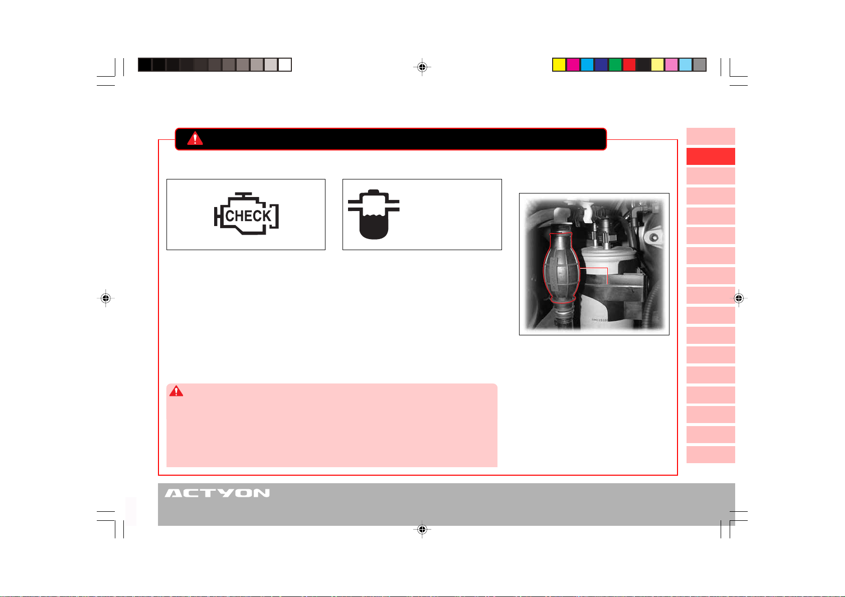
Engine Check Indicator Priming Pump Operating
Water Separator Warning Light
Conditions
Can be performed
when engine oil is
changed
The Engine check indicator on the instrument cluster comes on when the
fuel or major electronic systems of the
engine are not working properly. As a
result, the engine’s power output may
decrease or the engine may stall. If this
happens, please visit the nearest
Ssangyong dealer or authorized service
operator.
WARNING
• When engine check warning light comes on, immediately stop driving and have the engine system checked at a Ssangyong Dealer or Ssangyong Authorized Service Center.
• Drain the water from fuel filter & water separator immediately after the water separator
warning light comes on.
• The fuel system in the engine may get seriously damaged if you keep driving while the
warning light is on.
When the water level inside of the water drain in the fuel filter exceeds a certain level, this warning light and an
alarming sound are activated. In
addition, the driving force of the vehicle
decreases. If this happens, immediately
drain the water from the fuel filter.
Please refer to Chapter 5 “How to drain
the water from the fuel filter” in this
manual.
Priming Pump
1. When completely consumed the
fuel
2. After draining the water from the
fuel filter
3. After replacing the fuel filter
- If this happens, pump fuel until the
priming pump is fully filled. Then,
start the engine.
1
2
3
4
5
6
7
8
9
10
11
12
13
14
15
16
C100_RHD_01-Safety Precautions.p65 2006-05-16, ¿ÀÈÄ 8:2711
SAFETY PRECAUTIONS
1-11
Page 26

MEMO
.....................................................................................................................................................................................................................................................................................................................................................................................................................................................................................
.....................................................................................................................................................................................................................................................................................................................................................................................................................................................................................
.....................................................................................................................................................................................................................................................................................................................................................................................................................................................................................
.....................................................................................................................................................................................................................................................................................................................................................................................................................................................................................
.....................................................................................................................................................................................................................................................................................................................................................................................................................................................................................
.....................................................................................................................................................................................................................................................................................................................................................................................................................................................................................
.....................................................................................................................................................................................................................................................................................................................................................................................................................................................................................
.....................................................................................................................................................................................................................................................................................................................................................................................................................................................................................
.....................................................................................................................................................................................................................................................................................................................................................................................................................................................................................
.....................................................................................................................................................................................................................................................................................................................................................................................................................................................................................
.....................................................................................................................................................................................................................................................................................................................................................................................................................................................................................
.....................................................................................................................................................................................................................................................................................................................................................................................................................................................................................
.....................................................................................................................................................................................................................................................................................................................................................................................................................................................................................
.....................................................................................................................................................................................................................................................................................................................................................................................................................................................................................
.....................................................................................................................................................................................................................................................................................................................................................................................................................................................................................
C100_RHD_01-Safety Precautions.p65 2006-05-16, ¿ÀÈÄ 8:2712
Page 27
0
Ignition Key, Remote Control Key
TABLE OF CONTENTS
Remote Control Key* and Ignition Key ...... 2-2
Remote Control Key Functions................... 2-4
Key Functions .............................................. 2-6
Immobilizer System* ................................... 2-8
Opening and Closing the Doors and Tailgate
with Ignition Key ....................................... 2-10
Theft Deterrent System ..............................2-11
2
1
2
3
4
5
6
7
8
9
10
11
12
13
14
15
C100_RHD_02-Ignition Key, Remote Control Key.p65 2006-05-16, ¿ÀÈÄ 8:271
16
Page 28
REMOTE CONTROL KEY* AND IGNITION KEY
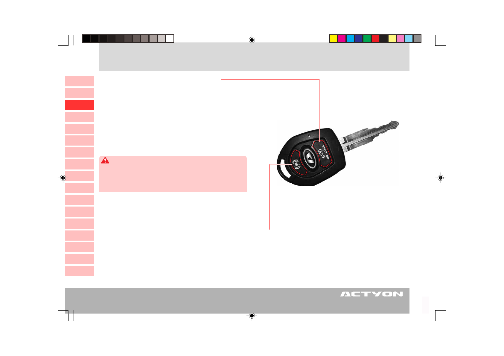
DOOR LOCK/UNLOCK BUTTON
0
1
1. Lock (Briefly press)
2
3
4
5
6
7
8
9
10
11
12
13
14
15
16
If you press this button briefly, all doors and the tailgate
are locked and the theft deterrent mode is activated.
2. Unlock (Press and hold)
If you press and hold this button for a certain period of
time, all doors and the tailgate are unlocked and the theft
deterrent mode is deactivated.
CAUTION
• The doors cannot be locked by remote control if they are not
closed.
• If you lose your keys, you have to replace the whole key set to
prevent from theft.
WHEN A REMOTE CONTROL KEY IS LOST
When one of the remote control keys is lost and a new remote control key is purchased, bring the other old remote
control key (dual REKES type) to the nearest Ssangyong
Dealer or Ssangyong Authorized Service Center and have it
recoded. Otherwise, the old key will not work.
PANIC BUTTON*
(operative only when the ignition key is
inserted)
Sounds intermittent buzzer for about 27 seconds
2-2
C100_RHD_02-Ignition Key, Remote Control Key.p65 2006-05-16, ¿ÀÈÄ 8:272
IGNITION KEY, REMOTE CONTROL KEY
Page 29
SIMULTANEOUS OPERATIONS OF ROOM
LAMPS
The front and center room lamps come on for 30 seconds
when the unlock button on the remote control is pressed
and hold.
The lamps immediately go off when the remote lock button
is pressed.
AUTOMATIC DOOR LOCKING
If a door is not opened within 30 seconds after unlocking
the door with the remote control key, all the doors will be
locked automatically.
FUNCTIONS OF IMMOBILIZER
Immobilizer Function
The immobilizer is designed to prevent the possibility of vehicle theft by allowing only authorized keys to start the engine.
The same code is encrypted in the transponder inside of
the key and in the Engine Control Unit (ECU). When the key
is inserted and turned to the “ON” position, the ECU checks
the code from the key and allows the engine to start only
when the two codes are matched.
CAUTION
• The key and the immobilizer antenna coil should be avoided from
any electronic or magnetic equipment which may interfere with
the transponder. This may cause malfunctions of the immobilizer
function of the key.
0
1
2
3
4
5
6
7
8
9
10
11
12
13
NOTE
• Standard key does not have the remote control function.
• In case of the remote control key, some keys come with the
immobilizer and battery as an optional package
C100_RHD_02-Ignition Key, Remote Control Key.p65 2006-05-16, ¿ÀÈÄ 8:273
IGNITION KEY, REMOTE CONTROL KEY
14
15
16
2-3
Page 30
REMOTE CONTROL KEY FUNCTIONS
PANIC BUTTON*
0
1
1. Panic function
2
3
4
5
• If you are in your vehicle and feel threatened while the
ignition key is inserted into the key switch, you may activate the alarm to call attention. If you press this button,
the warning siren will sound for approx. 27 seconds.
• The siren will stop when any of the buttons on the remote control key is pressed.
6
NOTE
7
The alarm sounds only when the ignition key is inserted into the
key switch hole.
8
9
10
11
CAUTION
• The doors cannot be locked by remote control if they are not closed.
• The electronic device inside the remote control is very susceptible to moisture or heat. Please avoid any hot or humid places
to minimize any malfunctions.
12
13
14
DOOR LOCK/UNLOCK BUTTON
1. Lock (briefly press)
• If you press this button, all doors are locked and the
theft deterrent mode is activated.
• When the theft deterrent mode is activated, the emergency hazard lights blink twice.
2. Unlock (press and hold)
• If you press and hold this button for about 1 seconds,
it unlocks all doors and releases the theft deterrent
mode.
• When the deterrent mode is deactivated, the emergency
hazard lights blink once.
• The front and center room lamps come on for 30 seconds when the doors are unlocked with the remote control key.
15
16
2-4
C100_RHD_02-Ignition Key, Remote Control Key.p65 2006-05-17, ¿ÀÀü 9:41Page 4 Adobe PageMaker 6.5K/Win
IGNITION KEY, REMOTE CONTROL KEY
Page 31

BATTERY REPLACEMENT
When the operational distance noticeably decreases or the
remote control does not work occasionally, replace the battery with a new one.
Battery Replacement (With Rekes)
1. Unscrew two screws from the rear cover.
0
1
2
Battery Specifications
Model
Amount
CAUTION
• Use only the specified battery.
• Make sure that the battery is installed in correct direction.
CR 2032
One
2. Pry off the cover by using a small flat screwdriver.
Model: CR2032
3. Remove the battery and insert a new one.
3
4
5
6
7
8
9
10
11
12
13
14
15
16
C100_RHD_02-Ignition Key, Remote Control Key.p65 2006-05-16, ¿ÀÈÄ 8:275
IGNITION KEY, REMOTE CONTROL KEY
2-5
Page 32

KEY FUNCTIONS
10
11
12
13
14
15
16
0
1
2
3
4
5
6
LOCK position
• The ignition key can only
be inserted or withdrawn.
• The steering wheel can be
locked.
7
Unlocking the Steering Wheel
8
To unlock the steering wheel, insert the
9
key and gently turn it to the ACC or ON
position while slightly moving the steering wheel right and left.
Key hole illumination*
The illumination lamp comes on when
opening the door. This lamp goes out
about 10 seconds after closing the door.
Key reminder
The buzzer will sound if the driver’s door
is opened while the key is left in the ignition switch on the condition that the ignition key is in the ACC or ON position.
ACC position
• Allows operation of some electrical accessories with
the engine off.
• Unlock the steering wheel.
• The ignition key cannot be removed.
From ACC to LOCK position:
Turn the key to LOCK position from
ACC position while pressing the key.
ON position
• The engine runs and all electrical accessories can be used.
• The steering wheel is unlocked.
START position
• Engages the starter. After the
engine starts, release the key
and it will automatically return
to the “ON” position.
Key Hole Illumination
2-6
C100_RHD_02-Ignition Key, Remote Control Key.p65 2006-05-16, ¿ÀÈÄ 8:276
IGNITION KEY, REMOTE CONTROL KEY
Page 33

CAUTIONS WHEN STARTING THE ENGINE
• To unlock the steering wheel, insert the key and gently
turn it to the
steering wheel right and left.
• The engine in a manual transmission equipped vehicle
can only be started when the clutch pedal is fully depressed.
• Diesel engine equipped vehicle: Turn the ignition key
to the
goes out. After then, turn the ignition key to the
“START” position and hold it until the engine starts.
But do not hold the ignition key at the
tion for more than 10 seconds.
• The engine in an automatic transmission equipped vehicle can be started only when the selector lever is at
“P” or “N” position.
the
• Keep the brake pedal depressed when starting the
engine.
• If the engine fails to start, even if the engine does not
start, turn the key back to the
wait for 10 seconds. Then try again, before any attempt
to start the engine.
• After starting the engine, let it run for approx. 2 minutes
at idle speed. Do not accelerate the engine during the
warming up period.
“ACC” position while slightly moving the
“ON” position and wait until the glow indicator
“START” posi-
“LOCK” position and
• A warning buzzer sounds when opening the driver’s door
with the key positioned at the
position.
• Do not leave the key at the
when engine is not running. Otherwise, the battery could
run down.
• Never press down the accelerator pedal while starting.
• Do not operate the starter for more than 10 seconds at
a time. (The starter motor may be damaged.)
• To prevent any damage to the starter, restart the engine from the
10 seconds.
• Never turn the key to the
draw the ignition key from the ignition switch while
driving. The steering wheel will be locked and you may
end up with serious injuries.
• Never use any duplicated key not provided from
Ssangyong.
The duplicated key might not turn back to the
position. It may cause a fire due to an overload in the
electric circuit. In addition, the engine with the immobilizer system cannot be started with the duplicated key.
“LOCK” position after waiting at least
“ACC” or “LOCK”
“ACC” or “ON” position
“LOCK” position or with-
“ON”
0
1
2
3
4
5
6
7
8
9
10
11
12
13
14
15
16
C100_RHD_02-Ignition Key, Remote Control Key.p65 2006-05-16, ¿ÀÈÄ 8:277
IGNITION KEY, REMOTE CONTROL KEY
2-7
Page 34

IMMOBILIZER SYSTEM*
The Immobilizer System provides an additional theft deterrent to the vehicle in which it is installed and prevents it from being
0
started by unauthorized persons. The transponder integrated in the key and the engine control unit have the same code.
When the ignition key with the integrated transponder is turned to the ON position, the ECU (Engine Control Unit) checks the
1
crypto code of the key and, if correct, allows your vehicle to start the engine.
10
11
12
13
14
15
16
2
3
4
5
6
7
8
9
Immobilizer Key
When the ignition key with the integrated
transponder is turned to the ON position,
the ECU (Engine Control Unit) checks the
crypto code of the key and, if correct, allows
your vehicle to start the engine.
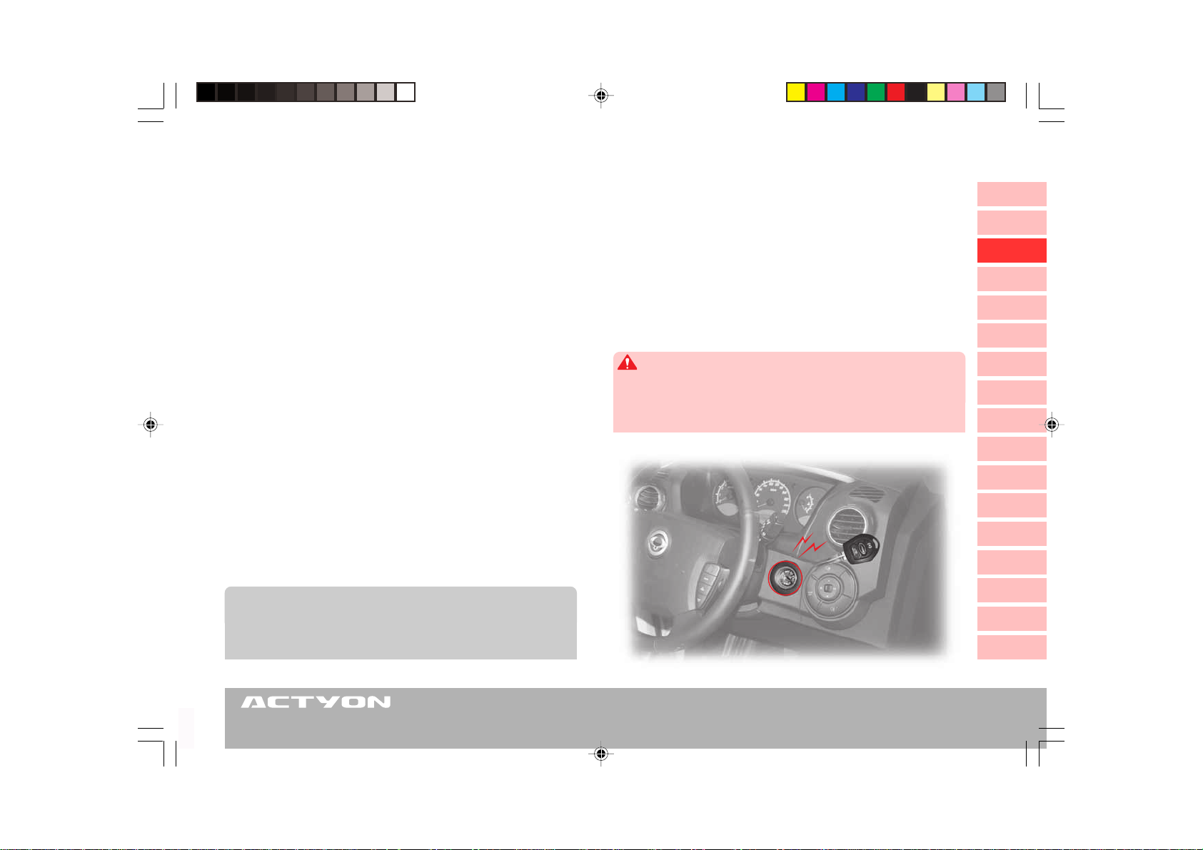
Immobilizer Indicator
This indicator comes on when the ignition key is communicating with the engine control unit (during engine starting)
and goes out after starting the engine.
If this indicator blinks, it may indicate
that there is something wrong in the immobilizer system. Have the system
checked by a Ssangyong Dealer or
Ssangyong Authorized Service Center.
NOTE
The time needed for communication between the immobilizer
key and ECU can vary. When the time is very short, the immobilizer indicator does not come on.
Transponder
Battery
Key plate
2-8
C100_RHD_02-Ignition Key, Remote Control Key.p65 2006-05-16, ¿ÀÈÄ 8:278
IGNITION KEY, REMOTE CONTROL KEY
Page 35

• When the Transponder is Damaged
When the transponder is damaged, you must replace it
with a new one and register a new code on the engine
control unit at a Ssangyong Dealer or Ssangyong Authorized Service Center. Otherwise, the engine cannot be
started.
• When Your Key is Lost
When your key is lost, the encrypted code should be removed from the Engine Control Unit to avoid any vehicle
theft. Please contact a Ssangyong Dealer or Ssangyong
Authorized Service Center.
WARNING
• In any case, the immobilizer system cannot be removed from
the vehicle. If you attempt to remove and damage the system,
it is impossible to start the engine. So never attempt to remove,
damage or modify it.
• In addition, any remote engine starter cannot be installed to the
vehicle equipped with the immobilizer system. So never install
any remote engine starter.
CAUTION
• When you modify your vehicle and install a remote engine starter,
you may have some problems starting the engine or some fatal
accidents.
In the following cases, you may be unable to start the
vehicle with the immobilizer.
X When two or more immobilizer keys come into con-
tact with (each) other(s).
X When the key is close to any device sending or re-
ceiving electromagnetic fields or waves.
X When the key is close to any electronic or electric
devices such as lighting equipment, security keys
or security cards.
X When the key is close to a magnetic or metal ob-
ject or a battery.
CAUTION
• If the indicator remains blinking, have the immobilizer system
checked by a Ssangyong Dealer or Ssangyong Authorized Service Center.
• Avoid impact to the transponder inside of the key. The transponder can be damaged.
• With a damaged transponder, the engine cannot be started.
• The immobilizer system should be inspected, replaced,
serviced, or coded by only qualified service personnel in a
Ssangyong Dealer or Ssangyong Authorized Service Center.
• When an old code should be replaced or another key is added,
please observe the process personally.
0
1
2
3
4
5
6
7
8
9
10
11
12
13
14
15
16
C100_RHD_02-Ignition Key, Remote Control Key.p65 2006-05-16, ¿ÀÈÄ 8:279
IGNITION KEY, REMOTE CONTROL KEY
2-9
Page 36

OPENING AND CLOSING THE DOORS AND TAILGATE WITH IGNITION KEY
0
1
2
3
4
5
6
7
8
9
10
11
12
13
14
If the starting key is turned to the
15
arrow pointed direction, the tailgate
will be opened.
16
2-10
C100_RHD_02-Ignition Key, Remote Control Key.p65 2006-05-16, ¿ÀÈÄ 8:2710
IGNITION KEY, REMOTE CONTROL KEY
Locking the door and the tailgate
Unlocking the door and the tailgate
To lock the door:
Turn the key to the lock position (toward front of the vehicle) from driver’s
door or passenger’s door. All doors and the tailgate will be locked.
To unlock the door:
Turn the key to the unlock position (toward rear of the vehicle) from driver’s
door or passenger’s door. All doors and the tailgate will be unlocked.
Automatic Door Unlocking:
All doors will be automatically unlocked when the engine is switched off.
CAUTION
When you unlock the door with the ignition key after the door is locked with the
remote control (the theft deterrent mode), a warning buzzer sounds. Stop the
buzzer by pressing any button on the remote control.
Page 37

THEFT DETERRENT SYSTEM
ARMING THE THEFT DETERRENT SYSTEM
The theft deterrent system will be armed under the following conditions:
• When all doors are locked with the remote control key, the anti-theft mode will be activated. If the
“UNLOCK” button on the remote control key is pressed and no door is opened within approxi-
mately 30 seconds, all doors are automatically locked again and the anti-theft mode will be activated.
• When the theft deterrent system is armed, the emergency hazard lights blink twice.
CAUTION
• To arm the theft deterrent system, the ignition key should be removed from the ignition switch, all doors including
the tailgate and the hood should be closed completely.
• Activation of the theft deterrent system can be confirmed by the emergency hazard lights blinking twice.
THEFT DETERRENT SYSTEM ALARM STAGE
If somebody tries to open the door, the tailgate or the hood without using the remote control key, the
alarm will be activated.
• When one of the doors or the tailgate is opened with the ignition key while the deterrent system is
armed, the alarm will sound.
• The engine hood or the tailgate is opened from the outside while the deterrent system is armed, the
alarm will be activated.
• When the alarm is activated, warning sound and the emergency hazard lights will be on and off every
second for 27 seconds.
DISARMING THE THEFT DETERRENT SYSTEM
• Unlock the door by using the remote control key.
• To deactivate the theft deterrent mode at the alarming stage, unlock the door by using the remote
control key.
• When the deterrent system is disarmed, the emergency hazard lights blink once.
0
1
2
3
4
5
6
7
8
9
10
11
12
13
14
15
16
C100_RHD_02-Ignition Key, Remote Control Key.p65 2006-05-16, ¿ÀÈÄ 8:2711
IGNITION KEY, REMOTE CONTROL KEY
2-11
Page 38

MEMO
.....................................................................................................................................................................................................................................................................................................................................................................................................................................................................................
.....................................................................................................................................................................................................................................................................................................................................................................................................................................................................................
.....................................................................................................................................................................................................................................................................................................................................................................................................................................................................................
.....................................................................................................................................................................................................................................................................................................................................................................................................................................................................................
.....................................................................................................................................................................................................................................................................................................................................................................................................................................................................................
.....................................................................................................................................................................................................................................................................................................................................................................................................................................................................................
.....................................................................................................................................................................................................................................................................................................................................................................................................................................................................................
.....................................................................................................................................................................................................................................................................................................................................................................................................................................................................................
.....................................................................................................................................................................................................................................................................................................................................................................................................................................................................................
.....................................................................................................................................................................................................................................................................................................................................................................................................................................................................................
.....................................................................................................................................................................................................................................................................................................................................................................................................................................................................................
.....................................................................................................................................................................................................................................................................................................................................................................................................................................................................................
.....................................................................................................................................................................................................................................................................................................................................................................................................................................................................................
.....................................................................................................................................................................................................................................................................................................................................................................................................................................................................................
.....................................................................................................................................................................................................................................................................................................................................................................................................................................................................................
C100_RHD_02-Ignition Key, Remote Control Key.p65 2006-05-16, ¿ÀÈÄ 8:2712
Page 39

0
Opening and Closing
TABLE OF CONTENTS
Opening and Closing Devices .................... 3-2
Doors ............................................................ 3-3
Windows....................................................... 3-5
Sunroof* ....................................................... 3-7
Tailgate ........................................................ 3-9
Engine Hood .............................................. 3-10
Fuel Filler Door........................................... 3-11
3
1
2
3
4
5
6
7
8
9
10
11
12
13
14
15
C100_RHD_03-Opening and Closing.p65 2006-05-16, ¿ÀÈÄ 8:271
16
Page 40

OPENING AND CLOSING DEVICES
0
1
2
3
4
5
6
Child Safety Door Lock
7
8
Lock
9
10
11
12
Door Opening Lever
13
14
15
16
Unlock
Driver’s Door
Windows Switch
Tailgate Opening Key Hole
Fuel Filler Door Release Lever,
Engine Hood Opening Lever
Fuel Filler DoorTailgate Opening SwitchSunroof Controller
Engine Hood Safety
Latch Lever
Fuel filler door
release lever
Engine hood
opening lever
3-2
C100_RHD_03-Opening and Closing.p65 2006-05-16, ¿ÀÈÄ 8:272
OPENING AND CLOSING
Page 41

DOORS
Door Lock/Unlock Knob
All doors will be locked/unlocked when
moving the knob to the respective lock/
unlock direction (only available at
driver’s and front passenger’s door).
Door Opening Lever
Pull the door opening lever to open
the door.
NOTE
• The passenger’s door lock/unlock knob and lever have the same functions with those of the
driver’s door.
• The door lock/unlock knob on the rear right or
rear left door can only lock or unlock its respective door.
• Even though the driver’s door is locked, the
door can be opened when the opening lever
on the door is pulled.
Child Safety Door Lock
Child safety door lock helps
prevent from an accidental
door open, especially when
children are in the vehicle.
When the child-safe lever is
in the
the rear door can be opened
only from the outside.
“LOCK” position,
WARNING
Children in rear seats can open rear doors. Move the child-safe
lever to the
“LOCK” position.
Lock
Unlock
Unlock
Lock
Door Lock/Unlock Knob
Door Opening Lever
Central Door Lock/
Unlock Switch
Driver’s door
0
1
2
3
4
5
6
7
8
9
10
11
12
13
14
15
16
C100_RHD_03-Opening and Closing.p65 2006-05-16, ¿ÀÈÄ 8:273
OPENING AND CLOSING
3-3
Page 42

CENTRAL DOOR LOCK/UNLOCK SWITCH
0
1
2
3
4
5
6
7
8
Automatic Door Unlocking
9
When the airbag deploys while all doors are automatically
10
locked by the Automatic Door Locking System, the doors
will automatically be unlocked.
11
12
13
WARNING
When damage is done on a door or the body frame by an impact from
an accident, the automatic door unlocking system may not work.
Passenger’s sideDriver’s side
When the door lock/unlock switch is
pressed while all doors including the tailgate are locked, all doors will be
unlocked. When the switch is pressed
again, all doors will be locked.
This switch is not available when any of
doors are not fully closed and the vehicle
is in theft deterrent mode.
Automatic Door Locking
All doors will be automatically locked when you drive over
50 km/h while the doors are unlocked.
CAUTION
When you drive at 50 km/h or a higher speed and try to unlock all
doors with the door lock/unlock knob or switch, all doors are automatically locked again.
14
15
16
C100_RHD_03-Opening and Closing.p65 2006-05-16, ¿ÀÈÄ 8:274
NOTE
• When any door is open, all doors can not be locked by using the
door lock knob, the central door lock/unlock switch, or the remote control.
• When the engine is turned off, all doors become unlocked.
3-4
OPENING AND CLOSING
Room Lamp Synchronized Operation
The center room lamp is synchronized with the door switch.
When any door is open, the front and center room lamps
come on. The lamps will automatically turn off in about 30
seconds. When any door is closed, the lamps will dim down
and go out.
Page 43

WINDOWS
Window Lock Switch
If the window lock switch is pressed down,
passenger’s and rear windows cannot be operated by their switches.
WARNING
When carrying children in the rear seat, press the
window lock switch to make the rear window
switches inoperative. Do not allow children to play
with the power window switch and rear door
window switches.
CAUTION
When closing the passenger’s and rear windows
from driver’s seat, be aware of safety conditions
before operation. Parts of the body can be trapped
by the window.
Central Door Lock/
Unlock Switch
Time Lag of Window Operation
The power window can be operated for 30
seconds even after the ignition key is turned
to another position from the “ON” position.
However, the function immediately stops
when one of the front doors is opened.
Passenger’s Door
Window Switch
Rear Right Window Switch
Driver’s Door Window Switch
• When the front of the switch is lightly
pressed, the window will be lowered while
the switch is pressed.
• When pressed to its end, the window will
open automatically until it is fully open. If you
want to stop the window while automatic
lowering, lightly press the switch again or
pull the switch up.
XX
X When closing the window
XX
• When you lightly pull the switch up, the window will move up only while the switch is
being operated.
• When pulling the switch up to its end, the window will be fully closed (auto-up operation*).
If you want to stop the auto-up function, pull
up or gently press the switch again.
Rear Left
Window Switch
0
1
2
3
4
5
6
7
8
9
10
11
12
13
14
15
16
C100_RHD_03-Opening and Closing.p65 2006-05-16, ¿ÀÈÄ 8:275
OPENING AND CLOSING
3-5
Page 44

Anti-Trap System for Driver’s Window
0
The anti-trap system enables the driver’s window to auto-
1
matically reverse when something is caught in the window
as it is closing. When the sensor detects an obstacle, the
2
window will be lowered immediately.
3
4
5
CAUTION
• The anti-trap safety system is available only for the driver’s window equipped with the automatic rolling up (Auto-up) function.
• The anti-trap safety system does not operate when the window is about to touch its window frame.
6
7
Passenger’s and Rear Window Switch
Passenger’s seat
Door Lock/Unlock Switch
8
9
10
11
12
13
14
15
16
3-6
C100_RHD_03-Opening and Closing.p65 2006-05-16, ¿ÀÈÄ 8:276
OPENING AND CLOSING
Window switch
Rear seat
WARNING
• Before operating the power windows, make sure that nothing
can be trapped (such as heads, hands, or fingers) in the window.
• Make sure that passengers do not stick out their hands or heads
from the vehicle while driving.
• Do not allow children to play with any switch, door lever or the
gear shift lever.
To move windows up or down,
press or pull up the corresponding switch for the
window.
Page 45

SUNROOF*
* For your safety, never operate the sunroof when the vehicle is moving.
SUNROOF SLIDING OPERATION
XX
X Open: 2-Step Opening
XX
When the sunroof is closed, two thirds of the sunroof automatically opens if the sunroof open/close switch is
turned to the “OPEN” direction (Clockwise).
When the switch is turned again to the “OPEN” direction,
the sunroof completely opens.
When the switch is operated while the sunroof is moving,
the sunroof stops sliding.
XX
X Close
XX
When the sunroof is open, turn the switch to the “CLOSE”
direction (counterclockwise) to close it completely. To stop
the closing sunroof, operate the switch to either direction.
SUNROOF TILTING OPERATION
XX
X Tilt Up
XX
When the sunroof is closed, turn the switch to the
“CLOSE” direction (counterclockwise) to tilt up the rear
of the sunroof.
XX
X Tilt Down
XX
When the rear of the sunroof is tilted up, turn the switch
to the “OPEN” position (clockwise) to close the sunroof.
WIND BUFFETING
When you drive this vehicle with the window or sunroof open
at a certain position, you may feel some pressure upon your
ears or hear some noises similar to those from a helicopter.
This happens because of an influx in air through the window or sunroof and its resonance effect. If this happens,
adjust by opening the window or sunroof.
Anti-Pinch Function
To prevent any body parts from being trapped by the sliding
sunroof, an Anti-Pinch Function automatically opens the
sunroof when an object is trapped.
CAUTION
• This safety function is available for the sliding sunroof close.
• The anti-Pinch function is deactivated just before the sunroof closes.
• If the anti-pinch is operated 3 times in series, the system is
changed to manual mode.
WARNING
• When operating the sunroof, be aware of safety conditions before
operation. Parts of the body can be trapped.
OPENING AND CLOSING
3-7
0
1
2
3
4
5
6
7
8
9
10
11
12
13
14
15
16
C100_RHD_03-Opening and Closing.p65 2006-05-16, ¿ÀÈÄ 8:277
Page 46

10
11
12
13
14
15
16
0
1
2
3
4
5
6
7
8
9
CAUTION
• Even though the sunroof can be operated when the ignition key is
in the ON position (the engine is not running), operating the
sunroof repeatedly with the engine turned off will run down the
battery. Operate the sunroof while the engine is running.
• When a desired sunroof operation is completed, release the switch.
If you keep pressing the switch, it could cause a malfunction.
Especially in the winter, never operate the sunroof if moving areas are iced. Wait until the areas are deiced.
• When leaving the vehicle unattended, be sure to completely close
the sunroof. Otherwise, there is a great risk of vehicle theft. Or, the
interior of the vehicle will be wet when it rains or snows.
• When the sunroof is slid to its complete open position, the wind
buffet phenomenon can increase. If this happens, adjust by opening the sunroof or only open two thirds of the sunroof by using
only the first step of the opening system.
Battery Discharge or Power Failure while
Operating Sunroof
If the sunroof is stopped midway due to a discharged battery or
power failure, you need to re-calibrate the starting point of the
sunroof. In addition, the following cases need the re-calibration.
• The sunroof does not completely close or open by operating the switch once.
• The sunroof slides back to close. But the operation does
not stop even after a complete close and tilts up the sunroof.
• The opening gap remarkably decreases for the sliding open
or tilt up.
• Operation of the sunroof switch does not do anything or
work properly.
Re-calibrating the Sunroof Starting Point
• Turn the sunroof switch to the “CLOSE” direction to completely close the sunroof (sliding close).
• When the sunroof stops while the rear of the sunroof is
a little open, turn the sunroof switch to the “CLOSE” direction to tilt it completely.
NOTE
When the sunroof is completely opened with the sunroof switch and
the switch is turned to the “OPEN” direction for more than 5 seconds,
the sunroof cannot completely be either closed or opened by operating the switch once. The sunroof will be moving only when the switch
is being turned. When this happens, re-calibrate the beginning point
of the sunroof to reactivate the one touch button.
3-8
C100_RHD_03-Opening and Closing.p65 2006-05-16, ¿ÀÈÄ 8:278
OPENING AND CLOSING
Page 47

TAILGATE
Tailgate Open Switch
When the tailgate is unlocked and your
vehicle completely stops, press the tailgate open switch for a while to open the
tailgate. When the door lock/unlock switch
is engaged in the “LOCK” position, the
tailgate will not be opened.
Opening the Tailgate with Ignition Key
When opening the tailgate
Turn the ignition key to the open position on the tailgate.
Tailgate Open/Close
After unlocking the tailgate with the tailgate open switch or the ignition key,
lift up the tailgate to open the tailgate completely. To close the tailgate, pull
down the tailgate strap to lower the gate. Then, push the tailgate to close it
completely.
WARNING
Before closing the tailgate, ensure that none of your body parts are trapped. Also,
because the tailgate is heavy, it might unexpectedly fall down and close. To prevent
any injury, close the tailgate with caution.
0
1
2
3
4
5
6
7
8
9
10
11
12
13
14
15
16
C100_RHD_03-Opening and Closing.p65 2006-05-16, ¿ÀÈÄ 8:279
OPENING AND CLOSING
3-9
Page 48

ENGINE HOOD
10
11
12
13
14
15
16
0
1
2
3
4
5
6
7
8
9
WARNING
• When you open the hood while the
engine is running, extra caution is
needed to avoid any injuries by the
moving parts in the engine
compartment.
• Before driving, try to pull up the front
edge of the hood to check that the
hood is securely latched.
• When it is windy, extra caution is
needed to prevent personal injury.
Wind might be able to lift up the
hood and the prop rod may be disengaged from its slot. This may result in an unexpected closing of the
hood.
1. To open the engine hood, pull the
release knob located on the lower
left side of the steering wheel to
unlatch the engine hood.
2. Slightly lift up the engine
hood and raise up the safety
latch lever with your fingers.
Then, completely lift up the
engine hood.
3. After lifting up the hood, secure it with the prop rod. Insert the rod's free end into
its slot on the hood to prevent the hood from suddenly
closing.
3-10
C100_RHD_03-Opening and Closing.p65 2006-05-16, ¿ÀÈÄ 8:2710
OPENING AND CLOSING
Page 49

FUEL FILLER DOOR
1. Open the fuel filler door ( ) by pulling the
release lever located on the lower left side
of the steering wheel.
WARNING
• Always stop the engine when refueling. Use only the designated fuel
and low sulfur diesel.
• When refueling, • No smoking.
• No naked flame. • No sparking material.
• If you use inappropriate grade fuel or put improper fuel additives into the
fuel tank, the engine and catalytic converter may seriously be damaged.
• Check the type of fuel before fueling your vehicle. If gasoline is fueled into
a diesel-engine vehicle, this may have negative effects upon its fuel system and other vehicle systems and bring serious damage to your vehicle.
CAUTION
• Fuel damages paintwork. If fuel spills onto paintwork, immediately wash
the affected area with cold water.
• The fuel filler door may not open in cold weather. Gently tap the fuel filler
door to open.
OPEN
CLOSE
2. Open the fuel filler cap ( ) by
turning it counterclockwise.
3. After refueling, tighten the fuel
filler cap by turning it clockwise
until you hear clicking sounds.
Then close the fuel filler lid (
properly until it latches.
0
1
2
3
4
5
6
)
7
8
9
10
11
12
13
14
15
16
C100_RHD_03-Opening and Closing.p65 2006-05-16, ¿ÀÈÄ 8:2711
OPENING AND CLOSING
3-11
Page 50

0
10
11
12
13
14
15
1
CAUTIONS WHEN OPENING / CLOSING DOORS
2
• Do not allow children to play with any switch, door lever and the gear shift.
3
• Before operating the power windows, doors, sunroof, tailgate and fuel filler door, make sure that noth-
4
5
6
7
ing can be trapped (such as heads, hands, or fingers).
• Make sure that the doors, sunroof, tailgate and fuel filler door are completely closed before driving.
• When a child is on board, use the child safety functions to avoid any unwanted and dangerous opening of doors or windows.
• Parts of the human body can be trapped in the window or sunroof and can be struck by passing objects.
Do not stick hands, heads or anything else out of the openings.
8
9
16
3-12
C100_RHD_03-Opening and Closing.p65 2006-05-16, ¿ÀÈÄ 8:2712
OPENING AND CLOSING
Page 51

0
Interior Switches
TABLE OF CONTENTS
Interior Switches ......................................... 4-2
Light Switch ................................................. 4-4
Wiper and Washer Switch .......................... 4-8
Rain Sensing Wiper* ................................. 4-10
Cruise Control Switch (For Auto T/M*) ...... 4-11
Outside Rearview Mirror Control Switch and
Rear Fog Light Switch .............................. 4-15
ESP
and ESP System* ....................................... 4-16
Center Switch Panel ................................. 4-18
HDC (Hill Descent Control) Switch* .......... 4-20
Heated Glass Switch ................................. 4-22
(Electronic Stability Program) Switch
OFF
4
Audio Remote Control Switches on Steering
Wheel ......................................................... 4-23
4-wheel Drive Switch* ............................... 4-24
Cautions When Using 4-wheel Drive Mode
.................................................................... 4-25
Switches in Overhead Console ................ 4-26
1
2
3
4
5
6
7
8
9
10
11
12
13
14
15
16
C100_RHD_04-Interior Switches.p65 2006-05-16, ¿ÀÈÄ 8:271
Page 52

INTERIOR SWITCHES
0
1
2
3
10
11
12
13
14
15
16
4
5
6
Sunroof switch
Wiper and washer switch
Audio remote control switch
7
8
Light switch
9
Door lock/
4-2
unlock switch
Passenger seat heating switch
INTERIOR SWITCHES
4-wheel drive switch
Driver seat heating switch
Headlight leveling switch
Winter/Power mode switch
Auto cruise*
Window control
switches
Door lock/unlock switch
C100_RHD_04-Interior Switches.p65 2006-05-16, ¿ÀÈÄ 8:272
Page 53

0
ESP OFF switch*
Hazard warning flasher switch
Outside rearview mirror*
folding switch
Outside rearview mirror
control switch
Rear fog light switch*
Outside rearview mirror selection switch
HDC switch*
Tailgate and outside rearview
mirror heated glass switch
Windshield heated glass switch
1
2
3
4
5
6
7
8
9
10
11
12
13
14
15
C100_RHD_04-Interior Switches.p65 2006-05-16, ¿ÀÈÄ 8:273
TRIP/RESET switch
INTERIOR SWITCHES
16
4-3
Page 54

LIGHT SWITCH
Light Switch
0
1
Front fog light
switch
2
3
4
5
6
You can turn the lights on and off
(headlamps, tail lights, position
7
lamps, license plate lamp, turn signal lamps, fog lights) with this
8
switch.
9
10
11
12
13
Turn signal lamp
14
15
Front fog light
16
Automatic Light
(Rain Sensor*)
This senses the ambient illumination intensity to determine
the timing for turning the
headlamps and tail lights on or
off automatically when the light
switch is set to “AUTO”.
Headlamp
High-mounted stop lamp
License plate lamp
Tail light/Stop lamp
Turn signal lamp
Back-up lamp
Rear fog light*
4-4
C100_RHD_04-Interior Switches.p65 2006-05-16, ¿ÀÈÄ 8:274
INTERIOR SWITCHES
Page 55

AUTOMATIC LIGHT*
0
Rain Sensor*
This senses the amount of rain to operate the windshield
wiper automatically (For detailed information of wiper
operation, refer to wiper and washer switch section).
CAUTION
Do not shake and impact the sensor. It may not work properly.
AUTO
The auto light and rain sensor senses the ambient illumination intensity to determine the timing for turning the
headlamps and tail lights on or off automatically when the
light switch is set to “AUTO”.
CAUTION
• Do not clean the sensor with detergent or wax.
• On a foggy, snowy, rainy, or cloudy day, be sure to use manual
mode. The turning on or off time of the lamps varies depending on
the climate, season, or circumstances.
• Any aftermarket tanning film or spray may cause the lighting system to malfunction.
• Ssangyong recommends you to use this device restrictively around
only a sunrise or sunset.
• Usually turn the head or tail lights on or off manually.
• Turn on the headlamps when passing through a dark area such as
a tunnel.
• On a gloomy day, do not rely on this automatic function. But turn
the head or tail lights on or off manually.
• When the switch is turned to the “AUTO” position, room, tail, and
head lights might blink for a very short time. It is a normal phenomenon recognizing the automatic setting.
1
2
3
4
5
6
7
8
9
10
11
12
13
14
15
16
C100_RHD_04-Interior Switches.p65 2006-05-16, ¿ÀÈÄ 8:275
INTERIOR SWITCHES
4-5
Page 56

10
11
12
13
LIGHT SWITCH
Headlight Leveling Switch
0
1
2
Head-, side-marker, tail, license plate, fog, and instrument cluster lamps come on.
(Headlamps ON)
3
4
5
Side-marker, tail, license plate, fog, and instrument
cluster lamps come on.
6
7
8
9
(Tail lights ON)
AUTO
Head- and tail lights automatically turn on or
off based upon the intensity of the sunlight
analyzed by the automatic light sensor.
(Automatic light ON)
OFF
All lights are off.
(Lights OFF)
With the low beam switched on, adjust the aiming angle of headlights to
suit the vehicle load.
• To lower the aiming angle, rotate
the switch upward.
• To raise the aiming angle, rotate the
switch downward.
NOTE
According to load condition, adjust the
aiming angle of headlights.
14
Battery Saver (Automatically turns off the lights)
To avoid discharging the battery, if the tail lamps are on after the ignition key is
15
removed, a buzzer will sound to alert the driver when the driver’s door is opened.
The tail lamps will automatically turn off when the door is closed. To turn the tail
16
lamps on again, insert the ignition key into the ignition switch. Or, turn the light
switch to the “OFF” position and then to the “ON” position.
4-6
C100_RHD_04-Interior Switches.p65 2006-05-16, ¿ÀÈÄ 8:276
INTERIOR SWITCHES
Page 57

Headlamp High Beam
To turn on the headlamp high beam,
push the lever towards the instrument
cluster with the headlamp low beam
on. The headlamp high beam indica-
tor (
comes on when the headlamp high
beam is turned on.
) in the instrument cluster
Right Turn Signal Switch
NOTE
While the turn signal lamp is turned on, the turn signal
indicator in the instrument cluster blinks.
Front Fog Light Switch
To turn on the fog lights, turn this switch while
the tail lights or headlamps are turned on.
0
1
2
3
4
5
6
7
8
Passing
Regardless of the position of the light
switch, if you hold the lever toward the
steering wheel, the headlights are on high
beam during the hold. The high beam indicator also illuminates on the instrument
cluster during the hold.
WARNING
Driving with high beam headlamps disturbs the
approaching vehicle’s visibility for safe driving.
Use the high beam headlamp only during very
dark situations when it is very hard to see the
road.
C100_RHD_04-Interior Switches.p65 2006-05-16, ¿ÀÈÄ 8:277
Left Turn Signal Switch
REAR FOG LIGHT SWITCH*
To turn on the rear fog light, push the rear
fog light switch while the front fog light
switch is turned on. To turn it off, push the
switch again. The rear fog lights are automatically turned off when turning off the light
switch or the front fog light switch.
Therefore, to turn on the rear fog lights,
push the rear fog light switch again after
turning on the light switch and the front fog
light switch.
INTERIOR SWITCHES
9
10
11
12
13
14
15
16
4-7
Page 58

WIPER AND WASHER SWITCH
0
FRONT WIPER SWITCH
1
2
3
4
MIST
The windshield wipers can be operated
only when you hold the switch to the
“MIST” position. The lever will return
to the “OFF” position when released.
5
6
7
OFF
Stop the operation.
8
9
10
AUTO
Operates automatically according to
the vehicle speed or amount of rain.
11
12
13
LO
Continuous wipe, slow operation
14
15
HI
Continuous wipe, fast operation
16
FRONT AUTOMATIC WIPING
SPEED CONTROL SWITCH
The interval of wiper swings can be adjusted by twisting the control knob upward or downward when the windshield wiper switch is in the AUTO position.
Fast: Fast interval
Slow: Slow interval
4-8
C100_RHD_04-Interior Switches.p65 2006-05-16, ¿ÀÈÄ 8:278
INTERIOR SWITCHES
Page 59

REAR WIPER SWITCH
When the switch is fully turned, washer
fluid will be sprayed onto the rear window glass and the wiper will also operate.
When the switch is released, it will stop
in the Rear Wiper Operation mode and
only the wiper will keep operating.
FRONT AUTO WASHER SWITCH
When the front wiper switch is off and this switch
is pressed, washer fluid will be sprayed and the
wiper will automatically operate 4 times. Then, the
fluid will be sprayed again and the wiper will automatically operate 3 times.
0
1
2
3
4
5
6
7
Rear wiper operation
OFF
Rear wiper stops
When the switch is fully turned, washer
fluid will be sprayed onto the rear window glass and the wiper will also operate.
When the switch is released, it will return to the “OFF” position and turn off
the wiper and washer.
C100_RHD_04-Interior Switches.p65 2006-05-16, ¿ÀÈÄ 8:279
Wiper and Washer Coupled Operation
Pull the lever briefly (for less than 0.6 seconds):
One wiping cycle with washer spray
Pull and hold the lever for more than 0.6 seconds:
Three wiping cycles with washer spray
While being held down, the wiper and washer will
keep working.
INTERIOR SWITCHES
4-9
8
9
10
11
12
13
14
15
16
Page 60

RAIN SENSING WIPER*
When the wiper switch is in the “AUTO” position, this sensor detects the
0
amount of rain, turns on the wiper, and controls the intermittent wiper intervals.
1
Rain and Auto Light Sensor
2
3
4
5
6
It controls the wiping speed by de-
7
tecting the amount of rain drops.
8
9
10
11
12
13
14
15
16
CAUTION
• When the wiper switch is in the “AUTO” position, the wiper will operate once if the
initial engine start is made. This may wear the wiper blades prematurely (especially
in winter). Therefore, other than rainy days, set the switch to the “OFF” position. In
winter, ensure that the wiper blades are not frozen and are not stuck to the
windshield. Otherwise, this may cause some damage to the wiper motor.
• If you use only the wipers when the glass is dry, this could scratch the glass and wear
the wiper blades prematurely. Use the wiper with the washer when the glass is dry.
• Turn the wiper switch to the “OFF” position before any car wash to avoid unwanted
operation of the wipers.
• When it does not rain, turn the wiper switch into the “OFF” position.
WARNING
When you clean the windshield over the sensor with damp clothes, the wiper may
operate suddenly. It could cause serious injury. Make sure to place the wiper switch
and ignition switch to the “OFF” position when not in use.
Wiper AUTO Position
AUTO
Rear Fog Light Switch
When the front fog light switch is
“ON” press the rear fog light switch
to turn the lights on.
NOTE
• When the light and wiper switches are in the “AUTO”
position, head lights come on if the rain sensor detects any rain. The head lights stay on for 3 minutes after the rain stops.
• The speed of the wipers becomes a little faster
when it is dark enough to turn on the automatic lights.
• When the ignition key is in the “ON” position, the wiper
will automatically operate once if the wiper switch
is turned from the “OFF” to the “AUTO” position. But
the wiper will not operate again to prevent any damage to the window even though the wiper switch
is turned from the “OFF” position to the “AUTO”
position.
4-10
C100_RHD_04-Interior Switches.p65 2006-05-16, ¿ÀÈÄ 8:2710
INTERIOR SWITCHES
Page 61

CRUISE CONTROL SWITCH (FOR AUTO T/M*)
CRUISE CONTROL
The cruise control is an automatic speed control system that maintains a desired driving speed without using the accelerator pedal.
The vehicle speed must be greater than 36 km/h to engage the cruise
control. This feature is especially useful for motorway driving.
CAUTION
Improper use of the cruise control could be dangerous.
• Do not use on winding roads.
• Do not use in heavy traffic.
• Do not use on slippery, wet roads.
This could result in a loss of control, collision, and/or personal injuries.
Setting a Desired Speed
1. To operate the cruise control, accelerate to your
desired speed using the accelerator pedal over 36
km/h.
2. When the desired speed is reached, push up the
ACCEL switch of the cruise control lever or push
down the DECEL switch for 1 second per one
switching and then release the accelerator pedal
slowly.
3. Now, the vehicle is cruised by this system with the
set speed.
4. And you can set to other vehicle speeds again with
above steps after an accelerator pedal intervention
during the cruise control running.
0
1
2
3
4
5
6
7
8
9
10
11
12
13
14
15
16
C100_RHD_04-Interior Switches.p65 2006-05-16, ¿ÀÈÄ 8:2811
INTERIOR SWITCHES
4-11
Page 62

Accelerating with the Cruise Control System
0
• While the cruise control system is running
1
1. Push up the ACCEL switch of the cruise control lever and
2
3
4
5
6
7
8
9
10
11
12
13
14
hold it until the desired speed is reached without an accelerator pedal intervention.
2. When the desired speed is reached, release the lever.
• While the cruise control system is not running
1. Accelerate using the accelerator pedal over 36 km/h.
2. Push up the ACCEL switch of the cruise control lever and
hold it.
3. And then release the accelerator pedal slowly.
4. When the desired speed is reached, release the lever.
• Tap-up while the cruise control system is running
1. Push up the ACCEL switch of the cruise control lever less
than 0.5 second per one switching while the cruise control system is running. This is a tap-up switching.
2. When you operate a tap-up switching, the vehicle is accelerated for 1.3 km/h over the previous set speed.
3. If you want to accelerate for 13 km/h, operate the tap-up
switching ten times without accelerating with the cruise
control system.
15
Decelerating with the Cruise Control System
• While the cruise control system is running
1. Push down the DECEL switch of the cruise control lever
and hold it until the desired speed is reached without a
brake pedal intervention. But the cruise control system
cannot maintain the cruise function at less than 34 km/h.
2. When the desired speed is reached, release the lever.
• When the cruise control system is not running
1. Push down the DECEL switch of the cruise control lever
and hold it.
2. And then release the accelerator pedal slowly.
3. When the desired speed is reached, release the lever.
But the cruise control system cannot maintain the cruise
function at less than 34 km/h.
• Tap-down while the cruise control system is running
1. Push down the DECEL switch of the cruise control lever
less than 0.5 second per one switching while the cruise
control system is running. This is a tap-down switching.
2. When you operate a tap-down switching, the vehicle is
decelerated for 1 km/h below the previous set speed.
3. If you want to decelerate for 10 km/h, operate the tap-down
switching ten times without the brake pedal intervention.
16
4-12
C100_RHD_04-Interior Switches.p65 2006-05-16, ¿ÀÈÄ 8:2812
INTERIOR SWITCHES
Page 63

Recovery of Set Speed
Normal Cancellation of the Cruise Control
The cruise control system will be canceled when one or more
items of the following conditions are applied;
0
1
Even if the cruise control is canceled, the previous set cruise
speed can be recovered by pushing toward the RSM (resume)
switch of the cruise control lever when the current vehicle
speed is over 36 km/h without an acceleration intervention.
But if you turn off the ignition switch, the memorized set
speed is cleared and you cannot recover the previous set
speed.
CAUTION
The resume position should only be used if the driver is fully aware of
this speed and wishes to resume this particular speed.
1. When the brake pedal is depressed.
2. When the cruising speed is downed less than 34 km/h.
3. When the off switch is operated by pulling rearward the
cruise control lever.
4. When ABD is activated.
And the cruise control system can be operated again in driving state.
CAUTION
Keep the main cruise control switch in the neutral position when not
using the cruise control.
2
3
4
5
6
7
8
9
10
11
12
13
14
15
16
C100_RHD_04-Interior Switches.p65 2006-05-16, ¿ÀÈÄ 8:2813
INTERIOR SWITCHES
4-13
Page 64

Abnormal Cancellation of the Cruise Control
0
1. When the rapid deceleration is applied without braking.
1
2. When the rapid acceleration is applied without accelera-
2
3
4
5
6
7
8
tion pedal intervention.
3. When the cruise control lever is failed.
4. When the brake switch and the brake light switch input
signal are implausible.
And the cruise control system cannot be operated again in
driving state. In this case, you should stop the vehicle, and
turn off the ignition switch and then turn it on again. After you
do that, you can use the cruise control system again. But if
the cruise control system isn’t recovered, you should contact a Ssangyong Dealer for diagnosis of the cruise control
system.
Using the Cruise Control on Hills
How well the cruise control works on hills depends on the
speed, load, and the steepness of the hill.
When going up steep hills, you may have to depress the
accelerator pedal to maintain your speed. When going
downhill, you may have to brake or shift to a lower gear to
keep your speed down.
Applying the brake takes you out of the cruise control.
9
10
11
12
13
14
15
16
C100_RHD_04-Interior Switches.p65 2006-05-16, ¿ÀÈÄ 8:2814
CAUTION
Abnormal changes of the selector lever can damage the engine.
Do not move the shift lever to Neural while driving at the set speed.
Automatic transmission damage may result.
CAUTION
• The speed that has been set may not be maintained on uphill or
downhill slopes.
• The speed may drop to less than the set speed on a steep uphill
grade. The accelerator must be used if you want to maintain that
speed.
• The speed may increase to more than the set speed on a steep
downhill grade. When the speed increases too much, turn off the
cruise control.
4-14
INTERIOR SWITCHES
Page 65

OUTSIDE REARVIEW MIRROR CONTROL SWITCH AND REAR FOG LIGHT SWITCH
Outside Rearview Mirror
Control
1. Select the driver side mirror (L)
or the passenger side mirror
(R) with the mirror selection
switch.
2. Adjust the outside rearview
mirror by pushing the appropriate edge of the switch.
Aiming Switch
Adjust the selected mirror up, down, left,
or right by pressing the corresponding
edges of the switch to get a desired view.
Rear Fog Light Switch*
When the rear fog light switch is pressed with the front fog
light switch on, the rear fog light indicator and the fog lights
will be on. If you press the switch again, the rear fog light
indicator and the fog lights will be off.
CAUTION
• You can fold and unfold the mirrors within 30 seconds after the
ignition is turned to OFF. (However, this function is overridden
when the driver’s door is opened with the ignition switch OFF.)
• Do not fold or unfold the outside rearview mirrors manually. It
may cause a malfunction of the mirror folding system.
• If you directly spray high-pressured water to the electric remotecontrolled outside mirrors, this may cause some malfunctions in
the mirror system.
Outside Rearview Mirror Folding
Switch
To fold the outside rearview mirrors, press the
switch. To unfold the mirrors, press again.
Mirror Selection Switch
“L”: Driver side mirror
“R”: Passenger side mirror
WARNING
Do not put any tinting film on the door glasses of the front seats.
Otherwise, your visibility will decrease.
0
1
2
3
4
5
6
7
8
9
10
11
12
13
14
15
16
C100_RHD_04-Interior Switches.p65 2006-05-16, ¿ÀÈÄ 8:2815
INTERIOR SWITCHES
4-15
Page 66

ESP
(ELECTRONIC STABILITY PROGRAM) SWITCH AND ESP SYSTEM*
OFF
0
1
2
3
4
5
6
7
8
9
10
ESP
If you press the ESP
11
the ESP function stops and the
indicator lamp in the instru-
12
ment cluster comes on.
13
Press this switch again to resume the ESP function. At this
14
time, the indicator lamp goes
out.
15
Switch
OFF
16
switch,
OFF
ESP Warning Lamp
Blinking: When ESP is activated.
On: When ESP is deactivated (by pressing the ESP
switch).
When ESP system is defective.
When ESP is activated, the indicator light is blinking and
a warning buzzer sounds. If this indicator illuminates in
spite of an activated ESP, this means a malfunction of
the ESP system.
Stopping ESP Function With ESP
If the driving wheels are slipping on snowy or icy roads,
the engine rpm may not increase even when you depress the accelerator pedal, and accordingly, you may
not be able to move your vehicle. In this case, stop the
ESP function by pressing the ESP
ESP
switch is pressed, the ESP function stops and
OFF
the vehicle is driven independently from the sensor
outputs.
switch. When the
OFF
Resuming ESP Function With ESP
If you push the ESP
tion is deactivated (the ESP warning lamp is turned on),
the system will be resumed and the ESP warning lamp
on the instrument cluster goes out by resuming the ESP
system.
switch again when the ESP func-
OFF
Switch
OFF
OFF
OFF
Switch
4-16
C100_RHD_04-Interior Switches.p65 2006-05-16, ¿ÀÈÄ 8:2816
INTERIOR SWITCHES
Page 67

ESP (ELECTRONIC STABILITY PROGRAM)
SYSTEM
The Electronic Vehicle Stability Control Program (ESP) is a
supplementary driving safety system when your vehicle is
unstably moving in a certain situation, such as during a
sharp corner. The ESP applies brakes on a certain wheel(s)
or controls the engine torque to compensate vehicle stability.
These actions help your vehicle avoid dangerous situations.
The ESP functions automatically, working only in very unstable conditions; it does not operate under normal driving
conditions. If the ESP is engaged, the ESP warning light will
flicker on the instrument cluster and a warning alarm will
sound.
BAS (Brake Assist System) Function
A certain driver such as a female driver, aged driver, or a
driver with a disability is unable to depress the brake pedal
as hard as necessary. When the ESP system recognizes
any emergency situations requiring hard braking, it automatically delivers an extra high braking pressure to the wheels.
ARP (Active Rollover Protection) Function
This function is a part of the ESP system. When your vehicle
moves in an extremely unstable manner, this function helps
the vehicle maintain normal stability.
CAUTION
The ARP system more powerfully controls the engine and each
wheel than the ESP function. When the ARP is applied, a sudden
decrease of vehicle speed or powerful braking force can make
steering your vehicle difficult.
CAUTION
• If the ESP warning light comes on, the ESP related system is
defective. Make sure to check the vehicle at the nearest
Ssangyong Dealer or Ssangyong Authorized Service Center.
• The ESP
• The ESP
rect the vehicle stability. When the ESP warning lamp and the
warning alarm turn on, reduce the speed and pay extra attention
to the road.
• The ESP
When the vehicle exceeds its physical limits, it cannot be controlled.
Do not rely on the system. Keep driving safely.
• When ESP
the brake pedal or other relevant systems. They are caused by
pressure changes in the relevant systems.
system does not operate during reverse driving.
system activates when the vehicle is unstable to cor-
system is only a supplementary device for the vehicle.
is applied, you may feel some noise or vibration from
Driving Impression when ESP is Working
When ESP is applied in a certain situation (the indicator
blinks and a warning buzzer sounds), such as during a sharp
turn, you may feel that ESP controls each wheel and different levels of needed braking force are applied to wheels.
You may hear some noise or feel some vibrations from the
brake pedal or other systems. They are caused by pressure
changes in relevant system. You may also notice the engine
output decreases even when the accelerator pedal is being
depressed.
0
1
2
3
4
5
6
7
8
9
10
11
12
13
14
15
16
C100_RHD_04-Interior Switches.p65 2006-05-16, ¿ÀÈÄ 8:2817
INTERIOR SWITCHES
4-17
Page 68

CENTER SWITCH PANEL
0
10
11
12
13
14
15
16
1
2
3
Tailgate and Outside Rearview Mirror*
Heated Glass Switch*
Press this switch to turn on the tailgate and
outside rearview mirror heated glasses. The
heated glass indicator in the switch comes on.
4
5
6
7
8
9
HDC (Hill Descent Control) Switch*
The green HDC indicator in the instrument
cluster comes on when pressing this switch.
TRIP Switch
Conversion between the
trip meter and ODO meter
Reset the trip meter
Windshield Heated Glass Switch
Press this switch to turn on the windshield heated glass. The heated glass
indicator in the switch comes on.
Hazard Warning Flasher Switch
To turn on the hazard warning flashers,
push this switch. All turn signal lamps
will flash simultaneously with the hazard warning indicators.
4-18
C100_RHD_04-Interior Switches.p65 2006-05-16, ¿ÀÈÄ 8:2818
INTERIOR SWITCHES
Page 69

TRIP AND RESET SWITCH
TRIP/RESET Switch
TRIP/RESET switch is used for different displays: TRIP A, TRIP B and
ODO (the total driving distance)
0
1
2
3
4
5
1. Changing the Driving Distance Display Mode
To choose a desired driving distance display mode, press
the switch: Changing sequence: ODO - TRIP A - TRIP B - ODO
2. TRIP A and TRIP B Resetting Procedure
TRIP A/B display will be initialized to 0 km when the distance
of an individual trip exceeds 999.9 km. If you press and hold
the reset button for more than one second in TRIP A or TRIP
B mode, trip meter resets to zero.
C100_RHD_04-Interior Switches.p65 2006-05-16, ¿ÀÈÄ 8:2819
Total driving
distance
Trip A
Trip B
* If the meter cluster with “mile” unit is installed,
trip/odo distance is displayed in “mile”.
INTERIOR SWITCHES
Unit: 0~999999 km
Unit: 0.0~999.9 km
Unit: 0.0~999.9 km
4-19
6
7
8
9
10
11
12
13
14
15
16
Page 70

HDC (HILL DESCENT CONTROL) SWITCH*
0
HDC?
1
HDC stands for Hill Descent Control. When traveling down steep grades, this function
allows you to travel at a low speed without any depression of the brake pedal. This convenient function is for only driving down steep grades. Therefore do not use this function for
anything other than driving down steep hills.
2
3
4
5
6
7
8
9
10
11
Depressing the Accelerator or Brake Pedal
while HDC is being applied
12
If you depress the accelerator or brake pedal, the HDC function immediately stops and there will be more driving or brak-
13
ing force accordingly.
14
15
16
WARNING
• When driving down an extremely dangerous steep grade, HDC
will still work even if the brake or accelerator pedal is depressed.
HDC Switch
When this button is pressed
once, HDC is ready for use. The
green HDC indicator on the instrument cluster comes on. When
the button is pressed again, HDC
is deactivated and the indicator
goes off.
The HDC Indicator
Green light on: HDC is ready for use (by
pressing the HDC switch).
Green light blinking: HDC is being
applied.
Red light on: the HDC system is over-
heated or malfunctioning.
When HDC is applied, the green HDC indicator blinks.
When the red HDC indicator is on, the HDC system is over-
heated or malfunctioning.
When the red HDC indicator is on, the HDC function does
not work.
4-20
C100_RHD_04-Interior Switches.p65 2006-05-16, ¿ÀÈÄ 8:2820
INTERIOR SWITCHES
Page 71

HDC Operational Conditions
1. The HDC switch should be on (The green indicator on
the instrument cluster comes on).
2. A certain steep grade.
3. Driving for about 7 ~ 50 km/h in the 2 wheel (2H) or 4
wheel high (4H) speed position. Or driving for about 3 ~ 25
km/h in the 4 wheel low position.
4. The automatic gear shift lever is in the “D” or “R” position.
In case of the manual transmission, the gear shift is in the
forwarding “1” or “Reverse” position.
5. The accelerator or brake pedal is not depressed.
6. ESP (Electronic Stability Program, including BAS) is not
activated.
Deactivation Conditions of HDC
1. The HDC switch is off (The green indicator on the instrument cluster is off too).
2. Less than required steep grade.
3. Vehicle’s speed is out of the operational ranges.
4. The accelerator or brake pedal is depressed.
5. ESP (including BAS) is applied.
6. Because of extended operation of HDC, the system is
overheated (The red HDC indicator illuminates).
Operation of HDC
When all operational conditions are met, HDC is applied
and the green HDC indicator blinks. HDC automatically decreases the vehicle speed to 7 km/h in the 2 wheel (2H) or
4 wheel high speed mode (4H) position. HDC automatically
stops at speeds less than 7 km/h or when the slope descends slowly. It is normal to have strong vibrations and
noise from the brake system when HDC is applied.
WARNING
• HDC is designed for driving on off-road steep grades.
• Unnecessary usage of HDC can cause malfunctions in the brake
system or ESP. Do not use HDC when driving on normal roads.
• If driving on a level road with HDC on and ready for use, HDC
may be applied during sharp cornering or passing over a speed
bump. Therefore, do not activate HDC while driving on normal
roads.
• If the red HDC indicator illuminates, HDC is overheated or
malfunctioning. If the indicator is on even after the system has
cooled down enough, have the nearest authorized dealer or service center check the system.
• It is normal to have strong vibrations and noise from the brake
system when HDC is applied.
• In case of a manual transmission vehicle, the gear shift is in the
forwarding “1” or “Reverse” position. If HDC is attempted in the
“2” position, the engine may turn off.
0
1
2
3
4
5
6
7
8
9
10
11
12
13
14
C100_RHD_04-Interior Switches.p65 2006-05-16, ¿ÀÈÄ 8:2821
INTERIOR SWITCHES
15
16
4-21
Page 72

HEATED GLASS SWITCH
0
1
2
3
4
5
Windshield heated glass switch
6
• Press this switch to turn on the windshield heated
glass. It will operate for about 12 minutes.
7
• Press the switch again to stop the operation.
8
• Use this to prevent the windshield wiper blades
from being frozen.
9
• It will operate for approximately another 6 minutes
10
11
12
if the switch is pressed again within 10 minutes
after completing its 12-minute operation.
• The indicator in the switch comes on when in use.
Windshield
heated glass
13
14
15
Tailgate and outside rearview mirror
heated glass switch
• Press this switch to turn on the tailgate and
outside rearview mirror heated glasses. It will
operate for about 12 minutes.
• Press the switch again to stop the operation.
• This switch is designed to defrost or defog the
tailgate glass and outside rearview mirrors.
• The heated glass will operate for about 6 minutes when the switch is pressed again within
10 minutes after completion of its first operation cycle.
• The indicator in the switch comes on when in
use.
Outside rearview
mirror heated glass
Tailgate
heated glass
16
4-22
C100_RHD_04-Interior Switches.p65 2006-05-16, ¿ÀÈÄ 8:2822
INTERIOR SWITCHES
Page 73

AUDIO REMOTE CONTROL SWITCHES ON STEERING WHEEL
* The audio system equipped in the vehicle can be controlled by the remote control switches on the steering wheel.
POWER
Audio power on/off when the
button is pressed.
MODE
Audio mode changes when
the button is pressed.
XX
XX
X
SEEK
• In radio mode
- Press briefly: Manual searching for a station. Move to a
stored station.
- Press and hold: Automatic searching for a station.
• In CD (DVD) player/Cassette tape mode
- Press briefly: Replay the next/previous track.
- Press and hold: Move forward/backward in the current
tract.
SEEK
X
XX
XX
Stops audio output from the
audio system. To resume
the audio output, press the
button again.
Increases/decreases volume
VOL
MUTE
XX
XX
X
VOL
X
XX
XX
0
1
2
3
4
5
6
7
8
9
10
11
12
13
14
15
16
C100_RHD_04-Interior Switches.p65 2006-05-16, ¿ÀÈÄ 8:2823
INTERIOR SWITCHES
4-23
Page 74

4-WHEEL DRIVE SWITCH*
4-WHEEL DRIVE SWITCH
0
1
2
3
4
5
6
7
8
9
Only for part time TC, not equpped with 2-wheel drive
vehicle
10
Select a proper driving mode according to the road
11
conditions.
12
13
14
15
16
CAUTION
• Do not drive your vehicle over 80 km/h in 4H mode.
2H : 2-Wheel Drive
Rear wheel high speed driving mode. Use this mode for
normal or high speed driving on a public road or highway.
4H : 4-Wheel Drive, High
Use this position on wet or slippery roads such as sandy,
muddy or snow covered roads.
Driving Mode Change
2H ⇔ 4H
Shifting is possible while driving at the speed of 70 km/h or
less.
4-24
C100_RHD_04-Interior Switches.p65 2006-05-16, ¿ÀÈÄ 8:2824
INTERIOR SWITCHES
Page 75

4WD HIGH Indicator
• When shifting the driving mode from “2H” to “4H”,
this indicator comes on.
4WD CHECK Warning Indicator
This warning indicator comes on when the ignition
switch is turned to “ON” and should go out if the
system is normal. If the “4WD CHECK” warning indicator stays on, have the 4WD system checked by
the nearest Ssangyong Authorized Service Center.
0
1
2
3
4
5
6
7
8
CAUTIONS WHEN USING 4-WHEEL DRIVE MODE
• There could be mechanical noises and shocks during mode
changes. However, these are normal conditions due to the mode
changing operations.
• Use only the 2H mode on a normal paved surface. Do not drive
your vehicle in the “4H” position on paved road surfaces. Doing
so will result in damages to the drive train.
• Driving in a 4 wheel mode on a normal paved surface will cause
unwanted noises, premature wear of tires, or increased fuel
consumption.
C100_RHD_04-Interior Switches.p65 2006-05-16, ¿ÀÈÄ 8:2825
• If the “4WD CHECK” warning light stays on, have the 4WD system checked by the nearest Ssangyong Dealer or Ssangyong
Authorized Service Center.
• When cornering a curved road in a 4-wheel drive mode, there
could be some mechanical shocks and resistances in vehicle’s
drive train. These are normal conditions due to internal resistance in the drive train when the 4-wheel drive mode is properly
working. To avoid damages to the drive train, do not drive your
vehicle at an excessively high speed on a sharply curved road.
INTERIOR SWITCHES
4-25
9
10
11
12
13
14
15
16
Page 76

SWITCHES IN OVERHEAD CONSOLE
0
1
2
3
4
5
Spot Lamp Switch (passenger’s)
6
The front room lamp (passenger’s) turns on
when pressing in this switch.
7
8
9
10
11
12
Sunroof Switch
By turning this switch to either the clockwise or
13
counterclockwise direction, the sunroof can be
14
open or closed. For more information, refer to
Chapter 2.
15
16
Room Lamp Main Switch
When this switch is pressed, the front and
center room lamps are turned on. When
pressed again, the lamps go out.
If switches of the spots and center room
lamps are turned on, the lamps do not go
out in spite of repressing the switch. To
turn them off, check the switches.
Spot Lamp Switch (Driver’s)
The front room lamp (driver’s) turns on
when pressing in this switch.
* When a door is opened, the front and center room lamps
are turned on. In this case, you cannot turn off the lamps
with the main room lamp switch. However, the lamps will
be automatically turned off after 30 seconds.
CAUTION
If your vehicle is left unattended while the front main, spot, or center
room switch is turned on, the battery may be discharged.
4-26
C100_RHD_04-Interior Switches.p65 2006-05-16, ¿ÀÈÄ 8:2826
INTERIOR SWITCHES
Page 77

0
Instrument Cluster
TABLE OF CONTENTS
Instrument Cluster ....................................... 5-2
Tachometer, Speedometer, Coolant Tem-
perature Gauge / Fuel Gauge .................... 5-3
Display .......................................................... 5-4
Battery Charge Warning Light, Air Bag
Warning Light .............................................. 5-5
ESP Warning Light, HDC Indicator ............ 5-6
Immobilizer Indicator, Seat Belt Reminder
...................................................................... 5-7
Water Separator Warning Light ................. 5-8
How to Drain the Water from the Fuel Filter
(Without Additional Water Separator) ....... 5-9
How to Drain the Water from the Fuel Filter
(With Additional Water Separator) .......... 5-10
4WD Indicators ........................................... 5-12
5
Engine Overheat Warning Light, Front Fog
Light Indicator ........................................... 5-13
High Beam Indicator, Door Ajar Warning
Light............................................................ 5-14
Brake Warning Light, Low Fuel Level Warn-
ing Light ..................................................... 5-15
Power Mode Indicator, Winter Mode Indica-
tor................................................................ 5-16
Glow Indicator (Diesel Only), ABS Warning
Light............................................................ 5-17
EBD Warning Light, Engine Hood Open
Warning Light ............................................ 5-18
Engine Check Warning Light, Engine Oil
Pressure Warning Light ............................ 5-19
Cruise Control Indicator ............................ 5-20
1
2
3
4
5
6
7
8
9
10
11
12
13
14
15
16
C100_RHD_05-Instrument Panel.p65 2006-05-16, ¿ÀÈÄ 8:291
Page 78

INSTRUMENT CLUSTER
0
1
2
3
4
5
6
7
8
9
10
11
12
13
14
15
16
C100_RHD_05-Instrument Panel.p65 2006-05-16, ¿ÀÈÄ 8:292
1. Tachometer
2. Speedometer
3. Left turn signal indicator
4. Right turn signal indicator
5. Engine coolant temperature gauge
6. Fuel gauge
7. Engine overheat warning light
8. Fog light indicator
9. High beam indicator
10. Door ajar warning light
11. Brake warning light
12. Low fuel level warning light
5-2
INSTRUMENT CLUSTER
13. Power mode indicator
14. ESP warning light
15. 4WD HIGH indicator
16. Battery charge warning light
17. Air bag warning light
18. HDC indicator
19. Immobilizer indicator
20. Water separator warning light
21. Seat belt reminder (driver’s seat)
22. 4WD CHECK warning light
23. Auto shift indicator (for automatic
transmission)
24. ODOmeter/ Trip odometer
25. Winter mode indicator
26. ABS warning light
27. EBD warning light
28. Glow indicator
29. Engine hood open warning light
30. Engine check warning light
31. Engine oil pressure warning light
32. Auto cruise indicator
33. Seat belt reminder (passenger’s seat)
34. Hazard warning light (Eastern Europe
only)
Page 79

Diesel
SPEEDOMETERTACHOMETER
COOLANT TEMPERATURE
GAUGE / FUEL GAUGE
0
1
2
3
4
5
6
The tachometer indicates engine speed
in revolutions per minute. Multiply 1,000
to the current number, then it will be the
current number of engine revolutions.
Specified idle rpm: 780 ± 50 rpm
WARNING
Do not let engine reach excessive speed,
indicated by the pointer being in the red
zone.
C100_RHD_05-Instrument Panel.p65 2006-05-16, ¿ÀÈÄ 8:293
The speedometer indicates the vehicle
speed in kilometers per hour (km/h).
NOTE
mile
INSTRUMENT CLUSTER
Coolant Temperature Gauge (A)
The temperature gauge indicates the
temperature of the engine coolant.
Fuel Gauge (B)
This gauge indicates the level of fuel remaining in the fuel tank. Fill up the fuel
tank before the needle reaches
CAUTION
The engine can overheat.
• If the pointer reaches the red zone, stop
the vehicle.
• Allow engine to cool.
If the engine is overheated, continued op-
eration of the vehicle may seriously damage the engine.
“E”.
5-3
7
8
9
10
11
12
13
14
15
16
Page 80

DISPLAY
0
1
2
3
4
Odometer and Trip Odometer
Display
Each time the TRIP/RESET switch on the
center panel is pressed lightly, the indicators are changed. To reset the trip meter,
press and hold the switch.
5
6
7
Auto Shift Indicator (for automatic transmission)
8
This indicator shows the automatic transmission selector lever position
as below.
9
10
11
Gear Shifting
12
When the shift lever is engaged in the “D” position, the actual gear number is displayed in a small font next to the “D” letter.
13
14
15
16
C100_RHD_05-Instrument Panel.p65 2006-05-16, ¿ÀÈÄ 8:294
NOTE
When a lower gear is needed to secure stabilized driving conditions, sometimes the “D3” can directly be shifted into the “D1” position, without lowering
into the “D2” position.
5-4
INSTRUMENT CLUSTER
Total driving
distance
Trip A
Trip B
* If the meter cluster with “mile” unit is
installed, trip/odo distance is displayed
in “mile”.
Unit: 0~999999 km
Unit: 0.0~999.9 km
Unit: 0.0~999.9 km
Page 81

BATTERY CHARGE WARNING LIGHT
AIR BAG WARNING LIGHT
0
1
2
3
4
5
6
7
8
This warning light comes on when the ignition switch is turned
on and it goes off when the engine is started.
If this light doesn’t go off after engine starting or comes on
while driving, it means there is a malfunction in the system.
Have the charging system checked by a Ssangyong Dealer
or Ssangyong Authorized Service Center.
C100_RHD_05-Instrument Panel.p65 2006-05-16, ¿ÀÈÄ 8:295
When the ignition is switched on, this warning light illuminates and then should go off, to confirm that the air bag is
operational.
If it does not come on, or if it does not go off, or if it flashes or
illuminates continuously while driving, it means that there is
a malfunction in the system. Have the air bag system checked
without delay by a Ssangyong Dealer or Ssangyong Authorized Service Center.
NOTE
For more detailed information, refer to the “Seat Belt and Air Bag”
section.
INSTRUMENT CLUSTER
5-5
9
10
11
12
13
14
15
16
Page 82

ESP WARNING LIGHT
0
1
2
3
4
5
6
7
8
9
If you press the ESP
10
the indicator lamp in the instrument cluster comes on. If the
ESP function operates, the indicator lamp flickers.
11
If the ESP warning light is on without any deactivation of the
system, there are some malfunctions in the system. Take
12
the vehicle to an authorized dealer or service operation.
13
For more information about ESP (Electronic Stability
Program), refer to Chapter 4.
14
switch, the ESP function stops and
OFF
15
16
HDC INDICATOR
When the HDC switch is pressed once, HDC is ready for
use. The green HDC indicator in the instrument cluster
comes on. When the button is pressed again, HDC is deactivated and the indicator goes off.
When HDC is applied, the green HDC indicator blinks.
When the red HDC indicator is on, the HDC system is over-
heated or malfunctioning. For more information, refer to Chapter 4, HDC Switch.
CAUTION
If the red HDC indicator illuminates, HDC is overheated or
malfunctioning. If the indicator is on even after the system has cooled
down enough, have the nearest authorized dealer or service center
check the system.
5-6
C100_RHD_05-Instrument Panel.p65 2006-05-16, ¿ÀÈÄ 8:296
INSTRUMENT CLUSTER
Page 83

IMMOBILIZER INDICATOR
This indicator comes on when the ignition key is communicating with the engine control unit (during engine starting) for
0.5 seconds.
The time needed for communication between the immobi-
lizer key and ECU can vary. When the time is very short, the
immobilizer indicator does not come on.
CAUTION
If this indicator blinks, it may indicate that there is something wrong in
the immobilizer system. Have the system checked by a Ssangyong
Dealer or Ssangyong Authorized Service Center.
SEAT BELT REMINDER
When the ignition switch is turned to the “ON” position and
the driver’s seat belt is not fastened, the reminder light will
come on and the seat belt warning chime will sound for 6
seconds. This reminding operation stops when the driver fastens the seat belt even during its operation period.
This seat belt reminder for passenger’s seat operates in
the same manner with the driver’s.
0
1
2
3
4
5
6
7
8
9
10
11
12
13
14
15
16
C100_RHD_05-Instrument Panel.p65 2006-05-16, ¿ÀÈÄ 8:297
INSTRUMENT CLUSTER
5-7
Page 84

WATER SEPARATOR WARNING LIGHT
0
1
2
3
4
5
Water Separator Warning Light (Without Additional
Water Separator)
When the water level inside the water separator in the fuel filter
exceeds a certain level, this warning light comes on and a buzzer
sounds. Also, the driving force of the vehicle decreases. If these
conditions occur, immediately drain the water from the fuel filter.
For the draining procedures, please refer to “How to drain the water from
the fuel filter (without additional water separator)” on the next page.
This warning light goes off when the draining is completed.
6
7
8
9
10
11
CAUTIONS
12
• The fuel system in the engine may get serious damage
13
14
15
16
C100_RHD_05-Instrument Panel.p65 2006-05-16, ¿ÀÈÄ 8:298
if you keep driving while the warning light is on. Prompt
correction should be necessary.
• Using low quality fuel could result in serious damage
to the engine due to the water or impurities in fuel. Never
use low quality fuel.
• After removing any water in the fuel filter, pump fuel until
the priming pump is fully filled before starting the engine.
5-8
INSTRUMENT CLUSTER
Water Separator Warning Light (With Additional
Water Separator)
When the water level inside the water separator exceeds a certain level, this warning light comes on and a buzzer sounds. Also,
the driving force of the vehicle decreases. If these conditions occur,
immediately drain the water from the fuel filter & water separator.
For the draining procedures, refer to “How to drain the water from
the fuel filter (with additional water separator)” on page 5-10.
This warning light goes off when the draining is completed.
• When the water level inside the water separator in the
fuel filter exceeds a certain level, this warning light comes
on and a buzzer sounds. Also, the driving force of the
vehicle decreases. If these conditions occur, immediately drain the water from fuel filter. If the above conditions still exist after draining the water, have the system
checked by a Ssangyong Dealer or Ssangyong Authorized Service Center.
Page 85

HOW TO DRAIN THE WATER FROM THE FUEL FILTER (Without Additional Water Separator)
1. Locate the fuel filter in the engine compartment and place
a water container under it.
2. Disconnect the connector under the drain plug of the water separator.
3. Turn the drain plug to the opening direction to drain the
water.
Priming pump
4. Wait until a certain amount of fuel gets out from the port,
then turn the drain plug to the closing direction to tighten it.
5. Engage the connector under the drain plug and press the
priming pump until it becomes rigid.
6. Close the engine hood and start the engine.
0
1
2
3
4
5
6
7
8
9
10
Fuel filter
Opening
Drain plug
Connector
C100_RHD_05-Instrument Panel.p65 2006-05-16, ¿ÀÈÄ 8:299
Closing
WARNING
If the priming pump is not properly operated, air may get into the fuel
line. It may cause a starting problem or fuel system problem. Make
sure to perform the job in step 5.
CAUTION
Be careful not to be injured by surrounding equipment during the working
procedures.
INSTRUMENT CLUSTER
5-9
11
12
13
14
15
16
Page 86

HOW TO DRAIN THE WATER FROM THE FUEL FILTER (With Additional Water Separator)
0
1
2
3
4
5
6
7
8
9
10
11
12
13
14
15
16
C100_RHD_05-Instrument Panel.p65 2006-05-16, ¿ÀÈÄ 8:2910
CAUTION
Drain the water from the fuel filter & water separator immediately after the
warning light comes on. If you cannot do that by yourself, visit the nearest
Ssangyong Dealer or Ssangyong Authorized Service Center.
WARNING
The fuel system in the engine may get serious damage if you keep driving
while the warning light is on. Prompt correction should be necessary.
5-10
INSTRUMENT CLUSTER
Priming pump
Fuel filter
Water
separator
Page 87

1. Locate the fuel filter ( ) & water separator ( ) in the engine compartment.
2. Place the water container under the fuel filter & water
separator.
3. Disconnect the connector under the drain plug (
water separator.
4. Turn two drain plugs to the “
5. Press the priming pump until all water is drained. After
draining, turn the drain plug until the gasket contact to
the threaded plug hole, then tighten (“ ” direction) it 1/2
turns by hand.
” direction to drain the water.
) of the
0
1
2
3
4
5
6
7
1. Fuel filter
2. Priming pump
3. Water separator
4. Drain plug
5. Connector
A. Opening direction of drain plug
B. Closing direction of drain plug
C100_RHD_05-Instrument Panel.p65 2006-05-16, ¿ÀÈÄ 8:2911
CAUTION
Be careful not to be injured by surrounding equipment during the working
procedures.
6. Engage the connector under the drain plug and press the
priming pump (
7. Close the engine hood and start the engine.
WARNING
If the priming pump is not properly operated, air may get into the fuel
line. It may cause a starting problem or a fuel system problem. Make
sure to perform the job in step 6.
INSTRUMENT CLUSTER
) until it becomes rigid.
5-11
8
9
10
11
12
13
14
15
16
Page 88

4WD INDICATORS
0
1
2
3
4
5
6
7
8
4WD High Indicator
This light comes on when shifting into the
four wheel driving mode (4H) is completed.
9
10
11
12
13
CAUTION
• If the “4WD CHECK” warning light stays on, have the 4WD system
checked.
• Do not drive your vehicle over 80 km/h in 4H mode.
14
15
16
5-12
C100_RHD_05-Instrument Panel.p65 2006-05-16, ¿ÀÈÄ 8:2912
INSTRUMENT CLUSTER
4WD Check Warning Light
This warning light comes on when the ignition switch is turned to “ON” and should go
out if the system is normal. If the “4WD
CHECK” warning light stays on, have the
4WD system checked by a Ssangyong Dealer
or Ssangyong Authorized Service Center.
Page 89

ENGINE OVERHEAT WARNING LIGHT
When the engine coolant temperate is abnormally hot, the
engine overheat warning light blinks and a warning buzzer
sounds. When this happens, stop the vehicle in a safe place
and let the engine cool down. For more information, refer to
Chapter 12 “When the engine is overheating.”
FRONT FOG LIGHT INDICATOR
When the tail or head lights are on, the fog lights come on
if the fog light switch is turned to the “ON” position. Then,
the fog light indicator in the instrument cluster comes on.
0
1
2
3
4
5
6
7
8
9
10
11
12
CAUTION
If you keep driving the vehicle with the warning light and buzzer
on, the engine can be damaged. After completely cooling down the
engine have an authorized dealer or service center check the
vehicle.
C100_RHD_05-Instrument Panel.p65 2006-05-16, ¿ÀÈÄ 8:2913
INSTRUMENT CLUSTER
13
14
15
16
5-13
Page 90

HIGH BEAM INDICATOR
0
1
2
3
4
5
6
7
8
9
This indicator illuminates when the high beam headlamp is
10
switched on.
DOOR AJAR WARNING LIGHT
This light comes on when a door or the tailgate is either
opened or not closed completely.
11
12
13
WARNING
Driving with high beam headlamp disturbs the approaching vehicle’s
visibility. For safe driving, use the high beam headlamp only when it is
very hard to see the road.
14
15
16
5-14
C100_RHD_05-Instrument Panel.p65 2006-05-16, ¿ÀÈÄ 8:2914
INSTRUMENT CLUSTER
WARNING
Driving with the door open can cause injury to people inside and outside the vehicle.
• Before driving off, close all doors.
• Check whether or not the light is off.
Page 91

BRAKE WARNING LIGHT
This warning light comes on when the parking brake is applied
and/or the brake fluid level is lower than a specified level.
CAUTION
If the vehicle is driven for over 2 seconds (over 10 km/h) while the
parking brake is applied, the parking brake warning light comes on and
a warning buzzer sounds. If it occurs, immediately stop the vehicle
and release the parking brake.
WARNING
Driving the vehicle with the brake fluid warning light on is dangerous.
If the parking brake light stays on, you must immediately have
your vehicle checked and serviced by Ssangyong Dealer or
Ssangyong Authorized Service Center.
LOW FUEL LEVEL WARNING LIGHT
This warning light indicates that the fuel will soon be exhausted.
The time it takes to turn on, however, varies according to the
vehicle operation or road conditions. Do not wait until this light
is on to refuel the vehicle. It is recommended that fuel should
be added as soon as this light comes on.
CAUTION
While driving on steep hills or rough roads, this warning light may come
on if the remaining fuel level is low.
0
1
2
3
4
5
6
7
8
9
10
11
12
13
14
15
16
C100_RHD_05-Instrument Panel.p65 2006-05-16, ¿ÀÈÄ 8:2915
INSTRUMENT CLUSTER
5-15
Page 92

POWER MODE INDICATOR
0
1
2
3
4
5
6
7
8
9
The power mode switch is located next to the gear shift lever.
10
When the power mode switch is pressed, the power mode
is activated and its indicator comes on.
11
With the power mode, automatic shifting of gears happens
when your vehicle’s driving force reaches its maximum. Use
12
this mode when you need an extra driving force in certain
situations, such as accelerating to pass by another vehicle
13
or ascend a steep hill.
14
15
16
CAUTION
When the transmission is overheated, the power mode indicator
will flicker. If this happens, stop your vehicle and cool it down.
WINTER MODE INDICATOR
The indicator comes on when the Winter mode (W) switch
near the gear selector lever is pressed.
Use this mode to drive off smoothly on an icy and slippery
road.
5-16
C100_RHD_05-Instrument Panel.p65 2006-05-16, ¿ÀÈÄ 8:2916
INSTRUMENT CLUSTER
Page 93

GLOW INDICATOR (DIESEL ONLY) ABS WARNING LIGHT
When the ignition switch is turned to “ON”, this indicator
comes on and stays for a short time or may go off right
away. When the glow plugs are sufficiently heated, the light
will go out. In the vehicle equipped with a direct injection
type engine, this indicator may come on very shortly or may
not even come on.
CAUTION
When the glow indicator comes on while driving or the engine cannot
be started properly, have the glow plug system checked by a
Ssangyong Dealer or Ssangyong Authorized Service Center.
When the ignition switch is turned “ON”, this warning light
comes on and goes out if the system is normal.
WARNING
• If this light doesn’t come on when the ignition is switched to “ON” or if this
light doesn’t go out, contact your nearest Ssangyong Dealer or Ssangyong
Authorized Service Center. If this light illuminates while driving, a malfunction of ABS is indicated. In this case the brake system performs its regular
function but without the anti-locking capability. Have the system checked
by a Ssangyong Dealer or Ssangyong Authorized Service Center as soon as
possible if this condition occurs.
• ABS is a device that prevents wheels from locking during braking to allow
steering. However, the ABS system does not shorten the stopping distance.
CAUTION
When the engine starts and the vehicle starts to move, ABS performs self
diagnosis by transferring hydraulic pressure to the braking units. This may cause
some noise and vibrations. This means ABS is properly functioning.
0
1
2
3
4
5
6
7
8
9
10
11
12
13
14
15
16
C100_RHD_05-Instrument Panel.p65 2006-05-16, ¿ÀÈÄ 8:2917
INSTRUMENT CLUSTER
5-17
Page 94

EBD WARNING LIGHT
0
1
2
3
4
5
6
7
8
9
When the ignition switch is turned to “ON”, this warning light
10
comes on and goes out if the system is normal. If the EBD
system is abnormal, the EBD warning light stays on.
11
12
13
WARNING
If the EBD warning light stays on, have the system checked by a
Ssangyong Dealer or Ssangyong Authorized Service Center.
14
ENGINE HOOD OPEN WARNING LIGHT
This warning light comes on when the engine hood is open.
CAUTION
Do not operate the vehicle unless the engine hood is completely locked.
Otherwise, the hood may be lifted by a strong wind, block driver’s
visibility, and cause an accident.
15
16
5-18
C100_RHD_05-Instrument Panel.p65 2006-05-16, ¿ÀÈÄ 8:2918
INSTRUMENT CLUSTER
Page 95

ENGINE CHECK WARNING LIGHT ENGINE OIL PRESSURE WARNING LIGHT
If the light stays on or comes on while driving, some of the engine
control components including sensors and devices are defective.
This warning light comes on when the ignition is switched on
and should go out when the engine is started.
0
1
2
3
4
5
6
7
8
9
10
WARNING
If the engine halts due to a completely empty fuel tank and the engine check light comes on even after refueling, the engine’s power
output may decrease within a certain driving distance (about 30 km).
CAUTION
When this warning light comes on, the vehicle operates in safety
mode to maintain minimum driving conditions and to prevent the system from being damaged. In this mode, the engine driving force may
be decreased or the engine may stall. When this happens, have the
system checked at the nearest Ssangyong Dealer or Ssangyong Authorized Service Center.
C100_RHD_05-Instrument Panel.p65 2006-05-16, ¿ÀÈÄ 8:2919
CAUTION
If this light does not go off after engine starting or comes on while
driving, it means there is a malfunction in the system. Running the
engine with the oil pressure warning light on can cause serious damage to the engine. Have the lubricating system checked by a
Ssangyong Dealer or Ssangyong Authorized Service Center.
INSTRUMENT CLUSTER
5-19
11
12
13
14
15
16
Page 96

CRUISE CONTROL INDICATOR
0
1
2
3
4
5
6
7
8
9
This indicator comes on when the cruise control is switched on.
10
11
12
13
14
15
16
5-20
C100_RHD_05-Instrument Panel.p65 2006-05-16, ¿ÀÈÄ 8:2920
INSTRUMENT CLUSTER
Page 97

0
Transmission and Brake System
TABLE OF CONTENTS
Shift Lever in Manual Transmission........... 6-2
Gear Selector Lever in Automatic Transmis-
sion ............................................................... 6-3
Driving Tips for Automatic Transmission ... 6-4
Gear Selector Lever Positions ................... 6-6
Winter (W) / Power (P) / Normal Mode ..... 6-11
Parking Aid System ................................... 6-12
Brake System ............................................. 6-14
Parking Brake Operation .......................... 6-19
6
1
2
3
4
5
6
7
8
9
10
11
12
13
14
15
C100_RHD_06-Transmission and Brake System.p65 2006-05-16, ¿ÀÈÄ 8:291
16
Page 98

SHIFT LEVER IN MANUAL TRANSMISSION
The manual transmission in your vehicle has 5 forward gears and 1 reverse gear. To change gears, fully depress the clutch
0
pedal. Then, move the gearshift lever into a desire gear. After shifting, release the clutch slowly.
1
2
3rd Gear
For low- or mid-speed driving.
3
Be careful to avoid any unwanted shift from the 2nd
4
gear into the 5th gear, rather
5
than the 3rd gear.
6
7
1st Gear
8
Position for driving off and
high traction force
9
Depress the clutch pedal to
its deepest point and move
10
the shift lever to “1”. Then,
11
slowly release the clutch
pedal while gently depress-
12
ing the accelerator pedal to
drive off.
13
Neutral Position
14
Position for engine start, ve-
15
hicle stop, and parking
16
5th Gear
Position for very high speed driving
on a highway
Be careful to avoid any unwanted
shift from the 5th gear into the 2nd
gear, rather than the 4th gear.
Reverse Gear
Position for reverse driving
5th
3rd
1st
Reverse
4th
Neutral
2nd Gear
Position for low
speed driving
2nd
4th Gear
Position for normal
and high speed driving
• You should stop your vehicle and fully depress the
clutch pedal before you shift into the reverse position.
• If the clutch pedal is frequently half-depressed, the clutch
disk will be easily worn out. Use only as needed.
• Do not put your foot on the clutch pedal if not shifting
gears.
• When shifting from a high gear into a lower gear, ensure that the RPM gauge pointer does not go into the
red zone on the gauge. Especially, when shifting from
the 5th to the 4th gear, moving the gear shift lever to
the left too much may result in shifting into the 2nd
gear. This will cause a sudden increase of the engine speed and may damage the engine and the
transmission.
• When the temperature of the transmission oil is very
low on a cold day, you may have some difficulty for
shifting gears. This is a normal phenomenon.
• When you have difficulty for shifting into the 1st or
reserve gear, put the gear shift lever into the neural
position and release the clutch pedal. Then, depress
the pedal again and shift into the intended gear.
• While your vehicle is moving, do not put your hand
on the shift lever except to shift gears. Otherwise,
the gear may be disengaged from the transmission
and the internal transmission components may be
damaged.
• Do not shift into the second next higher gear from a
lower gear. Also, while the engine is rotating fast, do
not shift into a lower gear.
CAUTION
6-2
C100_RHD_06-Transmission and Brake System.p65 2006-05-16, ¿ÀÈÄ 8:292
TRANSMISSION AND BRAKE SYSTEM
Page 99

GEAR SELECTOR LEVER IN AUTOMATIC TRANSMISSION
Mode Switch
• W : Winter mode
P : Power mode
•
Use the normal mode in nor-
mal driving conditions.
Normal
mode
P : Park
R : Reverse
N : Neutral
D : Driving
(1-4 Gear Shifting)
3 : Upto 3rd Gear
2 : Upto 2nd Gear
1 : Upto 1st Gear
To shift into any other position,
depress the brake pedal. (The
ignition switch should be in “ON”.)
The shift lever moves
only when the brake
pedal is depressed.
The shift lever moves
without depressing the
brake pedal, however for
safety reasons, the
brake pedal should also
be depressed.
Shift lever moves without depressing the brake
pedal.
WARNING
• When beginning to drive from a complete stop, depress the brake pedal for your safety
before shifting gears.
• Never depress the accelerator pedal when moving the gear selector lever.
• If you have to stop on a hill, depress the brake pedal securely.
0
1
2
3
4
5
6
7
8
9
10
11
12
13
14
15
16
C100_RHD_06-Transmission and Brake System.p65 2006-05-16, ¿ÀÈÄ 8:293
TRANSMISSION AND BRAKE SYSTEM
6-3
Page 100

DRIVING TIPS FOR AUTOMATIC TRANSMISSION
STARTING AND DRIVING OFF
0
1. Always start the engine while the selector lever is in “P”
1
2
3
4
5
6
7
8
9
10
11
12
13
14
15
16
and the brake pedal is depressed. For your safety, avoid
starting the engine from
2. Check whether or not the engine speed is in a normal
operating range (below 1,000 rpm). Keep the brake pedal
depressed and shift into
3. Do not drive off or sharply accelerate the vehicle after shifting into the
onds before driving off with the brake pedal depressed.
4. To move the vehicle, release the brake pedal and depress
the accelerator pedal gradually.
“D” position. Wait for a while several sec-
“N” even though you can do so.
“D” or “R”.
AUTOMATIC TRANSMISSION SAFETY
MODE
When the transmission has electric or mechanical fault, the
transmission operates in safety mode to maintain minimum
driving conditions and to prevent the transmission from being damaged.
If the transmission operates in safety mode, it is hold in 3rd
gear or other gear according to the type of the defect.
WARNING
If the gear is stuck into the 3rd position, or any another position,
have your vehicle checked and serviced at Ssangyong Dealer or
Ssangyong Authorized Service Center.
Creep Phenomenon
Without any depression of the accelerator pedal, your vehicle can move slowly if the selector lever is in any posi-
tion other than
You can control your vehicle’s movement by only applying the brake in heavy traffic or narrow areas.
CAUTION
• On a steep decline or incline, your vehicle may move in the opposite direction of the intended direction in spite of the creep
effect. When stopping on a steep hill, always depress the brake
pedal.
• When the parking brake is released while the engine is running
at a high rpm, your vehicle may abruptly move. Therefore, wait
until the engine speed becomes stable. Also, the transmission
may be damaged due to lack of lubrication. Never shift into the
“P” or “N”. This is called the creep effect.
“N” position while driving.
• When starting the engine with the accelerator depressed, your
vehicle may abruptly move and cause an accident.
• A high engine speed can cause your vehicle to move abruptly
from the parked position. To avoid this, wait until the engine rpm
becomes stable.
• Do not abruptly drive off or sharply accelerate the vehicle after
shifting into
Especially, when you start off on a hill after stopping and parking the vehicle, wait for a while until the “D” shift indicator
comes on for several seconds with the brake pedal depressed.
“D”. Otherwise the transmission will be damaged.
6-4
C100_RHD_06-Transmission and Brake System.p65 2006-05-16, ¿ÀÈÄ 8:294
TRANSMISSION AND BRAKE SYSTEM
 Loading...