

SSAC TVM Series The Net Catalog Page
US Patent 6541954
ANSI Device #27/47/59
Protects Against: Phase
Loss, Phase Reversal,
Under, Over, and
Unbalanced Voltages,
Short Cycling
Fixed Trip Points and
Delays
Fixed Voltages from 208
.. 480 V AC
Isolated 10 A, SPDT
Relay Contacts
Bi-color LED Indicator
Shows: Output Status,
Faults, Time Delays and
Phase Reversal
ASME A17.1 rule 210.6
NEMA MG1 14:30, 14:35
IEEE C62.41-1991 Level B
Compact 3 Phase VCompact 3 Phase V
Compact 3 Phase V
Compact 3 Phase VCompact 3 Phase V
TVM Series The Net
oltage Monitoroltage Monitor
oltage Monitor
oltage Monitoroltage Monitor
TM
Motor Protector
DescriptionDescription
Description
DescriptionDescription
Provides protection for motors and other sensitive loads. Continuously measures the voltage of each of the three
phases using a new microcomputer circuit design that senses under and over voltage, voltage unbalance, phase
loss, and phase reversal. Protection is provided even when regenerated voltages are present. Includes a trip
delay to prevent nuisance tripping and a restart delay to prevent short cycling after a momentary power outage.
OperationOperation
Operation
OperationOperation
Upon application of line voltage, the restart delay
begins. The output relay is de-energized during restart
delay. Under normal conditions, the output energizes
after restart delay. Undervoltage, overvoltage, and
voltage unbalance must be sensed for continuous
trip delay period before the output is de-energized.
The output will not de-energize if a fault is corrected
during the trip delay. The restart delay begins as
soon as the output relay de-energizes. If the restart
delay is completed when the fault is corrected, the
output relay will energize immediately.
The output relay will not energize if a fault or phase
reversal is sensed as three phase input voltage is
applied.
Reset:Reset:
Reset: Reset is automatic upon correction of a fault.
Reset:Reset:
ConnectionConnection
Connection
ConnectionConnection
LED OperationLED Operation
LED Operation
LED OperationLED Operation
The LED flashes green during the restart delay, then
glows green when the output energizes. It flashes
red during the trip delay then glows red when the
output de-energizes. It flashes red/green if phase
reversal is sensed.
LED Flashing TLED Flashing T
LED Flashing T
LED Flashing TLED Flashing T
Trip Delay
Restart Delay
Phase Reversal
Mechanical ViewMechanical View
Mechanical View
Mechanical ViewMechanical View
ableable
able
ableable
Red
Green
Red/Green
FPM = Flashes per minute
ON/OFF
ON/OFF
Alternate
115 FPM
57 FPM
115 FPM
Approvals:
AccessoriesAccessories
Accessories
AccessoriesAccessories
Female quick
connect P/Ns:
P1015-13P1015-13
P1015-13
P1015-13P1015-13
P1015-64P1015-64
P1015-64
P1015-64P1015-64
P1015-14 P1015-14
P1015-14
P1015-14 P1015-14
3-phase fuse
block/disconnect
P0700-241P0700-241
P/N:
P0700-241
P0700-241P0700-241
2 Amp Fuse
P0600-11P0600-11
P/N:
P0600-11
P0600-11P0600-11
See accessory pages for
specifications.
(AWG 10/12)
(AWG 14/16)
(AWG 18/22)
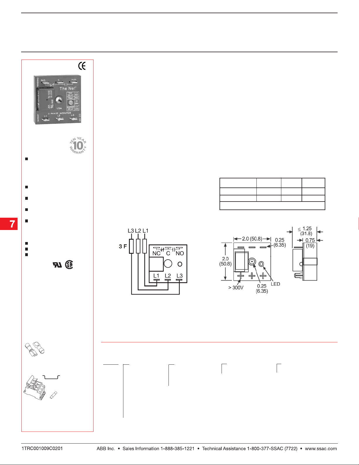
Relay contacts are isolated. Dashed lines are
internal connections.
F = 2A Fast Acting Fuses are recommended,
but not required.
L1 = Phase A L2 = Phase B L3 = Phase C
NO = Normally Open NC = Normally Closed
C = Common, Transfer Contact
OrOr
dering Tdering T
Or
dering T
OrOr
dering Tdering T
TVM TVM
TVM
TVM TVM
SeriesSeries
Series
SeriesSeries
Example P/N:Example P/N:
Example P/N:
Example P/N:Example P/N:
ableable
able
ableable
XX
X
XX
Line VLine V
oltageoltage
Line V
oltage
Line VLine V
oltageoltage
208 A208 A
–
208 A - 208 V AC
208 A208 A
220 A220 A
–
220 A - 220 V AC
220 A220 A
230 A230 A
–
230 A - 230 V AC
230 A230 A
240 A240 A
–
240 A - 240 V AC
240 A240 A
380 A380 A
–
380 A - 380 V AC
380 A380 A
400 A400 A
–
400 A - 400 V AC
400 A400 A
415 A415 A
–
415 A - 415 V AC
415 A415 A
440 A440 A
–
440 A - 440 V AC
440 A440 A
460 A460 A
–
460 A - 460 V AC
460 A460 A
480 A480 A
–
480 A - 480 V AC
480 A480 A
TVM240A45S10STVM240A45S10S
TVM240A45S10S
TVM240A45S10STVM240A45S10S
XX
X
XX
VV
oltage Unbalanceoltage Unbalance
V
oltage Unbalance
VV
oltage Unbalanceoltage Unbalance
Specify Fixed
Percentage
44
55
66
77
5,
55
6,
66
7,
77
1010
10
1010
88
8,
88
–
4,
44
9 9
9, or
9 9
Inches (Millimeters)
XX
X
XX
TT
rip Delayrip Delay
T
rip Delay
TT
rip Delayrip Delay
–Specify Fixed Delay
In Seconds (
0.20.2
[
0.2 ...
0.20.2
SS
S)
SS
11
1]
11
In 0.1 s Increments
11
100100
[
1 ...
100]
11
100100
In 1 s Increments
XX
X
XX
Restart DelayRestart Delay
Restart Delay
Restart DelayRestart Delay
–Specify Fixed Delay
In Seconds (
0.40.4
[
0.4 ...
0.40.4
In 0.1 s Increments
11
[
1 ...
11
In 1 s Increments
In Minutes (
11
[
1 ...
11
In 1 M Increments
Low Voltage Products & Systems7.20
100100
100]
100100
999999
999]
999999
SS
S)
SS
11
1]
11
MM
M)
MM
TVM02B01 01.20 .0 5
Compact 3 Phase VCompact 3 Phase V
Compact 3 Phase V
Compact 3 Phase VCompact 3 Phase V
TVM Series The Net
oltage Monitoroltage Monitor
oltage Monitor
oltage Monitoroltage Monitor
TM
Motor Protector
Technical Data Technical Data
Technical Data
Technical Data Technical Data
Line VLine V
oltageoltage
Line V
oltage
Line VLine V
oltageoltage
Type
Input Voltage 208 ... 480 V AC (See Ordering Table)
Line Frequency 50 ... 100 Hz
Phase Sequence ABC
Power Consumption Approx. 2 W for 240 V units
Overvoltage, Undervoltage, &Overvoltage, Undervoltage, &
Overvoltage, Undervoltage, &
Overvoltage, Undervoltage, &Overvoltage, Undervoltage, &
VV
oltage Unbalanceoltage Unbalance
V
oltage Unbalance
VV
oltage Unbalanceoltage Unbalance
Overvoltage & Undervoltage Voltage detection with delay trip & automatic reset
Undervoltage Trip Point 88 ... 92% of the selected line voltage
Reset Voltage ≅ +3% of trip voltage
Overvoltage Trip Point 109 ... 113% of the selected line voltage
Reset Voltage ≅ -3% of trip voltage
Trip Variation vs Temperature ≤ +/-2%
Voltage Unbalance Factory fixed, from 4 ... 10%
Reset On Balance ≅ -0.7% unbalance
Trip Delay Range Fixed, from 0.2 ... 100 s, +/-15% or +/-0.1 s, whichever is greater
Restart Delay Range Fixed, from 0.4 s ... 999 m, +/-15% or +/-0.1 s, whichever is greater
Phase Reversal &Phase Reversal &
Phase Reversal &
Phase Reversal &Phase Reversal &
Phase Loss Response Phase Loss Response
Phase Loss Response ≤ 200 ms; automatic reset
Phase Loss Response Phase Loss Response
Phase Loss ≥ 25% unbalance
OutputOutput
Output
OutputOutput
Type Isolated SPDT relay contacts
Rating 208 ... 240 V AC (55°C) 10 A resistive @ 125 V AC, 5 A @ 250 V AC, 1/4 hp @ 125 V AC
380 ... 480 V AC 10 A resistive @ 240 V AC, 1/4 hp @ 125 V AC,
Life Mechanical--1 x 10⁶; Electrical --1 x 10
ProtectionProtection
Protection
ProtectionProtection
Surge IEEE C62.41-1991 Level B
Dielectric Breakdown 208 ... 240 V AC ≥ 1500 V RMS input to output terminals
380 ... 480 V AC ≥ 2500 V RMS input to output terminals
MechanicalMechanical
Mechanical
MechanicalMechanical
Mounting Surface mount with one #8 (M5 x 0.8) screw
Termination 0.25 in. (6.35 mm) male quick connect terminals
EnvironmentalEnvironmental
Environmental
EnvironmentalEnvironmental
Storage Temperature -40°C ... +85°C
Humidity 95% relative, non-condensing
Weight ≅ 2.8 oz (79 g)
Three phase Delta or Wye with no connection to neutral
Approx. 3 W for 480 V units
1/3 hp @ 250 V AC; max. voltage 277 V AC
5
Operating TOperating T
Operating T
Operating TOperating T
emperaturemperatur
emperatur
emperaturemperatur
ee
e
ee
ConnectionConnection
Connection
AccessoryAccessory
Accessory
AccessoryAccessory
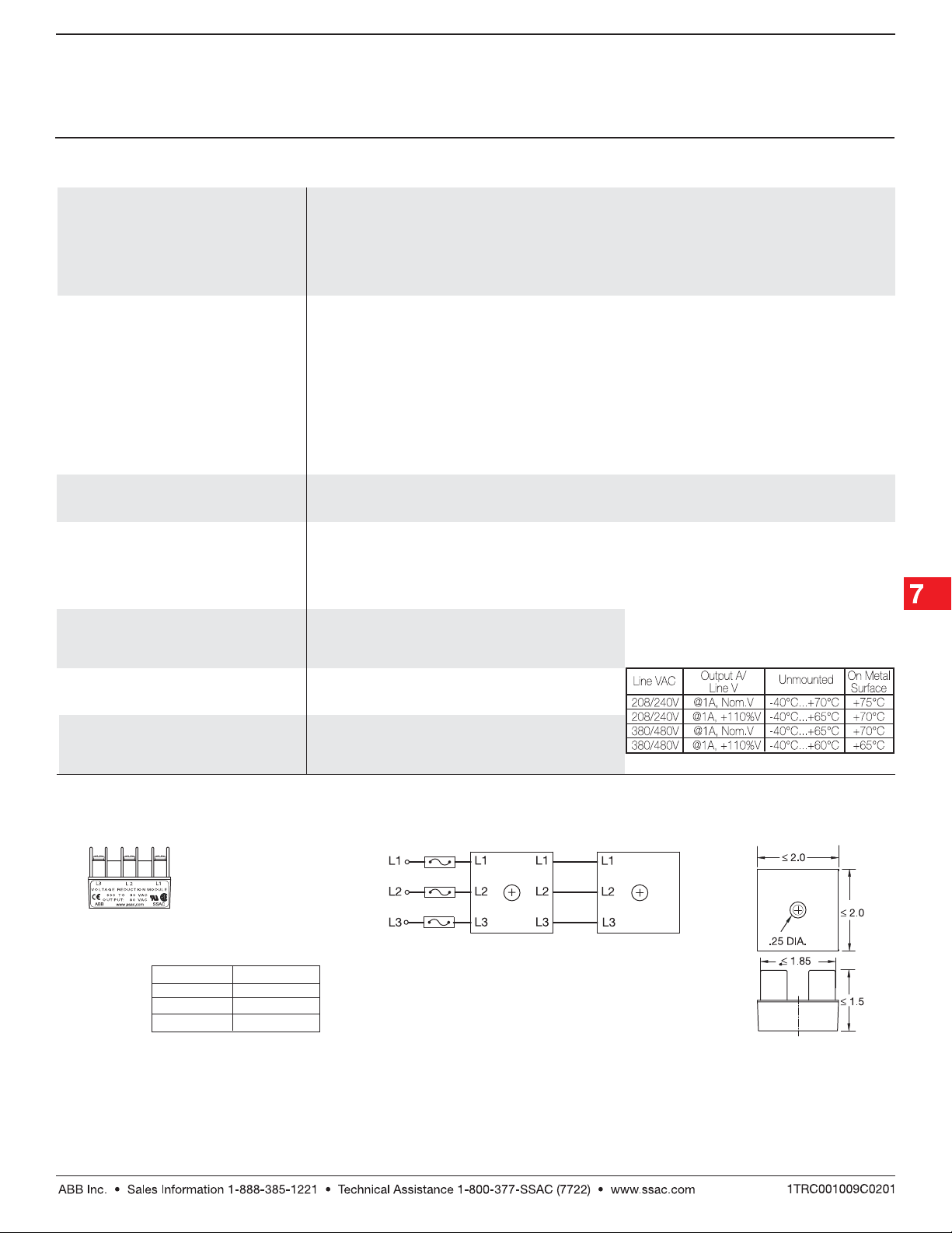
VRM VVRM V
VRM V
VRM VVRM V
The VRM6048 Accessory Module
allows the TVM9XXX to monitor a 3-Phase
550 ... 600 V AC Line.
TVM02B01 01.20 .0 5
Low Voltage Products & Systems 7.21
oltage Reduction Moduleoltage Reduction Module
oltage Reduction Module
oltage Reduction Moduleoltage Reduction Module
VRM6048VRM6048
P/N:
VRM6048
VRM6048VRM6048
Voltage:
Package: Molded Housing with Encapsulated
Mounting: Surface Mount with One #10 (M5 x 0.8)
Termination: Screw Terminals with Captive Wire
INPUT *OUTPUT
600 V AC 480 V AC
575 V AC 460 V AC
550 V AC 440 V AC
Circuitry
Plastic Screw. May be DIN Rail
Mounted Using P1023-20 Adaptor
Clamps for up to No.12 AWG Wire.
ConnectionConnection
575 V AC → 460 V AC
VRM Module
VRM6048VRM6048
P/N:
VRM6048
VRM6048VRM6048
* The VRM6048 must be connected as shown. If the
TVM9XXX is disconnected, the VRM output voltage
equals the input voltage.
Adjustment: If the measured line voltage is 575 V
AC, connect as shown and adjust the TVM9XXX
for 460 V AC operation.
Operating: -40°C to +70°C
Storage: -40°C to + 85°C
Humidity: 95% Relative, Non-Condensing
Voltage Monitor
TVM9XXXX
Mechanical View Mechanical View
Mechanical View
Mechanical View Mechanical View
Inches (Millimeters)
 Loading...