

SSAC TSD7 Series Catalog Page
Two Terminal Series
Connection to Load
Fixed or Adjustable
Delays From 1 s ... 1000 m
Digital Integrated Circuitry
+/-0.5% Repeat Accuracy
Approvals:
AccessoriesAccessories
Accessories
AccessoriesAccessories
BB
B
BB
External adjust
potentiometer
AA
A
AA
P/Ns:
P1004-13 P1004-13
P1004-13 (fig A)
P1004-13 P1004-13
P1004-13-X P1004-13-X
P1004-13-X (fig B)
P1004-13-X P1004-13-X
Female quick
connect
P/N:
P1015-64P1015-64
P1015-64
P1015-64P1015-64
(AWG 14/16)
Interval or Delay On BreakInterval or Delay On Break
Interval or Delay On Break
Interval or Delay On BreakInterval or Delay On Break
TSD7 Series
Timing Module
DescriptionDescription
Description
DescriptionDescription
The TSD7 utilizes only two terminals connected in series with the load. Interval timing mode period is achieved
by using a small portion of the AC sine wave allowing sufficient voltage for circuit operation. It can be used as
an interval timer to control or pulse shape the operation of contactors, solenoids, relays, and lamp loads. The
TSD7 can be wired to delay on the break of a switch for energy saving fan delays.
ConnectionConnection
Connection
OperationOperation
Operation
OperationOperation
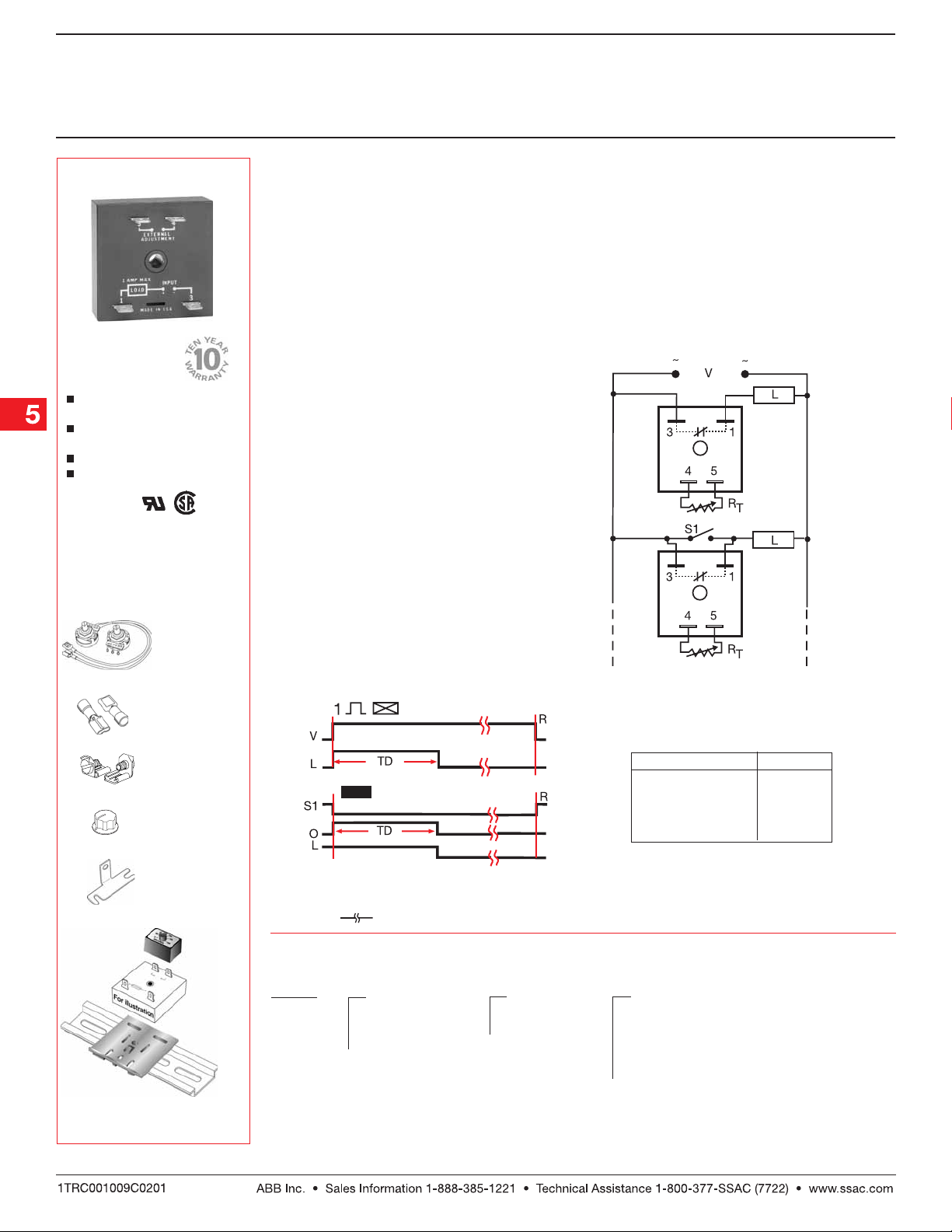
Interval --Interval --
Interval --
Interval --Interval --
Upon application of input voltage, the output
energizes and the time delay begins. The output
remains energized throughout the time delay. At the
end of the time delay, the output de-energizes and
remains de-energized until power is removed.
Reset:Reset:
Reset: Removing input voltage resets the time delay
Reset:Reset:
and the output.
Delay On Break -- Delay On Break --
Delay On Break -- Upon closure of SW1, the load is
Delay On Break -- Delay On Break --
energized and the timer is reset (zero volts across its
input terminals). Opening SW1 re-applies input voltage
to the timer, the load remains energized and the time
delay begins. At the end of the time delay, the output
de-energizes. If SW1 is open when power is applied,
the load will energize for the time delay then deenergize.
Reset:Reset:
Reset: Reclosing SW1 resets the timer.
Reset:Reset:
FunctionFunction
Function
FunctionFunction
Interval
ConnectionConnection
Interval
Delay On
Break
V = Voltage L = Load S1 = Initiate Switch
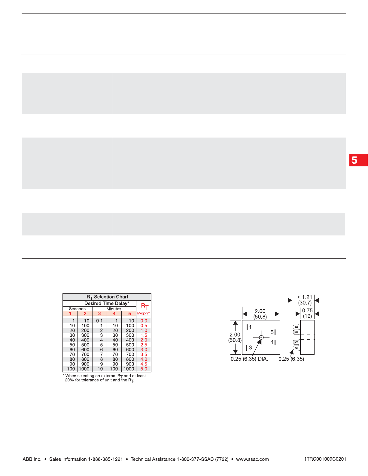
RT is used when external adjustment is
ordered. Dashed lines are internal connections.
Quick connect to
screw adaptor
P1015-18 P1015-18
P/N:
P1015-18
P1015-18 P1015-18
Versa-knob
P0700-7 P0700-7
P/N:
P0700-7
P0700-7 P0700-7
Mounting bracket
P1023-6 P1023-6
P/N:
P1023-6
P1023-6 P1023-6
Plug-on
adjustment
module
VTP(X)(X) VTP(X)(X)
P/N:
VTP(X)(X)
VTP(X)(X) VTP(X)(X)
DIN rail P/Ns:
017322005017322005
017322005 (St eel)
017322005017322005
C103PM C103PM
C103PM (Al)
C103PM C103PM
→
DIN rail adaptor
P1023-20 P1023-20
P/N:
P1023-20
P1023-20 P1023-20
See accessory pages for
specifications.
←
Delay On Break
V = Voltage L = Load S1 = Initiate Switch
R = Reset TD = Time Delay O = Output
= Undefined time
OrOr
dering Tdering T
Or
dering T
OrOr
dering Tdering T
TSD7 TSD7
TSD7
TSD7 TSD7
SeriesSeries
Series
SeriesSeries
Example P/N:Example P/N:
Example P/N:
Example P/N:Example P/N:
ableable
able
ableable
X X
X
X X
InputInput
Input
InputInput
22
–
2 - 24 V AC
22
4 4
–
4 - 120 V AC
4 4
66
–
6 - 230 V AC
66
TSD7221 TSD7221
TSD7221 Fixed –
TSD7221 TSD7221
TSD7410.5MTSD7410.5M
TSD7410.5M
TSD7410.5MTSD7410.5M
X X
X
X X
AdjustmentAdjustment
Adjustment
AdjustmentAdjustment
1 1
–
1 - Fixed
1 1
22
–
2 - External
22
Adjust
Time Delay VTP P/N
11
1 – 1 ... 100 s
11
22
2 – 10 ... 1000 s
22
33
3 – 0.1 ... 10 m
33
44
4 – 1 ... 100 m
44
55
5 – 10 ... 1000 m
55
VTP5G
VTP5K
VTP5N
VTP5P
VTP5R
Selection Table for VTP Plug-on Adjustment
Accessory.
X X
X
X X
Time DelayTime Delay
Time Delay *
Time DelayTime Delay
1 1
–
1 - 1 ... 100 s
1 1
2 2
–
2 - 10 ... 1000 s
2 2
33
–
3 - 0.1 ... 10 m
33
4 4
–
4 - 1 ... 100 m
4 4
55
–
5 - 10 ... 1000 m
55
*If Fixed Delay is selected,
insert delay [
followed by (
0.10.1
[
0.1 ...
0.10.1
10001000
1000] (
10001000
11
10001000
1...
1000]
11
10001000
SS
S) sec. or
SS
MM
M) min.
MM
Low Voltage Products & Systems5.150
TSD72B01 12.28 . 0 4
Interval or Delay On BreakInterval or Delay On Break
Interval or Delay On Break
Interval or Delay On BreakInterval or Delay On Break
TSD7 Series
Timing Module
Technical Data Technical Data
Technical Data
Technical Data Technical Data
Time DelayTime Delay
Time Delay
Time DelayTime Delay
Type Digital integrated circuitry
Range 1 s ... 1000 m in 5 adjustable ranges or fixed
Repeat Accuracy +/-0.5% or 20 ms, whichever is greater
Tolerance (Factory Calibration) ≤ +/-10%
Recycle Time ≤ 400 ms
Time Delay vs. Temperature & Voltage ≤ +/-2%
InputInput
Input
InputInput
Voltage 24, 120, or 230 V AC
Tolerance +/-20%
Line Frequency 50 ... 60 Hz
OutputOutput
Output
OutputOutput
Type Solid state
Form Normally Open, closed during timing
Maximum Load Current 1 A steady state, 10 A inrush at 45°C
Minimum Load Current 40 mA
Effective Voltage Drop (VLine-VLoad)
ProtectionProtection
Protection
ProtectionProtection
Circuitry Encapsulated
Dielectric Breakdown ≥ 2000 V RMS terminals to mounting surface
Insulation Resistance ≥ 100 MΩ
MechanicalMechanical
Mechanical
MechanicalMechanical
Mounting Surface mount with one #10 (M5 x 0.8) screw
Package 2 x 2 x 1.21 in. (50.8 x 50.8 x 30.7 mm)
Termination 0.25 in. (6.35 mm) male quick connect terminals
EnvironmentalEnvironmental
Environmental
EnvironmentalEnvironmental
Operating/Storage Temperature -40°C ... +75°C / -40°C ... +85°C
Humidity 95% relative, non-condensing
Weight ≅ 2.4 oz (68 g)
Input Input
Input
Input Input
24 V AC 3 V
120 V AC 4 V
230 V AC 6 V
Effective DropEffective Drop
Effective Drop
Effective DropEffective Drop
External Resistance vs Time DelayExternal Resistance vs Time Delay
External Resistance vs Time Delay
External Resistance vs Time DelayExternal Resistance vs Time Delay
TSD72B01 12.28 . 0 4
Low Voltage Products & Systems 5.151
Mechanical ViewMechanical View
Mechanical View
Mechanical ViewMechanical View
Inches (Millimeters)
 Loading...