

SSAC TSB Series Catalog Page
Delay On Break (Release)Delay On Break (Release)
Delay On Break (Release)
Delay On Break (Release)Delay On Break (Release)
TSB Series
Timing Module
DescriptionDescription
Description
DescriptionDescription
The TSB Series is a totally solid state delay on break timing module. The TSB is available with a fixed, external,
or onboard adjustable time delay. Time Delays from .05 to 600 seconds, in 4 standard ranges, cover over 90%
of all OEM and commercial appliance timing applications. The repeat accuracy is +/-2%. Operating voltages
of 24,120, or 230 V AC are available. The TSB's 1A steady state, 10A rated solid state output is perfect for
direct control of solenoids, contactors, relays, lamps, buzzers, and small heaters. The TSB can be surface
mounted with a single screw, or snapped on 35 mm DIN rail using the P1023-20 adaptor.
Totally Solid State
Encapsulated
Fixed or Adjustable
Delays From 0.05 ... 600 s in
4 Ranges
+/- 2% Repeat Accuracy
+/-5% Factory Calibration
Approvals:
AccessoriesAccessories
Accessories
AccessoriesAccessories
BB
B
BB
External adjust
potentiometer
AA
A
AA
P/Ns:
P1004-95P1004-95
P1004-95
P1004-95P1004-95
P1004-95-X P1004-95-X
P1004-95-X (fig B)
P1004-95-X P1004-95-X
Mounting bracket
P/N:
Female quick
connect
P/N
P1015-64P1015-64
P1015-64
P1015-64P1015-64
P1023-6 P1023-6
P1023-6
P1023-6 P1023-6
::
:
::
(fig A)
(AWG 14/16)
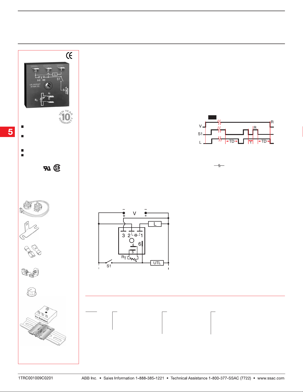
OperationOperation
Operation
OperationOperation
Input voltage must be applied before and during
timing. Upon closure of the initiate switch, the output
energizes. The time delay begins when the initiate
switch opens. The output remains energized during
timing. At the end of the time delay, the output deenergizes. The output will energize if the initiate switch
is closed when input voltage is applied.
Reset:Reset:
Reset: Reclosing the initiate switch during timing
Reset:Reset:
resets the time delay . Loss of input voltage r esets the
output and the time delay.
ConnectionConnection
Connection
ConnectionConnection
FunctionFunction
Function
FunctionFunction
Delay On Break
V = Voltage L = Load S1 = Initiate Switch
TD = Time Delay R = Reset
t = Incomplete Time Delay
= Undefined time
Quick connect to
screw adaptor
P1015-18 P1015-18
P/N:
P1015-18
P1015-18 P1015-18
Versa-knob
P0700-7 P0700-7
P/N:
P0700-7
P0700-7 P0700-7
DIN rail P/Ns:
017322005 017322005
017322005 (Stee l)
017322005 017322005
C103PM C103PM
C103PM (Al)
C103PM C103PM
→
DIN rail adaptor
P1023-20 P1023-20
P/N:
P1023-20
P1023-20 P1023-20
See accessory pages for
specifications.
←
RT is used when external adjustment is ordered.
Dashed lines are internal connections.
S1 = Initiate Switch UTL = Optional Untimed Load
L = Load
OrOr
dering Tdering T
Or
dering T
OrOr
dering Tdering T
TSB TSB
TSB
TSB TSB
SeriesSeries
Series
SeriesSeries
ableable
able
ableable
X X
X
X X
––
–
––
––
–
––
––
–
––
InputInput
Input
InputInput
22
2
22
44
4
44
66
6
66
--
- 24 V AC
--
- -
- 120 V AC
- -
- -
- 230 V AC
- -
X X
X
X X
Adjustment Adjustment
Adjustment
Adjustment Adjustment
– –
–
– –
– –
–
– –
11
- -
1
-
11
- -
22
- -
2
-
22
- -
Fixed
External
Adjust
––
33
- -
–
3
-
––
33
- -
Onboard
Adjust
Example P/N:Example P/N:
Example P/N:
Example P/N:Example P/N:
TSB422TSB422
TSB422 Fixed –
TSB422TSB422
TSB410.5 TSB410.5
TSB410.5
TSB410.5 TSB410.5
X X
X
X X
Time Delay* Time Delay*
Time Delay*
Time Delay* Time Delay*
– –
–
– –
– –
–
– –
– –
–
– –
1 1
--
1
-
1 1
--
0.05 ... 3 s
22
- -
2
-
22
- -
0.5 ... 60 s
33
- -
3
-
33
- -
2 ... 180 s
––
44
--
–
4
-
––
44
--
5 ... 600 s
* If Fixed Delay is selected, insert
0.050.05
0.05
0.050.05
...
600600
600] in seconds.
600600
delay [
Low Voltage Products & Systems5.76
TSBGen 07.0 2 . 0 4

Delay On Break (Release)Delay On Break (Release)
Delay On Break (Release)
Delay On Break (Release)Delay On Break (Release)
TSB Series
Timing Module
Technical Data Technical Data
Technical Data
Technical Data Technical Data
Time DelayTime Delay
Time Delay
Time DelayTime Delay
Range 0.05 s ... 600 s in 4 adjustable ranges or fixed
Repeat Accuracy +/-2% or 20 ms, whichever is greater
Tolerance (Factory Calibration) ≤ +/-5%
Time Delay vs. Temperature & Voltage ≤ +/-10%
Reset Time ≤
InputInput
Input
InputInput
Voltage 24, 120, or 230 V AC
Tolerance +/-20%
Line Frequency 50 ... 60 Hz
Power Consumption ≤ 2 VA
OutputOutput
Output
OutputOutput
Type Solid state
Form Normally Open, closed before & during timing
Maximum Load Current 1 A steady state, 10 A inrush at 60°C
Off State Leakage Current ≅ 5 mA at 230 V AC
Voltage Drop ≅ 2.5 V at 1 A
ProtectionProtection
Protection
ProtectionProtection
Circuitry Encapsulated
Dielectric Breakdown ≥ 2000 V RMS terminals to mounting surface
Insulation Resistance ≥ 100 MΩ
MechanicalMechanical
Mechanical
MechanicalMechanical
Mounting Surface mount with one #10 (M5 x 0.8) screw
Package 2 x 2 x 1.21 in. (50.8 x 50.8 x 30.7 mm)
Termination 0.25 in. (6.35 mm) male quick connect terminals
EnvironmentalEnvironmental
Environmental
EnvironmentalEnvironmental
Operating Temperature -40°C ... +75°C
Storage Temperature -40°C ... +85°C
Humidity 95% relative, non-condensing
Weight ≅ 2.4 oz (68 g)
150 ms
Mechanical View Mechanical View
Mechanical View
Mechanical View Mechanical View
Fixed & External AdjustFixed & External Adjust
Fixed & External Adjust
Fixed & External AdjustFixed & External Adjust
Onboard AdjustOnboard Adjust
Onboard Adjust
Onboard AdjustOnboard Adjust
TSBGen 07.0 2 . 0 4
Inches (Millimeters)
Low Voltage Products & Systems 5.77
 Loading...