

SSAC TL Series Catalog Page
Lockout TimerLockout Timer
Lockout Timer
Lockout TimerLockout Timer
TL Series
HVAC/R Timer
DescriptionDescription
Description
DescriptionDescription
The TL Series provides protection against short cycling of a compressor. At the end of each operation, or
whenever power is lost, a lockout delay is initiated. This lockout delay prevents restarting of the compressor
until the head pressure has equalized. Compressor relay chatter due to thermostat bounce is eliminated by
use of optional one second delay on make. The TL Series should not be used with cooling anticipator resistors
or solid state switches. (See the TA Series).
Lockout Delay--Prevents
Short Cycling of a
Compressor
Optional 1 s Delay On Make
Prevents Contactor Chatter
Totally Solid State and
Encapsulated
24 V AC ... 230 V AC in 3
Ranges
Eliminates Nuisance Service
Calls Due to Blown Fuse or
Tripped Breakers
Approvals:
AccessoriesAccessories
Accessories
AccessoriesAccessories
Female quick connect
P/N:
P1015-64 P1015-64
P1015-64
(AWG 14/16)
P1015-64 P1015-64
OperationOperation
Operation
OperationOperation
Lockout: Lockout:
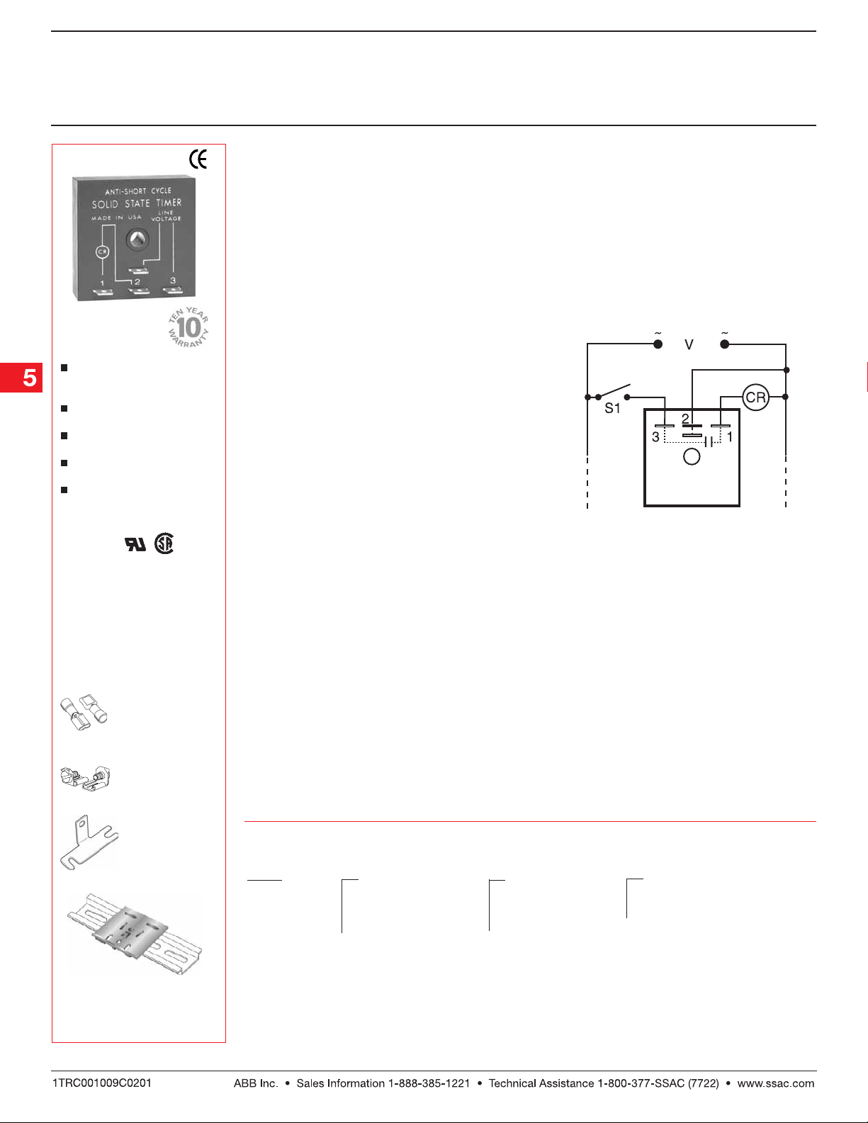
Lockout: On initial closure of S1, the compressor
Lockout: Lockout:
relay energizes immediately (or after an optional 1 s
delay). When the S1 opens or input voltage is
interrupted, the output opens and remains open for
the lockout time delay. During this lockout time delay
period, the compressor relay cannot be re-energized.
Reset:Reset:
Reset: The lockout time delay cannot be reset. After
Reset:Reset:
the time delay is completed, the unit automatically
resets.
ConnectionConnection
Connection
ConnectionConnection
V = Voltage S1 = Initiate Switch
CR = Compressor or Control Relay
Quick connect to
screw adaptor
P1015-18 P1015-18
P/N:
P1015-18
P1015-18 P1015-18
Mounting bracket
P1023-6 P1023-6
P/N:
P1023-6
P1023-6 P1023-6
DIN rail P/Ns:
017322005 017322005
017322005 (Steel)
017322005 017322005
C103PM C103PM
C103PM (Al )
C103PM C103PM
→
DIN rail adaptor
P1023-20 P1023-20
P/N:
P1023-20
P1023-20 P1023-20
See accessory pages for
specifications.
←
OrOr
dering Tdering T
Or
dering T
OrOr
dering Tdering T
TL TL
TL
TL TL
SeriesSeries
Series
SeriesSeries
Example P/N:Example P/N:
Example P/N:
Example P/N:Example P/N:
ableable
able
ableable
XX
X
XX
InputInput
Input
InputInput
24 A 24 A
–
24 A - 24 V AC
24 A 24 A
120 A 120 A
–
120 A - 120 V AC
120 A 120 A
230 A 230 A
–
230 A - 230 V AC
230 A 230 A
TL24A2TTL24A2T
TL24A2T
TL24A2TTL24A2T
, TL120A5, TL120A5
, TL120A5
, TL120A5, TL120A5
XX
X
XX
Lockout TimeLockout Time
Lockout Time
Lockout TimeLockout Time
22
–
2 m
22
33
–
3 m
33
55
–
5 m
55
XX
X
XX
Delay On MakeDelay On Make
Delay On Make
Delay On MakeDelay On Make
(Blank) No delay
T T
–
T - 1 s
T T
Low Voltage Products & Systems5.228
TL002B01 01.05.05
Lockout TimerLockout Timer
Lockout Timer
Lockout TimerLockout Timer
TL Series
HVAC/R Timer
Technical Data Technical Data
Technical Data
Technical Data Technical Data
InputInput
Input
InputInput
Voltage 24, 120, or 230 V AC, 50 ... 60 Hz
Tolerance +/-20%
OutputOutput
Output
OutputOutput
Minimum Load Current ≤ 40 mA
Maximum Load Current 1 A at 24 V AC; 0.5 A at 120 & 230 V AC at 60°C
Inrush Current 10 A at 60°C
Voltage Drop 24 V AC-- 2.5 V at 1 A
Time DelayTime Delay
Time Delay
Time DelayTime Delay
Initiate Time ≅ 8 ms
Lockout Time* Fixed 2, 3, or 5 m
Tolerance -15% ... +35%
Option 1 s Delay on make eliminates contactor
ProtectionProtection
Protection
ProtectionProtection
Circuitry Encapsulated
Dielectric Breakdown ≥ 2000 V RMS terminals to mounting surface
Insulation Resistance ≥ 100
120 & 230 V AC -- 4.2 V at 0.5 A
chatter due to thermostat bounce
MΩ
MechanicalMechanical
Mechanical
MechanicalMechanical
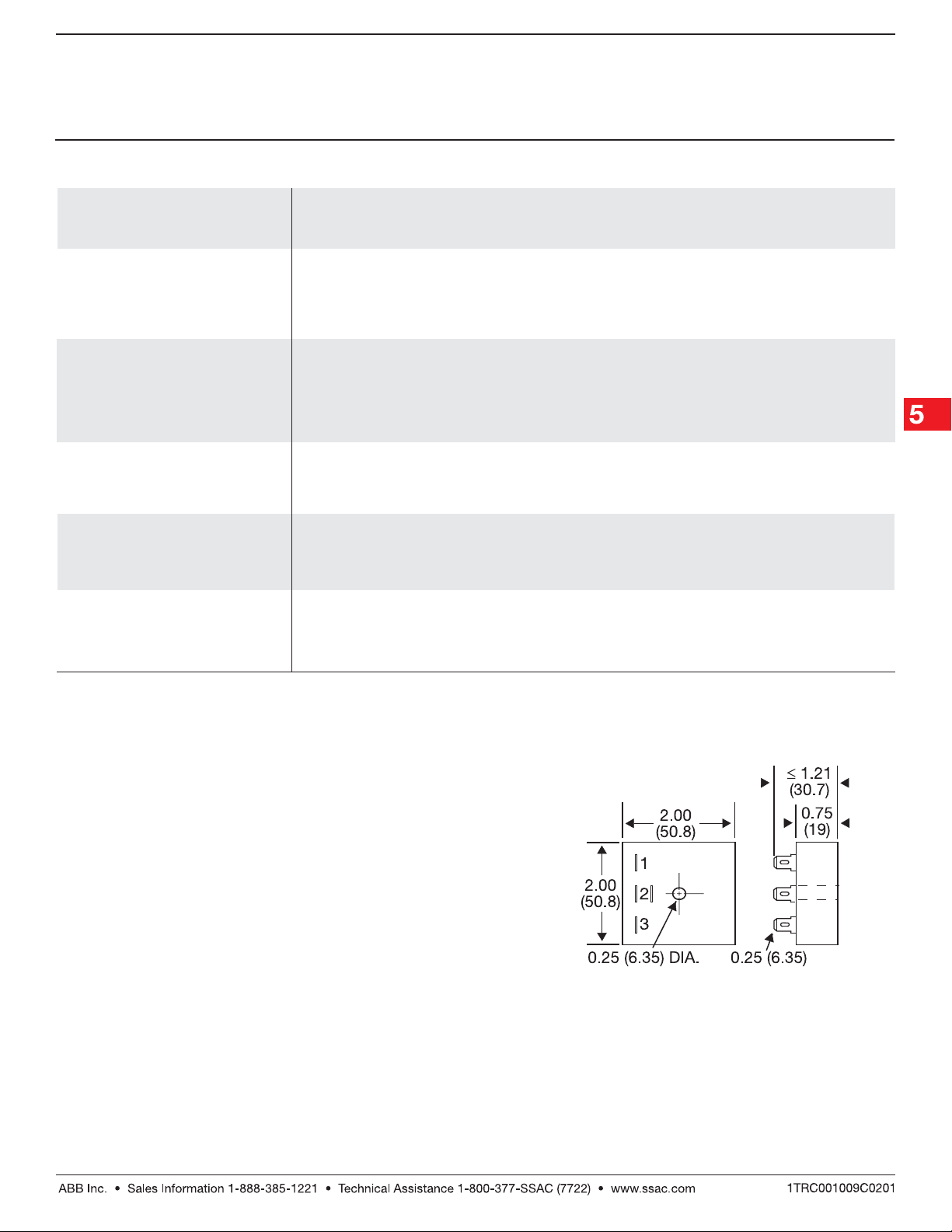
Mounting Surface mount with one #10 (M5 x 0.8) screw
Package 2 x 2 x 1.21 in. (50.8 x 50.8 x 30.7 mm)
Termination 0.25 in. (6.35 mm) male quick connect terminals
EnvironmentalEnvironmental
Environmental
EnvironmentalEnvironmental
Operating Temperature -40°C ... +70°C
Storage Temperature -40°C ... +85°C
Humidity 95% relative, non-condensing
Weight ≅ 2.4 oz (68 g)
*Power must be applied for at least 15 s to achieve a full lockout delay.
Less than 15 s will result in proportionally shorter delay periods.
NOTE: Cooling anticipator resistor or leakage may cause erratic
operation. See TA Series for use with 24 V AC systems that include
anticipator resistors or use solid state switches.
Mechanical View Mechanical View
Mechanical View
Mechanical View Mechanical View
Inches (Millimeters)
TL002B01 01.05.05
Low Voltage Products & Systems 5.229
 Loading...