

S.R.Smith TYPHOON Assembly And Installation Instructions Manual
TYPHOON
ASSEMBLY AND INSTALLATION
INSTRUCTIONS
WESTERN SALES AND MANUFACTURING PLANT
Phone: (503) 266-2231 • Fax: (503) 266-4334
06-714 ©S.R. SMITH, LLC 2006 MAR 08
CORPORATE HEADQUARTERS
P.O. Box 400 • 1017 SW Berg Parkway
Canby, Oregon 97013
www.srsmith.com
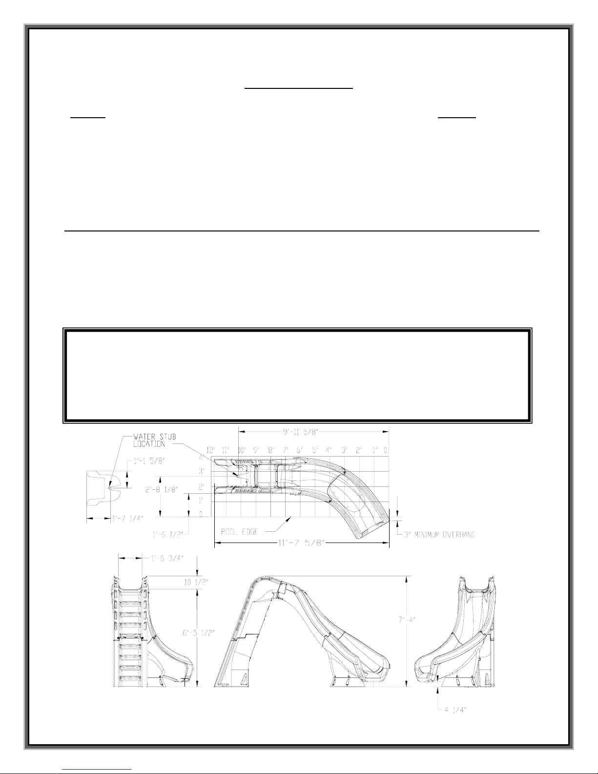
Table of Contents
Topic Page #
Introduction………………………………………………………………………………………… 2
Parts List…………………………………………………………………………… ………………. 3
Assembly Instructions…………………………………………………………………………….. 4
Manufacturer’s Placement Instructions………………………………………………… ………. 12
Installed Slides’ Structural & Installation Checklist…………………………………………….. 14
INTRODUCTION
THE TYPHOON SLIDE IS DESIGNED AND MANUFACTURED FOR INSTALLATION AND USE ON
INGROUND SWIMMING POOLS ONLY. TYPHOON SLIDES ARE NEVER TO BE INSTALLED AND
USED ON HOUSEBOATS, BOAT DOCKS, FLOATING DOCKS OR PLATFORMS, OR OTHER
BODIES OF WATER SUCH AS LAKES, PONDS, RIVERS, ETC. PROPER AND COMPLETE
ASSEMBLY, USE AND SUPERVISION IS ESSENTIAL FOR PROPER OPERATION AND TO REDUCE
THE RISK OF ACCIDENT OR INJURY.
**IMPORTANT**
Check inside all boxes and packaging materials for parts. Before beginning assembly, read the
instructions and identify parts using the figures and parts listed in this document. It is critical that all
parts be carefully inspected by the installer prior to installation to ensure that no damage occurred in
transit and that a damaged part is not used. Proper installation cannot be overstressed, as an improper
installation voids S.R. Smith’s warranty and may affect the safety of the user.
FIG. 1
2
(15)
(13)
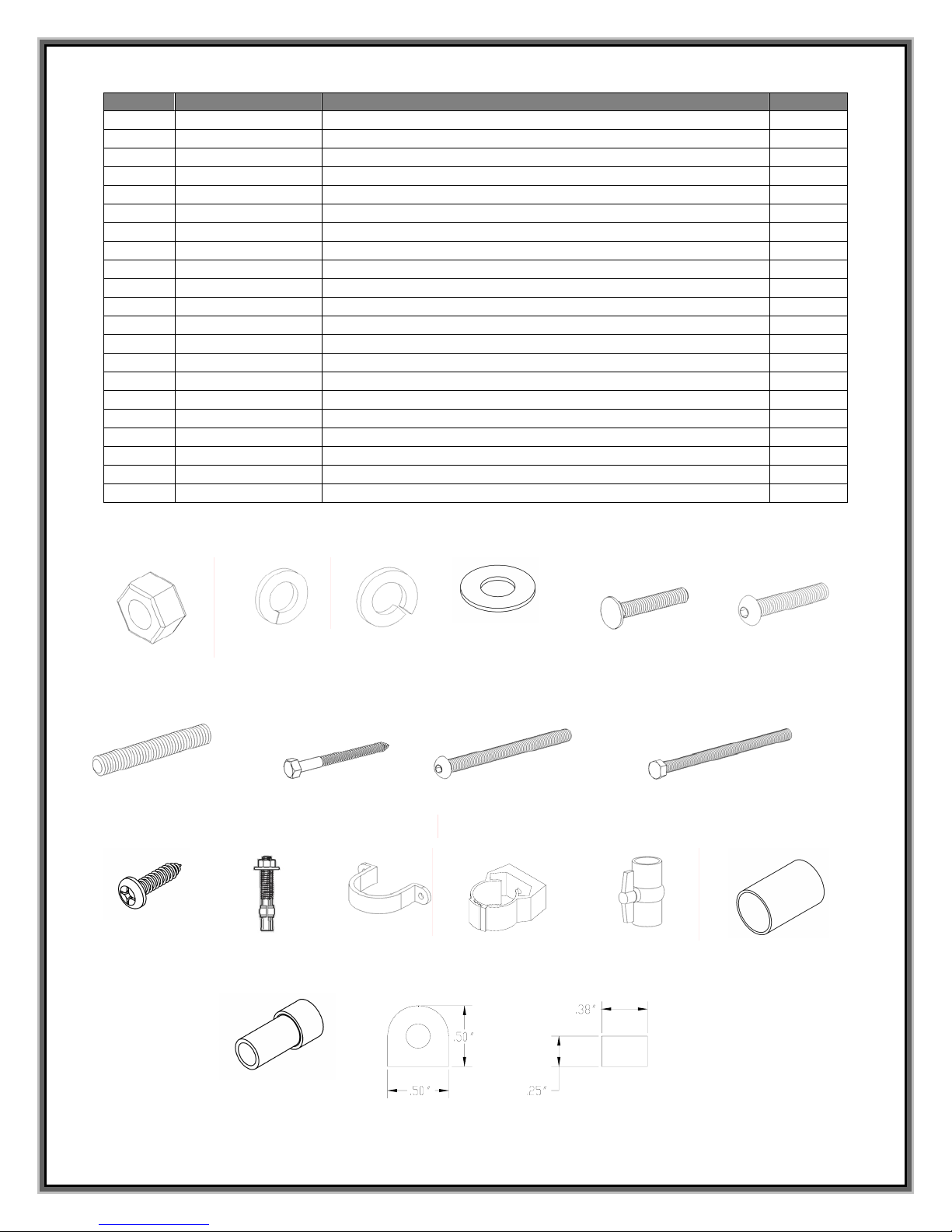
ITEM # PART # DESCRIPTION QTY.
1 5-139 3/8” Hex Nut 10 ea.
2 5-151 3/8” Lock Washer 10 ea.
3 05-14-115 1/2" Lock Washer 8 ea.
4 5-145 3/8” Flat Washer 24 ea.
5 5-246 3/8” x 2-3/4” Carriage Bolt 2 ea.
6 5-247 3/8” x 3” Button Head Cap Screw 4 ea.
7 5-239 3/8” x 2-1/2” Stud 4 ea.
8 5-240 3/8” x 3-1/2” Lag Screw 6 ea.
t.
9 5-237 3/8” x 5” Button Head Cap Screw 2 ea.
10 5-248 3/8” x 3.5” Hex Head Cap Screw 2 ea.
11 5-242 #14" x 1” Pan Head Tapping Screw 6 ea.
12 5-241 1/2" x 5” Anchor Stud 8 ea.
13 05-782 1.5” PVC Pipe Strap 2 ea.
14 05-767 1” Pipe Clamp 2 ea.
15 05-770 1” Ball Valve Gray 1 ea.
16 05-784 1” Coupling 1 ea.
17 05-779 Garden Hose Adapter 1 ea.
18 8-532 .5" HIGH X .5” WIDE X 32” LONG RUBBER GASKET 1 ea.
19 8-531 .25” HIGH X .375” WIDE X 33” LONG RUBBER GASKET 1 ea.
20 05-786-1 1” PVC Flex Hose, 16” long (Not Shown) 1 ea.
21 05-786-2 1” PVC Flex Hose, 68” long (Not Shown) 1 ea.
TYPHOON PARTS LIST
(1)
(7)
(11)
(12)
(17)
(2)
(3)
(8)
(18)
(4)
(9)
(14)
(5) (6)
(10)
(16)
(19)
3
ASSEMBLY INSTRUCTIONS
Tools Required:
1. Ratchet handle
2. 9/16” deep socket
3. 9/16” wrench
4. 3/4" socket or wrench
5. 7/32” allen wrench
6. Phillips head screwdriver
7. 1/2" concrete drill bit
8. 1/4" drill bit
9. Power drill
10. PVC pipe primer & glue
11. Anti-seize
12. Saw to cut PVC pipe
13. Knife
14. Level
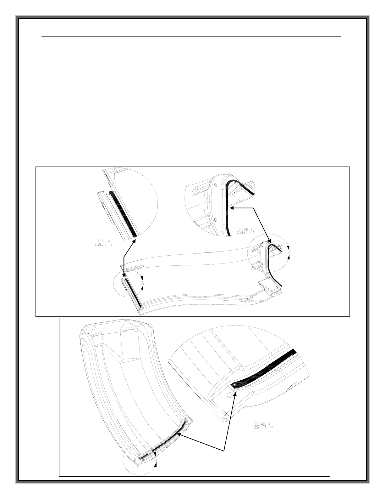
Gasket Installation:
• Gasket material has been applied at the factory for use at the connections/joints of the slide sections.
Additional gasket material has been supplied in case any gasket has fallen off during shipping.
• Apply gasket in the required locations as shown in the figures below.
• Place gasket along the section to determine the length needed.
• Cut gasket to appropriate length.
• Remove backing and adhere gasket to slide.
.5” TALL X .5” WIDE GASKET (18)
.25” TALL X .375” WIDE GASKET (19)
FIG 2: RUNWAY ENTRANCE
.5” TALL X .5” WIDE GASKET (18)
4
FIG 3: RUNWAY EXIT SECTION
(8)
(4)
Assembly:
Before getting started:
• To prevent damage to the parts during assembly, it is recommended that cardboard or
some other protective barrier is laid down on the ground where the slide is to be
assembled.
• Verify that the gasket material is affixed to the slide parts as shown in Figures 2 and 3.
• During assembly, be sure to apply a thin coat of anti-seize compound to the threads of all
fasteners. Anti-seize helps aid in assembly, prevents galling, and improves corrosion
resistance.
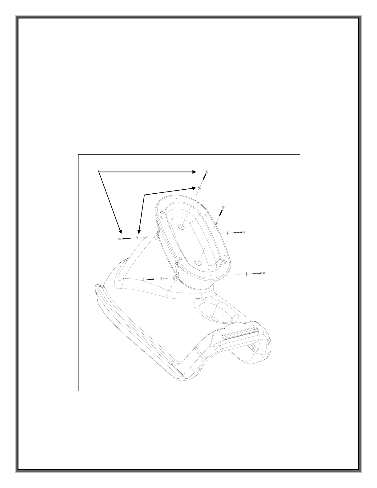
1) Assemble the pedestal part to the runway exit section as shown in Figure 4. Attach the pedestal part
to the runway exit section by inserting the two lag screws into the holes located in the bottom of the
pedestal.
2) Before inserting the lag bolts into the side of the runway exit part, 1/4” pilot holes must be drilled into
the center of each of the recesses. The pilot holes should be drilled through both the runway exit
section and into the pedestal.
3) Place the assembled run way exit section and pedestal upright so that the pedestal is resting on the
ground. Notes: It may take more than one person to perform this step. Verify that the gasket
material is properly attached before assembling the parts.
4) Insert the threaded studs into each of the threaded inserts as shown in Figure 5. The studs should be
screwed in by hand until they reach the bottom of the insert. If the studs cannot be threaded in by
hand, pliers may be used. Before using pliers, a piece of cloth should be placed over the stud to
protect the threads from damage. Note: Be sure to apply anti-seize to all fasteners to prevent
galling.
5
FIG. 4
 Loading...