

1/2 METER
FRONTIER II
JUMP STAND W/JIG
STEEL STAND COMPLETE
6’ 68-209-586 8’ 68-209-588
CAUTION
ALL MINIMUM WATER ENVELOPE DIMENSIONS FOR RESIDENTIAL INGROUND SWIMMING
POOLS MUST MEET THE ANSI/NSPI-5 2003 AMERICAN NATIONAL STANDARD FOR
RESIDENTIAL INGROUND SWIMMING POOLS (REFERENCED THROUGHOUT THESE
ASSEMBLY AND INSTALLATION INSTRUCTIONS AS “ANSI/NSP-5 2003”). COMPLY WITH
LOCAL GOVERNMENT REGULATIONS IF THEY EXCEED ANSI/NSPI STANDARDS.
All diving boards and related equipment are manufactured for inground swimming pools ONLY. The
S.R. Smith Frontier II Jump Stands are designed to be easily transported and installed. Follow all
instructions carefully and inspect closely to assure proper and safe installation.
PROPER INSTALLATION CANNOT BE OVERSTATED. IMPROPER INSTALLATION VOIDS S.R.
SMITH’S WARRANTY AND MAY AFFECT THE SAFETY OF THE USER.
ASSEMBLY AND INSTALLATION INSTRUCTIONS
– PLEASE READ CAREFULLY –
WESTERN SALES AND MANUFACTURING PLANT
CORPORATE HEADQUARTERS
P.O. Box 400 • 1017 S.W. Berg Parkway
Canby, Oregon 97013
Phone (503) 266-2231 • Fax (503) 266-4334
EASTERN MANUFACTURING PLANT
105 Challenger Drive
Portland, Tennessee 37148
Phone (615) 325-0770 • Fax (615) 325-0775
www.srsmith.com
ATTENTION!
THESE INSTRUCTIONS MUST REMAIN WITH STAND OWNER
06-305 AUG06
1/2 METER FRONTIER II JUMP STAND
For 6’ and 8’ Frontier II Jump Boards
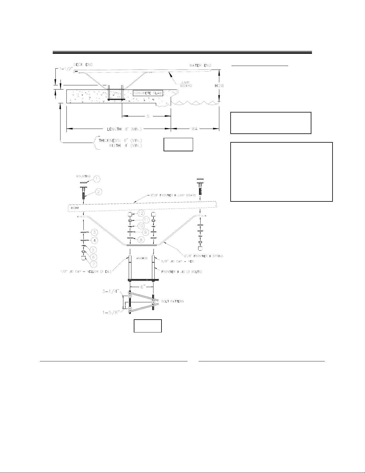
FIG. 1
TIGHTENING SCHEDULE
SECURE BOARD TO STAND WITH
MOUNTING HEX NUTS
FIBERGLASS: 20-25 FT-LBS.
SECURE STAND TO JIG WITH:
ANCHOR HEX NUTS
40-50 FT-LBS.
S.R. SMITH CANNOT GUARANTEE
CUSTOMER’S CONCRETE OR
THICKNESS
IMPORTANT NOTICE:
IT IS NECESSARY TO USE AN
ANTI-SEIZE COMPOUND ON
ALL STAINLESS STEEL
HARDWARE. FAILURE TO USE
ANTI-SEIZE COMPOUND MAY
RESULT IN GALLING AND
SEIZING OF THE HARDWARE.
FIG.2
FRONTIER II MOUNTING
BOLT KIT (69-209-032-SS)
1. STEP BOLT HEAD CAP – WHITE RUBBER (3 EA.)
2. 1/2” X 3” LG. STEP BOLT – S/S (3 EA.)
3. 1/2” X 1-1/2” ROUND NYLON WASHER (3 EA.)
4. 1/2” X 1-3/8” FLAT WASHER S/S (3 EA.)
5. 1/2” LOCK WASHER S/S (3 EA.)
6. 1/2” HEX NUT S/S (3 EA.)
7. 1/2” WHITE PLASTIC NUT CAP (3 EA.)
FRONTIER II SPRING
ANCHOR BOLT KIT (69-209-033-SS)
8. 5/8” X 1-3/4” NYLON PROTECTIVE WASHER (3 EA.)
9. 5/8” X 1-3/4” FLAT WASHER S/S (3 EA.)
10. 5/8” LOCK WASHER S/S (3 EA.)
11. 5/8” HEX NUT S/S (3 EA.)
12. 5/8” WHITE RUBBER NUT CAP (3 EA.)
2
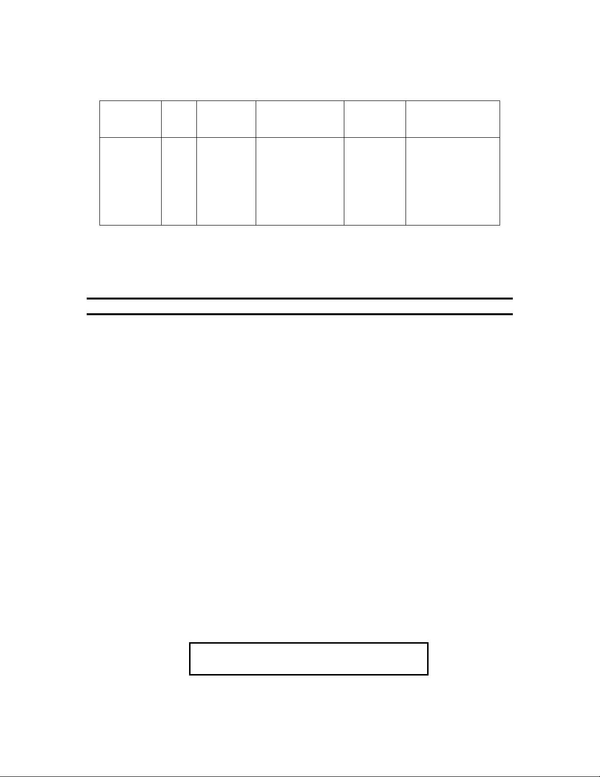
FRONTIER II JUMP STAND
INSTALLATION CHART
Refer to Fig.1
Frontier II
Stand with
FRONTIER II
IMPORTANT: The distance for setting the front bolt of the jig “S” from the waters edge is valid only if the
minimum water depth is maintained at the tip of the board noted at point A in ANSI/NSPI-5 2003, Figure 3
and Table 1. If minimum water depth is not maintained the distance “S” must be adjusted accordingly.
*WA DIMENSION IS VALID ONLY IN CONJUNCTION WITH MIN. DEPTH AT POINT A (SEE ANSI/NSPI-5 2003
FIGURE 3 AND TABLE 1) FOR POOL TYPE.
NOTE: When coping is used do not set front bolts of jig closer than 3" from the back edge of coping.
BE SURE CONCRETE DECK SURROUNDING ANCHOR JIG COMPLIES WITH MINIMUM DIMENSIONS AS SHOWN
IN FIG. 1 FOR POOL TYPE AND BOARD TO BE USED.
1. READ CAREFULLY the following, and pages A through E, which have been extracted from ANSI/NSPI-5 2003 and
pay particular attention to Figure 3 and Table 1 set forth therein.
2. The Frontier II three-bolt jig should be set in accordance with the INSTALLATION CHART above and Fig. 1, with the
"RED" capped bolt closest to the pool. This will give the desired minimum overhang. Board must be placed at deep
end of pool on centerline.
CAUTION: Before pouring concrete around jig, check the bolt pattern of jig to Fig. 2. It is possible that they have become
misaligned through shipping and handling.
3. Make sure bolts project out of concrete 1-1/2" with ample concrete depth below jig. Refer to Fig. 1 for minimum deck
thickness, width and length.
4. When finishing deck surface, maintain a LEVEL DECK SURFACE where jig bolts project out so that the stand makes
uniform contact with deck.
5. Before mounting stand, chisel away any excess concrete that may have built up around jig bolts and remove the red
and yellow bolt caps.
6. Place stand over jig bolts and secure according to Fig. 2. Tighten ANCHOR hex nuts. Tighten all MOUNTING and
ANCHOR hex nuts according to the TIGHTENING SCHEDULE in Fig. 1.
7. With Frontier II stand properly secured, select board size according to INSTALLATION CHART above. Take the
White Rubber Step Bolt Caps and pullover the heads of the 1/2" x 3" long Step Bolts. When inserting Step Bolts
through the board holes, tap with a rubber mallet in order to obtain a snug fit. Secure Frontier II jump board to stand
according to Fig. 2 and tighten MOUNTING hex nuts.
8. The top surface of the diving board shall be level from side to side.
Jump
Board
Length
ANSI/NSPI-5
2003
Pool Type
6’ I or II 26” 18” 20”
6’ III 20” 24” 26”
8’ III 34” 24” 26”
6’ IV 14” 30” 30”
8’ IV 28” 30” 30”
8’ V 22” 36” 40”
Distance For Setting
Front Bolt of Jig From
Water’s Edge
“S”
Min. Overhang
± 3”
“WA*”
Max. Height of Board
Above Water
“HOW”
INSTALLATION INSTRUCTIONS
ONLY ONE PERSON ON A JUMP BOARD AT A
TIME, WITH A MAXIMUM WEIGHT OF 250 LBS.
3

9. IMPORTANT: Refer to Table 2. Maximum diving board length, maximum height over water at point A and minimum
cross section dimensions at point A and B shall be in accordance with Table 2 and Fig 3.
Table 2- S.R. Smith Residential Pool Specifications
CROSS
SECTIONAL
DIMENSIONS
AT POINT A
CROSS SECTIONAL
DIMENSIONS AT POINT B
Pool
type
MAX. DIVING
BOARD LENGTH
MAX. HEIGHT
OVER WATER
AT POINT A
DBL** HOW** F G H J K L M N
0
I 6' DB/6’ JB 20” 2'-9" 5'-0" 4'-0" 7'-2 1/2" 7'-6" 6'-0" 3'-9" 2'-1 1/2"
II 8' DB/6’ JB 20" 2'-9" 3'-10" 4'-2" 7'-2 1/2" 7'-6" 6'-8" 3'-9" 2'-1 1/2"
III 10' DB/8’ JB 26" 2'-9" 4'-4 3/4" 4'-4 1/2" 7'-5 1/2" 8'-0" 6'-7" 3'-11 1/2" 1'-7 1/2"
IV 10' DB/8’ JB 30" 2'-9" 5'-10 1/2" 3'-10" 7'-8" 8'-6" 8'-3" 5'-7" 2'-7"
V 12' DB/8’ JB 40" 2'-9" 6'-2" 3'-11 1/2" 7'-9 1/2" 9'-0" 8'-2 1/2" 5'-9" 2'-1"
DIVING EQUIPMENT IS PROHIBITED
NOTES:
**1. ABBREVIATIONS: DBL=Diving Board Length, DB=Diving Board, JB=Jump Board, HOW=Height Over W ater.
2. IMPORTANT: The walls of a Type I Pool, when defining the Maximum Diving Water Envel ope shall be plumb.
3. All dimensions are minimum, except where noted as maximum.
4. One half (1/2) the width shown at each point shall be available on each side of the diving equipment centerline.
5. Minimum water depth under tip of diving board (Point A) is important to maintain.
FIG.3
A
WATER LEVEL
F
CROSS SECTION AT POINT A
C
L
SYM.
G
(SEE TABLE 2 FOR DIMENSIONS F-N)
H
CROSS SECTION AT POINT B
10. The top surface of the diving board from the deck end to the tip end shall be level or have an upward slope of 5/8”
per foot (16 mm: 305mm) maximum. Elevation difference shall not exceed 6 inches (152mm) from the deck end to
the tip of the board. There shall be no downward slope towards the water. The slope shall be measured using a
level as shown in Fig. 4.
MINIMUM CROSS SECTIONS
B
WATER LEVEL
C
L
SYM.
N
M
L
C
WATER LEVEL
C
J
K
CROSS SECTION AT POINT C
SYM.
L
2'-3" R. (MAX.)
D
WATER LEVEL
C
L
6" R. (MAX.)
CROSS SECTION AT POINT D
SYM.
FIG.4
11. Minimum unobstructed headroom from the top of the manufactured diving equipment shall be provided for diving in
accordance with Table 1.
TABLE 1
MINIMUM HEADROOM ABOVE
DIVING AREA
Pool Type Minimum Headroom Above
I 12 feet (3.7 m)
II 12 feet (3.7 m)
III 13 feet (4 m)
IV 13 feet (4 m)
V 14 feet (4.3 m)
Diving Surface
4

ARTICLE 5 - POOL DIMENSIONS AND TOLERANCES
EXTRACTED FROM ANSI/NSPI-5 2003
AMERICAN NATIONAL STANDARD FOR RESIDENTIAL INGROUND SWIMMING POOLS
5.1 General requirements. Design dimensions
shall comply with specifications in this standard. The
pool shall be constructed to these design dimensions
within the tolerances listed in 5.1.1.
5.1.1 Construction tolerances. There shall be
construction tolerances allowed on dimensional designs. The overall length, width and depth shall be
limited to a tolerance of plus or minus 3 inches (± 7.6
cm). All other dimensions shall be limited to a tolerance of plus or minus 2 inches (± 5.1 cm), unless
otherwise specified.
5.2 Perimeter shape. No limits ar e specified for
shape of pools except that consideration shall be
given to shape from the standpoint of circulation of
the swimming pool water and safety to the user.
5.3 Walls - requirements
5.3.1 Walls in the shallow area and deep
area of the pool shall not slope greater than 11° (1:5
slope ratio ) to a transition point. The transition point
shall not be less than 2 feet and 9 inches (83.8 cm)
below the waterline. See Fig. 1.
5.3.2 As shown in Fig. 2, at the depths of (a)
and (b), the walls are permitted to join the floor.
Figure 1- Maximum allowable wall slope
Fig. 1- Maximum allowable wall slope
Figure 2- Typical pool design configurations
A

5.3.3 The walls of Type I pool, when defining the
minimum diving water envelope, shall be plumb or
outside of Type 1 water geometry. (See figure 3, table 1.)
5.4 Maximum allowable wall slope
5.4.1 Maximum allowable wall slope shall not
slope greater than 11º from plumb.
Figure 3- Minimum water envelope
B

Table 1- Minimum water envelope
Minimum depths
Pool
type
A B C D A B C D WA AB BC CD* DE WE
at point Minimum widths at point Minimum lengths between points
O Manufactured diving equipment is prohibited
I 6'-0" 7'-6" 5'-0" 2'-9" 10'-0" 12'-0" 10'-0" 8'-0" 1'-6" 7'-0" 7'-6" Varies 6'-0" 28'-9"
II 6'-0" 7'-6" 5'-0" 2'-9" 12'-0" 15'-0" 12'-0" 8'-0" 1'-6" 7'-0" 7'-6" Varies 6'-0" 28'-9"
III 6'-10" 8'-0" 5'-0" 2'-9" 12'-0" 15'-0" 12'-0" 8'-0" 2'-0" 7'-6" 9'-0" Varies 6'-0" 31'-3"
IV 7'-8" 8'-6" 5'-0" 2'-9" 15'-0" 18'-0" 15'-0" 9'-0" 2'-6" 8'-0" 10'-6" Varies 6'-0" 33'-9"
V 8'-6" 9'-0" 5'-0" 2'-9" 15'-0" 18'-0" 15'-0" 9'-0" 3'-0" 9'-0" 12'-0" Varies 6'-0" 36'-9"
NOTE:
1. *Minimum length between points CD m ay vary based upon water depth at point D and the slope between points C & D.
2. Figure 3 drawings are not to scale.(For pool types, see Glossary.)
5.5 Offset ledges
5.6.1 The slope of the floor from the shallow end
wall towards the deep area shall not exceed 1 foot in
5.5.1 Offset ledges shall be a maximum of 8
inches (20.3 cm) wide.
5.5.1.1 Offset ledges, located less than
42 inches (1067 mm) below waterline shall be proportionately less than 8 inches (20.3 cm) wide and
fall within 11° from plumb, measured from the top of
the waterline. See figure 4.
7 feet (30 cm: 213 cm) to the point of the first slope
change as shown in figure 5.
5.6.2 Changes in slope between shallow and deep
areas shall be at a minimum water depth of 2 feet 9
inches (83.8 cm) and be at least six feet (182.9 cm)
from the shallow end, except as specified in 6.3.
5.6.3 The slope of the floor from the point of the
5.6 Floor slopes. Floor slopes shall be
reasonably uniform and comply with 5.6.1 through
first slope change toward the deep end shall not
exceed 1 foot in 3 feet (30 cm: 91 cm).
5.6.3.
Figure 4- Offset ledges
C
Figure 5- Shallow end depths

5.7 Shallow end water depths. Water depth in
the shallow area shall be a minimum of 2 feet 9
inches (83.8 cm) except for those locations specified
in 6.3 "Shallow End Detail for Beach and Sloping
Entries." The water depth at the shallowest point shall
not exceed four feet (121.9 cm) as shown in figure 5.
pools designated type I - V. Individual pool types are
shown in figure 3 and table 1.
5.9.1 Location of point A. Point A shall
be defined as a point located on the minimum water
envelopes.
5.8 Manufactured diving equipment for inground swimming pools (diving board/stand combination or manufactured platform)
NOTE – For consumer safety information, warnings and
education programs, See appendices D, E, and F.
5.8.1 When manufactured diving equipment is
installed, it shall conform to the specifications set
forth in 5.8 through 5.9 and shall be located in the
deep area of the pool so as to provide the minimum,
dimensions as shown in 5.9.
5.8.1.1 Manufactured diving equipment
shall not be installed on Type 0 pools.
5.8.2 Diving equipment. Diving equipment
shall be designed for swimming pool use and shall be
installed in accordance with the manufacturer's specifications.
5.8.2.1 Diving equipment installation
and use instructions shall be provided by the diving
equipment manufacturer and shall specify the minimum water dimensions required for each diving
board and diving stand combination. They may refer
to the water envelopes type of their choice by dimensionally relating their products to Point A on the water envelopes as shown in figure 3 and table 1, 5.9.1
through 5.9.3.
5.8.2.2 Diving equipment shall be per-
manently labeled and affixed to the diving equipment
or jump boards and shall include but not be limited
to:
- manufacturer's name and address;
5.9.1.1 Point A. Point A is a construc-
tion location nearest the deep end wall where the
minimum water depth is satisfied.
5.9.1.2 Point A as shown in figure 3
and table 1 shall be the reference point of origin for
all dimensions defining the minimum water envelope.
5.9.2 Type 0 pool (where diving is prohibited)
shall not be limited in width, length, or water depth
except as specifically provided for in this standard.
5.9.3 Location of equipment and pool fea-
tures in the minimum water envelope. If the pool is
designed for use with diving equipment, steps, pool
stairs, ladders, underwater benches, special features
and other accessory items shall be located outside the
minimum water envelope. (See figure 6)
5.9.4 Typical pool design configurations.
Vinyl liner, shotcrete, fiberglass and concrete constructions shall conform to, but are not limited to, the
typical pool configurations shown in figure 2.
5.10 Stationary diving platform(s) and diving
rock(s). Stationary diving platform(s) and diving
rock(s) built on site shall be allowed to b e flush with
the wall and located in the diving area of the pool.
Point A shall be in front of the wall at the platform or
diving rock centerline.
NOTE – For consumer safety information, warnings and
education programs, See appendices D, E, and F.
5.10.1 The maximum height of the stationary
diving platform or diving rock above the waterline
shall be as follows:
- date of manufacture;
- minimum water envelope required for
each diving board and diving stand
combination; and
- maximum weight limitations of the
user as specified by the board manufacturer.
5.8.2.3 Diving equipment shall have
slip-resisting tread surfaces.
5.9 Figure 3 contains suggested drawings and
diagrams for minimum water envelope for swimming
- Pool Type I 42 inches (106.7 cm);
- Pool Type II 42 inches (106.7 cm);
- Pool Type III 50 inches (127.0 cm);
- Pool Type IV 60 inches (152.4 cm); or
- Pool Type V 69 inches (175.3 cm)
5.10.2 Stationary diving platform(s) and div-
ing rock(s) shall not be permitted on Pool Type 0.
5.10.3 The diving equipment manufacturer
shall specify minimum headroom above water.
D

Figure 6- Top view examples of accessory equipment and pool features prohibited in the water envelope
For a copy of the complete ANSI/NSPI-5 2003 American National Standard for Residential Inground Swimming Pools
contact:
National Spa and Pool Institute
2111 Eisenhower Avenue
Alexandria, VA 22314
Phone: (703) 838-0083
Fax: (703) 549-0493
www.nspi.org
E
 Loading...