


Table of Contents Precautions ................................................................................................ 3
ENGLISH
Introduction ...............................................................................................4
Unpacking and Preliminary Inspection ........................................................4
Storage ........................................................................................................5
Safety Labels ..............................................................................................5
Location Considerations ..........................................................................5
Environment ................................................................................................5
Audible Noise ..............................................................................................5
Mounting ..................................................................................................... 5
Service Clearance .......................................................................................5
Equipment Performance .............................................................................5
Electrical ....................................................................................................5
Voltage Rating .............................................................................................5
Terminals, Wire Size, and Installation Torque ............................................ 7
Branch Circuit Overcurrent Protection ........................................................7
Location of Surge Protective Device (SPD) ................................................8
Grounding ..................................................................................................8
General .......................................................................................................9
Power System Grounding ...........................................................................9
Solidly-Grounded Power Systems ..............................................................9
Delta and Resistance-Grounded Power Systems .....................................10
Installation ...............................................................................................10
UL Conditions of Acceptability ...................................................................11
Wiring .......................................................................................................11
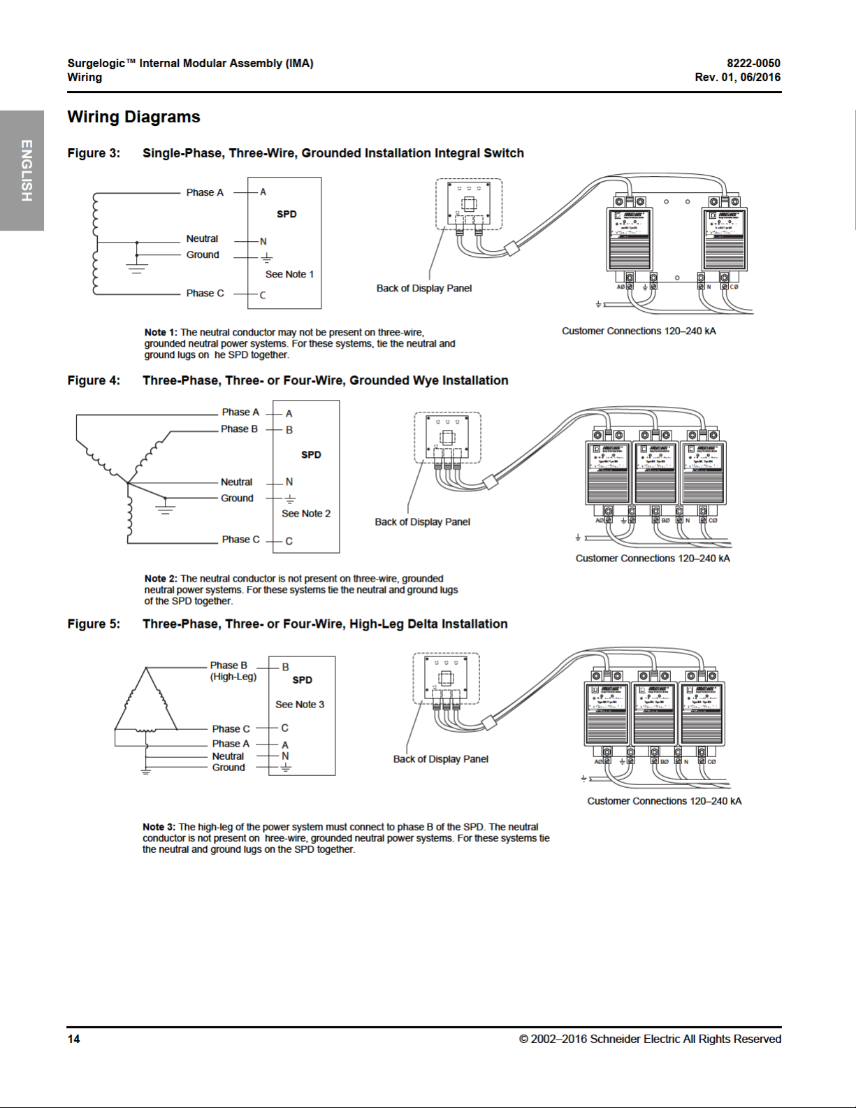
Wiring Diagrams.........................................................................................14
Wiring Diagrams for HRG and Delta Systems .......................................... 15
Operation ................................................................................................. 16
LED Status Indicators ...............................................................................16
Replacement Modules ..............................................................................17
Audible Alarm ............................................................................................18
Surge Counter ........................................................................................... 18
Dry Contacts .............................................................................................18
Remote Monitor Option .............................................................................20
Maintenance and Troubleshooting ........................................................21
Preventative Maintenance ......................................................................... 21
Troubleshooting ........................................................................................22
Replacement Parts ....................................................................................22
For troubleshooting, call the Surgelogic Technical Assistance Group at 1-800-577-7353.


Surgelogic™ Internal Modular Assembly (IMA) 8222-0050
Electrical Rev. 01, 06/2016
ENGLISH
The specifier or user of the device must be familiar with the configuration
and arrangement of the power distribution system in which any SPD is to be
installed. The system configuration of any power distribution system is
based strictly on how the secondary windings of the transformer supplying
the service entrance main or load are configured. This includes whether or
not the transformer windings are referenced to earth via a grounding
conductor. The system configuration is not based on how any specific load
or equipment is connected to a particular power distribution system. See
Table 1 for the service voltage of each SPD.
Table 1: Voltage Rating
Service Voltage
120/240 V, 1-phase,
3-wire + ground
208Y/120 V, 3-phase,
4-wire +ground Wye
240/120 V, 3-phase,
4-wire + ground High-Leg Delta
480Y/277 V, 3-phase,
4-wire + ground Wye
480 V, 3-phase,
3-wire + ground
Delta
240 V, 3-phase,
3-wire + ground
Delta
600/347 V, 3-phase,
4-wire + ground Wye
2
3
4
Peak Surge Current
Rating Per Phase
120 TVS1IMA12_
160 TVS1IMA16_
240 TVS1IMA24_
320 TVS1IMA32_
480 TVS1IMA48_
120 TVS2IMA12_
160 TVS2IMA16_
240 TVS2IMA24_
320 TVS2IMA32_
480 TVS2IMA48_
120 TVS3IMA12_
160 TVS3IMA16_
240 TVS3IMA24_
320 TVS3IMA32_
480 TVS3IMA48_
120 TVS4IMA12_
160 TVS4IMA16_
240 TVS4IMA24_
320 TVS4IMA32_
480 TVS4IMA48_
100 TVS5IMA10_
120 TVS5IMA12_
160 TVS5IMA16_
200 TVS5IMA20_
240 TVS5IMA24_
320 TVS5IMA32_
480 TVS5IMA48_
100 TVS6IMA10_
120 TVS6IMA12_
160 TVS6IMA16_
200 TVS6IMA20_
240 TVS6IMA24_
320 TVS6IMA32_
480 TVS6IMA48_
120 TVS8IMA12_
160 TVS8IMA16_
240 TVS8IMA24_
320 TVS8IMA32_
480 TVS8IMA48_
Catalog Numbers
Continued–
1
6
© 2002–2016 Schneider Electric All Rights Reserved


8222-0050 Surgelogic™ Internal Modular Assembly (IMA)
In addition to the power system configuration
and voltage, the power system grounding
method must be considered when selecting the
appropriate IMA device. Refer to the following
chart for information concerning the suitability of
IMA device to specific power system grounding
method.
CAUTION
Rev. 01, 06/2016 Grounding
General The IMA has SPD elements connected from phase to ground. It is critical
that there be a robust and effective connection to the building grounding
structure. The grounding connection must utilize an equipment grounding
conductor run with the phase and neutral connection of the power system.
Do not connect the SPD to a separate isolated ground.
For best overvoltage suppression by the IMA SPD, use a single-point
ground system where the service entrance grounding electrode system is
connected to, and bonded to, all other available electrodes, building steel,
metal water pipes, driven rods, etc. (for reference, see NEC Art 250). The
ground impedance measurement of the electrical system should be as low
as possible and in compliance with all applicable codes.
ENGLISH
Power System Grounding
Solidly-Grounded Power Systems
Table 3: Grounding Methods
IMA Device Catalog Number Power System Grounding Method
TVS1IMA__
TVS2IMA__
TVS3IMA__
TVS4IMA__
TVS8IMA__
TVS5IMA__
TVS9IMA__
SURGE PROTECTIVE DEVICE DAMAGE AND POWER SYSTEM OVERVOLTAGE
Solidly-Grounded
Ungrounded / HRGTVS6IMA__
• Do not connect devices rated for use on solidly-grounded power systems
to resistance-grounded (for example, High Resistance Ground) or
ungrounded power systems.
• Verify that the service entrance equipment is bonded to ground in
accordance with all applicable codes.
• Verify that the neutral terminal of the power system transformer feeding
the device is bonded to system ground in accordance with all applicable
.
codes
© 2002–2016 Schneider Electric All Rights Reserved
Failure to follow these instructions can result in equipment damage.
SPDs rated for use on solidly-grounded power systems must not be connected
to resistance-grounded or ungrounded power systems. Such a connection can
result in damage to the SPD.
Always verify the power system grounding configuration prior to application
of power to the device. Confirm that all ground bonds are installed at both
the service entrance equipment and power system transformer prior to
application of power.
9


Surgelogic™ Internal Modular Assembly (IMA) 8222-0050
Wiring Rev. 01, 06/2016
ENGLISH
Follow the steps listed below when making wiring connections:
1. Turn off all power supplying this equipment before working on or inside
any enclosure containing this equipment.
2. Confirm the SPD voltage rating and configuration is the same as the
system voltage and power system configuration to which it will be
connected.
3. Identify proper location for surge protective device. Locate as close as
possible to the panel being addressed so the wires are as short as
possible. Mount unit securely.
Note: The surge protective device must be installed in an accessible
location as described in the NEC.
4. Install in accordance with national and local electrical codes for
overcurrent protection recommendations and wire ampacity
considerations.
Note: The neutral connection is not present on three-wire, three-phase
wye ground or two-wire single-phase mid-point ground power systems.
For these systems, bond the neutral and ground lugs together in the
SPD. For a High Resistance Ground (HRG) or Delta SPD, no neutral
connection exists. For installation wiring see Figures 6 and 7.
Note: See Terminals, Wire Size, and Installation Torque and Table 2 on
page 7 for acceptable wire size and installation torque.
5. Twist conductors ½ turn or more for every twelve inches of length. Do
not loop or coil wires. Be sure to maintain adequate wire bending space
per NEC.
6. If the remote signaling contacts of the diagnostic display panel are to be
used, refer to the section, “Dry Contacts”, on page 18 for wiring
instructions.
7. On a High-Leg Delta installation, note the high leg connection per wiring
diagram. See Figure 5.
8. Replace all devices, doors and covers before turning on power to the
equipment. If the SPD is properly installed and functioning, the green
LED indicators on the display will be lit.
For questions pertaining to the installation of this device, contact the
Surgelogic Technical Assistance Group at 1-800-577-7353.
12
© 2002–2016 Schneider Electric All Rights Reserved


8222-0050 Surgelogic™ Internal Modular Assembly (IMA)
Left green LED lit:
L-G suppression
is operating.
Left green LED not lit:
Loss of surge suppression
from L-G.
Right green LED not lit:
Loss of surge suppression from
L-N for MA(1, 3, 4, or 8)IMA_
L-L for
Right green LED lit:
Suppression is operating
L-N for MA(1, 3, 4, or 8)IMA_
L-L for
MA(5, 6, or 9)IMA_ (Delta/HRG)
MA_IMA_LL (L-L Enhanced)
MA(5, 6, or 9)IMA_ (Delta/HRG)
MA_IMA_LL (L-L Enhanced)
Rev. 01, 06/2016 Operation
Figure 8: MA Module LEDs
ENGLISH
Replacement Modules
Table 4: IMA Replacement Modules
System Voltage
120/240 V, 1-phase,
3-wire + ground
208Y/120 V, 3-phase,
4-wire + ground
120/240 V, 3-phase,
4-wire + ground
High-Leg Delta
240 V, 3-phase,
3-wire + ground
480Y/277 V, 3-phase,
4-wire + ground Wye
480 V, 3-phase,
3-wire + ground
600Y/347 V, 3-phase,
4-wire + ground
600 V, 3-phase,
3-wire + ground
1
Catalog numbers are representational. Actual catalog numbers require a suffix to indicate UL
Type.
2
208Y/120 series also applies to the following voltage 220Y/127.
3
High-Leg Delta (Phase B modules are different than Phase A and Phase C modules).
4
480Y/277 series applies to the following voltages 380Y/220, 400Y/230 and 415Y/240.
5
480 V Delta series also applies to the following voltages: 480Y/277V HRG.
6
600 V Delta series also applies to the following voltages: 600Y/347V HRG.
Wye
Delta
Delta
Wye
Delta
2
3
5
6
Peak Surge
Current Rating (kA)
120
160
240
120
160
240
120
160
240
120
160
240
4
120
160
240
120
160
240
120
160
240
120
160
180
MA1IMA12_
MA1IMA16_
MA1IMA24_
MA1IMA12_
MA1IMA16_
MA1IMA24_
MA1IMA12_
MA1IMA16_
MA1IMA24_
MA6IMA12_
MA6IMA16_
MA6IMA24_
MA4IMA12_
MA4IMA16_
MA4IMA24_
MA5IMA12_
MA5IMA16_
MA5IMA24_
MA8IMA12_
MA8IMA16_
MA8IMA24_
MA9IMA12_
MA9IMA16_
MA9IMA18_
Catalog Numbers
Phase A Phase B Phase C
—
—
—
MA1IMA12_
MA1IMA16_
MA1IMA24_
MA3IMA12_
MA3IMA16_
MA3IMA24_
MA6IMA12_
MA6IMA16_
MA6IMA24_
MA4IMA12_
MA4IMA16_
MA4IMA24_
MA5IMA12_
MA5IMA16_
MA5IMA24_
MA8IMA12_
MA8IMA16_
MA8IMA24_
MA9IMA12_
MA9IMA16_
MA9IMA18_
1
MA1IMA12_
MA1IMA16_
MA1IMA24_
MA1IMA12_
MA1IMA16_
MA1IMA24_
MA1IMA12_
MA1IMA16_
MA1IMA24_
MA6IMA12_
MA6IMA16_
MA6IMA24_
MA4IMA12_
MA4IMA16_
MA4IMA24_
MA5IMA12_
MA5IMA16_
MA5IMA24_
MA8IMA12_
MA8IMA16_
MA8IMA24_
MA9IMA12_
MA9IMA16_
MA9IMA18_
© 2002–2016 Schneider Electric All Rights Reserved
17


 Loading...