

Page 1
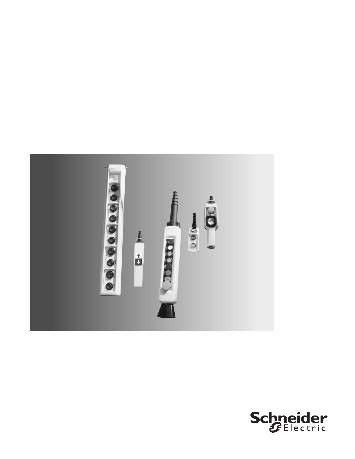
Pendant Stations
Type BW, XACA, and SKYP
Catalog
9001CT1001R07/13
2013
Class 9001
™
Page 2

Pendant Stations
™
CONTENTS
Description . . . . . . . . . . . . . . . . . . . . . . . . . . . . . . . . . . . . . . . . . . . . . Page
Type BW
General Information . . . . . . . . . . . . . . . . . . . . . . . . . . . . . . . . . . . . . . . . .3
Specifications and Dimensions. . . . . . . . . . . . . . . . . . . . . . . . . . . . . . . . .3
Type XACA
General Information and Specifications . . . . . . . . . . . . . . . . . . . . . . . . . .7
Worksheet. . . . . . . . . . . . . . . . . . . . . . . . . . . . . . . . . . . . . . . . . . . . . . . .12
Dimensions. . . . . . . . . . . . . . . . . . . . . . . . . . . . . . . . . . . . . . . . . . . . . . .13
Type SKYP
General Information and Specifications . . . . . . . . . . . . . . . . . . . . . . . . . 14
Worksheet. . . . . . . . . . . . . . . . . . . . . . . . . . . . . . . . . . . . . . . . . . . . . . . .18
Dimensions. . . . . . . . . . . . . . . . . . . . . . . . . . . . . . . . . . . . . . . . . . . . . . .19
Index . . . . . . . . . . . . . . . . . . . . . . . . . . . . . . . . . . . . . . . . . . . . . . . . . . . . .20
2
07/2013 © 2013 Schneider Electric
All Rights Reserved
Page 3
Pendant Stations
BW90/BW100
OFF and STOP
are white letters
on a red background
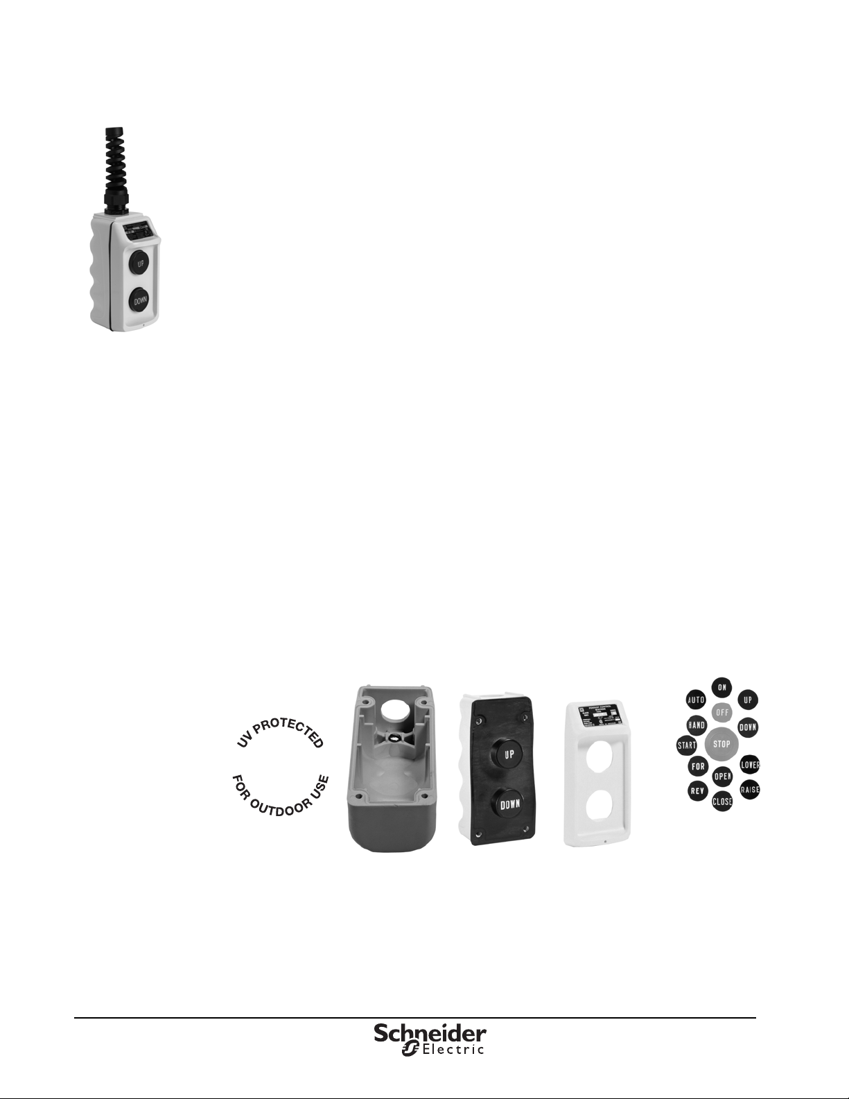
Type BW Standard Duty Pendant Stations
Type BW Standard Duty Pendant Stations
All of the features of the Class 9001 Type BW pendant stations with external strain relief are now
pre-assembled into one catalog number.
• Push button legend inserts
• Field-installable mushroom button
• Full cover gasket, to exclude harmful contaminants
• Jumper, included on all single speed buttons (except universal types), to save wiring time
• Self-lifting pressure wire connectors, for easy wiring
• Operator and contact sold as one unit
The Class 9001 Type BW Pendant Station is a pre-assembled, 2-button station well suited for standard
hoist applications. Oversized finger grips on the rear of the encl osu re make it easy to grip and ope rate.
Features and Options
• Made of high impact thermoplastic with UL 94V rating (self-extinguishing flammability)
• NEMA 1, 3, 3R, 4, and 4X watertight, dusttight, oiReplaces 9001CT1001, 12/2010ltight, and
corrosion resistant
• UL Listed and CSA approved
• 1/2" conduit opening
• Internal strain-relief post
• Momentary or maintained contact
• Single speed or two speed
• With or without a mechanical interlock
• Optional external hanger bracket and seal
• Ribs on the top of the enclosure to prevent the hanger bracket from rotating and coming loose
• Contoured for easy grip
• Easy to hold with one hand
© 2013 Schneider Electric
All Rights Reserved
™
07/2013
3
Page 4
Pendant Stations
™
®
Marking
Specifications
Specifications
The Class 9001 BW90 and BW100 pendant stations are used for hoist applications requiring either
single-speed or two-speed buttons. These thermoplastic enclosures have a 1/2-inch conduit entrance
at the top to accept a pendant cable. Internal and external strain relief comes standard. The stations
are rated NEMA Type 1, 3, 3R, 4, and 4X. The enclosure is available in three colors. All universal
stations have double circuit blocks (1 N.O.—1 N.C.) on each button and come without legends so they
can be assembled to fit the application. For convenience, push buttons have interchangeable legend
inserts. The complete line is UL listed and CSA certified.
Table 1: General Specifications, Type BW
Electrical Ratings
Enclosure Type
Operating Temperature
Storage Temperature
Housing Material
AC = NEMA / UL B600; DC = NEMA / UL P600
NEMA / UL Type 1, 3, 3R, 4, and 4X
–25 C to +60 C (–13 F to +140 F)
–40 C to +70 C (–40 F to +158 F)
Polycarbonate/PET Polyester Blend
Approvals
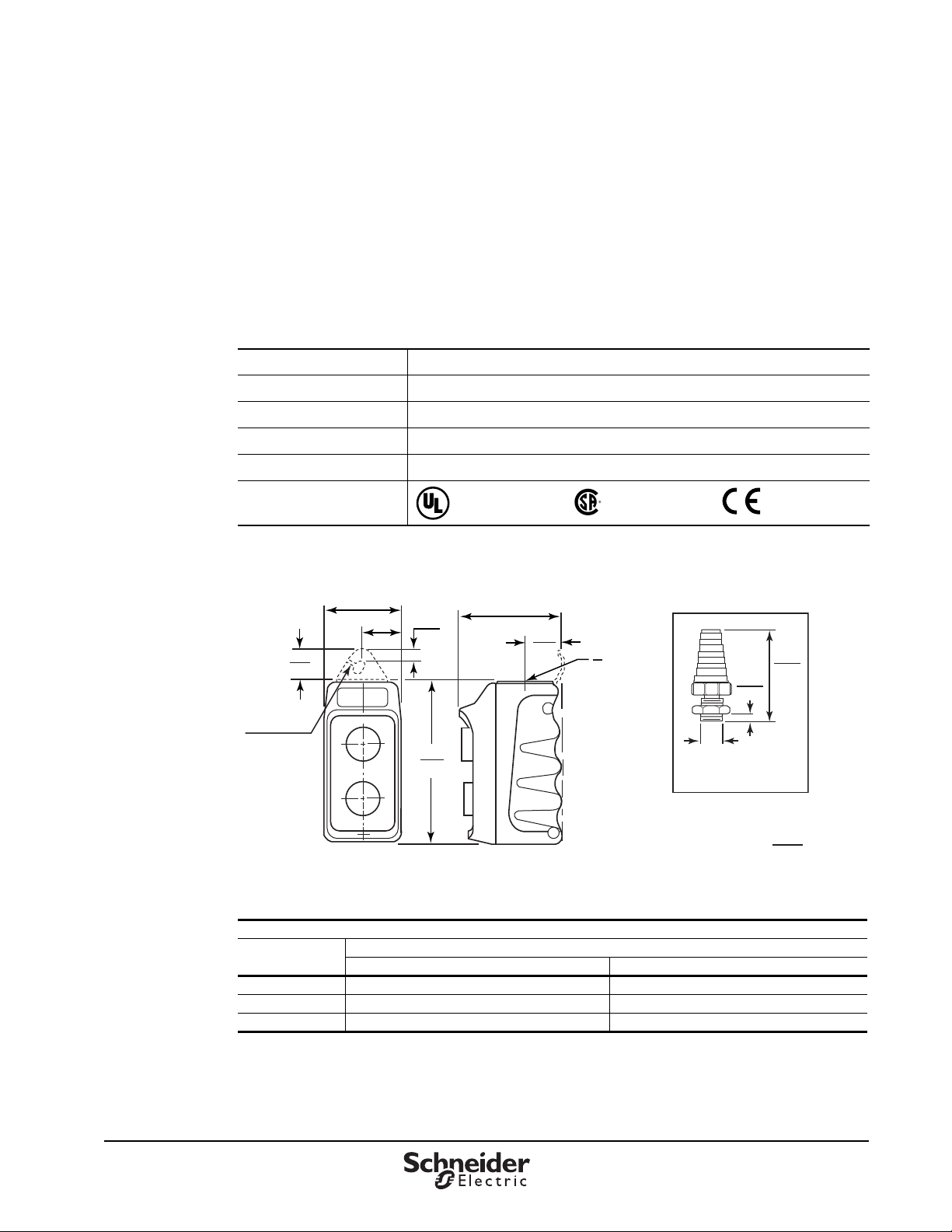
Figure 1: Dimensions, Type BW
2.19
0.91
23
0.25 0.50
Mounting Slot
56
1.09
0.43
28
11
4.69
119
File E78403
CCN NKCR
2.94
75
1.06
27
File LR 25490
Class 3211 03
1
- 14
2
NPT
4.135
105
0.591
15
1/2" NPT
Strain Relief Connector
Dual Dimensions
inches
mm
Table 2: Electrical Ratings DC
DC—NEMA / UL P600
Volts
120 1.10 5
240 0.55 5
600 0.20 5
Make and Break Amperes Continuous Carrying Amperes
4
07/2013 © 2013 Schneider Electric
Inductive and Resistive
All Rights Reserved
Page 5
Pendant Stations
BW90 / BW100
Specifications
Table 3: Electrical Contact Ratings, AC, Type BW
AC—NEMA / UL B600
Inductive,
[1]
Volts
120 30.0 3600 3.0 360 5 5
240 15.0 3600 1.5 360 5 5
480 7.5 3600 0.75 360 5 5
600 0.6 3600 0.6 360 5 5
1
OSHA Regulation, Section 1910.170 Overhead and Gantry Cranes, limits the voltage at pendant push buttons to 150 Vac or 300 Vdc.
Make Break
AVAAVA
35% Power Factor
Continuous
Carrying Amperes
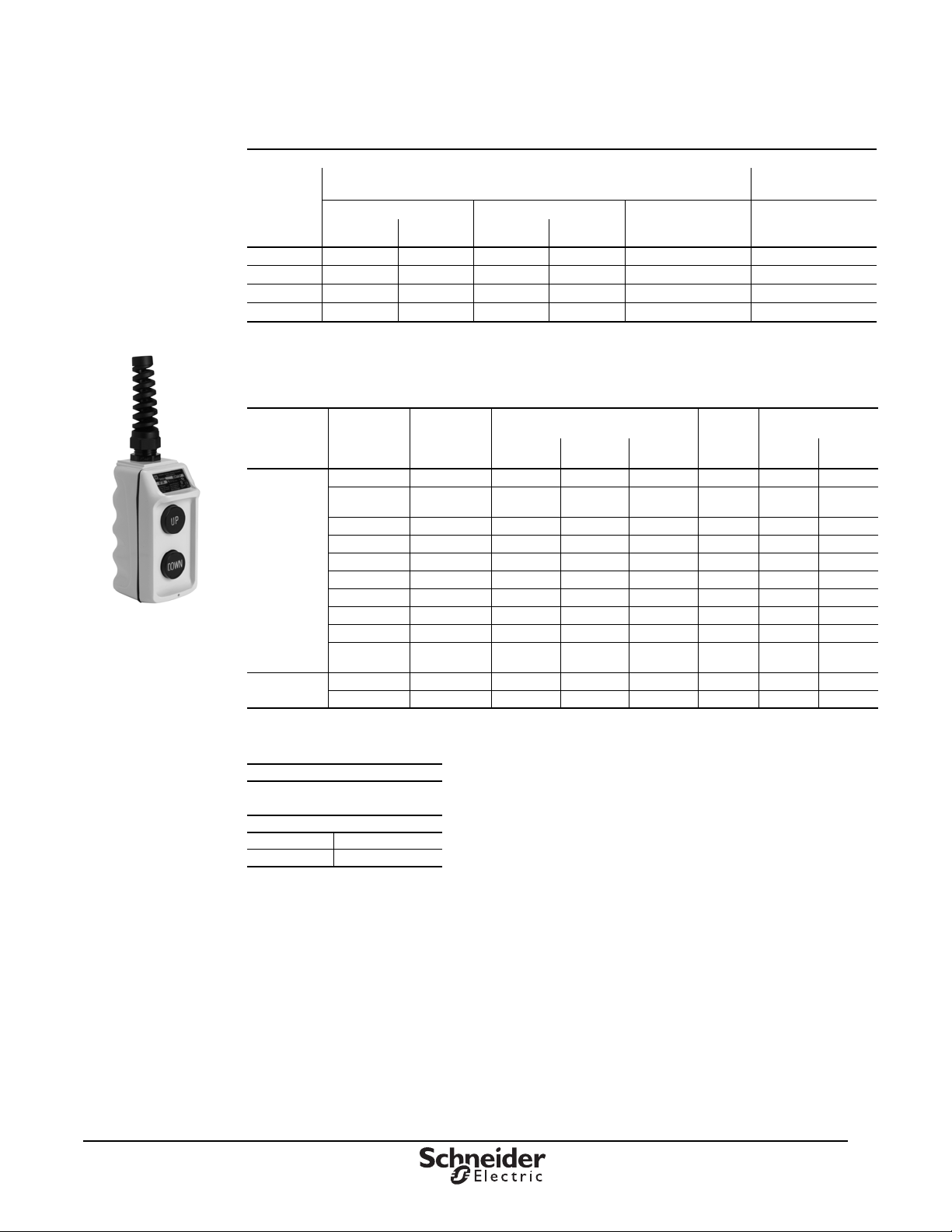
Table 4: Type BW90 and BW100 Pendant Stations with Cord Connector and Strain Relief
Description
Single
Speed
Two
Speed
1
Maintained contact
Legend Insert
Markings
Up-Down Yes BW92Y BW92B BW92R 146 BOC368 146
Forward-
Reverse
On-Off
Start-Stop No BW95Y BW95B BW95R 145 BOC359 25
Start-Stop
On-Off
Up-Down Yes BW98Y BW98B — 100 — —
Without Inserts Yes BW90YU BW90BU BW90RU 147 BOC366 25
Without Inserts No BW91Y U BW91BU BW91RU 25 BOC359 25
Without
Inserts
Without Inserts Yes BW100YU BW100BU BW100RU 150 BOC367 150
Up-Down Yes BW102Y BW100B BW102R 150 BOC367 150
Mechanical
Interlock
Yes BW93Y BW93B BW93R 146 BOC368 146
[1]
Yes BW94Y BW94B BW94R 10 BOC358 147
[1]
Yes BW96Y BW96B BW96R 10 BOC358 147
[1]
No BW97Y BW97B BW97R 146 BOC359 25
Yes BW94YU BW94BU BW94RU 147 BOC358 147
[1]
Yellow Black Red
Enclosure Color
Contact
Symbol
Resistive,
75% Power Factor
Make, Break,
and Continuous
Carrying Amperes
Replacement
Interior
9001
Type
Contact
Symbol
© 2013 Schneider Electric
All Rights Reserved
Table 5: How to Order
Specify:
• Class Number
• Type Number
Catalog Number:
Class Type
9001 BW92Y
5
07/2013
™
Page 6
Pendant Stations
™
10
25
100
147
146
145
150
Speed 1
Speed 2
Speed 1
Speed 2
Each button has
1 N.O. contact
with 4 terminals.
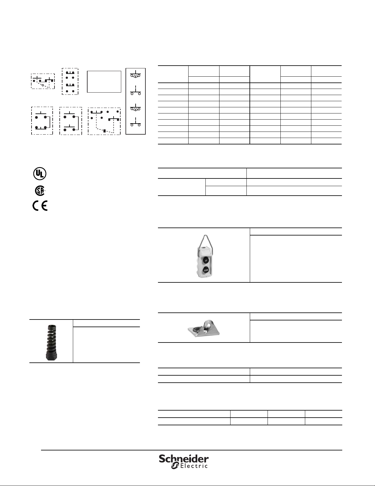
Figure 2: Contact Symbols
Approvals
File E78403
CCN NKCR
File LR 25490
Class 3211 03
®
Marking
Specifications
Table 6: Interchangeable Push Button Le ge n d Ins e rt s for
Push
Button
[1]
Mushroom
Button
9001 BW Pendants, NEMA / UL Type 4X
Push
Marking
Start B259 B282 On B257 B280
Stop B260 B283 Off B258 B281
Forward B255 B278 Hand B265 B288
Reverse B256 B279 Auto B266 B289
Open B263 B286 — — —
Close B264 B287 Black B251 B251
Raise B261 B284 — — —
Lower B262 B285 Red B252 B252
Up B253 B276 — — —
Down B254 B277 — — —
1
Order in multiples of 10.
Button
Type Type Type Type
Mushroom
Button
Marking
Table 7: Legend Insert Kit
Where Used: Type
For NEMA Type 4X:
Type BW70, BW80,
BW90, and BW100
1
Kit includes one each of standard legend inserts as indicated under Type of kit.
Table 8: Hanger Bracket
Push Button B250 (includes 1 each of B253 through B266)
Mushroom Button B300 (includes 1 each of B276 through B289)
[1]
[1]
(Factory Installed Only on Type BW7 and BW8 )
Form
Y236
1
Addition of the external hanger bracket (similar to the one used on Class 9001 Type SKYP
pendant stations). Use when polymeric cord connectors are required.
Table 9: Strain Relief Replacement for
Type BW9
and BW10
Order Number
BWSR
Table 10: Hanger Bracket and Seal Kit
Order Number
B350
Table 11: Mushroom Button (without Button Insert) for
9001 BW Pendants, NEMA / UL Type 4X
Color Type
Red B303
1
See page 3 for dimensions.
Table 12: 9001 BW Pendant Replacement Enclosures
Description Yellow Red Black
6
07/2013 © 2013 Schneider Electric
Box and cover with four screws BWRY BWRR BWRB
1
Screws are required. Order quantity of four, catalog no. 3110128001.
[1]
[1]
All Rights Reserved
Page 7
Pendant Stations
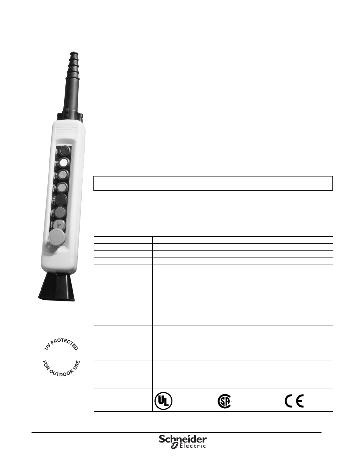
XACA08
Shown with optional
operators and accessories.
®
File E164353
CCN NKCR
File LR 44087
Class 3211 03
Marking
Type XACA General Information
Type XACA General Information
XACA pendant stations are designed for standard- or medium-duty control circuit applications. The
enclosures are made from rugged, double insulated thermoplastic material. These stations have been
designed for easy handling and operation, even with heavy work gloves.
Two styles of stations are offered: “small hoist” pistol grip stations with integral parts (see Table 14 on
page 8), and “general purpose” station components with mo dular assembly required. The general
purpose components are available as custom, factory-assembled stations. For custom applications, a
wide range of operators, contact blocks, legend plates, and accessories are offered.
Features Applications
• Single- and two-speed versions • Overhead cranes
• Double insulated • Tower cranes
• Shock and corrosion resistant • Fixed hoists
• 2, 4, 6, 8, 12 element versions • Beam hoists
• Ease of operation
To place a custom pendant order, use the worksheet on 12 as a guide. Orders must be placed
through the Product Selector in Quote to Cash. There is a 10% charge for assembly.
Type XACA Specifications
Table 13: XACA Specifications
Electrical Ratings NEMA / UL A600, Q600
Enclosure XACA0 NEMA / UL Type 4, 4X (Indoor/Outdoor), 5, IP 65
XACA2 (Pistol Grip) NEMA / UL Type 4, 4X (Indoor/Outdoor), 5, IP 65
Operating Temperature -15 °C to +70 °C (-5 °F to +158 °F)
Storage Temperature -40 °C to +70 °C (-40 °F to +158 °F)
Housing Material Yellow polypropylene V2
Shock Resistance 100 g
Vibration Resistance 15 g for 40 to 500 Hz
1 million operations
(The product life expressed is based on average usage and normal operating conditions. Actual
Mechanical Life
Operating Force
Cable Entry
Cabling
Approvals
operating life varies with conditions. The above statements are not intended to nor shall they
create any express or implied warranties as to product operation or life. For information on the
limited warranty offered on this product, please refer to Sc hneid er Electri c t erms a nd cond iti ons of
sale found in the Digest.)
XACA multi-element types
• With contact ZB2BE: 1 daN (36 oz.) for 1 N.O.; 1.3 daN (46.8 oz.) for 1 N.O. / 1 N.C.
• With contact XENG1491: 1.4 daN (50.4 oz.) for 1 N.C. / 2 N.O.
• With contact XENG1191: 1.4 daN (50.4 oz.) for 1st step; 2.5 daN (89.9 oz.) for 2nd step
XACD: 7 to 18 mm
All other models: 9 to 13 mm
Screw and captive cable clamp terminals. Recommended torque 15.62 lb-in (0.8 N•m nominal,
1.2 N•m maximum)
Capacity: minimum 1 x 0.5 mm
2 x 1.5 mm
NF C 20- 20 (on request).
2
(16 AWG) or 1 x 2.5 mm2 (14 AWG) or by cable quick connector conforming to
2
(20 AWG) solid or stranded; maximum, with or without cable end:
© 2013 Schneider Electric
All Rights Reserved
07/2013
7
™
Page 8
Pendant Stations
™
XACA03
(Shown with
optional operator)
XACA06
XACA2013
13 14
21 22
33
34
13
14
21
22
33
34
13 14 13 14
13 14
11 12
1112
2122
3132
AB CDE
XACS10•
XENG1191
XENG37•1
ZB2BE10•
Type XACA Specifications
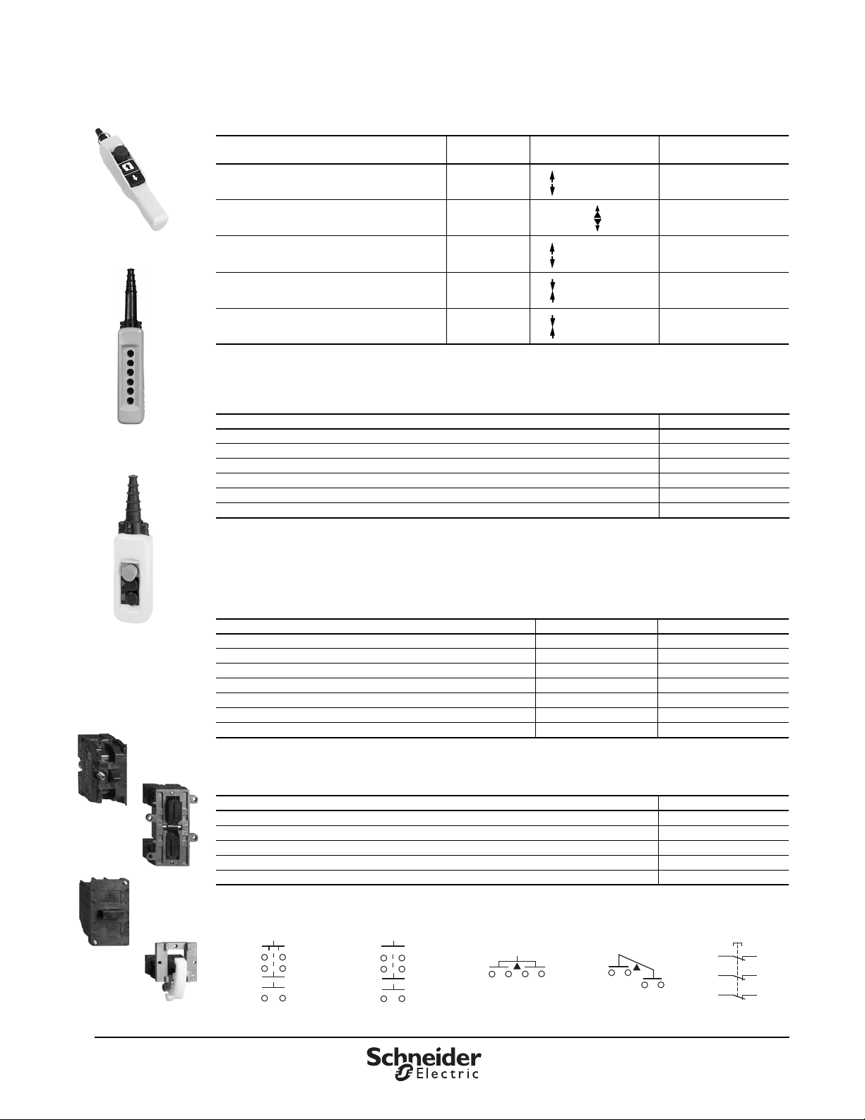
Table 14: Pistol Grip Stations
Description Speeds
1 N.O. contact per operator
2 mechanically interlocked operators
Function
1 Speed / 2 Speed
1 XACA201
Catalog Number
[1]
2 N.O. (staggered) contacts per operator
2 mechanically interlocked operators
1 N.O. + 1 N.C.
2 mechanically interlocked operators
1 N.O. contact per direction
1 mechanically interlocked 2 way toggle
1 N.O. & 1 N.C. contact per direction
1 mechanically interlocked 2 way toggle
1
These XAC units are available with factory installed E-stops. Add a 3 to the end of the catalog number fo r the standard E-stop or
add a 4 for a trigger action E-stop. E-stops include one N.C. contact block.
Table 15: General Purpose Pend ants
Enclosures Catalog Number
2-hole enclosure XACA02H7
3-hole enclosure (top hole is for E-stop only) XACA03H7
4-hole enclosure XACA04H7
6-hole enclosure XACA06H7
8-hole enclosure XACA08H7
12-hole enclosure XACA12H7
1
Standard enclosures include internal mou nting plate, cable sleeve f or 8 to 26 mm, internal cable clamp, suspension ring and cable tie.
2
Due to space limitations, two ZB2BE101 or ZB2BE102 contact blocks will fit behind each operator, but only one of any other
contact block. Potentiometers will not fit in the enclosures.
3
Cannot use base-mounted items or mounting adapter.
Table 16: Contact Blocks for Operators in Cover
Description Wiring Diagram Catalog Number
1 N.O. / spring return / 1 speed — ZB2BE101
1 N.C. / spring return / 1 speed — ZB2BE102
1 N.O. early close, and 1 N.C. and 1 N.O. / spring return / 2 speed A XENG1191
1 N.C. and 2 N.O. / spring return / 1 speed B XENG1491
1 N.O. and 1 N.O. latching / 1 speed / interlocked C XENG3781
1 N.O. and 1 N.C. latching / 1 speed / interlocked D XENG3791
N.C. + N.C. + N.C. with positive opening operation E XENT1192
1
For mounting in enclosures: XACA03 (frontal cut-out); XACA05, A06, A08 (frontal or base cut-out).
2 XACA207
1 XACA205
1 XACD21A0101
1 XACD21A0105
[1, 2]
[1]
[1]
[1]
[3]
Table 17: Contact Blocks For Operators in Base of Enclosure
Description Catalog Number
1 N.O. / 1 speed XACS101
1 N.C. / 1 speed XACS102
2 N.O. / 1 speed XACS103
2 N.C. / 1 speed XACS104
1 N.O. and 1 N.C. / 1 speed XACS105
1
Cannot be used with XACA03 pendant.
8
[1]
07/2013 © 2013 Schneider Electric
All Rights Reserved
Page 9
Pendant Stations
Booted Push Button
Selector Switch
(Key Operated)
Selector Switch
Mushroom Head
Wobble stick
XACB961 XACA971
XACA982
XACA983
Type XACA Specifications
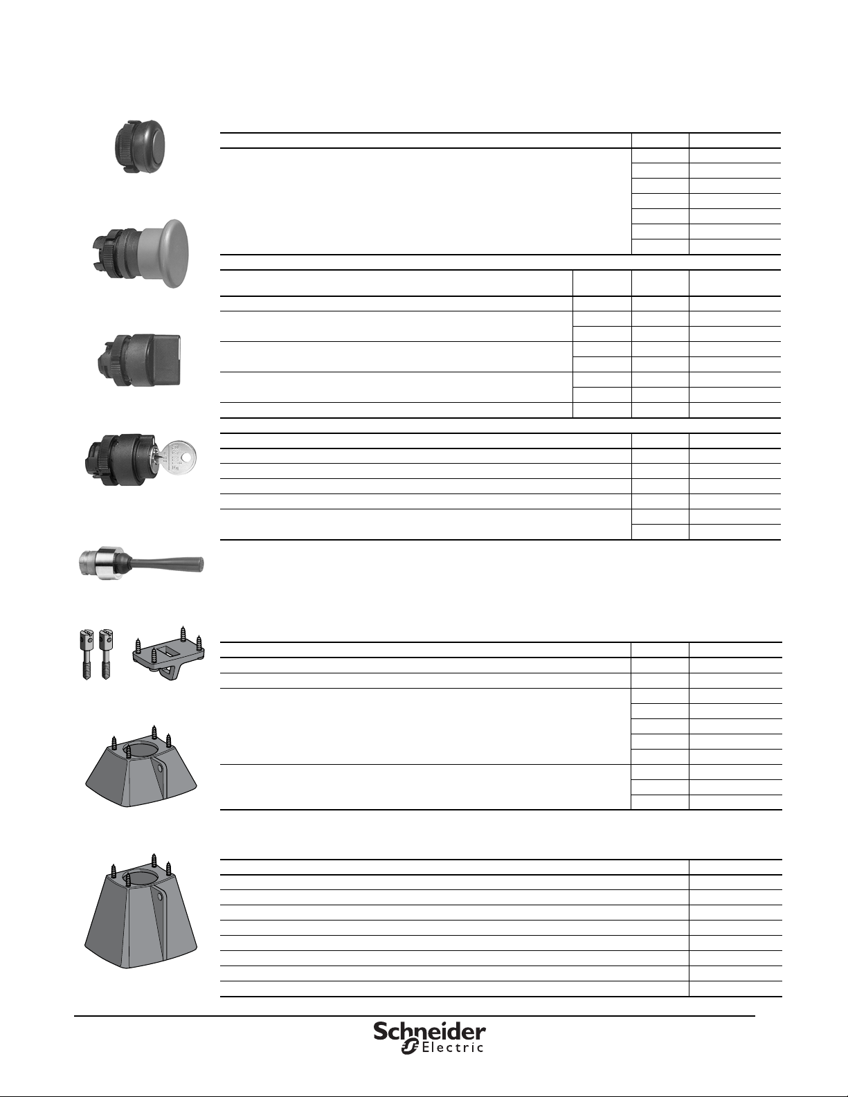
Table 18: Operators
Description Color Catalog Number
Booted push button
Description
Mushroom head, momentary 30 mm Red ZA2BC44
Mushroom head, push to maintain / turn to release
Mushroom head, push to maintain / turn to release (trigger action)
Mushroom head, push to maintain / key turn to release
Mushroom head, push to maintain / key turn to release (trigger action)
Description Color Catalog Number
Selector switch / 2 position—maintained
Selector switch / 3 position—maintained
Selector switch / 2 position—maintained key operated—key removal from left or right position
Selector switch / 3 position—maintained key operated—key removal from left or right position
Wobble stick (bottom mounting recommended)
1
Booted push buttons are for cover mounting only. All other operators can be mounted on cover or bottom.
2
Trigger action mushroom heads are tamper-proof, meaning t hat teasing or floating the opera tor does not change the contact state.
3
Not for use with XENG or XENT contact blocks.
[1]
White XACA9411
Black XACA9412
Green XACA9413
Red XACA9414
Yellow XACA9415
Blue XACA9416
Brown XACA9419
Mushroom
Size
30 mm Red ZA2BS44
40 mm Red ZA2BS54
[2]
[2]
[3]
[3]
30 mm Red ZA2BS834
40 mm Red ZA2BS844
30 mm Red ZA2BS74
40 mm Red ZA2BS14
40 mm Red ZA2BS844
Color Catalog Number
Black ZA2BD2
Black ZA2BD3
[3]
NA ZA2BG4
[3]
NA ZA2BG5
Black ZA2BB2
Red ZA2BB4
Table 19: Pilot Light Components
Description Color Catalog Number
Direct supply base without lamp (for 6–120 V applications) (AC/DC) — ZB2BV006
Resistor supply base with 130 V lamp (for 220–240 V applications) (AC/DC) — ZB2BV007
Green ZA2BV03
Red ZA2BV04
Pilot light operators for incandescent lamps
Pilot light operators for LED lamps
Amber ZA2BV05
Blue ZA2BV06
Clear ZA2BV07
Green ZA2BV033
Red ZA2BV043
Amber ZA2BV053
© 2013 Schneider Electric
All Rights Reserved
Table 20: Enclosure Accessories
Description Catalog Number
Blank hole plug ZB2SZ3
Mechanical interlock (momentary). For use with XAC booted operators only. XACA009
Screw adapter for self-supporting cable XACB961
Low suspension ring for single row station XACA971
Protective guard for bottom mounted mushroom head XACA982
Protective guard for bottom mounted selector switch or key switch XACA983
Cable sleeve (XACA20
Cable sleeve (XACA••) XACA960
•)—pistol grip style XACA913
07/2013
™
9
Page 10
Pendant Stations
™
Type XACA Specifications
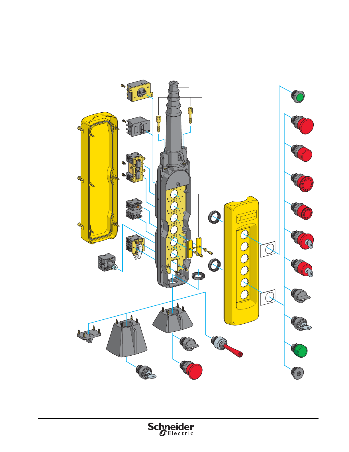
Figure 3: Exploded View
XENT1192
XACA960
XACB961
XACA941●
ZB2BV00
●
XENG1● 91
●1
XENG37
ZB2BE●●●
XACS
●●●
XACA009
ZA2BC4
ZA2BC44
ZA2BS54
ZA2BS44
ZA2BS14
ZB2BY●●●●
ZA2BS74
ZA2BD●
ZA2BG●
ZA2BV0●
ZB2SZ3
XACA971
XACA983
ZA2BG●
XACA982
●
ZA2BD
ZA2BC●●BS●●
ZA2BB ●
ZB2BY
●●●●
10
07/2013 © 2013 Schneider Electric
All Rights Reserved
Page 11
Pendant Stations
DL1CE0••
(Incandescent)
DL1CJUS••••
(LED)
Type XACA Specifications
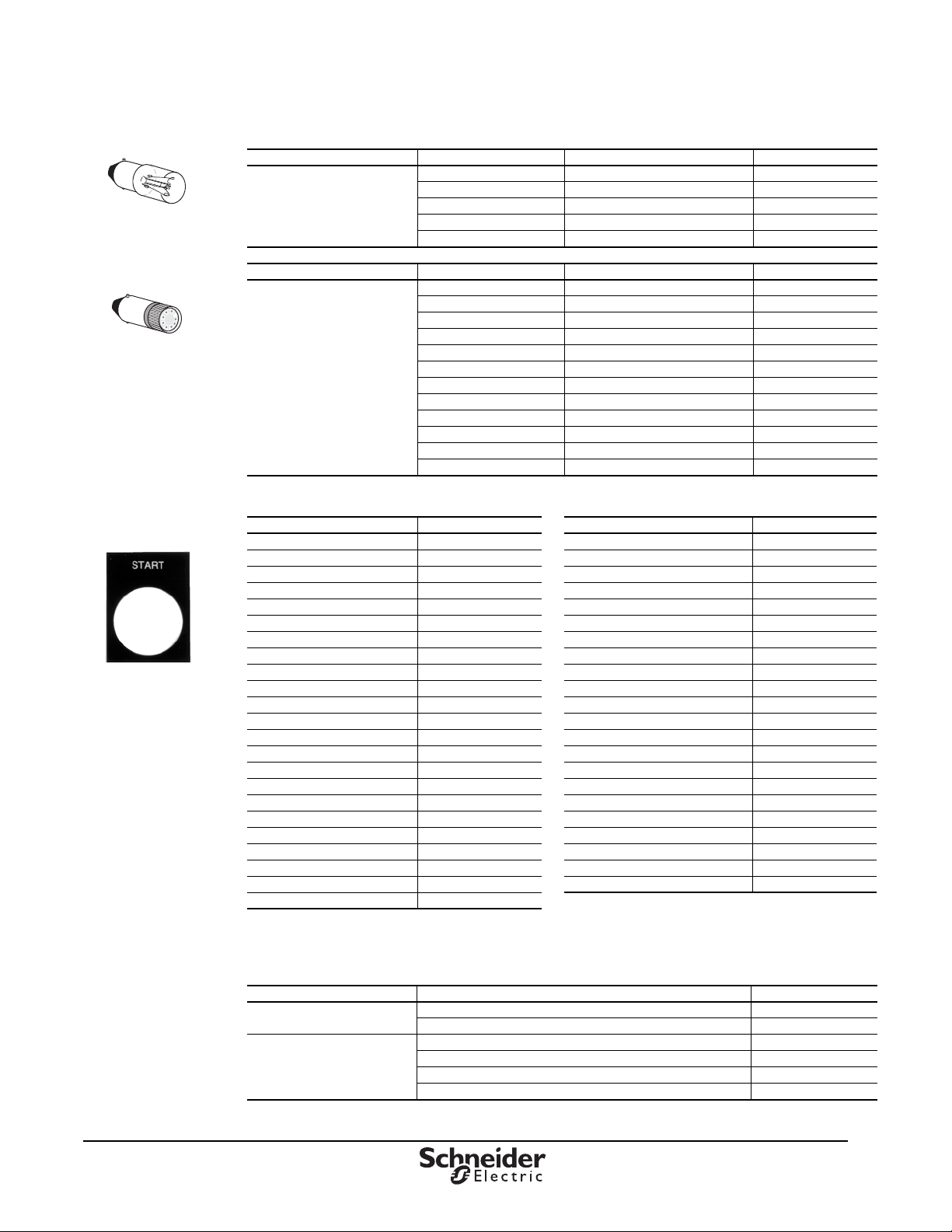
Table 21: Lamps
Type Voltage (AC/DC) Watts Catalog Number
61.2 DL1CB006
Replacement Bulbs
Type BA9s
Incandescent
Type Color Voltage Catalog Number
LED, BA9s Base for
Direct Supply Blocks
Table 22: PVC Standard Legend Plates 30 x 40 mm
[1]
Text
Bridge Forward ZB2BY2343 Off ZB2BY2312
Bridge Reverse ZB2BY2344 On ZB2BY2311
Close ZB2BY2314 Off On ZB2BY2367
Down ZB2BY2308 Open ZB2BY2313
Emergency Stop ZB2BY2330 Open Close ZB2BY2376
Fast ZB2BY2328 Open-O-Close ZB2BY2388
Forward ZB2BY2305 Out ZB2BY2339
For Rev ZB2BY23 Power On ZB2BY2326
For-O-Rev ZB2BY2384 Raise ZB2BY2335
Hand Off Auto ZB2BY2387 Reset ZB2BY2323
High ZB2BY2338 Reverse ZB2BY2306
High Low ZB2BY2369 Right ZB2BY2309
Hoist Down ZB2BY2342 Run ZB2BY2334
Hoist Up ZB2BY2341 Slow ZB2BY2327
In ZB2BY2503 Start ZB2BY2303
Inch ZB2BY2321 Stop ZB2BY2304
Jog For ZB2BY2381 Stop Start ZB2BY2366
Jog Rev ZB2BY2380 Trolley Right ZB2BY2345
Jog Run ZB2BY2365 Trolley Left ZB2BY2346
Left ZB2BY2310 Up ZB2BY2307
Low ZB2BY2336 Up Down ZB2BY2370
Lower ZB2BY2337 Up-O-Down ZB2BY2389
Man Auto ZB2BY2372
1
All nameplates are black with white lettering except “Stop”, “Emergency Stop”, and “Reset,” which are red with white lettering.
For black “Reset,” change the final digit of the catalog number to 2.
12 2.0 DL1CE012
24 2.0 DL1CE024
48 2.4 DL1CE048
130 2.6 DL1CE130
Green 6 Vac/Vdc DL1CJUS0063
Red 6 Vac/Vdc DL1CJUS0064
Amber 6 Vac/Vdc DL1CJUS0065
Green 12 Vac/Vdc DL1CJUS0123
Red 12 Vac/Vdc DL1CJUS0124
Amber 12 Vac/Vdc DL1CJUS0125
Green 24 Vac/Vdc DL1CJUS0243
Red 24 Vac/Vdc DL1CJUS0244
Amber 24 Vac/Vdc DL1CJUS0245
Green 120 Vac/Vdc DL1CJUS1203
Red 120 Vac/Vd c DL1CJUS1204
Amber 120 Vac/Vdc DL1CJUS1205
Catalog Number Text
[1]
Catalog Number
© 2013 Schneider Electric
All Rights Reserved
Table 23: PVC Blank or Custom Engraved Legend Plates, 30 x 40 mm
Type Description Catalog Number
PVC Blank Legend
PVC Custom Engraved
1
Please specify lettering when ordering. Maximum of two lines with 11 characters on each line (including spaces).
[1]
Black or red background ZB2BY2101
Yellow or white background ZB2BY4101
Black background, white letters ZB2BY2002
Red background, white letters ZB2BY2004
White background, black letters ZB2BY4001
Yellow background, black letters ZB2BY4005
07/2013
™
11
Page 12
Pendant Stations
™
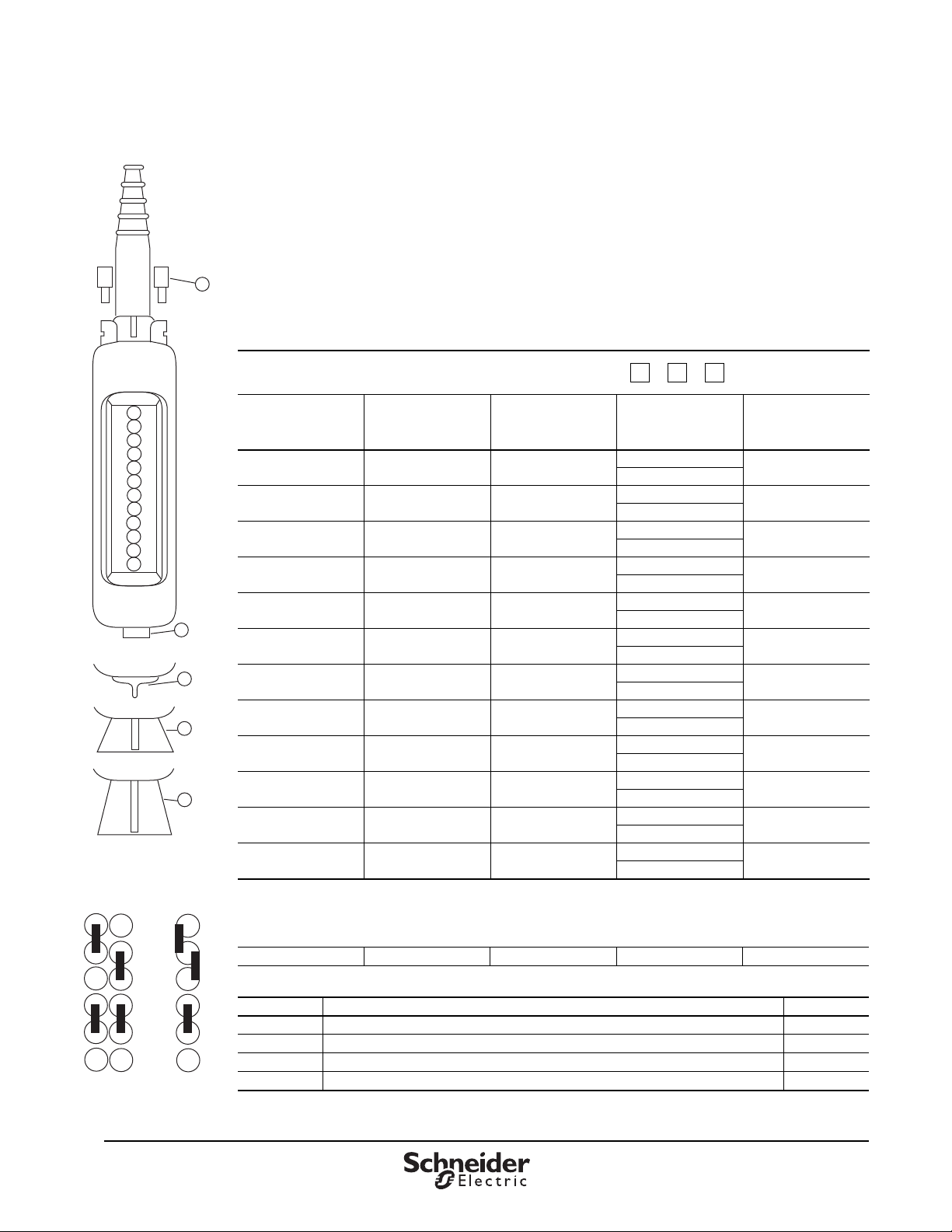
Type XACA Worksheet
Type XACA Worksheet
Use this worksheet to assist in component selection. Custom orders for XACA pendant stations must
be placed through the Product Selector in Quote to Cash. There is a 10% charge for assembly.
XACA Order Guide Instructions
Custom built pendant stations
14
1. Determine the number of operators needed, then choose an enclosure with a corresponding number of holes.
2. Select the type of operator, contact block, and appropriate nameplate for each function required. Refer to pages 8–11.
3. Check for special functions that may be required. These items could include mechanical interlocks, adapters for self-supporting
cable, lower support rings, protective guards, etc.
Catalog number
of enclosure
1
2
3
4
5
6
7
8
9
10
11
12
13
15
16
17
Functions
(optional)
Mechanical interlock
(draw a vertical line
between the 2 units to
be interlocked
1
2
3
4
5
6
7
8
9
10
11
[1]
)
Legends
XACA
Contact blocks and
pilot light bodies
Push button
Pilot light or
Blanking plug
12
Mechanical Interlock
(XACA009)
11
1
1
Mechanical interlock XACA009 Number of XACA009 required
Unit mounted in base of station (facing downwards)
2
2
3
3
44
5
5
66
Possible
Combinations
2
3
4
5
6
Impossible
Combinations
13
Attachments
Position Type Catalog No.
14 Adapters for self-supporting cable type BBAP (available only with cable sleeve Ø8–26 mm) XACB961
15 Lower support ring XACA971
16 Protective guard for base mounted selector switch or 40 mm emergency-stop push button XACA982
17 Protective guard for key switch XACA983
12
07/2013 © 2013 Schneider Electric
All Rights Reserved
Page 13
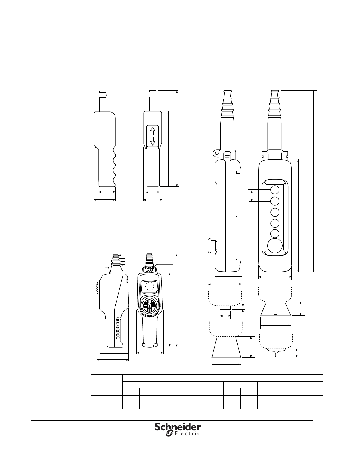
Type XACA Dimensions
1.9
48
2.36
60
Internal dia.
9 to 13 mm
1.66
42
1.97
50
8.5
216
10.87
276
2.75
70
3.55
90
3.15
80
B
A
XAC A982
Internal dia.
8 to 10 mm
11 to 14 mm
15 to 17 mm
18 to 22 mm
22 to 26 mm
300.5
11. 83
8 mm dia.
Internal dia.
16 to 18
13 to 15
10 to 12
7 to 9 mm
1.8
30
.35
8
1.1
28
1.3
33
3.15
80
2.25
57
3.15
80
.79
20
XAC A971
XAC A983
82
3.23
101
3.97
91
3.58
240
9.45
General Purpose Type
XACA••••
Small Hoist Type
XACA201, A205, and A207
Small Hoist
XACD
Pendant Stations
Type XACA Dimensions
© 2013 Schneider Electric
All Rights Reserved
Dimension
A 15.00 380 15.00 380 17.33 440 19.70 500 22.10 560 26.78 680
B 7.50 190 7.50 190 9.85 250 12.20 310 14.57 370 19.30 490
2346812
in. mm in. mm in. mm in. mm in. mm in. mm
Number of Holes
™
07/2013
13
Page 14
Pendant Stations
™
Lifetime
Enclosure
Warranty
®
Type SKYP General Information
Type SKYP General Information
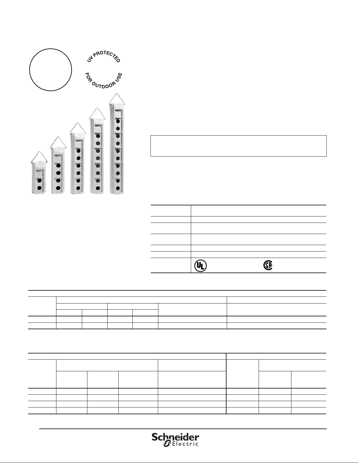
This line of pendant stations consists of polymeric enclosures (2–10 units),
push button units (1–5 speed), and laminated legend plates. All enclosures
have an extra single-unit space near the top that permits the installation of a
toggle switch, a Type SK operator or pilot light, or a warning label (see
Table 29 on page 15). All enclosures come standard with a stainless-steel
hanger bracket and internal strain-relief post. The enclosures are yellow
with a threaded opening in the top. The complete line is UL Listed and CSA
certified, with NEMA Type environmental ratings 1, 2, 3, 3R, 4, 4X, and 12
(NEMA 4 only with legend plates installed). To ensure Type 4X and 13
integrity, use only Type 4X and 13 operators or closing plates.
There is a 10% charge for assembly. To place a custom pendant order,
use the worksheet on 18 as a guide. Orders must be placed through the
Product Selector in Quote to Cash.
Type SKYP Specifications
Table 24: Type SKYP Specifications
Electrical
Ratings
Enclosure Type UL Type 1, 2, 3, 3R, 4, 4X, 12, and 13
Operating
Temperature
Storage
Temperature
Housing Material Polycarbonate
Cable Entry 1/2” NPT
Approvals
Table 25: Electrical Contact Ratings (Types SKRU2 through SKRU5)
AC—NEMA / UL Type B300
Inductive, 35% Power Factor Resistive, 75% Power Factor
Continuous Carrying Amperes
1
[1]
Volts
120 30 3600 3 360 5 5
240 15 3600 1.5 360 5 5
OSHA Regulation, Section 1910.170 Overhead and Gantry Cranes, limits the voltage at pendant push buttons to 150 Vac or 300 Vdc.
Make Break
AVAAVA
Table 26: Electrical Contact Ratings (Types SKRU1, 10, and 11)
AC—NEMA / UL Type A600 DC—Standard Duty, NEMA / UL Type P600
Inductive, 35% Power Factor
[1]
Volts
120 60 6 10 10 120 1.1 10
240 30 3 10 10 240 0.55 10
480 15 1.5 10 10 — — —
600 12 1.2 10 10 600 0.2 10
1
OSHA Regulation, Section 1910.170 Overhead and Gantry Cranes, limits the voltage at pendant push buttons to 150 Vac or 300 Vdc.
Make
Amperes
Break
Amperes
Continuous
Carrying Amperes
Make, Break, and Continuous
Types SKRU2–SKRU5: AC = NEMA / UL B300; DC = NEMA / UL P600
Types SKRU1, 10, 11: AC = NEMA / UL A600: DC = NEMA / UL P600
-30 C to +60 C (-13 F to +140 F)
-40 C to +70 C (-40 F to +158 F)
Resistive,
75% Power Factor
Carrying Amperes
File E78403
CCN NKCR
File LR 25490
Class 3211 03
Make, Break, and
Continuous Carrying Amperes
Inductive and Resistive
Volts
Make and
Break Amperes
Continuous
Carrying
Amperes
14
07/2013 © 2013 Schneider Electric
All Rights Reserved
Page 15
™
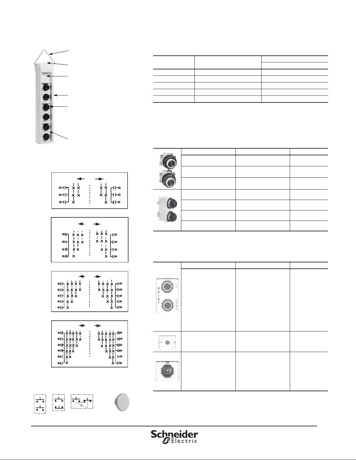
Hanger bracket
(Catalog no. 65091-061-01)
Threaded conduit hole
Space for toggle switch, a
Type SK operator, or a pilot light.
Use appropriate legend plates.
Type SKYP enclosure
Type SKRU1 through SKRU11
operators. Any Type SK pilot light or
operator can be mounted in this
enclosure. The enclosure depth
accommodates one Type KA1 through
KA6 contact blocks (total of two).
Type SKN2 legend plate
Terminals
87
2868-D30
C
1
2
2
1
SPEED POSITION
OFF
1
2
C
1
2
Terminals
Terminals
C
1
2
3
4
4
321
SPEED POSITION
OFF
2868-D31
89
12
3
4
Terminals
C
1
2
3
4
C
1
2
3
321
SPEED POSITION
OFF
2868-D29
88
1
2
3
Terminals
C
1
2
3
Terminals
Terminals
C
1
2
3
4
4
32
1
SPEED POSITION
OFF
2868-D32
90
1
2
3
4
Terminals
C
1
2
3
4
5
5
5
5
10
5
7
Figure 4: Multispeed Contact Symbols
(X = Contact Closed)
Closing Plate
Type SK52
Single Speed
Contact Symbols
Pendant Stations
Type SKYP Specifications
Table 27: Enclosures
Button
Size
Conduit Entrance
Size
Enclosure Only
Class 9001 Type
2¾"-14NPT SKYP2
4 ¾"-14 NPT SKYP4
61"-11½ NPT SKYP6
8 1¼"-11½ NPT SKYP8
10 1¼"-11½ NPT SKYP10
1
Class 9001 SK push-to-test pilot lights, remote-test pilot lights, and pote nti ometers do not fi t in
these enclosures.
2
Assembled pendant stations consist of an enclosure, operators, and le gend plates. The price of
the total station consists of the prices of the individual components, plus a 10% charge for
assembly. To place a custom pendant order, use the worksheet on 18 as a guide. Orders must
be placed through the Product Selector in Quote to Cash.
Table 28: Push Button Units (2 Buttons per Unit)
Description Contact Symbol (Figure 4) Class 9001 Type
Single Speed—
Momentary, Interlocked
Single Speed—
Momentary, Non-Interlocked
Single Speed—
Maintained, Interlock
Two Speed—
Momentary, Interlocked
Three Speed—
Momentary, Interlocked
Four Speed—
Momentary, Interlocked
Five Speed—
Momentary, Interlocked
1
Types SKRU 1, 10, and 11 include Type KA contact blocks.
Types SKRU 2–5 are factory enclosed contact blocks.
Boot for SKRU 2–5 = 9001KU37; boot for SKRU 1, 10, 11 = 9001KU1
7 SKRU1
5 SKRU10
10 SKRU11
87 SKRU2
88 SKRU3
89 SKRU4
90 SKRU5
[1, 2]
[1]
© 2013 Schneider Electric
All Rights Reserved
Table 29: Legend Plates
Where Used Marking Class 9001 Type
Blank-Blank
Hoist: Up-Down
Trolley: East-West
Trolley: Fwd.-Rev.
Trolley: North-South
For SKRU1 through
SKRU11
With Toggle Switch
[2]
Top Space of Enclosure
With Type SK Operator or
Pilot Light
[4]
in
Top Space of Enclosure
1
Maximum of 19 characters on each si de .
2
Available as Class 9001 Type SKSTS1—includes boot for NEMA Type 4X.
3
Includes legend plate, gasket, and ground plate to be used with toggle switch.
4
See Class 9001 Type SK on page 18.
5
Tri-laminated legend plate with a yellow or red background on a black core.
Bridge: Fwd.-Rev.
Bridge: East-West
Bridge: North-South
Start-Stop
Reset-Stop
Aux Hoist: Up-Down
Power: On-Off
Specify Marking
Blank
in
Off-On
On-Off
Specify Marking
Blank
On
Off
Emerg. Stop
Run
Power On
Off-On
Specify Marking
SKN200
SKN201
SKN202
SKN203
SKN204
SKN205
SKN206
SKN207
SKN208
SKN209
SKN210
SKN211
SKN299
SKN500
SKN544
SKN545
SKN599
SKN100
SKN103
SKN104
SKN105
SKN124
SKN138
SKN144
SKN199
07/2013
[1]
[1]
[3]
[3]
[3]
[3]
[5]
[5]
15
Page 16
Pendant Stations
™
Type SKYP Specifications
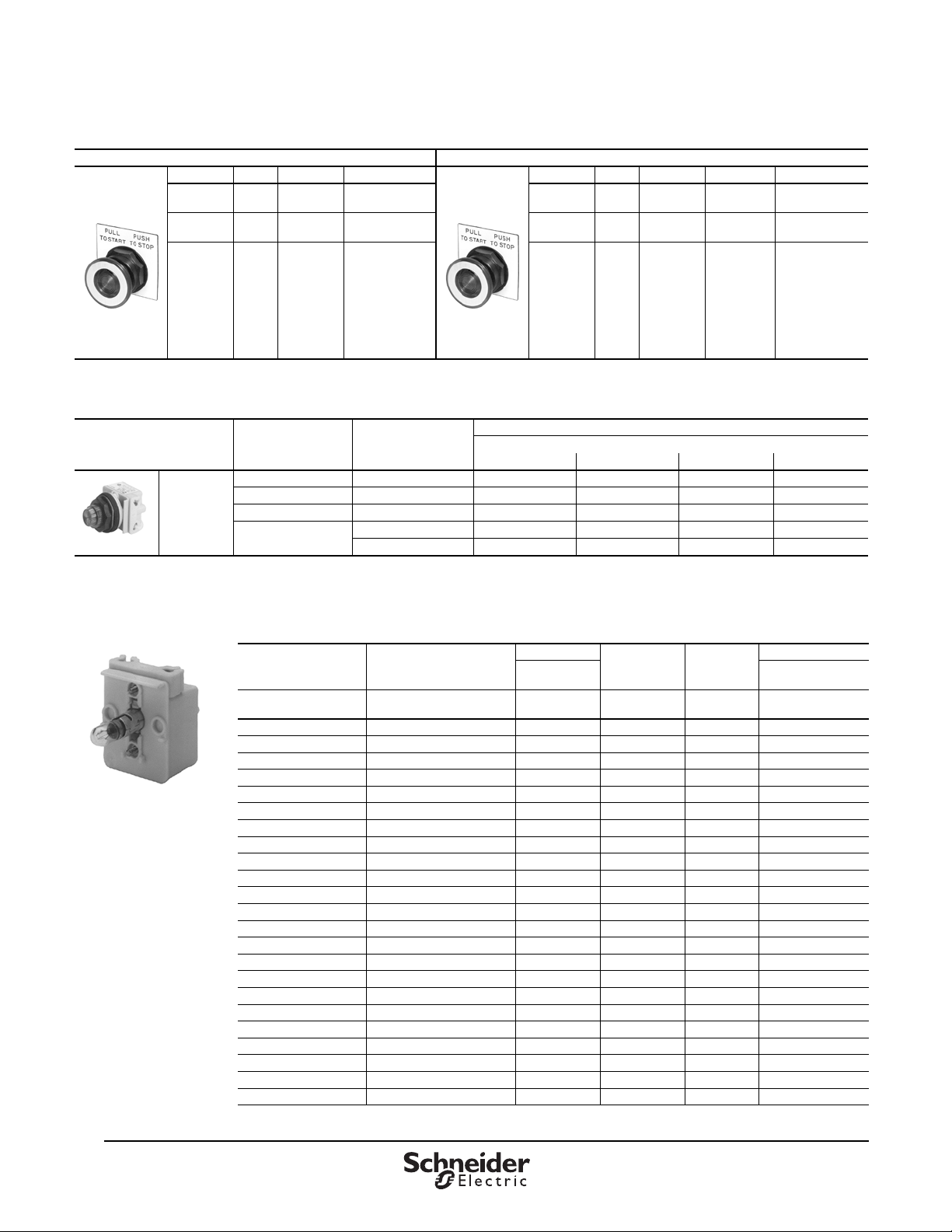
Table 30: Non-Illuminated and Illuminated Push Buttons
Non-Illuminated Illuminated
Description Color Color Code Class 9001 Type Description Color Color Code Voltage Class 9001 Type
2 Position Red R SKR9R 2 Position Red R
Maintained
Pull
Maintained
Push
1
Red knob available with “Push Emergency Stop” printed on the red knob. See Table 36 footnote for additional options.
[1]
Red
Black
Red
Green
Blue
Yellow
White
Orange
Clear
Amber
R SKR9R05
B
R
G
L
Y
SKR9
W
S
C
A
Table 31: Pilot Lights—UL Types 4, 4X, 13 / NEMA 4, 4X, and 13
Description Voltage Style
Red Fresnel Green Fresnel Other None
110–120 V, 50–60 Hz Transformer SKP1R31 SKP1G31 SKP1
Standard
Pilot Light
(Fresnel color
cap shown)
9001SKP1
1
Add the color code from Table 33. Example: SKP1 with an amber color Fresnel cap = SKP1A31.
2
The cap must be the same color as the LED light module. For example, use a green color cap for a green LED.
3
See Table 32 for voltage assembly code.
220–240 V, 50–60 Hz Transformer SKP7R31 SKP7G31 SKP7
24–28 Vac/Vdc Full Voltage SKP35R31 SKP35G31 SKP35
[2]
See Table 32 for other
voltages.
Transformer or LED
Full Voltage or Resistor SKP_R31
SKP_R31
Maintained
Pull
Maintained
Push
[3]
[3]
Red
Black
Red
Green
Blue
Yellow
White
Orange
Clear
Amber
SKP_G31
SKP_G31
[1]
R
—
R
G
L
Y
—
S
C
A
Class 9001 Type
Color Cap
[3]
[3]
SKP_
SKP_
120 Vac/Vdc
Full Voltage
24 Vac/Vdc
Full Voltage
24 Vac/Vdc
Full Voltage
[1]
[1]
[1]
[1, 3]
[1, 3]
SKR9P58R
SKR9P55R05
SKR9P55
SKP1
SKP7
SKP35
[3]
SKP
[3]
SKP
Table 32: Standard Light Modules for Pilot Lig hts
Voltage Description
All
Full Voltage (without
Bayonet Base Lamp)
Light Module
Class 9001
Type
KM40 40 — None
Voltage
Assembly
Code
Rating
6 Vac/Vdc Full Vo l ta g e KM31 31 0.9 VA 2550101020
6 Vac/Vdc LED Red KM31LR 31LR — 6508805201
6 Vac/Vdc LED Gre en KM31LG 31LG — 6508805203
6 Vac/Vdc LED Yel low KM31LY 31LY — 6508805202
12–14 Vac/Vdc Full Voltage KM32 32 1.2 VA 2550101037
12–14 Vac/Vdc LED Red KM32LR 32LR — 6508805201
12–14 Vac/Vdc LED Green KM32LG 32LG — 6508805203
12–14 Vac/Vdc LED Yellow KM32LY 32LY — 6508805202
24–28 Vac/Vdc Full Voltage KM35 35 1.2 VA 2550101002
24–28 Vac/Vdc LED Red KM35LR 35LR 0.28 VA 6508805210
24–28 Vac/Vdc LED Green KM35LG 35LG 0.28 VA 6508805212
24–28 Vac/Vdc LED Yellow KM35LY 35LY 0.28 VA 6508805211
24–28 Vac/Vdc LED White KM35LW 35LW 0.28 VA 6508805214
24–28 Vac/Vdc LED Blue KM35LL 35LL 0.28 VA 6508805213
110–120 V, 50–60 Hz LED Red KM1LR 1LR — 6508805201
110–120 V, 50–60 Hz LED Green KM1LG 1LG — 6508805203
110–120 V, 50–60 Hz LED Yellow KM1LY 1LY — 6508805202
110–120 V, 50–60 Hz Transformer KM1 12.4 VA2550101020
110–120 V, 50–60 Hz Flashing KMF1 F1 0.85 VA 2550101036
120 Vac/Vdc Resistor KM38 38 3.0 VA 2550101027
120 Vac/Vdc Full Voltage KM38 38 3.0 VA 2550101027
120 Vac/Vdc LED Red KM38LR 38LR 1.4 VA
120 Vac/Vdc LED Green KM38LG 38LG 1.4 VA 6508805212
Replacement Lamp
Catalog No.
6508805210
Continued on next page
16
07/2013 © 2013 Schneider Electric
All Rights Reserved
Page 17
Pendant Stations
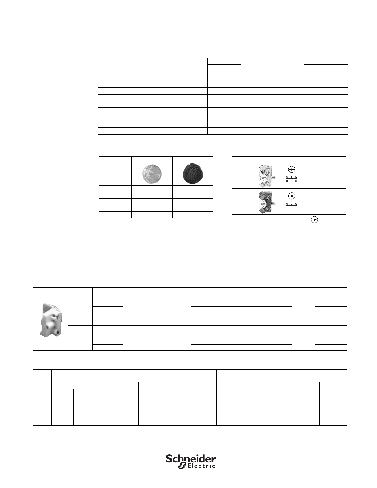
Table 33: Color Cap Codes
Color
Plastic Fresnel Plastic Domed
Amber A31 A9
Clear C31 C9
Green G31 G9
Red R31 R9
Yellow Y31 Y9
Table 34: Contact Blocks
Description Symbol
[1]
1
Both N.C. contacts are direct opening.
Class 9001 Type
Clear
Color
Cover
KA1
Red
Color
Cover
KA3
Type SKYP Specifications
Table 32: Standard Light Modules for Pilot Lights (continued)
Voltage Description
All
120 Vac/Vdc LED Yellow KM38LY 38LY 1.4 VA 6508805211
120 Vac/Vdc LED White KM38LW 38LW 1.4 VA 6508805214
120 Vac/Vdc LED Blue KM38LL 38LL 1.4 VA 6508805213
220–240 V, 50–60 Hz Tran sformer KM7 7 2.0 VA 2550101020
220–240 V, 50–60 Hz LED Red KM7LR 7LR — 6508805201
220–240 V, 50–60 Hz LED Green KM7LG 7LG — 6508805203
220–240 V, 50–60 Hz LED Yellow KM7LY 7LY — 6508805202
Full Voltage (without
Bayonet Base Lamp)
Light Module
Class 9001
Type
KM40 40 — None
Voltage
Assembly
Code
Rating
Replacement Lamp
Catalog No.
Table 35: Shallow Depth Light Modules For Type SK Control Units
Voltage Description
24–28
Vac/Vdc
110–120
Vac/Vdc
Table 36: Maximum Current Ratings For Control Circuit Contacts: Types KA1–KA6, KA21–25, KA31–35, KA1G–KA6G
Volts
1
© 2013 Schneider Electric
All Rights Reserved
Inductive (NEMA / UL Type A600), 35% Power Factor
Make Break
Amperes VA Amperes VA KA1
120 60 7200 6.0 720 10 10 125 0.55 0.55 — — 2.5
240 30 7200 3.0 720 10 10 250 0.27 0.27 — — 2.5
480 15 7200 1.5 720 10 10 — — — — — —
600 12 7200 1.2 720 10 10 600 0.10 0.10 — — 2.5
For additional Type SK push button operators (illuminated and non-illuminated), light modules, and contact blocks, see catalog 9001CT9601, Push Button and
Operator Interface Specifiers Guide. All illuminated push button operators must use a shallow depth l i ght module listed above. Only standard pilot lights and
non-illuminated selector switches can be used in Type SKYP enclosures.
Shallow Depth Light Modules For Type SK Con tro l Units
• UL Listed and CSA certified
• LED light modules use a lamp with a 7-element LED cluster that provides illumination similar to
incandescent illumination.
• With LED light modules, use either a clear color cap or a cap with the same color as the LED.
For Use With Single Lamp
Ill. Operators as Indicated
Full Voltage
LED Red KM55LR 55LR 0.5 6508805204
LED Green KM55LG 55LG 0.5 6508805206
LED Yellow KM55LY 55LY 0.5 6508805205
Full Voltage
LED Red KM58LR 58LR 0.5 6508805204
LED Green KM58LG 58LG 0.5 6508805206
LED Yellow KM58LY 58LY 0.5 6508805205
All 9001 SK
All 9001 SK
AC
Continuous
Carrying
Amperes
Continuous Amperes
Light Module
Class 9001 Type
KM55 55 1.2
KM58 58 3.0
Resistive, 75%
Power Factor
Make, Break, and
Volts
Voltage
Assembly Code
Rating
(VA)
Inductive and Resistive (NEMA Q600)
Make and Break
KA2
KA3
™
Replacement Lamps
ANSI No. Catalog No.
2550101002
757
2550101027
120MB
DC
KA4
KA5
KA6
Continuous
Carrying
Amperes
07/2013
[1]
17
Page 18
Pendant Stations
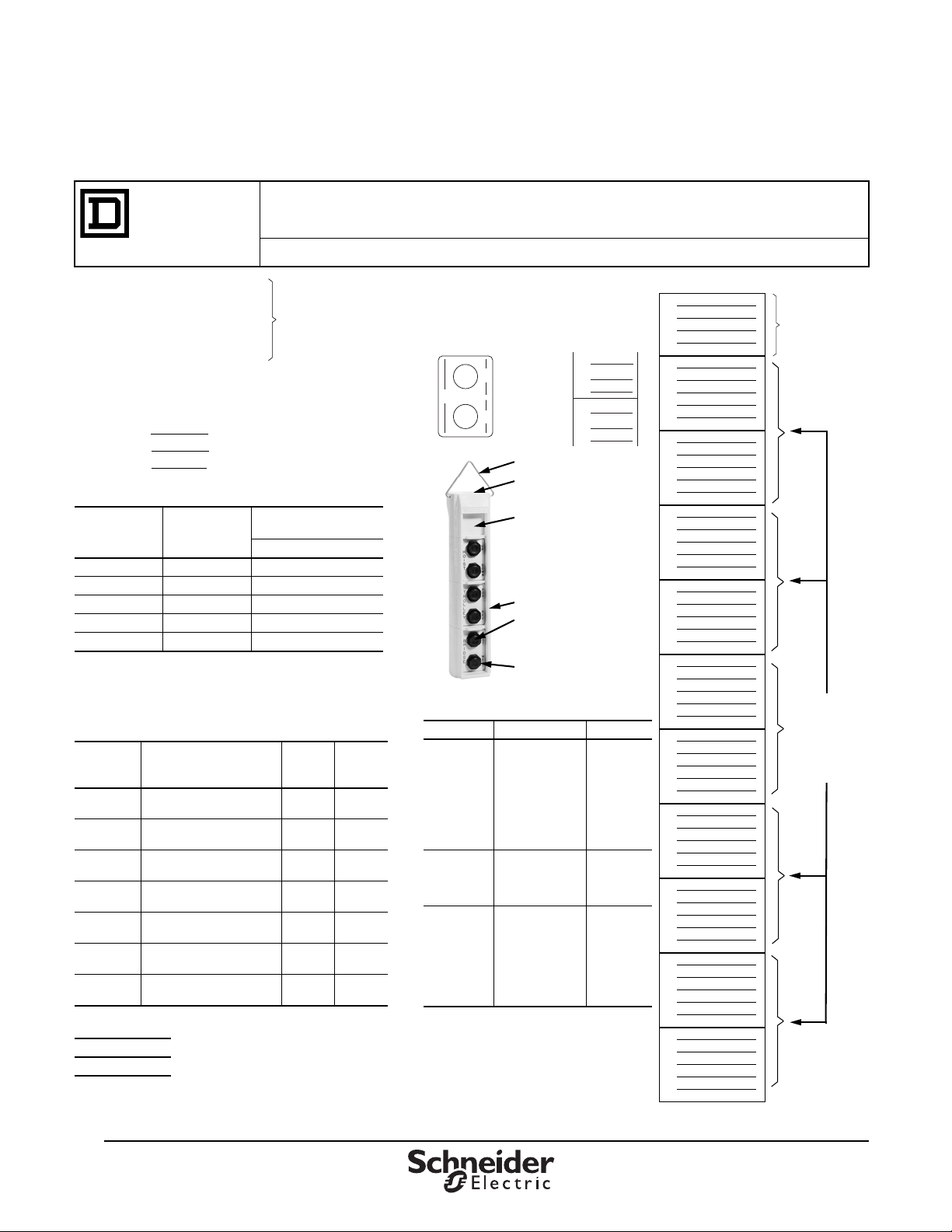
Type Number Key
1
2
3
1
2
3A)
B)
C)
1
2
3A)
B)
C)
1
2
3A)
B)
C)
1
2
3A)
B)
C)
1
2
3A)
B)
C)
1
2
3A)
B)
C)
1
2
3A)
B)
C)
1
2
3A)
B)
C)
1
2
3A)
B)
C)
1
2
3A)
B)
C)
Space for a
toggle switch ➀,
a Type SK
operator or pilot
light, or a
warning label.
Use SKN5 or
SKN1 legend
plates.
Type SKRU1
through SKRU
11 operators or
Type SK
operators and
Type SKN2
legend plate.
A
1
C
B
2
3
SKRU1
SKN201
1
2
3
SKRU1
SKN201
Hanger bracket
Threaded conduit hole
Space for toggle switch
➀,
a Type SK operator or pilot
light, or a warning label.
Use SKN5 or SKN1 legend
plates.
Type SKYP enclosure
Type SKRU1 through
SKRU11 operators.
Type SKN2 legend plate
Legend Plates—NEMA / UL 4X, 13
➀ Available as 9001SKSTS1
➁ Includes legend plate, gasket, and ground
plate to be used with toggle switch.
➂ Tri-laminated legend plate with a yellow or
red background on a black core.
➃ 19 characters each side.
▲ Class 9001 Type SK push-to-test pilot lights
and remote test pilot lights will not fit in these
enclosures.
Where Used Marking Type
For SKRU1
through
SKRU11
Blank–Blank
Hoist: Up-Down
Trolley: East-West
Trolley: Fwd.-Rev.
Trolley: North-South
Bridge: Fwd.-Rev.
Bridge: East-West
Bridge: North-South
Start–Stop
Reset–Stop
Specify Marking
SKN200 ➃
SKN201
SKN202
SKN203
SKN204
SKN205
SKN206
SKN207
SKN208
SKN209
SKN299
➃
With Toggle
Switch ➀ in
Top Space of
Enclosure
Blank
Off–On
On–Off
Specify Marking
SKN500 ➁
SKN544 ➁
SKN545 ➁
SKN599 ➁
With Type
SK Operator
▲ or Pilot
Light in Top
Space of
Enclosure
Blank
On
Off
Emerg. Stop
Run
Power On
Off-On
Specify Marking
Specify Marking
(Red Background)
SKN100 ➂
SKN103
SKN104
SKN105
SKN124
SKN138
SKN144
SKN199
➂
SKN199R ➂
When the operator and the legend plate use 2 adjacent
holes, specify the same catalog numbers in both
locations. Example:
Type SKYP Worksheet
Type SKYP Worksheet
Control
Products
Use this worksheet to assist in component selection.
SKYP Custom Pendant orders must be placed through the Product Selector in Quote to Cash.
There is a 10% charge for assembly.
1. Operator or Closing Plate.
Example: SKRU1
2. Legend Plate Type Number
Example: SKN201
3. Legend Plate Marking ▲
Used Only if Special Marking is Required
Example:
Line 2 = SKN299
Line 3 = A.) Hoist
B.) FWD
C.) REV
Enclosures—NEMA 4X, 13
Button
Size
2 ¾" -14 NPT SKYP20
4 ¾" -14 NPT SKYP40
6 1" -14 NPT SKYP60
8 1¼" -11½ SKYP80
10 1¼" -11½ SKYP100
▲ Assembled pendant stations consist of an enclosure,
operators, and legend plates. The price of the total station
consists of the price of each individual component plus a
10% charge for assembly.
Push Button Units—NEMA / UL 4X, 13
Number of
Buttons
per Unit
2
2
2
2
2
2
2
CLOSING PLATE
Type
SK52
18
07/2013 © 2013 Schneider Electric
Conduit
Entrance
Size
Description
Single Speed—
Momentary, Interlocked
Single Speed—
Momentary, Non-Interlocked
Single Speed—
Maintained, Interlocked
Two Speed—
Momentary, Interlocked
Three Speed—
Momentary, Interlocked
Four Speed—
Momentary, Interlocked
Five Speed—
Momentary, Interlocked
Enclosure for
Assembled Station ▲
Contact
Symbol
Type
7 SKRU1
5 SKRU10
10 SKRU11
87 SKRU2
88 SKRU3
89 SKRU4
90 SKRU5
Type
Class 9001 Type SKYP -________
All Rights Reserved
Page 19
Pendant Stations
68
2.68
102
4.00
111
See Table 34 for NPT Size
4.38
54.48
2.15
A
54
2.12
110
4.33
122
4.79
59
2.32
84
3.31
89
3.50
52
2.04
89
3.49
3.19
81
7.37
187
Dual Dimensions
inches
mm
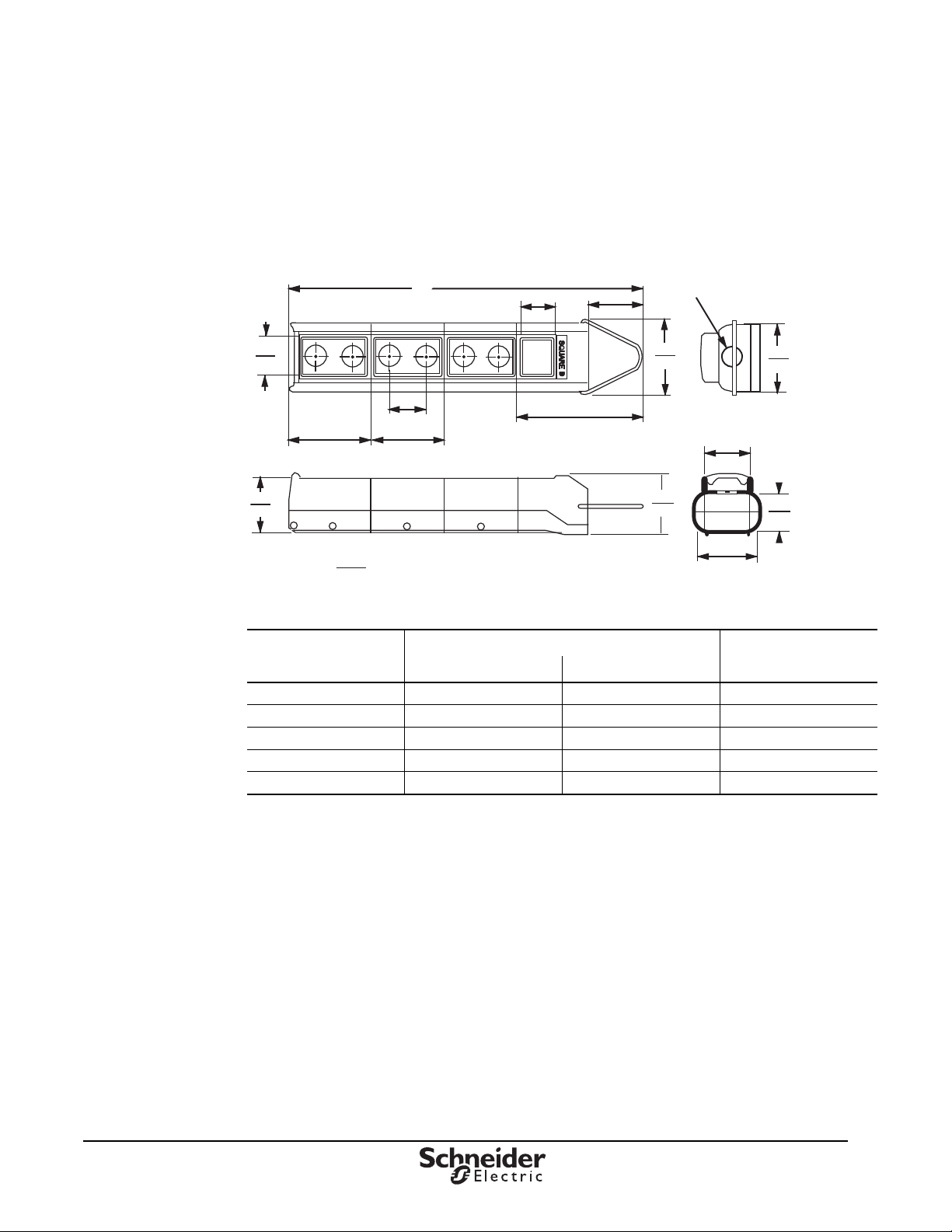
Type SKYP Dimensions
Type SKYP Dimensions
Class 9001 Type SK push-to-test pilot lights and remote-test pilot lights and potentiometers
do not fit in these enclosures. Standard pilot lights do fit in these enclosures. For illuminated operators
in the SKYP pendant station, the shallow depth light module (9001KM55 or 9001KM58) must be used.
Figure 5: Type SKYP Dimensions
Table 37: Approximate Dimensions
Number of Holes
Per Unit
2 11.70 297 ¾" -14
4 16.03 407 ¾" -14
6 20.36 517 1" -11 ½
8 24.69 627 1¼" -11½
10 29.02 737 1¼" -11½
© 2013 Schneider Electric
All Rights Reserved
in. mm NPT
Dimension A Conduit Opening
™
07/2013
19
Page 20

Pendant Stations
Type SKYP Dimensions
INDEX
2550101002 15–16
2550101020
2550101027
2550101036
2550101037
6508805201
6508805202
6508805203
6508805204
6508805205
6508805206
6508805210
6508805211
6508805212
6508805213
6508805214
BW90, BW100 2
DL1CB006
DL1CE012
DL1CE024
DL1CE048
DL1CE130
DL1CJUS0063
DL1CJUS0064
DL1CJUS0065
DL1CJUS0123
DL1CJUS0124
DL1CJUS0125
DL1CJUS0243
DL1CJUS0244
DL1CJUS0245
DL1CJUS1203
DL1CJUS1204
15–16
15–16
15
15
15–16
15–16
15–16
16
16
16
15
15–16
15
15–16
15–16
10
10
10
10
10
10
10
10
10
10
10
10
10
10
10
10
DL1CJUS1205
KA1
16
KA3
16
SKR9
15
SKR9P55
SKR9P55R05
SKR9P58R
SKR9R
SKR9R05
XACA009
XACA02
XACA03
XACA04
XACA06
XACA08
XACA12
XACA201
XACA205
XACA207
XACA913
XACA9411
XACA9412
XACA9413
XACA9414
XACA9416
XACA9419
XACA960
XACA971
XACA982
XACA983
XACB961
XACD21A0101
XACD21A0105
10
15
15
15
15
15
8
7
7
7
7
7
7
7
7
7
8
8
8
8
8
8
8
8
8, 11
8, 11
8, 11
8, 11
7
7
XACS101
XACS102
XACS103
XACS104
XACS105
XENG1191
XENG1491
XENG3781
XENG3791
XENT1192
ZA2BB2
8
ZA2BB4
8
ZA2BC44
ZA2BD2
8
ZA2BD3
8
ZA2BG4
ZA2BG5
ZA2BS14
ZA2BS44
ZA2BS54
ZA2BS74
ZA2BS834
ZA2BS844
ZA2BV03
ZA2BV033
ZA2BV04
ZA2BV05
ZA2BV053
ZA2BV06
ZB2BE101
ZB2BE102
ZB2BV006
ZB2BV007
8
8
7
7
7
7
7
7
7
7
7
7
8
8
8
8
8
8
8
8
8
8
8
8
8
7
7
8
8
ZB2BY2002
ZB2BY2004
ZB2BY2101
ZB2BY23
ZB2BY2303
ZB2BY2304
ZB2BY2305
ZB2BY2306
ZB2BY2307
ZB2BY2308
ZB2BY2309
ZB2BY2310
ZB2BY2311
ZB2BY2312
ZB2BY2313
ZB2BY2314
ZB2BY2321
ZB2BY2323
ZB2BY2326
ZB2BY2327
ZB2BY2328
ZB2BY2330
ZB2BY2334
ZB2BY2335
ZB2BY2336
ZB2BY2337
ZB2BY2338
ZB2BY2339
ZB2BY2341
ZB2BY2342
ZB2BY2343
ZB2BY2344
ZB2BY2345
10
10
10
10
10
10
10
10
10
10
10
10
10
10
10
10
10
10
10
10
10
10
10
10
10
10
10
10
10
10
10
10
10
ZB2BY2346
ZB2BY2365
ZB2BY2366
ZB2BY2367
ZB2BY2369
ZB2BY2370
ZB2BY2372
ZB2BY2376
ZB2BY2380
ZB2BY2381
ZB2BY2384
ZB2BY2387
ZB2BY2388
ZB2BY2389
ZB2BY2503
ZB2BY4001
ZB2BY4005
ZB2BY4101
ZB2SZ3
8
10
10
10
10
10
10
10
10
10
10
10
10
10
10
10
10
10
10
20
07/2013
© 2013 Schneider Electric
All Rights Reserved
Page 21

Pendant Stations
Type SKYP Dimensions
© 2013 Schneider Electric
All Rights Reserved
07/2013
21
™
Page 22

Schneider Electric USA, Inc.
1415 S. Roselle Road
Palatine, IL 60067 USA
www.schneider-electric.us
© 2013 Schneider Electric All Rights Reserved
Schneider Electric and Square D are trademarks owned by Schneider Electric Industries SAS or
its affiliated companies. All other trademarks are the property of their respective owners.
9001CT1001R07/13 Replaces 9001CT1001, 12/2010
07/2013
 Loading...