

Page 1
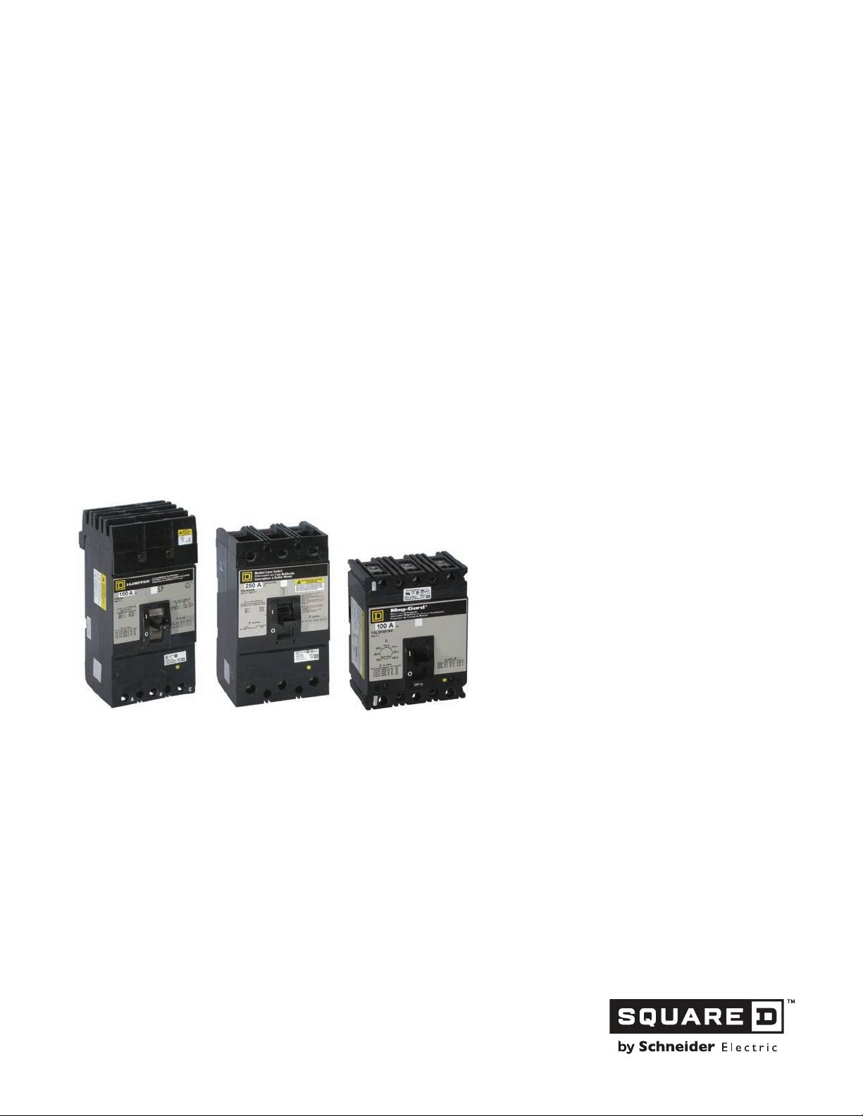
Legacy Thermal-Magnetic / Magnetic
Only Molded Case Circuit Breakers
Only Molded Case Circuit Breakers
(FA, KA, QB, LA, MA, NA Legacy Square D
Breakers)
Catalog
0601CT9101 R11/15
2015
Class 601
TM
Circuit
CONTENTS
Description . . . . . . . . . . . . . . . . . . . . . . . . . . . . . . . . . . . . . . . . . . . . . Page
Introduction. . . . . . . . . . . . . . . . . . . . . . . . . . . . . . . . . . . . . . . . . . . . . Page 5
100 Ampere Frame. . . . . . . . . . . . . . . . . . . . . . . . . . . . . . . . . . . . . . Page 25
225 / 250 Ampere Frame . . . . . . . . . . . . . . . . . . . . . . . . . . . . . . . . . Page 44
600 Ampere Frame. . . . . . . . . . . . . . . . . . . . . . . . . . . . . . . . . . . . . . Page 66
1200 Ampere Frame. . . . . . . . . . . . . . . . . . . . . . . . . . . . . . . . . . . . . Page 90
2000 / 2500 Ampere Frame . . . . . . . . . . . . . . . . . . . . . . . . . . . . . . . Page 98
Accessories . . . . . . . . . . . . . . . . . . . . . . . . . . . . . . . . . . . . . . . . . . Page 116
Page 2

Legacy Thermal-Magnetic / Magnetic Only Molded Case Circuit Breakers
© 1991–2015 Schneider Electric
All Rights Reserved
11/2015
2
Page 3

Legacy Thermal-Magnetic / Magnetic Only Molded Case Circuit Breakers
INTRODUCTION....................................................................................................................................5
Molded Case Circuit Breaker Types...................................................................................................6
Internal Operating Mechanisms..........................................................................................................8
Circuit Breaker Tripping Characteristics............................................................................................10
Construction......................................................................................................................................12
UL 489 Test Procedure......................................................................................................................13
Ratings for Molded Case Circuit Breakers.........................................................................................15
Return and Exchange Policy..............................................................................................................21
Catalog Numbers...............................................................................................................................22
100 AMPERE FRAME......................................................................................................................... 25
Description........................................................................................................................................25
Applications.......................................................................................................................................25
Selection Data...................................................................................................................................26
Dimensions........................................................................................................................................30
Tripping Curves.................................................................................................................................32
Let-through Curves............................................................................................................................42
225 / 250 AMPERE FRAME.................................................................................................................44
Description........................................................................................................................................44
Applications.......................................................................................................................................44
Selection Data...................................................................................................................................45
Dimensions........................................................................................................................................48
Tripping Curves.................................................................................................................................49
Let-through Curves............................................................................................................................64
600 AMPERE FRAME..........................................................................................................................66
Description........................................................................................................................................66
Applications.......................................................................................................................................66
Selection Data...................................................................................................................................66
Dimensions........................................................................................................................................67
Tripping Curves.................................................................................................................................68
Let-through Curves............................................................................................................................77
800 / 1000 AMPERE FRAME...............................................................................................................79
Description........................................................................................................................................79
Applications.......................................................................................................................................79
Selection Data...................................................................................................................................79
Dimensions........................................................................................................................................81
Tripping Curves..................................................................................................................................82
1200 AMPERE FRAME........................................................................................................................90
Description........................................................................................................................................90
Applications.......................................................................................................................................90
Selection Data...................................................................................................................................91
Dimensions.......................................................................................................................................92
Tripping Curves.................................................................................................................................93
2000 / 2500 AMPERE FRAME.............................................................................................................98
Description........................................................................................................................................98
Applications.......................................................................................................................................98
Selection Data...................................................................................................................................98
Dimensions......................................................................................................................................101
Tripping Curves...............................................................................................................................104
3
11/2015 © 1991–2015 Schneider Electric
All Rights Reserved
Page 4

Legacy Thermal-Magnetic / Magnetic Only Molded Case Circuit Breakers
ACCESSORIES..................................................................................................................................116
Factory and Field Installation Types................................................................................................116
Shunt Trip........................................................................................................................................119
Ground Fault Shunt Trip..................................................................................................................119
Undervoltage Trip............................................................................................................................121
Undervoltage Trip Time-delay Unit..................................................................................................122
Auxiliary Switch...............................................................................................................................123
Alarm Switch....................................................................................................................................124
Micrologic
Electrical Operators.........................................................................................................................127
Circuit Breaker Handle Accessories................................................................................................132
Circuit Breaker Cylinder Locks........................................................................................................132
Walking Beam Mechanical Interlock...............................................................................................133
Operating Mechanisms...................................................................................................................135
UL Listed Terminations....................................................................................................................136
Control Wire Terminations...............................................................................................................136
Lug Delete.......................................................................................................................................136
Power Distribution Connectors........................................................................................................139
Rear Connecting Studs....................................................................................................................139
I-Line
KA Insert Kit.....................................................................................................................................140
LC, LI, LE, LX and LXI Circuit Breaker Termination Clip Kit.............................................................141
Replacement Handles
Mechanical Key Interlock Adaptor Plate...........................................................................................141
Visi-blade
Sub-feed Lugs
TM
Ground Fault Module..................................................................................................125
TM
Accessories.......................................................................................................................140
.......................................................................................................................141
TM
Circuit Breakers............................................................................................................142
...................................................................................................................................142
4
11/2015 © 1991–2015 Schneider Electric
All Rights Reserved
Page 5

Legacy Thermal-Magnetic / Magnetic Only Molded Case Circuit Breakers
Introduction
For PowerPact
the Schneider Electric website,
This catalog introduces legacy thermal-magnetic circuit breakers, magnetic only circuit breakers, and
molded case switches. Most of the legacy devices are obsolete but will be in service for many years.
Catalog topics include the following:
TM
H-, J-, L-, M-, P- and R-Frame circuit breakers see class 611 and 612 catalogs on
• Construction standards
• Ratings and tripping characteristics
• Catalog numbers used when ordering (to specify the circuit breakers and accessories used with it)
• Return and exchange policies
The frame size sections contain application information on thermal-magnetic and magnetic only circuit
breakers and molded case switches. They are presented in subsections based on their amperage
ratings as shown below.
• 100 A Frame
• 225 / 250 A Frame
• 400 A Frame
• 600 A Frame
• 800 A Frame
• 1000 A Frame
• 1200 A Frame
• 2000 / 2500 A Frame
• Magnetic Only
• Molded Case Switches
The “Accessories” section contains the accessories used with thermal-magnetic circuit breakers,
magnetic only circuit breakers and molded case switches. Ordering information for the accessories is
also provided.
Circuit breakers are designed to protect electrical systems from damage caused by overloads, short
circuits, and ground faults. A molded case circuit breaker is defined by the National Electrical
Manufacturers Association
and enclosing housing of insulated material, designed to open and close a circuit by non-automatic
means, and to open the circuit automatically on a predetermined overcurrent, without injury to itself
when properly applied within its rating.”
®
(NEMA®) as, “... a device assembled as an integral unit in supporting
© 1991–2015 Schneider Electric
All Rights Reserved
11/2015
5
Page 6
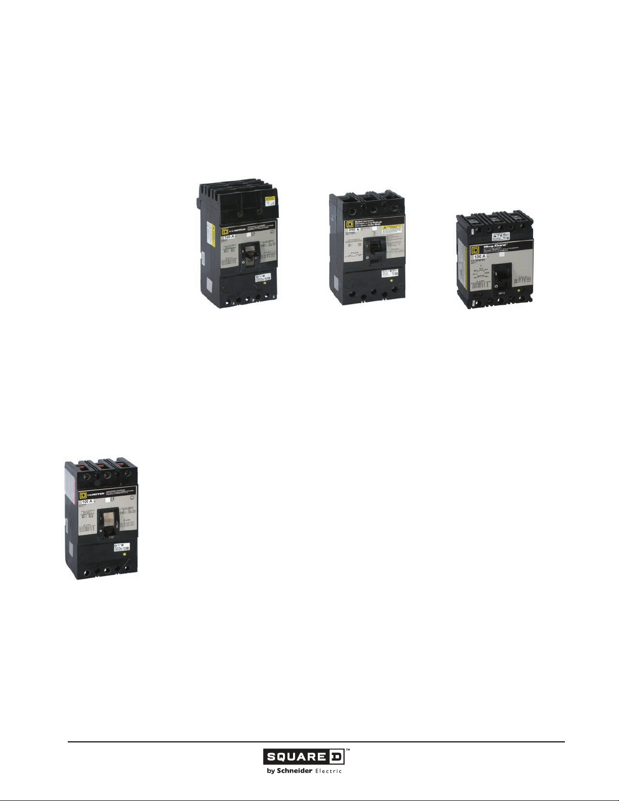
Legacy Thermal-Magnetic / Magnetic Only Molded Case Circuit Breakers
Molded Case Circuit Breaker Types
This catalog discusses the following types of molded case circuit breakers:
— Thermal-magnetic, including current limiting circuit breakers
TM
) circuit breakers
TM
brand current limiting circuit breakers are
TM
circuit breakers to limit both peak current and I2t let-
FIL
Current Limiting
Circuit Breaker
— Magnetic only (Mag-Gard
— Molded case switches
• Thermal-Magnetic Molded Case Circuit Breakers
Thermal-magnetic molded case circuit breakers are the most common overcurrent protection devices.
Their primary functions are to provide a means to manually open a circuit and automatically open a circuit
under overload or short circuit conditions. Thermal-magnetic circuit breakers use bimetals and
electromagnetic assemblies to provide overcurrent protection. Their characteristic inverse time tripping
under overload conditions is ideally suited for many applications varying from residential to heavy
industrial loads. For higher level (short circuit) overcurrents, instantaneous trip characteristics allow
molded case circuit breakers to interrupt with no intentional delay.
• Current Limiting Circuit Breakers
Current limiting circuit breakers are used for overcurrent protection and switching on ac systems where
high fault currents may be encountered. They have permanent trip units containing individual thermal
and magnetic trip elements in each pole like thermal-magnetic circuit breakers. But they go one step
further by limiting the amount of current that normally passes through a circuit breaker during a severe
fault on the circuit being protected. Schneider Electric
designed to take advantage of the electromagnetic repulsion created by closely spaced, parallel contact
arms carrying current in opposite directions. This repulsion, intensified by an “O” shaped magnet
surrounding the contact arms, causes the contacts to blow open in less than one millisecond under fault
conditions above 10 to 15 times the handle rating of the circuit breaker. This high speed contact
separation enhances the ability of the I-Limiter
through energy. UL
circuit breakers.
The following steps describe the short circuit interrupting process of current limiting circuit breakers at
fault levels within the current limiting range:
1. Contacts Part—The electromagnetic repulsion between the contact arms exceeds the spring
force that holds the contact arms together. The repulsion blows the contact open.
2. Limited Peak Current Reached—The intense magnetic field inside the “O” shaped magnet forces
the arc (between the opening contacts) into the stack plates.
3. Limiter Latch Holds Contacts Open—After Ip has been reached, the current must then be driven
to zero. At the same time this occurs, a specially designed limiter latch holds the contacts open
until interruption is complete.
4. Interruption Complete—To complete interruption, the arc voltage is sustained at a high enough
level to overcome source voltage and thereby drive the current to zero (complete interruption).
This requires a rapid rise in arc resistance and is accomplished by maintaining arc length while
quickly cooling the arc. Cooling the arc causes a loss of ionization which increases arc resistance.
®
requires that peak current and I2t let-through curves be available for current limiting
6
11/2015 © 1991–2015 Schneider Electric
All Rights Reserved
Page 7
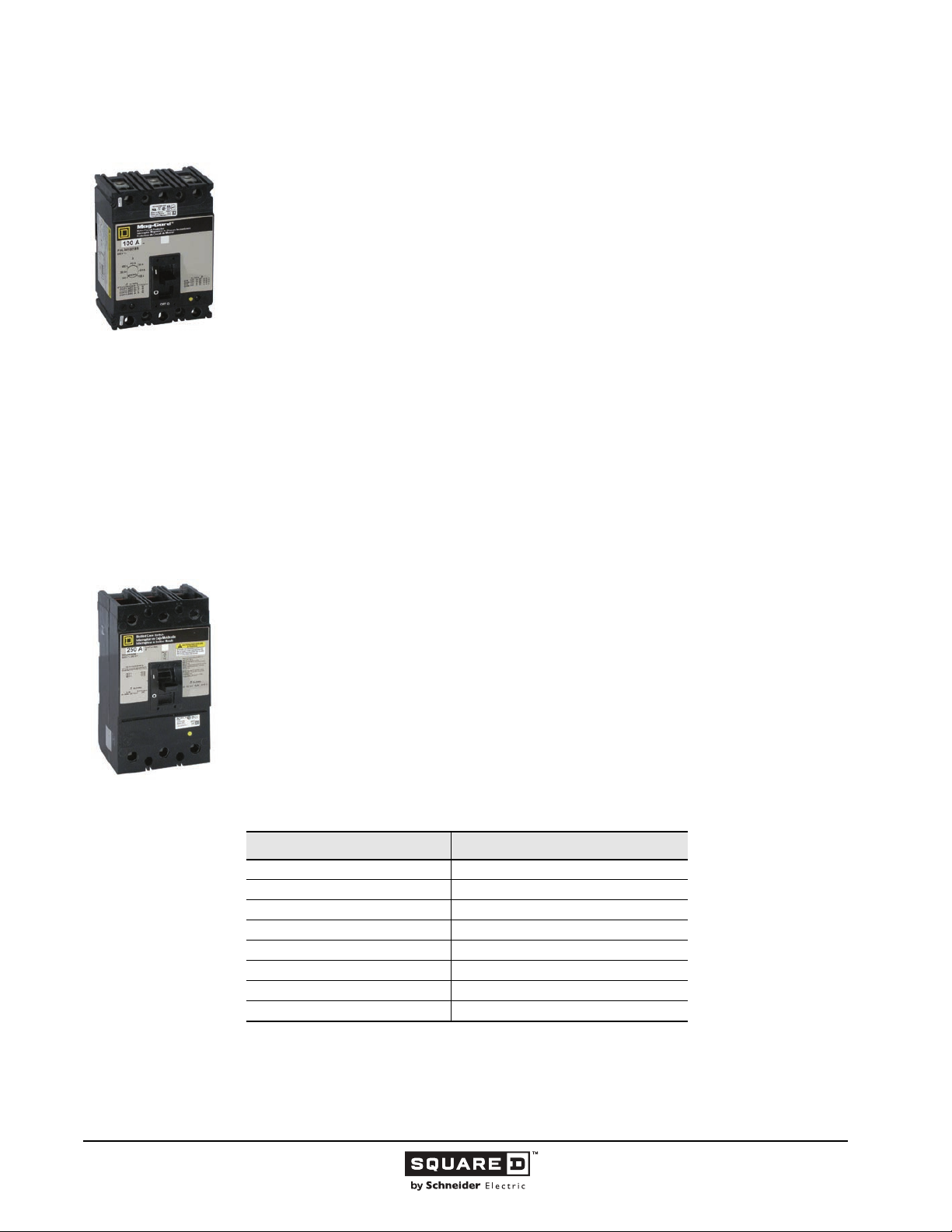
FAL
Magnetic Only
Circuit Breaker
KHL
Automatic Molded
Case Switch
Legacy Thermal-Magnetic / Magnetic Only Molded Case Circuit Breakers
• Magnetic Only Circuit Breakers
Mag-Gard magnetic only circuit breakers comply with National Electrical Code (NEC) requirements for
providing motor circuit protection when installed as part of a listed combination controller having motor
overload protection.
Mag-Gard instantaneous trip circuit breakers (often referred to as motor circuit protectors) are similar
in construction to thermal-magnetic circuit breakers. They are designed as disconnect devices for use
in combination with motor starters. Mag-Gard circuit breakers are built without thermal detection
elements (bimetals), therefore, they provide short circuit protection only. Mag-Gard circuit breakers
have an adjustable amperage pick up so they can be set to open instantaneously at current values
slightly above the motor starting inrush current. This setting coordinates the pick-up time-current
response of the Mag-Gard with the overload relay of the starter to give the best possible motor
protection. According to the 2002 NEC
for the starting current of the motor, the setting of an instantaneous trip circuit breaker shall be
permitted to be increased but shall in no case exceed 1300 percent of the motor full-load current for
other than Design E motors or Design B energy efficient motors and no more than 1700 percent of
full-load motor current for Design E motors or Design B energy efficient motors. Trip settings above
800 percent for other than Design E motors or Design B energy efficient motors and above 1100
percent for Design E motors or Design B energy efficient motors shall be permitted where the need
has been demonstrated by engineering evaluation. In such cases, it shall not be necessary to first
apply an instantaneous-trip circuit breaker at 800 percent or 1100 percent.” Current interrupting ratings
for these UL recognized components are established in combination with motor starters and properly
sized overload relays and contactors. Mag-Gard circuit breakers are tested in combination with
Schneider Electric starters per UL Standard 845.
• Molded Case Switches
Molded case switches are intended for use as disconnect devices only. UL Standard 489 requires
molded case switches to be protected by a thermal-magnetic circuit breaker (or fuse) of equivalent
rating. Molded case switches are labeled with their appropriate withstand ratings. Withstand rating is
defined as the maximum current, at rated voltage, that the molded case switch will withstand, without
damage, when protected by a circuit breaker (or fuse) with an equal continuous current rating.
Automatic molded case switches are similar in construction to thermal-magnetic circuit breakers,
except that the thermal detection element is not present. These switches open instantaneously at a
non-adjustable, factory preset, magnetic trip point calibrated to protect only the molded case
construction, they are more compact than conventional disconnect switches and accept electrical
accessories for added flexibility.
The following molded case switches are available from Schneider Electric:
Table 1: Molded Case Switches
®
, “Where the setting specified in Table 430.52 is not sufficient
1
© 1991–2015 Schneider Electric
All Rights Reserved
Circuit Breaker Frame Type
FH 100 A Frame
QB, QD, QG, QJ
See Class 612, 613, and 734 catalogs for other PowerPact and MasterpactTM circuit
breakers.
1
KH 250 A Frame
LH 400 A Frame
MH 600-1000 A Frame
NC 1200 A Frame
PH 2000 A Frame
PC 2500 A Frame
70–250 A Frame
11/2015
7
Page 8
Legacy Thermal-Magnetic / Magnetic Only Molded Case Circuit Breakers
Internal Operating Mechanisms
The following mechanisms allow the circuit breaker to operate:
— Thermal trip
— Magnetic trip
— Push-to-trip button
— Shunt trip
— Undervoltage trip
Note: Shunt trip and undervoltage trip are described in the Accessories section.
• Tripping Mechanism
The tripping mechanism is an assembly within the circuit breaker frame that causes the circuit breaker
to open automatically under sustained overload, short circuit, or high level ground fault conditions.
The tripping mechanisms in two and three-pole circuit breakers operate such that an overcurrent on
any given pole of the circuit breaker will cause all poles of the circuit breaker to open simultaneously. A
thermal and magnetic factory calibration test (with current) is performed on each pole of every circuit
breaker manufactured by Schneider Electric.
The sensing system of a thermal-magnetic circuit breaker is an integral part of the circuit breaker that
continually monitors the current flowing through the circuit breaker. It detects abnormal current
conditions and, depending on the magnitude of the current, initiates an inverse-time or an
instantaneous tripping response. This action causes the tripping mechanism to open the circuit
breaker contacts and interrupt current flow. The speed of the tripping process must be controllable and
inversely matched to the severity of the overcurrent. The ability of a particular circuit breaker to
interrupt a given level of overcurrent depends on the sensitivity of the circuit breaker.
Thermal-magnetic circuit breakers have two tripping elements.
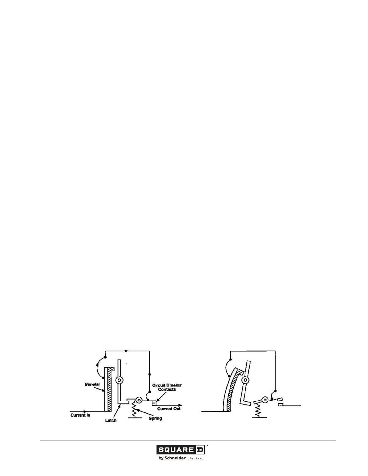
• Thermal Trip
The molded case circuit breaker thermal trip element is a root means squared (RMS) sensing device.
The bimetal thermal element is constructed from metals of dissimilar rates of expansion bonded
together. The thermal portion responds to overloads by reacting to the heat generated both by the
current flowing through the circuit breaker and by the heat contribution from the ambient conditions.
The bending force of the bimetal causes the circuit breaker to trip. The deflection of the bimetal is
predictable as a function of current and time. This is the inverse time tripping characteristics of the
thermal element (i.e., the tripping time decreases as the magnitude of the current increases).
Schneider Electric calibrates the thermal elements for a specific amperage rating, and they are not
field adjustable. The thermal trip elements are calibrated for 104 °F (40 °C) ambient temperature per
UL Standard 489.
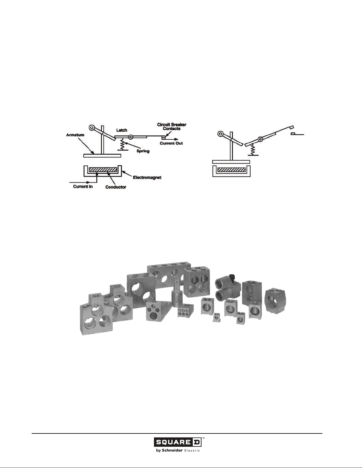
Figure 1: Thermal Trip Condition
Normal Condition Thermal Trip Condition
8
11/2015 © 1991–2015 Schneider Electric
All Rights Reserved
Page 9
Legacy Thermal-Magnetic / Magnetic Only Molded Case Circuit Breakers
• Magnetic Trip
The magnetic (instantaneous) trip element uses an electromagnetic assembly, in series with the load
current, to trip the circuit breaker instantaneously (with no intentional delay) at or above a
predetermined current value. During a short circuit of significant magnitude, the high level current
passing through the conductor rapidly increases the magnetic field of the electromagnet which attracts
the armature. As the armature is drawn toward the electromagnet, it initiates an unlatching action and
opens the circuit breaker contacts.
Figure 2: Magnetic Tip Condition
Normal Condition Magnetic Trip Condition
• Line and Load Connections
Thermal-magnetic circuit breakers, magnetic only circuit breakers, and molded case switches are
provided with factory installed UL listed mechanical-type aluminum alloy lugs suitable for either
aluminum or copper wire. In addition to mechanical lugs, Schneider Electric can supply copper
mechanical lugs, aluminum or copper Versa-Crimp
connectors. Circuit breakers can be ordered without lugs to accept bus connections.
TM
compression lugs, and power distribution
Figure 3: Mechanical and Versa-Crimp Lugs
Schneider Electric also offers I-Line circuit breakers, which feature plug-on connectors. They are
designed for easy installation and removal of the circuit breakers in our exclusive I-Line panelboards.
I-Line circuit breakers use “blow-on” type connectors. In case of a short circuit, in the circuit being
protected, the increased magnetic flux causes the plug-on connectors to grasp the panelboard bus
bars even tighter. These connectors are an integral part of the I-Line circuit breakers, as is the circuit
breaker mounting bracket.
• Push-To-Trip Button
Push-to-Trip is a standard feature of Schneider Electric molded case circuit breakers that allows the
circuit breaker to be manually tripped without exposure to live parts. The Push-to-Trip button is located
on the face of each molded case circuit breaker for ease of periodic operation.
© 1991–2015 Schneider Electric
All Rights Reserved
11/2015
9
Page 10
Legacy Thermal-Magnetic / Magnetic Only Molded Case Circuit Breakers
International I/O (ON/OFF) markings appear on the face of each Schneider Electric molded case
circuit breaker and molded case switch in addition to the standard ON/OFF markings to indicate handle
position. When tripped, the handle assumes a center position. To reset the breaker, the handle is
moved to the OFF position and then to the ON position. During normal on/off operation, the handle
opens and closes the circuit breaker contacts but does not exercise the tripping mechanism. Schneider
Electric suggests that the circuit breaker’s tripping mechanism be exercised at least annually. Use of
the Push-to-Trip system will also check:
— Alarm circuits
— Emergency circuits
— Motor sequencing operations
For maintenance information, application and field testing guides, contact the local Schneider Electric
Customer Information Center at
Circuit Breaker Tripping Characteristics
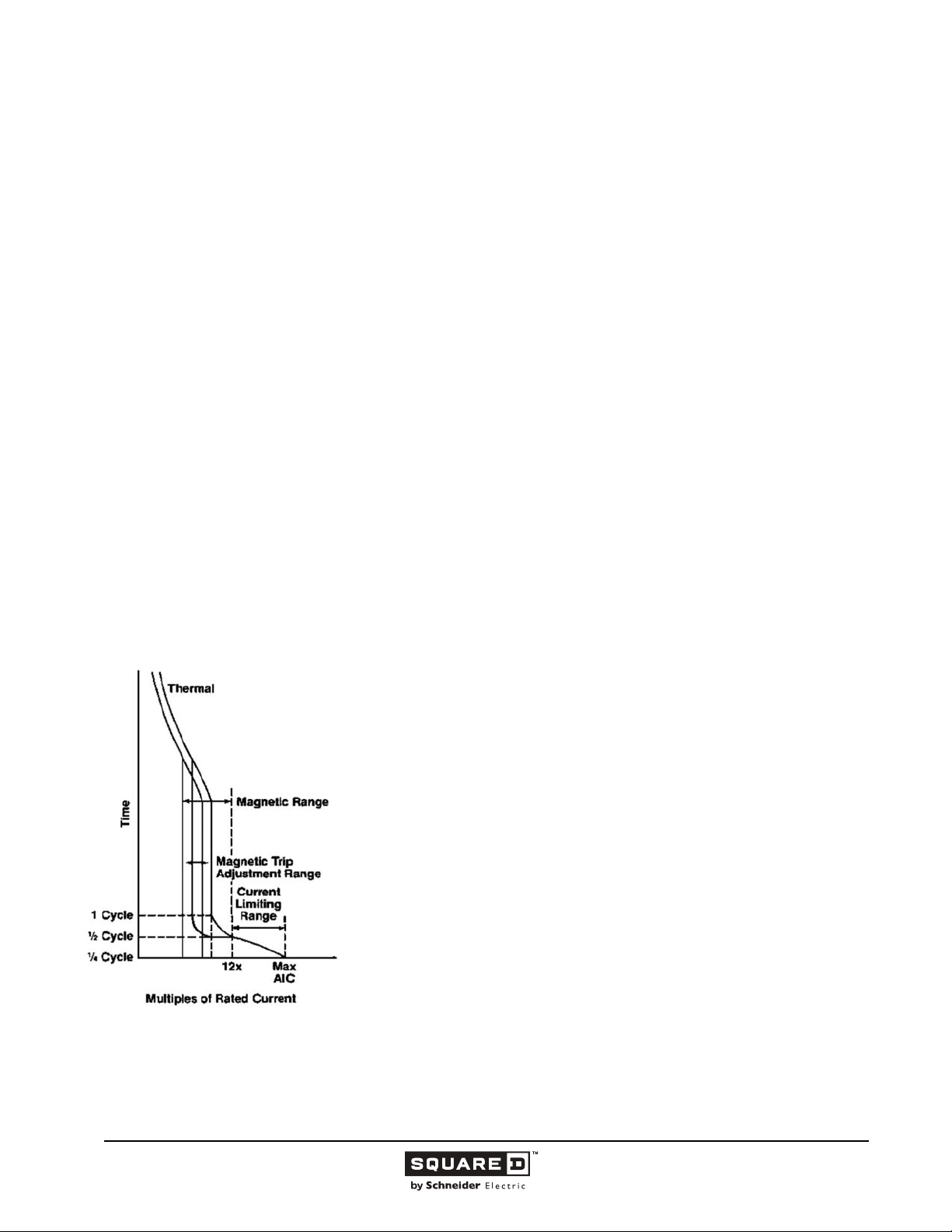
The tripping characteristics of thermal-magnetic molded case circuit breakers can be represented by a
characteristic tripping curve that plots tripping time versus current level. The curve shows the amount
of time required for a circuit breaker to trip for currents ranging from minor overloads to maximum
interrupting capacity.
• Thermal Tripping Characteristics
The left-hand portion of a tripping curve displays the circuit breaker’s thermal response. On low level
overcurrents, up to the magnetic tripping level, thermal tripping occurs when a bimetal in the circuit
breaker responds to heat associated with overcurrent. The bimetal deflects, unlatching the
mechanism, which causes the circuit breaker contacts to open. The larger the overcurrent, the faster
the circuit breaker operates to open the circuit (inverse time).
• Magnetic Tripping Characteristics
Figure 4: FI Characteristic Tripping Curve
The right hand portion of a tripping curve displays the magnetic tripping response of the
circuit breaker. This takes place when overcurrents of sufficient magnitude operate an
internal magnetic armature that unlatches the tripping mechanism. Magnetic tripping
occurs with no intentional delay.
For example, the FI circuit breaker time current characteristic tripping curve shows the
tripping response of the circuit breaker for currents ranging from minor overloads to
maximum interrupting capacity.
10
11/2015 © 1991–2015 Schneider Electric
All Rights Reserved
Page 11
Legacy Thermal-Magnetic / Magnetic Only Molded Case Circuit Breakers
• Circuit Breaker Coordination
To determine what level of coordination exists between molded case circuit breakers, a comparison of
circuit breaker characteristic tripping curves is necessary.
A coordination study is an organized effort to achieve optimum electrical distribution system protection
by determining the appropriate frame sizes, ampere ratings, and settings of overcurrent protective
devices. When an overcurrent within the coordination limits occurs in a distribution system, only the
protective device nearest the overload or fault opens. Lack of coordination between overcurrent
devices can result in upstream devices opening and interrupting electrical distribution in other parts of
the system.
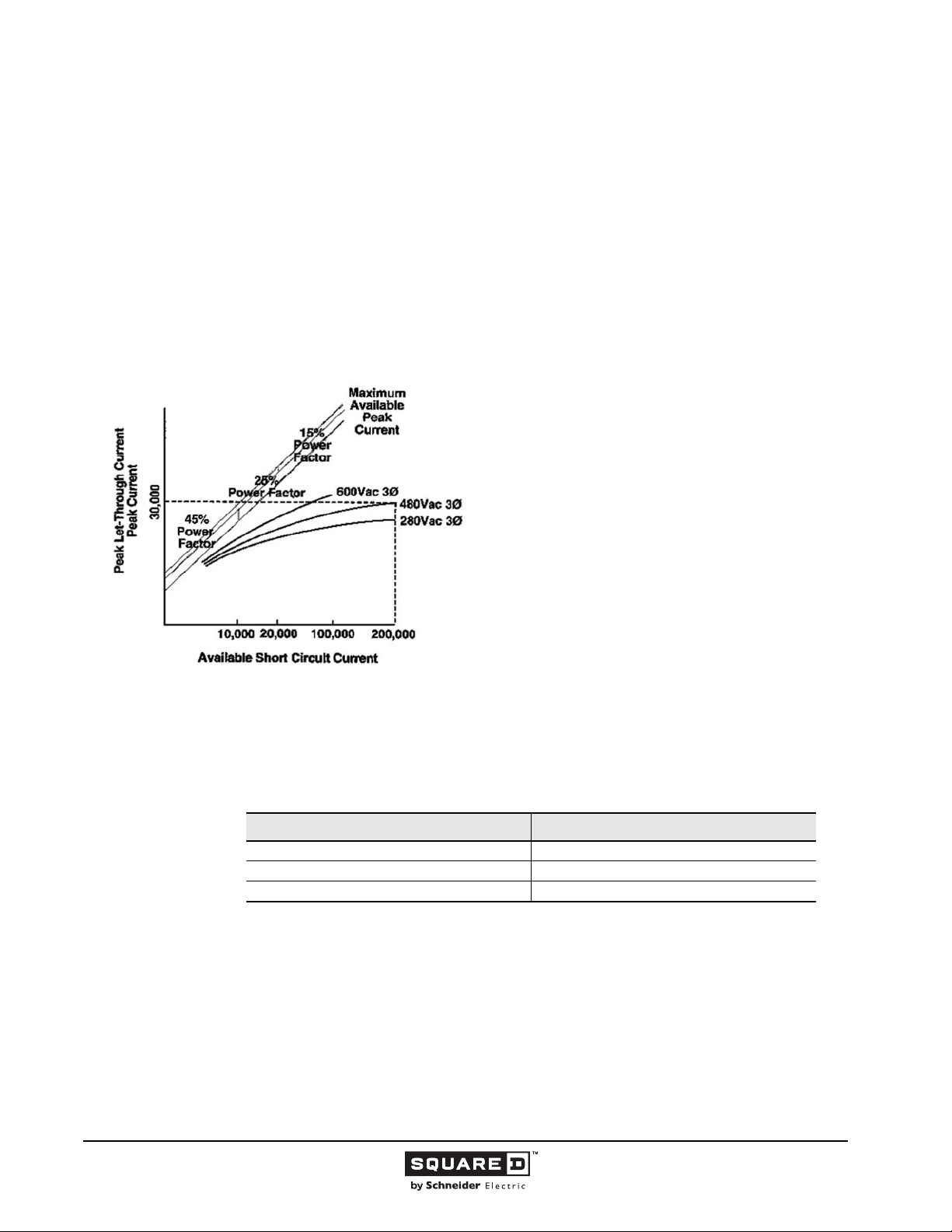
• Let-through Current Curves
Figure 5: Maximum Instantaneous Let-through Current
Let-through current curves show the extent to which a current
limiting circuit breaker limits the peak current that could flow
during a short circuit. On these curves, the slanting straight
lines marked 15%, 25% and 45% power factor show the
maximum theoretical peak currents that could flow in a faulted
circuit having that particular short circuit power factory—with
NO current limiting device in the circuit.
Short circuits which produce high fault currents typically are associated with low short circuit power
factors; that is, high X/R ratios. Since different portions of a system will exhibit various available fault
levels and power factors associated with those levels, UL has established that the following power
factors be used in short circuit testing:
Table 2: Power Factors in Short Circuit Testing
Since the peak current let-through curves for the I-Limiter current limiting circuit breakers were derived
from tests at the current levels and power factors indicated, the degree of current limitation is
expressed by the differential between the maximum available peak current and the actual test letthrough peak current.
The curves extend from the threshold of current limitation through the maximum interrupting rating of
the current limiting circuit breaker.
© 1991–2015 Schneider Electric
All Rights Reserved
Test Current RMS Symmetrical (Amperes) Power Factor (%)
10,000 or Less 45–50
10,000–20,000 25–30
Over 20,000 15–20
11
11/2015
Page 12
Legacy Thermal-Magnetic / Magnetic Only Molded Case Circuit Breakers
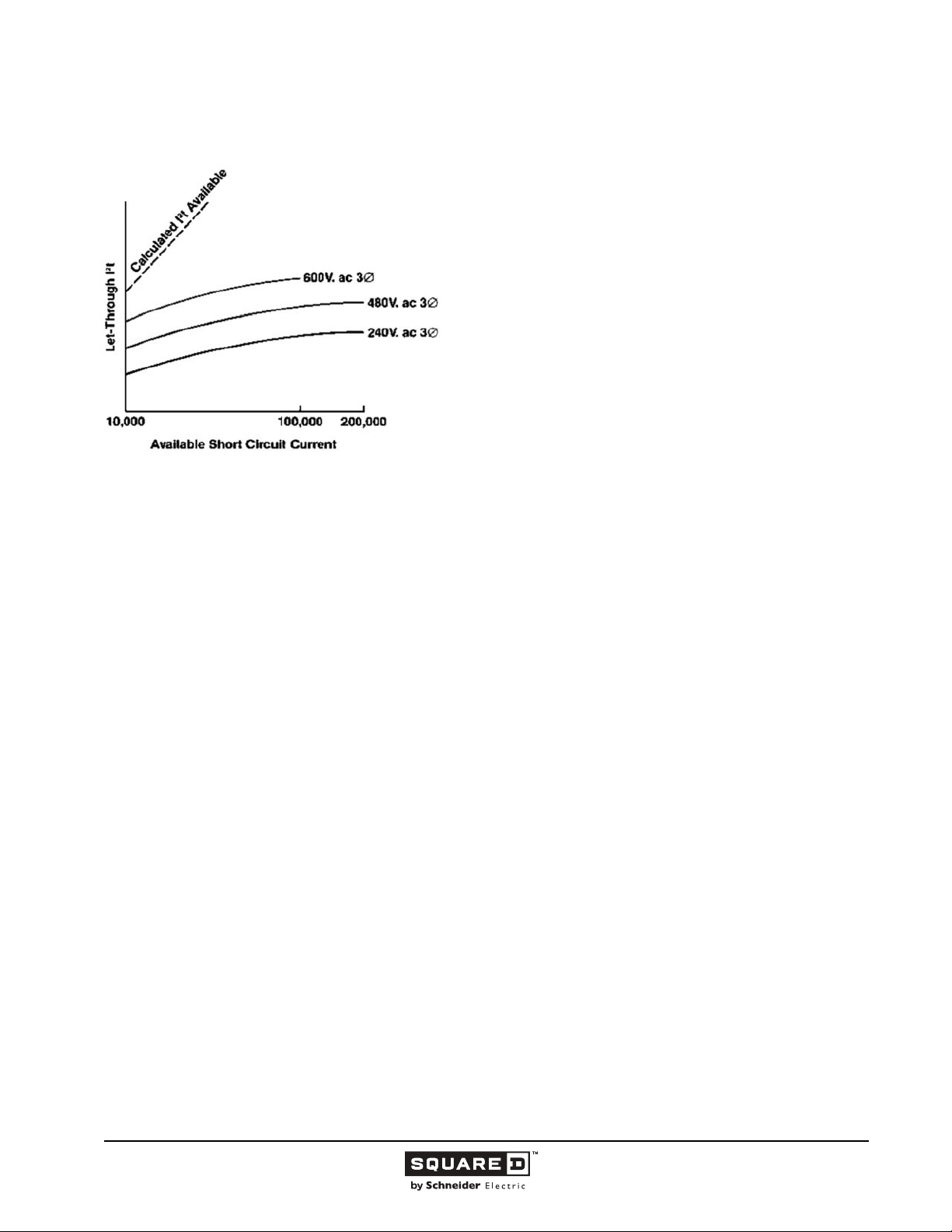
Figure 6: Maximum Let-through I
Construction
Thermal-magnetic circuit breakers are manufactured and tested according to the following standards
and files:
• Underwriters Laboratories Inc. (UL) Listed to UL489 Standard, File E10027,
• National Electrical Manufacturers Association (NEMA) AB-1 Standard,
• Canadian Standards Association (CSA) Certified to CSA C22.2 No. 5-02 Standard, File LR7551,
• International Electrotechnical Commission (IEC) 60947-2 Standard,
• Federal Specification W-C-375B/GEN as Class 11a, 11b; 12a, 12b; and 13a, 13b.
Magnetic only circuit breakers are manufactured and tested according to the following standards and
files:
• Underwriters Laboratories Inc. (UL) Recognized to UL489 Standard, File E10027,
• Canadian Standards Association (CSA) Certified to CSA C22.2 No. 5-02 Standard, File LR32390.
Molded case switches are manufactured and tested according to the following standards and files:
• Underwriters Laboratories Inc. (UL) Listed to UL489 Standard, File E33117 or E87159,
• Canadian Standards Association (CSA) Certified to CSA C22.2 No. 5-02 Standard, File LR32390
or LR40970.
Note: Circuit breakers are to be applied by guidelines detailed in the NEC and other local electrical
codes.
• Specifications
Cases for molded case circuit breakers are constructed of a glass-reinforced insulating material that
provides high dielectric strength. Current carrying components are isolated from the handle and
accessory mounting area. The handle position indicates whether the circuit breaker is OFF, ON or
tripped.
Schneider Electric molded case circuit breakers:
• Have common tripping of all poles,
• Are equipped with a Push-To-Trip button to manually trip the circuit breaker,
• Can be mounted and operated in any position,
• Are fully tested, UL listed, CSA certified, and IEC rated for reverse connection without restrictive
“LINE” or “LOAD” markings.
2
t Energy
Let-through I
circuit breaker limits energy let-through under short circuit
conditions. The theoretical I
current can be calculated. At 100,000 A rms, this would be 83 x 10
2
A
seconds for ½ cycle if NO CURRENT LIMITING DEVICE WERE
IN THE CIRCUIT. In contrast, the curves show that with the same
level of 100,000 rms symmetrical short circuit amperes available,
the 100 A current limiting circuit breaker would limit the energy flow
0.62 x 10
240 volts.
2
t curves show the extent to which the current limiting
2
t let-through of symmetrical sinusoidal
6 A2
seconds at 480 volts or 0.27 x 10⁶ A2 seconds at
6
12
11/2015 © 1991–2015 Schneider Electric
All Rights Reserved
Page 13

Legacy Thermal-Magnetic / Magnetic Only Molded Case Circuit Breakers
• Tripping System
Schneider Electric thermal-magnetic molded case circuit breakers have a permanent trip unit that
contains a factory preset thermal trip element and a magnetic trip element in each pole. The thermal
trip element is rms sensing. In circuit breakers with frame sizes greater than 100 A, the magnetic trip
element is field adjustable. A single adjustment simultaneously adjusts the instantaneous trip point in
each pole.
• Terminations
All factory installed mechanical type lugs are UL listed to accept solid or stranded conductors and can
be used with wire rated at 60° C (sized according to the NEC 140 °F (60 °C) temperature rating).
167 °F (75 °C) and 90° C (sized according to the NEC 167 °F (75 °C) temperature rating). Most molded
case circuit breakers are UL listed to accept field installable mechanical type and compression type
lugs.
• UL Requirements
A UL label on a Schneider Electric molded case circuit breaker indicates that the circuit breaker meets
the requirements of UL Standard 489 for circuit breakers.
A UL label also means the production procedure is monitored by UL inspectors for continuing
conformance to UL performance requirements. These requirements are based on sound engineering
principles, research, records of test and field experience, and information gathered from users and
inspection authorities. These requirements are subject to revision as necessary.
• UL HACR Type
All UL 489 listed molded case circuit breakers are HACR type.
UL 489 Test Procedures
• Limited Available Fault Current Tests
UL requires a series of tests on a single set of sample circuit breakers for compliance with
UL Standard 489. The tests for thermal-magnetic circuit breakers are described below.
Since molded case switches are derivatives of molded case circuit breakers, some testing of switches
is identical to that for circuit breakers. These tests include a 600% overload performance test:
— 200% Thermal Calibration
Each pole of the circuit breaker must trip within a specified time limit when carrying 200% of its
continuous current rating.
— 135% Thermal Calibration
With all poles connected in series, the circuit breaker must trip within a specified time limit when
carrying 135% of its continuous current rating.
— Magnetic Calibration
If the circuit breaker has an adjustable magnetic tripping means, then it must trip within a specified
percentage of the marked tripping current.
— Overload
The circuit breaker is operated making and breaking 600% of its continuous current rating, but not
less than 150 A.
For circuit breakers through 1600 A, the number of 600% operations is 50. For larger circuit
breakers to 4000 A, the number of operations is 25.
— Temperature Rise
While carrying 100% of rated current at a 104 °F (40 °C) ambient temperature and mounted in
open air, the circuit breaker is checked for temperature rise on a wring terminal. The temperature
on the terminal shall not exceed a 122 °F (50 °C) rise above ambient temperature and must be
within specified limits.
— Endurance
The circuit ibreaker must successfully complete the following number of switching operations.
© 1991–2015 Schneider Electric
All Rights Reserved
11/2015
13
Page 14
Legacy Thermal-Magnetic / Magnetic Only Molded Case Circuit Breakers
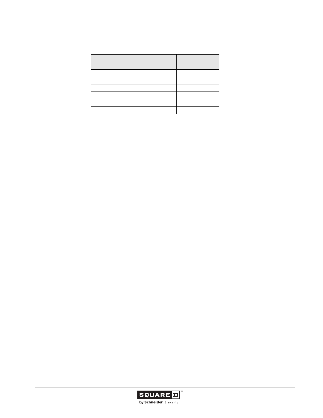
Table 3: Circuit Breaker Endurance
Frame Size
Amperes
0–100 6,000 4,000
101–225 4,000 4,000
226–600 1,000 5,000
601–800 500 3,000
801–2500 500 2,000
2501–4000 400 1,100
— Calibration Retest
Both the 200% and 135% thermal calibration tests are repeated.
Full Load
Operations
No Load
Operations
• Short Circuit
For circuit breakers rated 240 Vac and higher, two short circuit tests per pole and one test with all
poles connected in series is performed. For example, a three-pole circuit breaker receives seven
short circuit tests.
For circuit breakers rated 120/240 Vac, three tests are made with all poles connected in series.
The circuit breaker is connected to the test circuit using wire correctly sized for the rating of the
circuit breakers. The line leads are not more than four feet in length and the load leads are not
more than 10 inches in length.
Note: Successful testing requires that the current be interrupted while monitoring the integrity of
the line-end load connection.
• Trip Out
The 200% thermal calibration test is repeated following the short circuit tests:
— Dielectric
The circuit breaker must withstand, for one minute, twice its rated voltage plus 1000 Vac:
— between line and load terminals with the circuit breaker open, that is, with the circuit breaker in
the tripped and off positions,
— between terminals of opposite polarity with the circuit breaker closed, and
— between live parts and the overall enclosure with the circuit breaker both open and closed.
No conditioning of the circuit breaker can take place during or between these tests. There also can
be no failure of functional parts at the conclusion of the sequences.
• High Available Fault Current Tests
After qualifying a set of circuit breakers to the standard tests, a manufacturer can have additional
circuit breaker samples tested on higher than standard available fault currents.
The following performance requirements apply:
— 200% Thermal Calibration
Each pole of the circuit breaker must trip within a specified time limit when carrying 200% of its
continuous current rating.
— Short Circuit
With the load side terminals connected by 10-inch lengths of specified cable, the circuit breaker is
exposed to a short circuit current for a set time interval. After safe interruption, the circuit breaker is
reset and closed again on the short circuit.
— 250% Thermal Calibration
Each pole of the circuit breaker must trip within a specified time limit when carrying 250% of its
continuous current rating.
14
11/2015 © 1991–2015 Schneider Electric
All Rights Reserved
Page 15
Legacy Thermal-Magnetic / Magnetic Only Molded Case Circuit Breakers
— Dielectric Withstand
The circuit breaker is subjected to twice its rated voltage, but not less than 900 Vac.
When the sample circuit breaker passes these tests, circuit breakers of the same construction can
be marked or labeled with the higher current interrupting rating.
• Switching Duty
The switching duty (SWD) listing applies only to 15 A and 20 A circuit breakers rated at 277 Vac or
less. The circuit breakers are subjected to specified temperature rise tests at predetermined periods
during the endurance operations.
• Performance Requirements for Magnetic Trip Only Circuit Breakers
Design performance verification is tested as follows:
1. Verification of calibration
2. Overload
3. Temperature rise
4. Mechanical and electrical endurance
5. Limited fault current
6. Re-verification of calibration
7. Dielectric
Ratings for Molded Case Circuit Breakers
Molded case circuit breakers are selected by their ratings. The ratings must meet or exceed the
parameters of the electrical system on which they are used.
• Voltage Rating
A circuit breaker may be rated either for alternating current (ac) or direct current (dc) system
applications. The established voltage rating of a circuit breaker is based on design parameters such as
clearance of current carrying parts and dielectric withstand tests both through air and over surfaces.
Voltage ratings indicate the maximum voltage for the electrical system on which the circuit breaker can
be applied. UL Standard 489 recognizes the following ratings:
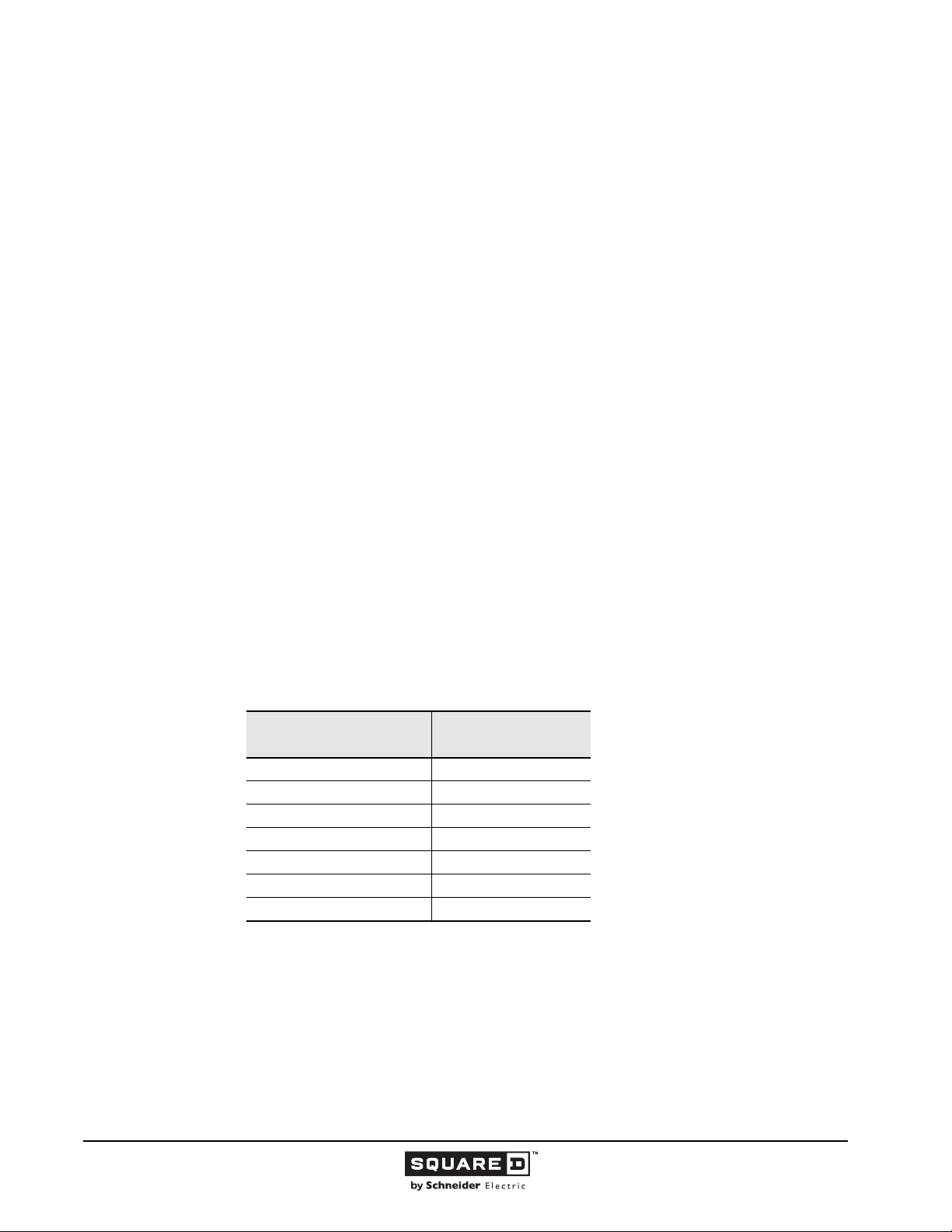
Table 4: UL Standard 489 Recognized Voltage Ratings
Volts for Alternating
Current (ac)
120 125
120/240 125/250
240 250
277 600
480Y/277
480 —
600 —
A circuit breaker can be rated for either ac or dc system applications or both. Circuit breaker voltage
ratings must be equal to or greater than the nominal voltage of the electrical system on which they are
used.
Paragraph 240.85 of the 2002 NEC states that a circuit breaker must be applied in the following
manner:
240.85—A circuit breaker with a straight voltage rating, such as 240 V or 480 V, shall be
permitted to be applied in a circuit in which the nominal voltage between any two conductors
does not exceed the circuit breaker’s voltage rating. A two-pole circuit breaker shall not be used
for protecting a three-phase, corner-grounded delta circuit unless the circuit breaker is marked
1Ø–3Ø to indicate such suitability.
Volts for Direct
Current (dc)
—
© 1991–2015 Schneider Electric
All Rights Reserved
11/2015
15
Page 16

Legacy Thermal-Magnetic / Magnetic Only Molded Case Circuit Breakers
A circuit breaker with a slash rating, such as 120/240 V or 480Y/277 V, shall be permitted to be
applied in a solidly grounded circuit where the nominal voltage of any conductor to ground does
not exceed the lower of the two values of the circuit breaker’s voltage rating and the nominal
voltage between any two conductors does not exceed the higher value of the circuit breaker’s
voltage rating.
FPN: Proper application of molded case circuit breakers on 3-phrase systems, other than
solidly grounded WYE, particularly on corner grounded delta systems, considers the circuit
breakers’ individual pole-interrupting capability.
• Continuous Current Rating
The continuous current rating (or handle rating) of a circuit breaker is defined by NEMA as: “The
maximum direct current or rms current, in amperes, at rated frequency which a device or assembly will
carry continuously without exceeding the specified limits of observable temperature rise.” Continuous
current amperage ratings established by the 2002 NEC, paragraph 240.6 are: 15, 20, 25, 30, 35, 40,
45, 50, 60, 70, 80, 90, 100, 110, 125, 150, 175, 200, 225, 250, 300, 350, 400, 450, 500, 600, 700, 800,
1000, 1200, 1600, 2000, 2500, 3000, 4000, 5000, and 6000 A.
Paragraph 210.20 (A) and 215.3 of the 2002 NEC states:
210.20 (A)—Where a branch circuit supplies continuous loads or any combination of
continuous and noncontinuous loads, the rating of the overcurrent device shall not be less than
the noncontinuous load plus 125 percent of the continuous load.
Exception: Where the assembly, including the overcurrent devices protecting the branch
circuit(s), is listed for operation at 100 percent of its rating, the ampere rating of the overcurrent
device shall be permitted to be not less than the sum of the continuous load plus the
noncontinuous load.
215.3—Feeders shall be protected against overcurrent in accordance with the provisions of
Part I of Article 240. Where a feeder supplies continuous loads or any combination of
continuous and noncontinuous loads, the rating of the overcurrent device shall not be less than
the noncontinuous load plus 125 percent of the continuous load.
Exception No. 1: Where the assembly, including the overcurrent devices protecting the
feeder(s), is listed for operation at 100 percent of its rating, the ampere rating of the overcurrent
device shall be permitted to not less than the sum of the continuous load plus the
noncontinuous load.
Exception No. 2: Overcurrent protection for feeders over 600 volts, nominal, shall comply with
Prt IX of Article 240.
NEC defines a continuous load as: “A load where the maximum current is expected to continue for
three hours or more.”
UL Standard 489 states that circuit breakers must carry 100% of their continuous current rating
indefinitely (without tripping) at 104 °F (40 °C) in free air. Thermal-magnetic circuit breakers are sized
per the NEC for 80% continuous current ratings in the intended enclosure. The continuous current
rating is indicated on the front of each circuit breaker.
• Interrupting Ratings
Schneider Electric thermal-magnetic molded case circuit breakers can be standard interrupting, high
interrupting, extra high interrupting, and time current limiting in construction and are UL listed for the
interrupting ratings as shown below.
UL recognizes component combinations (circuit breaker / circuit breaker and fuse / circuit breaker) for
series connected interrupting ratings. All series rated combinations are marked on the end use
equipment along with the statement, “Caution—Series Rated System.”
For 100% rated applications, see Class 602, 611, 612, and 613 catalogs for more information.
16
11/2015 © 1991–2015 Schneider Electric
All Rights Reserved
Page 17
Legacy Thermal-Magnetic / Magnetic Only Molded Case Circuit Breakers
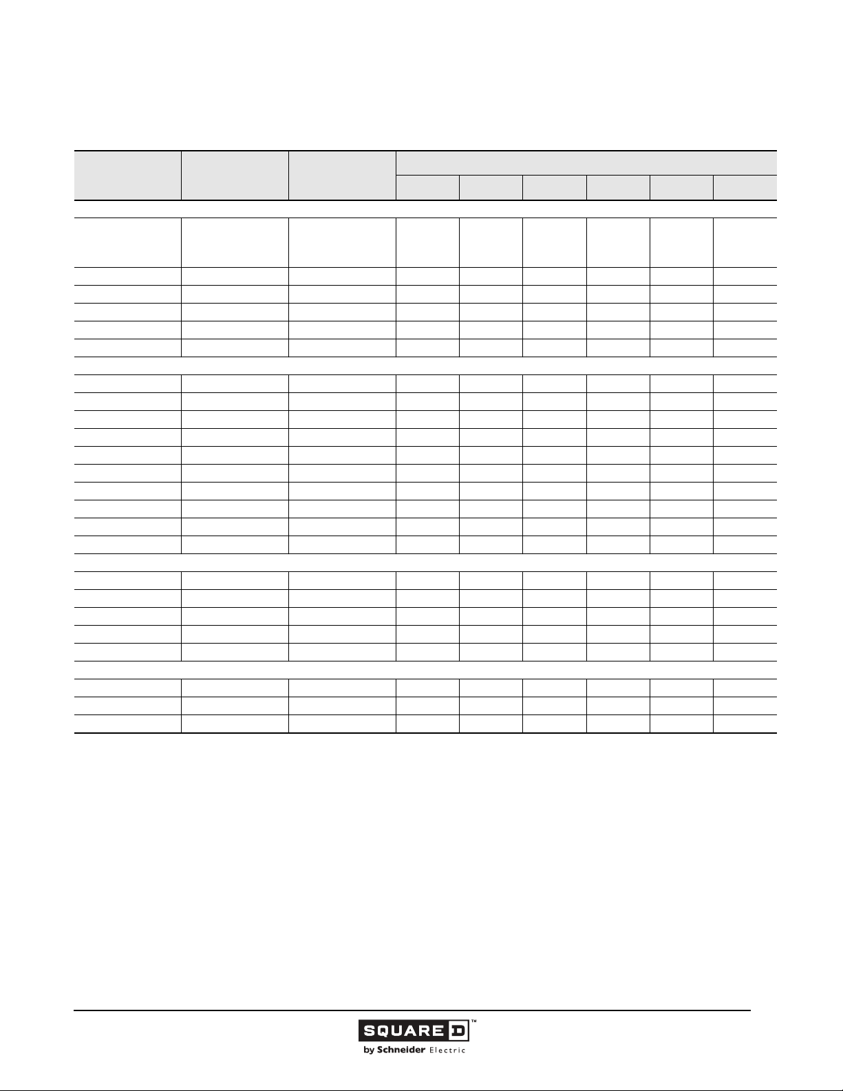
Table 5: UL Listed Interrupting Ratings in kA (RMS Symmetrical Amperes)
Ampacity Catalog Prefix Maximum Voltage
UL Listed Interrupting ratings (in kA)
240 Vac 480 Vac 600 Vac 125 Vdc 250 Vdc 500 Vdc
Standard Interrupting
600 Vac
15–100 FA
70–250 KA 600 Vac 42 25 22 10 10 —
125–600 LA 600 Vac 42 30 22 10 10 —
300–1000 MA 600 Vac 42 30 22 10 10 —
600–1200 NA 600 Vac 100 50 25 — — —
600–2000 PA 600 Vac 65 50 42 — — —
High Interrupting
15–100 FH 600 Vac 65 25 18 50 50 —
70–250 KH 600 Vac 65 35 25 50 50 —
125–400 LH 600 Vac 65 35 25 50 50 —
300–1000 MH 600 Vac 65 65 25 50 50 —
600–2000 PH 600 Vac 125 100 65 — — —
15–100 FH-DC 500 Vdc — ————20
70–250 KH-DC 500 Vdc — ————20
125–400 LH-DC 500 Vdc — ————20
300–1000 MH-DC 500 Vdc — ————20
600–2500 PA-DC 500 Vdc — ————25
Extra High Interrupting
15–100 FC 480 Vac 100 65 ————
110–250 KC 480 Vac 100 65 ————
300–600 LC 600 Vac 100 65 35 — — —
600–1200 NC 600 Vac 125 100 65 — — —
1600–2500 PC 600 Vac 125 100 65 — — —
Current Limiting
20–100 FI 600 Vac 200 200 100 — — —
110–250 KI 600 Vac 200 200 100 — — —
300–600 LI 600 Vac 200 200 100 — — —
Note: These ratings apply to I-Line circuit breakers and circuit breakers with or without lugs.
480 Vac
240 Vac
25
25
10
18
18
—
14
—
—
10
10
5
10
10
5
—
—
—
© 1991–2015 Schneider Electric
All Rights Reserved
11/2015
17
Page 18
Legacy Thermal-Magnetic / Magnetic Only Molded Case Circuit Breakers
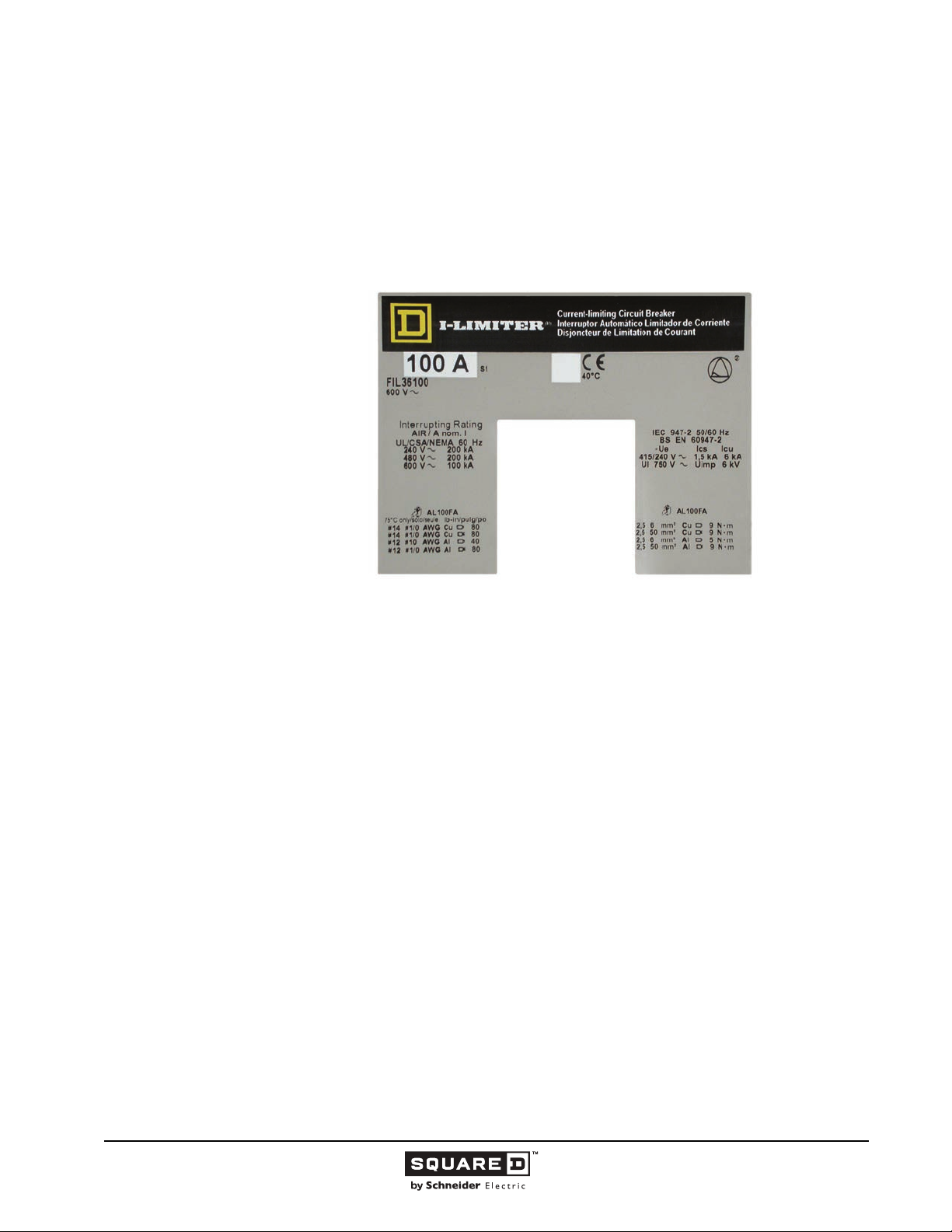
The ampere interrupting rating (AIR) of a circuit breaker is the highest current at rated voltage that the
circuit breaker is intended to interrupt under standard test conditions. The interrupting rating is shown
on the faceplate of the circuit breaker for each voltage level that the circuit breaker can use. Circuit
breakers are selected with interrupting ratings equal to or greater than the available short circuit
current at the point where the circuit breaker is applied in the system. Circuit breaker interrupting
ratings are commonly expressed in rms symmetrical amperes. The industry standardization on rms
symmetrical ampere ratings takes into account asymmetrical current conditions by specifying a power
factor in the test circuit.
Figure 7: Circuit Breaker Faceplate Label
• Ambient Temperature Rating
To meet the requirements of UL Standard 489, CSA, and IEC, molded case circuit breakers are
designed, built and calibrated for use on 50/60 Hertz (Hz) ac systems in a 104 °F (40 °C) ambient
temperature.
The ambient temperature is the temperature of the air surrounding a circuit breaker. Thermal-magnetic
circuit breakers are temperature sensitive devices, and their rated continuous current carrying capacity
is based on a UL specified 104 °F (40 °C) calibration temperature. The ambient temperature can affect
the thermal (overload) tripping characteristics of thermal-magnetic circuit breakers. When applying the
circuit breaker at a temperature other than 104 °F (40 °C) , it may be necessary to rerate the circuit
breaker to compensate for ambient conditions. Conductors are sized using the ampacity rerating
factors shown in NEC Table 310-16 when designating systems for ambient temperatures other than
104 °F (40 °C).
Thermal-magnetic circuit breakers use bimetal strips that bend in response to temperature changes.
Current flowing through the circuit breaker creates most of the heat that causes the tripping action. The
ambient temperature surrounding the circuit breaker either adds to or subtracts from this available
heat.
• Re-rating of Thermal-Magnetic Circuit Breakers for Ambient Conditions
Schneider Electric thermal-magnetic circuit breakers are to be applied in ambient temperatures within
a range of 14 to 104 °F (-10 °C to 60 °C). These re-rating guidelines should be followed:
1. At ambient temperatures between 77—104 °F (25—40 °C), no rerating is necessary.
2. At ambient temperatures between 14—75 °F (-10—24 °C), thermal-magnetic circuit breakers carry
more than their continuous current rating without tripping. Wire and equipment damage can result if
they are not in the same low ambient environment as the circuit breaker.
If closer protection of the equipment and wire is required, the increased current carrying capacity of
the circuit breaker at the lower ambient temperature should be taken into consideration.
3. At ambient temperatures between 106—140 °F (41—60 °C) thermal-magnetic circuit breakers
carry less than their continuous current rating and must be carefully selected to prevent nuisance
tripping.
18
11/2015 © 1991–2015 Schneider Electric
All Rights Reserved
Page 19
Legacy Thermal-Magnetic / Magnetic Only Molded Case Circuit Breakers
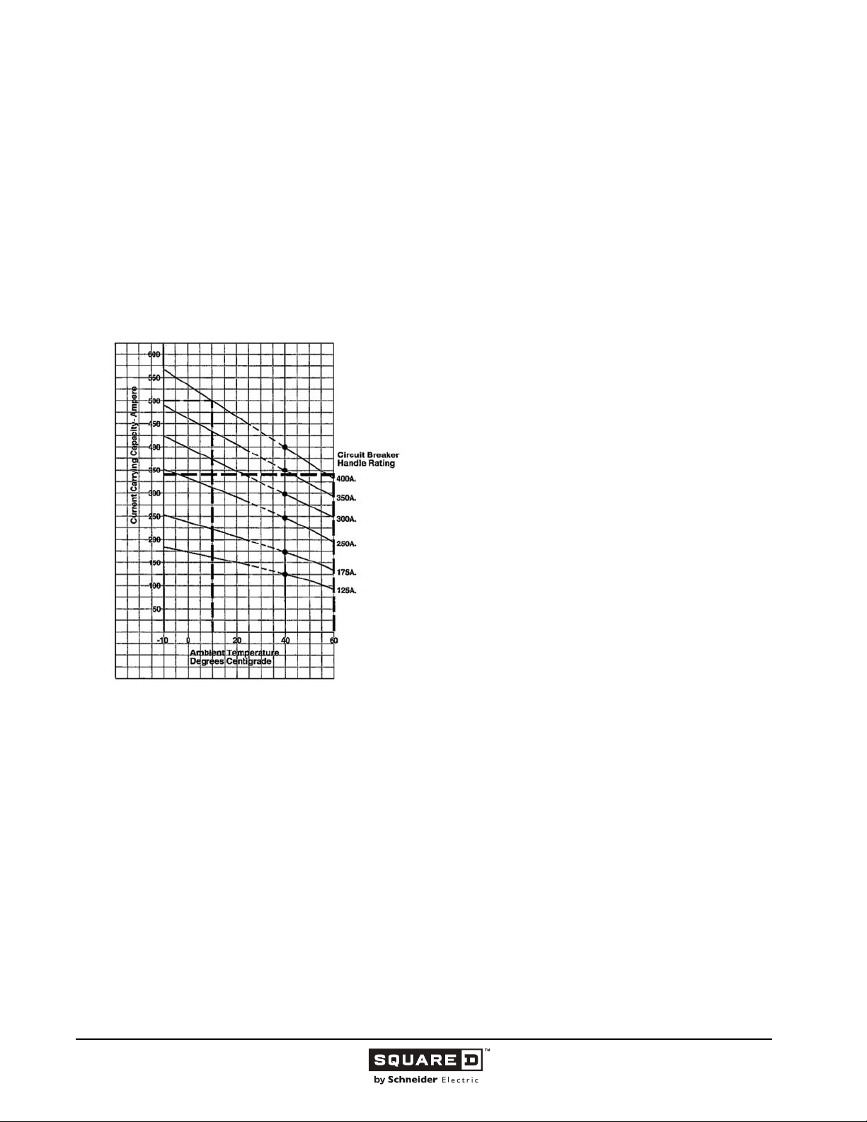
The following procedure is used to determine the continuous current carrying capacity of a thermalmagnetic circuit breaker at ambient temperature other than 104 °F (40 °C) (see data bulletin
Determining Current Carrying Capacity in Special Applications for more information):
1. Refer to the ambient rerating curves for the circuit breaker type.
2. Select the curve for the specific amperage rating of the circuit breaker involved. Note in the figure,
below, that the curve crosses the 104 °F (40 °C) ambient temperature line at the circuit breaker’s
UL listed continuous current rating (handle rating).
3. Follow this curve to the ambient temperature in which the circuit breaker is to be installed.
4. Read the continuous current carrying capacity at this left axis point.
5. Apply any other applicable factors, such as 80% loading per the NEC.
Figure 8: LA Circuit Breaker Ambient Rerating Curves
For example, this figure shows the ambient rerating curves for the
LA thermal-magnetic circuit breaker. Determine the continuous
current carrying capacity of a 400 A LA circuit breaker applied at
104 °F (40 °C) by finding 40 on the horizontal axis and reading up
to the 400 A curve. The circuit breaker carries 400 A, which is its
rated capacity. If the circuit breaker is used on a continuous load (3
hours or more). Paragraph 220-10b of the NEC requires that
loading not exceed 80% of the rating
(400 A x 80 = 320 A).
• Frequency Rating
The standard rated frequency for circuit breakers is 60 Hz, but Schneider Electric circuit breakers can
be applied on 50 Hz systems without thermal or magnetic re-rating. Other frequencies can affect the
thermal, magnetic and short circuit tripping characteristics of circuit breakers.
Applying thermal-magnetic circuit breakers at frequencies above 50/60 Hz requires special
consideration of the effects of high frequency on circuit breaker tripping characteristics. Thermal and
magnetic operations must be treated separately.
• Thermal Tripping Performance
At frequencies below 60 Hz, the thermal rerating of thermal-magnetic circuit breakers is negligible.
However, at frequencies above 60 Hz, thermal rerating is required. High frequency operation causes
abnormal heat rise in the current carrying parts because of the skin effect. One of the most common
frequency applications is at 400 Hz.
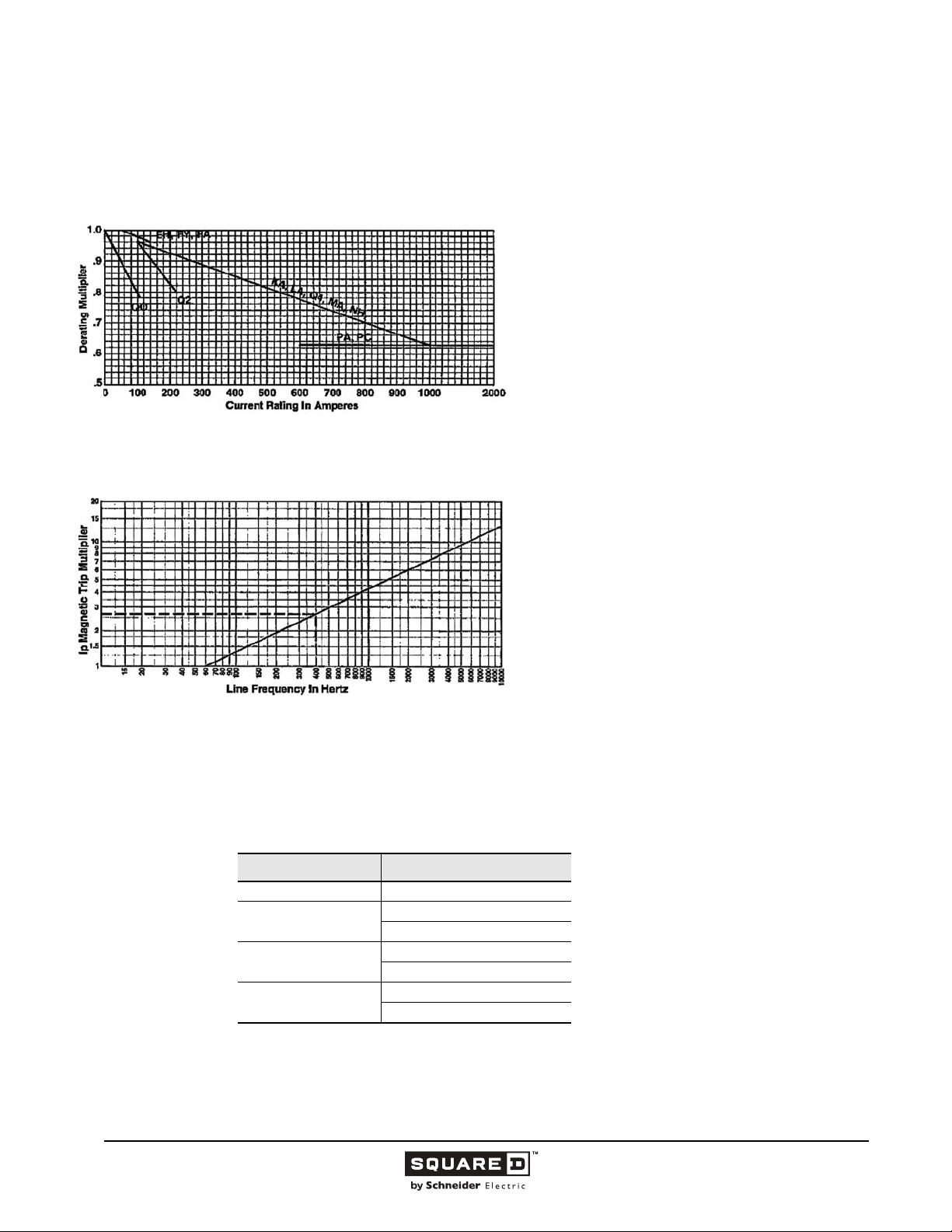
For example, when applying a 200 A kA circuit breaker on a 400 Hz system, the circuit breaker’s
current carrying capacity is as follows:
• Non-continuous loads (less than three hours): The kA circuit breaker may be applied at 0.92 of its
• Continuous loads (3 hours or more): Paragraph 220-10b of the NEC requires that circuit breaker’s
© 1991–2015 Schneider Electric
All Rights Reserved
rating, or 184 A.
loading does not exceed 80% of its rating when used for continuous loads.
19
11/2015
Page 20
Legacy Thermal-Magnetic / Magnetic Only Molded Case Circuit Breakers
(Unless the circuit breaker is rated for operation at 100% of its rating). Therefore, the current carrying
capacity of a 200 A kA circuit breaker operating under continuous load at 400 Hz would be
200 x 0.92 x 0.80 = 147 A.
Figure 9: 400 Hz Thermal Rerating Multiplier
At frequencies above 60 Hz, the interrupting capacity of
thermal-magnetic circuit breakers is less than the 60 Hz
interrupting capacity. Unless specifically marked on
400 Hz systems, the interrupting capacity of Schneider
Electric circuit breakers is reduced to 1/10th of the 60 Hz
interrupting capacity.
• Magnetic Tripping Performance
Figure 10: 60 Hz Current Multipliers
At frequencies above 60 Hz, more current is necessary to
magnetically trip a circuit breaker than at 60 Hz. The figure
below shows the multipliers of 60 Hz current that it takes to
magnetically trip a circuit breaker when applied at various
frequencies. For example, at 60 Hz it takes 1000 A to
magnetically trip a 200 A KA circuit breaker at its low
setting. At 400 Hz it takes 2600 A (2.6 multiplier) to
magnetically trip the same circuit breaker.
• Rerating for Direct Current
Trip curves provide complete time-current characteristics of circuit breakers when applied on ac systems
only. Thermal-magnetic circuit breakers (1000 A frame or less) on dc systems retain their thermal tripping
characteristics, but a multiplier must be applied to the ac magnetic trip level to determine an equivalent dc
trip level.
Below is a list of multipliers for the dc magnetic trip level of each type of thermal-magnetic circuit breaker:
Table 6: Rerating Multipliers for Direct Current
Circuit Breaker Magnetic Trip Level Multiplier
FA/FH/FC 1.15
KA/KH/KC
LA/LH
MA/MH
For example, the equivalent dc magnetic trip levels for a 200 A kA circuit breaker would be:
1. ac Hi Setting = 2000 A + 20%.
2. dc Hi Setting = 2000 A x 1.15 = 2300 A + 20%.
3. ac Lo Setting = 1000 A + 25%.
4. dc Lo Setting = 1000 A x 1.3 = 1300 A + 25%.
20
11/2015 © 1991–2015 Schneider Electric
Hi Setting 1.15
Lo Setting 1.3
Hi Setting 1.2
Lo Setting 1.3
Hi Setting 1.1
Lo Setting 1.2
All Rights Reserved
Page 21

Legacy Thermal-Magnetic / Magnetic Only Molded Case Circuit Breakers
UL Listed 500 Vdc Rated Circuit Breakers
Schneider Electric has UL listed dc thermal-magnetic circuit breakers specifically designed for use on
ungrounded dc systems having a maximum short circuit (loaded) voltage of 500 Vdc or a maximum
floating (unloaded) voltage of 600 Vdc.
This UL listed dc rating is available on FH. KH, LH, MH and PA molded case circuit breakers. Specific
time current characteristic tripping curves are available for these applications.
Return and Exchange Policy
Molded case circuit breakers are factory sealed and no internal inspection or maintenance is required under
normal conditions. Important: DO NOT OPEN THE SEALED CASE. Opening of the sealed case voids the
UL label and the Schneider Electric warranty.
All damaged or used circuit breakers should be replaced as a unit and returned to the factory for inspection.
Upon receipt of the circuit breaker, Schneider Electric performs a thorough inspection of the circuit breaker
and issues a test report (on request). Unused circuit breakers and circuit breakers returned for inspection
must be returned as instructed by the local Schneider Electric Customer Care Center.
Circuit breakers sent to the factory for inspection or testing are not returned. Schneider Electric offers a new
circuit breaker and allows a credit for the circuit breaker that was returned. Price and credit allowances for
all replacements of molded case circuit breakers and trip units are determined by Class, as follows.
• Class I
New circuit breakers that have been broken by handling or assembling, by other than Schneider Electric, or
in transit and have not been in service.
— Allowance
A replacement circuit breaker is furnished and billed at list price minus the regular discount. When the
circuit breaker in need of repair is returned, a credit allowance (42% of the billing price minus any
transportation paid by Schneider Electric) is issued against the invoice of the replacing order.
• Class II
New circuit breakers that meet factory inspection standards and are interchangeable electrically and
physically with standard units of current manufacture.
• Class III
Inoperative circuit breakers.
• Class IV
Exchange of permanent trip circuit breakers (KA, LA, MA or NA) furnished in lieu of circuit breakers
specified with interchangeable trip. These circuit breakers can be identified by a label stating they are
subject to this exchange policy.
© 1991–2015 Schneider Electric
All Rights Reserved
— Allowance
A replacement circuit breaker is furnished at the list price minus the regular discount. When the unused
circuit breaker is returned, a credit (in the amount of the billing price minus 20% restocking charge and
any transportation paid by Schneider Electric) is issued.
— Allowance
A replacement circuit breaker is furnished at the list price minus the regular discount. Upon return of the
circuit breaker claimed inoperative, full credit is issued on the basis of the replacement cost plus any
transportation costs paid by the customer.
Examination by Customer Care must substantiate the claimed inoperative nature of the material
returned.
— Allowance
A replacement circuit breaker within the same frame size, but of a different trip rating than that
exchanged, is furnished at the lowest recognized competitive list price for a trip unit of the same frame
size and trip rating minus the regular discount. This exchange arrangement requires that the replaced
circuit breaker be returned to Schneider Electric.
21
11/2015
Page 22
Legacy Thermal-Magnetic / Magnetic Only Molded Case Circuit Breakers
Catalog Numbers
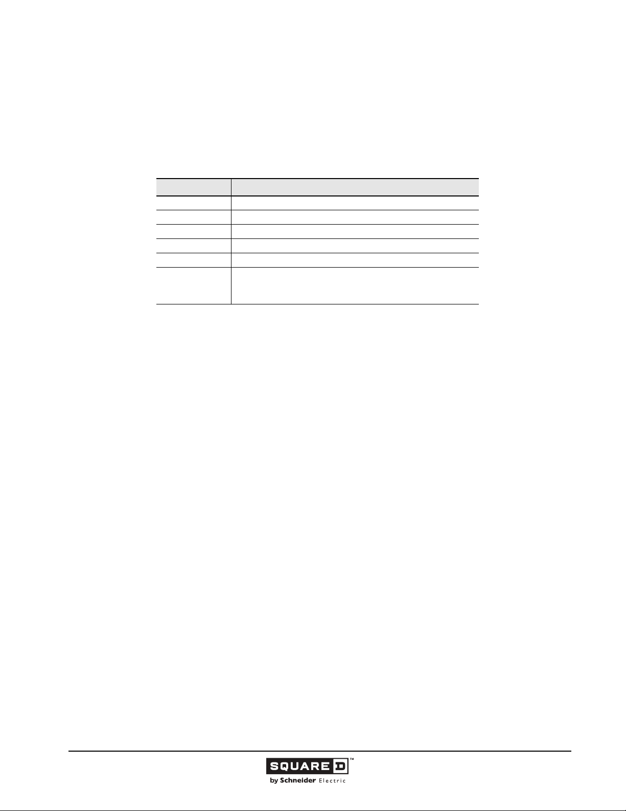
Square D brand circuit breakers by Schneider Electric are ordered by a catalog number that includes
the breaker family, description, poles, voltage rating, amperage rating and suffix.
The table below shows a typical catalog number broken down by components. For example,
FAL36050V2100, can be broken down as follows:
Table 7: Catalog Numbers
Components Description
FA 100 A frame circuit breaker
L Circuit breaker with lugs on both ends
3 Number of poles
6 Voltage rating
050 Continuous current amperage rating (handle rating)
V and 2100 V indicates the Visi-Blade feature and the 2100 indicates a
factory installed contact alarm. These two components are
the suffix
22
11/2015 © 1991–2015 Schneider Electric
All Rights Reserved
Page 23
Legacy Thermal-Magnetic / Magnetic Only Molded Case Circuit Breakers
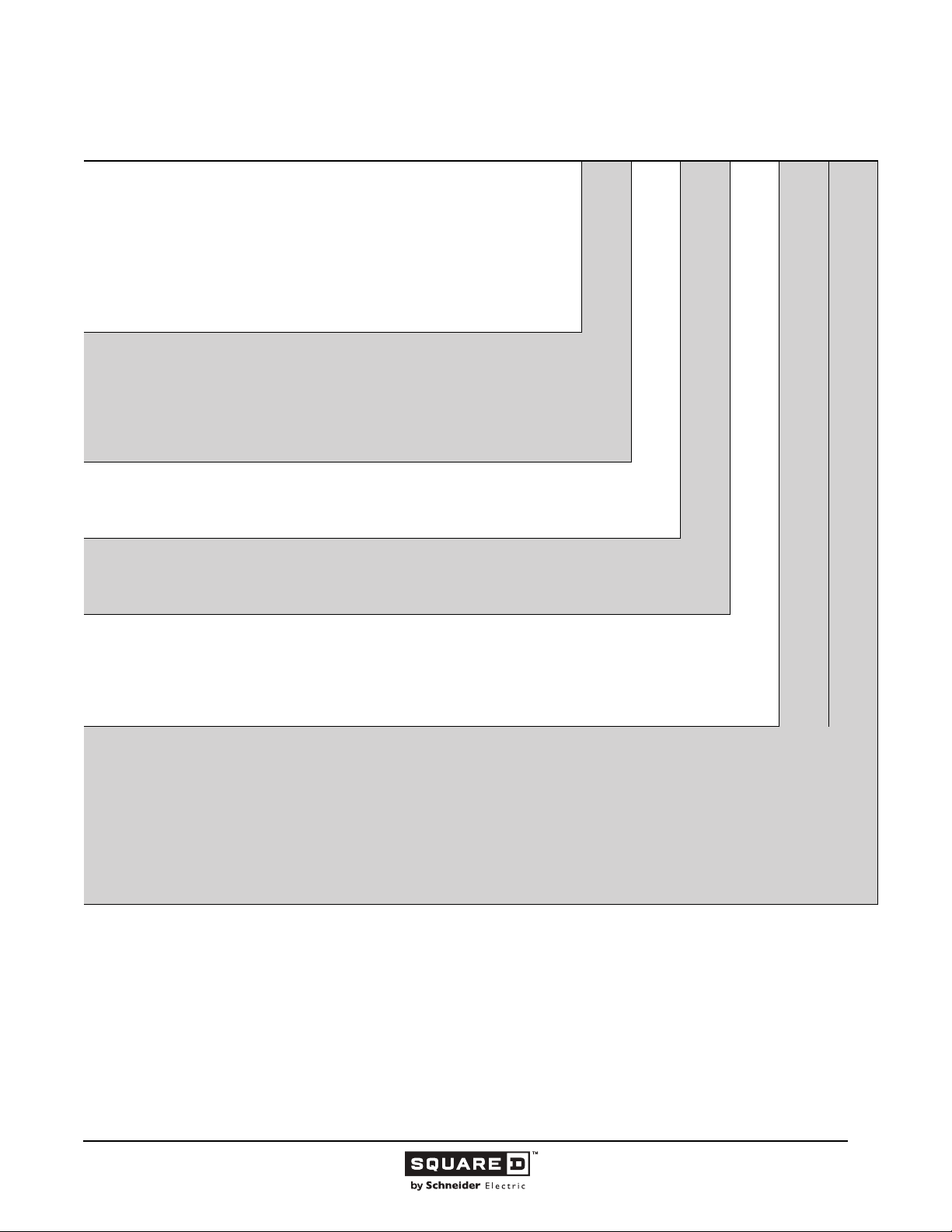
Table 8: Breakdown of Typical Catalog Number
Circuit Breaker
Family
FY - 30 A Frame
FA - 100 A Frame
KA - 250 A Frame
LA - 400 A Frame
MA 1000 A Frame
NA - 1200 A Frame
Description
NO LETTER - (I-Line) Plug-on Circuit Breaker
B - (I-Line) Bolt-on Circuit Breaker (400 A frame maximum)
F - Terminal Pads Only (No Lugs)
L - Lugs on Both Ends (Merchandised - Universal Circuit Breaker)
P - Lugs OFF End Only
R - Plug-on Circuit Breaker (I-Line Type DO with Plug-on Line and Load connectors)
Poles
1 - One-Pole
2 - Two-pole
3 - Three-Pole
Voltage Rating
2 - 240 Vac
4 - 480 Vac
6 - 600 Vac
Ampere Rating
015–090 - 15–90 A Rating
100–900 - 100–900 A Rating
1000–1200 - 1000–1200 A Rating
000 or 0000 - Molded Case Switch
000X or 000XX - Molded Case Switch
Suffix
The suffix indicates a special feature of the circuit breaker.
A, B, C - indicated I-Line Phase Connections
CV - Indicates Visi-Blade
M - Indicates Automatic Molded Case Switch
XXM - Indicated Instantaneous Trip Only (Mag-Gard) (i.e., 18M is 300-1100 A
adjustable trip range)
XXT - Indicates adjustable magnetic trip with responsive thermal (mining circuit breakers)
G - Indicates Ground Fault Shunt Trip accessory
XXXX - I.e., 2100 Indicates a factory installed accessory
Note:
“A” is replaced by letter “H” for High Interrupting
“A” is replaced by letter “C” for Extra High Interrupting
“A” is replaced by letter “I” for Current Limiting. (FA, KA. LA
circuit breakers only)
FA L36 050 V 2100
© 1991–2015 Schneider Electric
All Rights Reserved
11/2015
23
Page 24
Legacy Thermal-Magnetic / Magnetic Only Molded Case Circuit Breakers
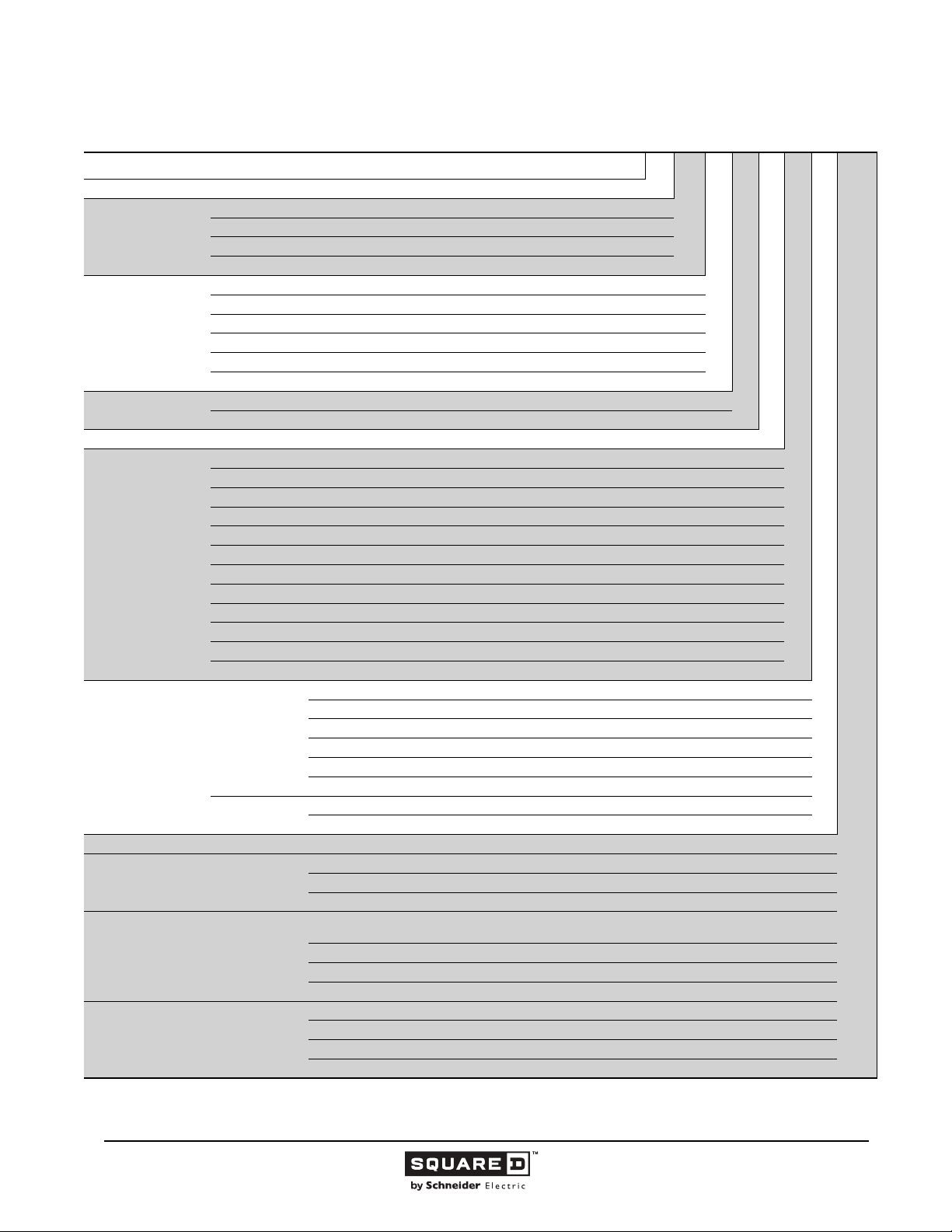
Table 9: PowerPact Q-frame Catalog Numbering System
1
Number Segment Character Description Q BL32250 4 2L W
Circuit Breaker Family Q
B 10 kA
Circuit Breaker Type
(Interrupting Rating)
Connection Type
Poles
240 Volts Only 2
Continuous Current
Rating (Amperes)
I-Line Phasing
Special Ambient C A = 50 C
Control Taps L
Termination Options T
Special Features Y
1
See Class 611, 612, 613, and 734 catalogs for other PowerPact and Masterpact circuit breakers.
2
May be collapsed if none.
3
May be collapsed if none. May be multiple options.
D 25 kA
G 65 kA
J 100 kA
A I-Line
E Bolt-on I-Line
F No lugs (Bus Connection)
L Lugs on both ends
M Lugs on ON (I) end only
P Lugs on OFF (O) end only
2 Two-pole
3 Three-pole
70
80
90
100
110
125
150
175
200
225
250
000 S 22 = Switch (QB only)
1 = AB
2 = AC
Two-pole
Three-pole
3 = BA
4 = BC
5 = CA
6 = CB
None = ABC
6 = CBA
U = Control taps applied to ON (I) end
V = Control taps applied to OFF (O) end
W = Control taps applied to both ends
M = Lugs applied to OFF (O) end; studs with nuts and washers
threaded onto ON (I) end
N = Lugs applied to ON (I) end; studs applied to OFF (O) end (nuts/washers in bag, supplied)
P = Studs applied to ON (I) end; Lugs applied to OFF (O) end (nuts/washers in bag, supplied)
S = Studs on BOTH ends (nuts/ washers in bag, supplied)
D = Calibration test report supplied
F =Fungus treatment
P = Handle Padlock Attachment, ON (I) or OFF (O) position
Q = Handle Padlock Attachment, OFF (O) position only
24
11/2015 © 1991–2015 Schneider Electric
All Rights Reserved
3
Page 25
Legacy Thermal-Magnetic / Magnetic Only Molded Case Circuit Breakers
100 Ampere Frame
This section provides specific information on Schneider Electric 100 A frame thermal-magnetic molded
case circuit breakers. For more information, see the “Introduction” in this catalog.
Description
Table 10: Description of 100 A Frame Circuit Breakers
Circuit Breaker Description
FA/FH
FC
FI
FY 15–30 A, 277 Vac, 50/60 Hz, one-pole
Applications
• FI current limiting circuit breakers are used for electrical systems where high fault currents can occur.
• FA/FH, FC, and FI circuit breakers are used in industrial enclosures, panelboards, switchboards,
busway plug-in units, combination starters, or motor control centers.
• FY thermal-magnetic circuit breakers are used in I-Line panelboards and switchboards.
15–100 A, 600 Vac, 50/60 Hz,
250 Vdc, One-, two- and three-pole
15–100 A, 480 Vac, 50/60 Hz,
two- and three-pole
20–100 A, 600 Vac 50/60 Hz,
two- and three-pole
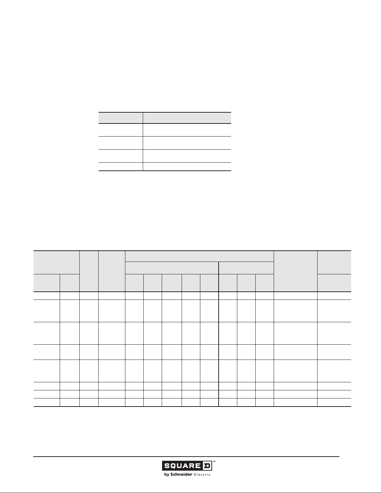
Table 11: 100 A Frame Interrupting Ratings
Catalog Number
Prefix
No. of
Poles
Unit
Mount
FAL 240
Vac
FAL 480
Vac
FAL 600
Vac
FHL
FHL-DC
FCL FC 2, 3 20–100 100 100 65 65 — — — — 22a 10/2.5
FIL FI 2, 3 20–100 200 200 200 200 100 — — — 16a 6/1.5
1
Separate UL rating available for 240 Vac and 480 Vac grounded B single phase systems. Circuit breakers must be ordered with 5861 suffix.
2
UL listed 500 Vdc rating for use on ungrounded systems. Must be connected three-poles in series. Consult the Schneider Electric Customer Care Center for
additional information
Note: For IEC 60947-2 rated S-line ratings, not UL listed, see Supplemental Digest.
I-Line 120 240
FY 1 15–30 18 14 14 — — — — — 11a, 13b 10/2.5
FA 240
Vac
FA 480
Vac
FA 600
Vac
1
1
FH
2, 3
2
— 3 — —— — ————20K — —
Cont.
Ampere
AC Volts - RMS Symmetrical Amperes DC Volts
Rating
1
15–100
2
15–100
3
15–100
1
15–100
2
15–100
3
15–100
2
15–100
3
15–100
1
15–30
1
35–100
15–100
10
10
10
25
25
25
25
25
65
65
65
UL Listed Interrupting Rating (kA)
480Y/
277
—
10
10
18
25
25
25
25
65
25
65
480 600 125 250 500 415/240
—
—
—
18
18
18
18
18
65
25
25
—
—
—
—
—
—
—
—
18
—
18
—
18
14
18
14
—
—
—
—
25
18
Federal Specs.
W-C-375B/GEN
5
—
—
5
5
10
10
10
10
10
10
10
50
5
—
5
—
—
—
10
—
10
—
10
—
10
—
—
—
10
—
50
—
11a
11b, 12b
11b, 12b
11a, 12a, 13a
13b
13b
18a
18a
13a
13a
22a
IEC 60947-2
Icu/Ics (kA)
AC Voltage
10/2.5
10/2.5
10/2.5
10/2.5
© 1991–2015 Schneider Electric
All Rights Reserved
11/2015
25
Page 26
Legacy Thermal-Magnetic / Magnetic Only Molded Case Circuit Breakers
Selection Data
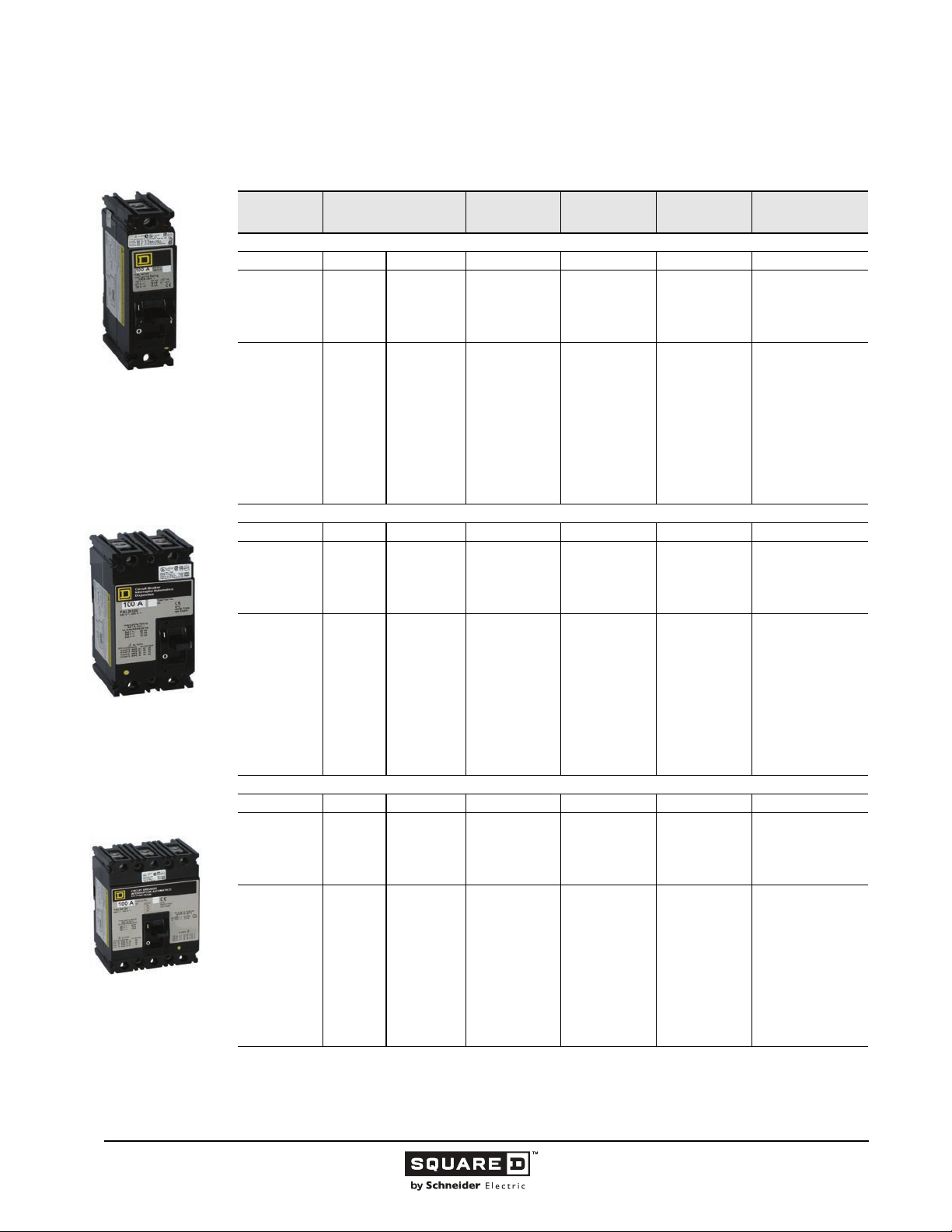
FAL One-pole
15–100 A
FAL/FHL Two-pole
15–100 A
FAL/FHL/FCL Three-pole
15–100 A
Table 12: 100 A Frame Unit Mount Circuit Breakers
Ampere
Rating
FAL Standard Interrupting
15
20
25
30
35
40
45
50
60
70
80
90
100
FAL Standard Interrupting
15
20
25
30
35
40
45
50
60
70
80
90
100
FAL Standard Interrupting
15
20
25
30
35
40
45
50
60
70
80
90
100
1
FCL two-pole circuit breaker built using three-pole module.
AC Magnetic Trip
Settings Amperes
Hold Trip 120 Vac 240 Vac 240 Vac
275
275
275
275
400
400
400
400
830
800
800
900
900
Hold Trip 277 Vac/125 Vdc 480 Vac/250 Vdc 480 Vac/250 Vdc
275
275
275
275
400
400
400
400
800
800
800
900
900
Hold Trip 600 Vac/250 Vdc 600 Vac/250 Vdc
275
275
275
275
400
400
400
400
800
800
800
900
900
600
600
600
600
850
850
850
850
1450
1450
1450
1700
1700
600
600
600
600
850
850
850
850
1450
1450
1450
1700
1700
600
600
600
600
850
850
850
850
1450
1450
1450
1700
1700
One-pole
Catalog No.
FAL12015
FAL12020
FAL12025
FAL12030
FAL12035
FAL12040
FAL12045
FAL12050
FAL12060
FAL12070
FAL12080
FAL12090
FAL12100
FAL14015
FAL14020
FAL14025
FAL14030
FAL14035
FAL14040
FAL14045
FAL14050
FAL14060
FAL14070
FAL14080
FAL14090
FAL14100
—
—
—
—
—
—
—
—
—
—
—
—
—
Two-Pole
Catalog No.
1
FAL22015
FAL22020
FAL22025
FAL22030
FAL22035
FAL22040
FAL22045
FAL22050
FAL22060
FAL22070
FAL22080
FAL22090
FAL22100
FAL24015
FAL24020
FAL24025
FAL24030
FAL24035
FAL24040
FAL24045
FAL24050
FAL24060
FAL24070
FAL24080
FAL24090
FAL24100
FAL26015
FAL26020
FAL26025
FAL26030
FAL26035
FAL26040
FAL26045
FAL26050
FAL26060
FAL26070
FAL26080
FAL26090
FAL26100
Three-Pole
Catalog No.
FAL32015
FAL33020
FAL32025
FAL32030
FAL32035
FAL32040
FAL32045
FAL32050
FAL32060
FAL32070
FAL32080
FAL32090
FAL32100
FAL34015
FAL34020
FAL34025
FAL34030
FAL34035
FAL34040
FAL34045
FAL34050
FAL34060
FAL34070
FAL34080
FAL34090
FAL34100
FAL36015
FAL36020
FAL36025
FAL36030
FAL36035
FAL36040
FAL36045
FAL36050
FAL36060
FAL36070
FAL36080
FAL36090
FAL36100
Standard Lug Kit
Wire Range
AL50FA
#14-#4 Cu or
#12-#4 AI
AL100FA
#14-#1/0 Cu or
#12-#1/o AI
AL50FA
#14-#4 Cu or
#12-#4 AI
AL100FA
#14-#1/0 Cu or
#12-#1/o AI
AL50FA
#14-#4 Cu or
#12-#4 AI
AL100FA
#14-#1/0 Cu or
#12-#1/o AI
—Continued on next page
26
11/2015 © 1991–2015 Schneider Electric
All Rights Reserved
Page 27
Legacy Thermal-Magnetic / Magnetic Only Molded Case Circuit Breakers
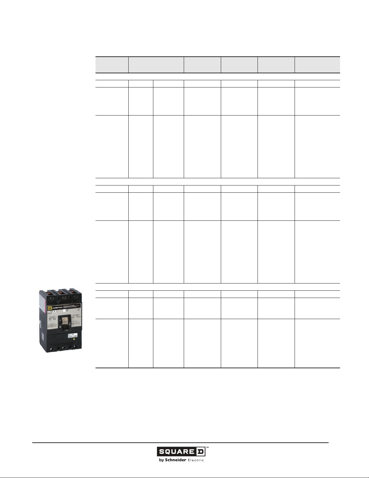
FIL Two- and Three-pole
20–100 A
Table 12: 100 A Frame Unit Mount Circuit Breakers
Ampere
Rating
FHL High Interrupting
15
20
25
30
35
40
45
50
60
70
80
90
100
FCL Extra High Interrupting
15
20
25
30
35
40
45
50
60
70
80
90
100
FIL I-Limiter Current Limiting
20
30
40
50
60
70
80
90
100
1
FCL two-pole circuit breaker built using three-pole module.
2
Rated 277 Vac 15 and 20 A FY circuit breakers are rated for switching duty (SWD). 15, 20, 25, and 30 A FA I-Line circuit breakers
are also available (no SWD rating).
1
2
FCL two-pole circuit breaker built using three-pole module.
AC Magnetic Trip
Settings Amperes
Hold Trip 277 Vac/125 Vdc 600 Vac/250 Vdc 600 Vac/250 Vdc
275
275
275
275
400
400
400
400
800
800
800
900
900
Hold Trip 480 Vac
275
275
275
275
400
400
400
400
800
800
800
900
900
Hold Trip 600 Vac 600 Vac
275
275
400
400
800
800
800
800
800
600
600
600
600
850
850
850
850
1450
1450
1450
1700
1700
600
600
600
600
850
850
850
850
1450
1450
1450
1700
1700
600
600
850
850
1700
1700
1700
1700
1700
One-pole
Catalog No.
FHL16015
FHL16020
FHL16025
FHL16030
FHL16035
FHL16040
FHL16045
FHL16050
FHL16060
FHL16070
FHL16080
FHL16090
FHL16100
—
—
—
—
—
—
—
—
—
—
—
—
—
—
—
—
—
—
—
—
—
—
1
Two-Pole
Catalog No.
FHL26015
FHL26020
FHL26025
FHL26030
FHL26035
FHL26040
FHL26045
FHL26050
FHL26060
FHL26070
FHL26080
FHL26090
FHL26100
2
FCL24015
FCL24020
FCL24025
FCL24030
FCL24035
FCL24040
FCL24045
FCL24050
FCL24060
FCL24070
FCL24080
FCL24090
FCL24100
FIL26020
FIL26030
FIL26040
FIL26050
FIL26060
FIL26070
FIL26080
FIL26090
FIL26100
Three-Pole
Catalog No.
FHL36015
FHL36020
FHL36025
FHL36030
FHL36035
FHL36040
FHL36045
FHL36050
FHL36060
FHL36070
FHL36080
FHL36090
FHL36100
480 Vac
FCL34015
FCL34020
FCL34025
FCL34030
FCL34035
FCL34040
FCL34045
FCL34050
FCL34060
FCL34070
FCL34080
FCL34090
FCL34100
FIL36020
FIL36030
FIL36040
FIL36050
FIL36060
FIL36070
FIL36080
FIL36090
FIL36100
Standard Lug Kit
Wire Range
AL50FA
#14–#4 Cu or
#12–#4 AI
AL100FA
#14–#1/0 Cu or
#12–#1/0 AI
CU30FA
#14–#10 Cu
AL100FA4
#14–#3 Cu or
#12–#1 AI
AL50FA
1-#14–#4 Cu or
1-#12–#4 AI
AL100FA
1-#14–#1/0 Cu or
1-#12–#1/0 AI
—Continued on next page
© 1991–2015 Schneider Electric
All Rights Reserved
11/2015
27
Page 28
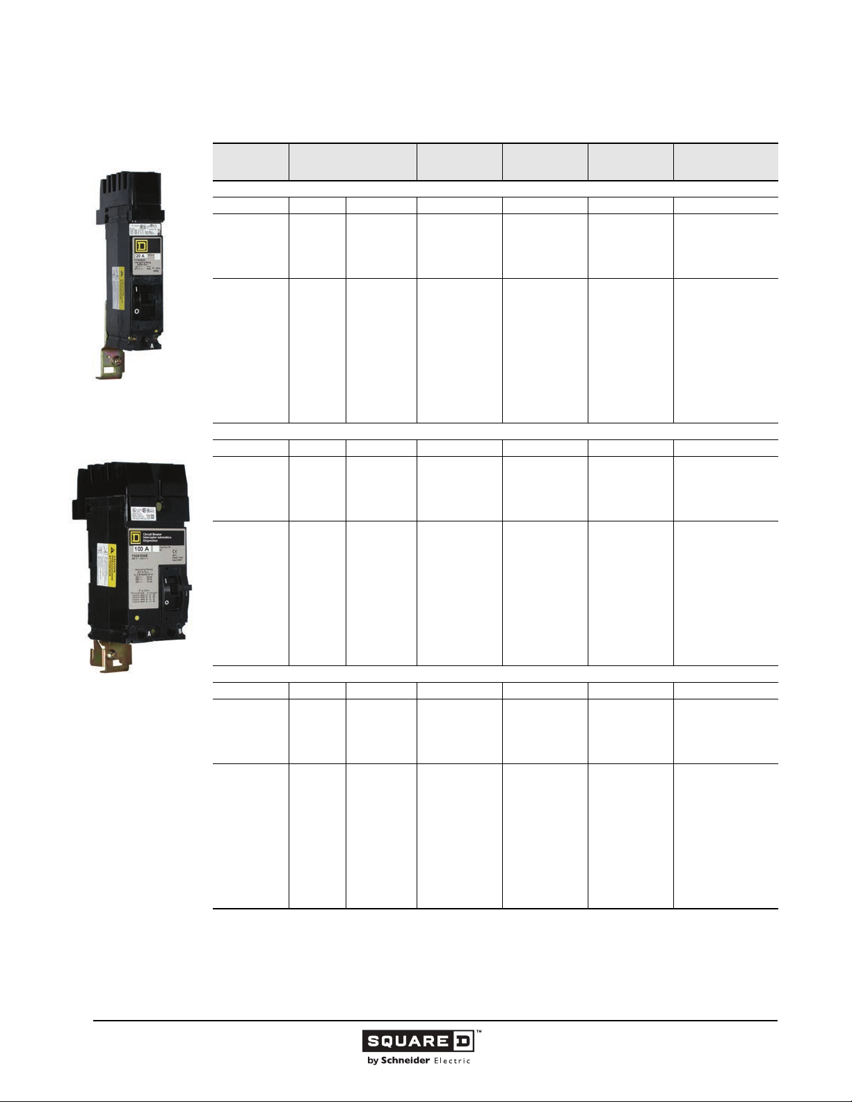
Legacy Thermal-Magnetic / Magnetic Only Molded Case Circuit Breakers
Table 13: 100 A Frame I-Line Circuit Breakers
FY/ FA/FH One-pole
1-1/2 in. Mounting Height
FA/FH Two-pole
3 in. Mounting Height
Ampere
Rating
AC Magnetic Trip
Settings Amperes
One-pole1
Catalog No.
Two-Pole
Catalog No.
1
Three-Pole
Catalog No.
Standard Lug Kit
Wire Range
FA Standard Interrupting
Hold Trip 240 Vac 240 Vac
15
20
25
30
35
40
45
50
60
70
80
90
100
275
275
275
275
400
400
400
400
830
800
800
900
900
600
600
600
600
850
850
850
850
1450
1450
1450
1700
1700
—
—
—
—
—
—
—
—
—
—
—
—
—
FA22015( )
FA22020( )
FA22025( )
FA22030( )
FA22035( )
FA22040( )
FA22045( )
FA22050( )
FA22060( )
FA22070( )
FA22080( )
FA22090( )
FA22100( )
FA32015
FA33020
FA32025
FA32030
FA32035
FA32040
FA32045
FA32050
FA32060
FA32070
FA32080
FA32090
FA32100
AL50FA
1-#14–#4 Cu or
1-#12–#4 AI
AL100FA
1-#14–#1/0 Cu or
1-#12–#1/0 AI
FA Standard Interrupting
Hold Trip 277 Vac/125 Vdc 480 Vac/250 Vdc 480 Vac/250 Vdc
15
20
25
30
35
40
45
50
60
70
80
90
100
275
275
275
275
400
400
400
400
800
800
800
900
900
600
600
600
600
850
850
850
850
1450
1450
1450
1700
1700
FY14015( )
FY14020( )
FY14025( )
FY14030( )
FA14035( )
FA14040( )
FA14045( )
FA14050( )
FA14060( )
FA14070( )
FA14080( )
FA14090( )
FA14100( )
FA24015( )
2
FA24020( )
2
FA24025( )
2
FA24030( )
3
FA24035( )
3
FA24040( )
3
FA24045( )
3
FA24050( )
3
FA24060( )
3
FA24070( )
3
FA24080( )
3
FA24090( )
3
FA24100( )
FA34015
FA34020
FA34025
FA34030
FA34035
FA34040
FA34045
FA34050
FA34060
FA34070
FA34080
FA34090
FA34100
AL50FA
1-#14–#4 Cu or
1-#12–#4 AI
AL100FA
1-#14–#1/0 Cu or
1-#12–#1/0 AI
2
FA Standard Interrupting
Hold Trip 600 Vac/250 Vdc 600 Vac/250 Vdc
15
20
25
30
35
40
45
50
60
70
80
90
100
1
FCL two-pole circuit breaker built using three-pole module.
2
Rated 277 Vac 15 and 20 A FY circuit breakers are rated for switching duty (SWD). 15, 20, 25, and 30 A FA I-Line circuit breakers
are also available (no SWD rating).
3
Rated 277 Vac, 125 Vdc except FY, which has no dc rating. 15–30 A breakers suitable for use with 140 or 167 °F (60 or 75 °C)
conductors. 35-100 A circuit breakers are suitable for use with 167 °F (75 °C) conductors.
275
275
275
275
400
400
400
400
800
800
800
900
900
600
600
600
600
850
850
850
850
1450
1450
1450
1700
1700
—
—
—
—
—
—
—
—
—
—
—
—
—
FA26015( )
FA26020( )
FA26025( )
FA26030( )
FA26035( )
FA26040( )
FA26045( )
FA26050( )
FA26060( )
FA26070( )
FA26080( )
FA26090( )
FA26100( )
FA36015
FA36020
FA36025
FA36030
FA36035
FA36040
FA36045
FA36050
FA36060
FA36070
FA36080
FA36090
FA36100
AL50FA
1-#14–#4 Cu or
1-#12–#4 AI
AL100FA
1-#14–#1/0 Cu or
1-#12–#1/0 AI
—Continued on next page
28
11/2015 © 1991–2015 Schneider Electric
All Rights Reserved
Page 29
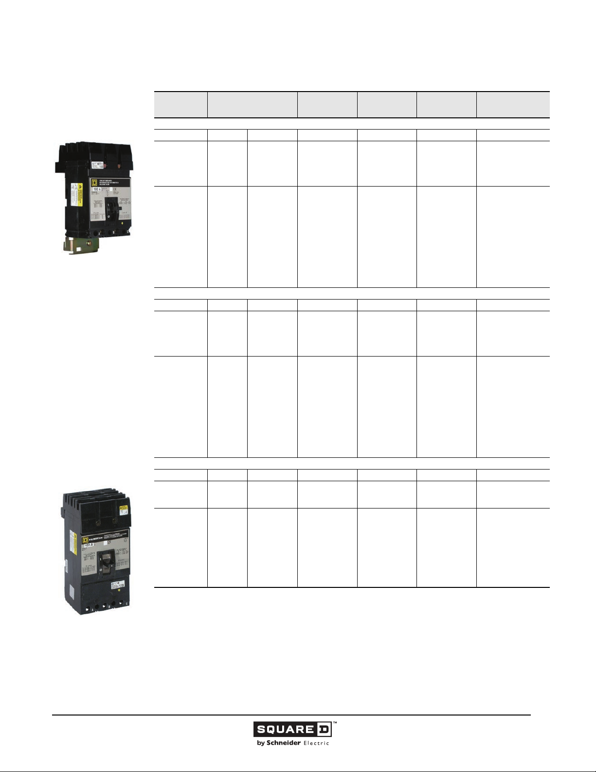
Legacy Thermal-Magnetic / Magnetic Only Molded Case Circuit Breakers
Table 13: 100 A Frame I-Line Circuit Breakers (continued)
FA/FH Three-pole
FC Two- and Three-pole
4-1/2 in. Mounting Height
FI Two- and Three-pole
4-1/2 in. Mounting Height
Ampere
Rating
FH High Interrupting
15
20
25
30
35
40
45
50
60
70
80
90
100
FC Extra High Interrupting
15
20
25
30
35
40
45
50
60
70
80
90
100
FI I-Limiter Current Limiting
20
30
40
50
60
70
80
90
100
1
One and two-pole circuit breaker catalog numbers are completed by adding the required phase connection letters as a suffix to
the catalog number.
2
Rated 277 Vac 15 and 20 A FY circuit breakers are rated for switching duty (SWD). 15, 20, 25, and 30 A FA I-Line circuit breakers
are also available (no SWD rating).
3
Rated 277 Vac, 125 Vdc except FY, which has no dc rating. 15–30 A breakers suitable for use with 140 or 167 °F (60 or 75 °C)
conductors. 35-100 A circuit breakers are suitable for use with 167 °F (75 °C) conductors.
AC Magnetic Trip
Settings Amperes
Hold Trip 277 Vac/125 Vdc 600 Vac/250 Vdc 600 Vac/250 Vdc
275
275
275
275
400
400
400
400
800
800
800
900
900
Hold Trip 480 Vac 480 Vac
275
275
275
275
400
400
400
400
800
800
800
900
900
Hold Trip 600 Vac 600 Vac
275
275
400
400
800
800
800
800
800
600
600
600
600
850
850
850
850
1450
1450
1450
1700
1700
600
600
600
600
850
850
850
850
1450
1450
1450
1700
1700
600
600
850
850
1700
1700
1700
1700
1700
One-pole1
Catalog No.
FH16015( )
FH16020( )
FH16025( )
FH16030( )
FH16035( )
FH16040( )
FH16045( )
FH16050( )
FH16060( )
FH16070( )
FH16080( )
FH16090( )
FH16100( )
—
—
—
—
—
—
—
—
—
—
—
—
—
—
—
—
—
—
—
—
—
—
Two-Pole
Catalog No.
FH26015( )
FH26020( )
FH26025( )
FH26030( )
FH26035( )
FH26040( )
FH26045( )
FH26050( )
FH26060( )
FH26070( )
FH26080( )
FH26090( )
FH26100( )
FC24015( )
FC24020( )
FC24025( )
FC24030( )
FC24035( )
FC24040( )
FC24045( )
FC24050( )
FC24060( )
FC24070( )
FC24080( )
FC24090( )
FC24100( )
FI26020( )
FI26030( )
FI26040( )
FI26050( )
FI26060( )
FI26070( )
FI26080( )
FI26090( )
FI26100( )
1
Three-Pole
Catalog No.
FH36015
FH36020
FH36025
FH36030
FH36035
FH36040
FH36045
FH36050
FH36060
FH36070
FH36080
FH36090
FH36100
FC34015
FC34020
FC34025
FC34030
FC34035
FC34040
FC34045
FC34050
FC34060
FC34070
FC34080
FC34090
FC34100
FI36020
FI36030
FI36040
FI36050
FI36060
FI36070
FI36080
FI36090
FI36100
Standard Lug Kit
Wire Range
AL50FA
1-#14–#4 Cu or
1-#12–#4 AI
AL100FA
1-#14–#1/0 Cu or
1-#12–#1/0 AI
CU30FA4
1-#14–#10 Cu
AL100FA4
1-#14–#3 Cu or
1-#12–#1 AI
AL50FA
1-#14–#4 Cu or
1-#12–#4 AI
AL100FA
1-#14–#1/0 Cu or
1-#12–#1/0 AI
© 1991–2015 Schneider Electric
All Rights Reserved
11/2015
29
Page 30
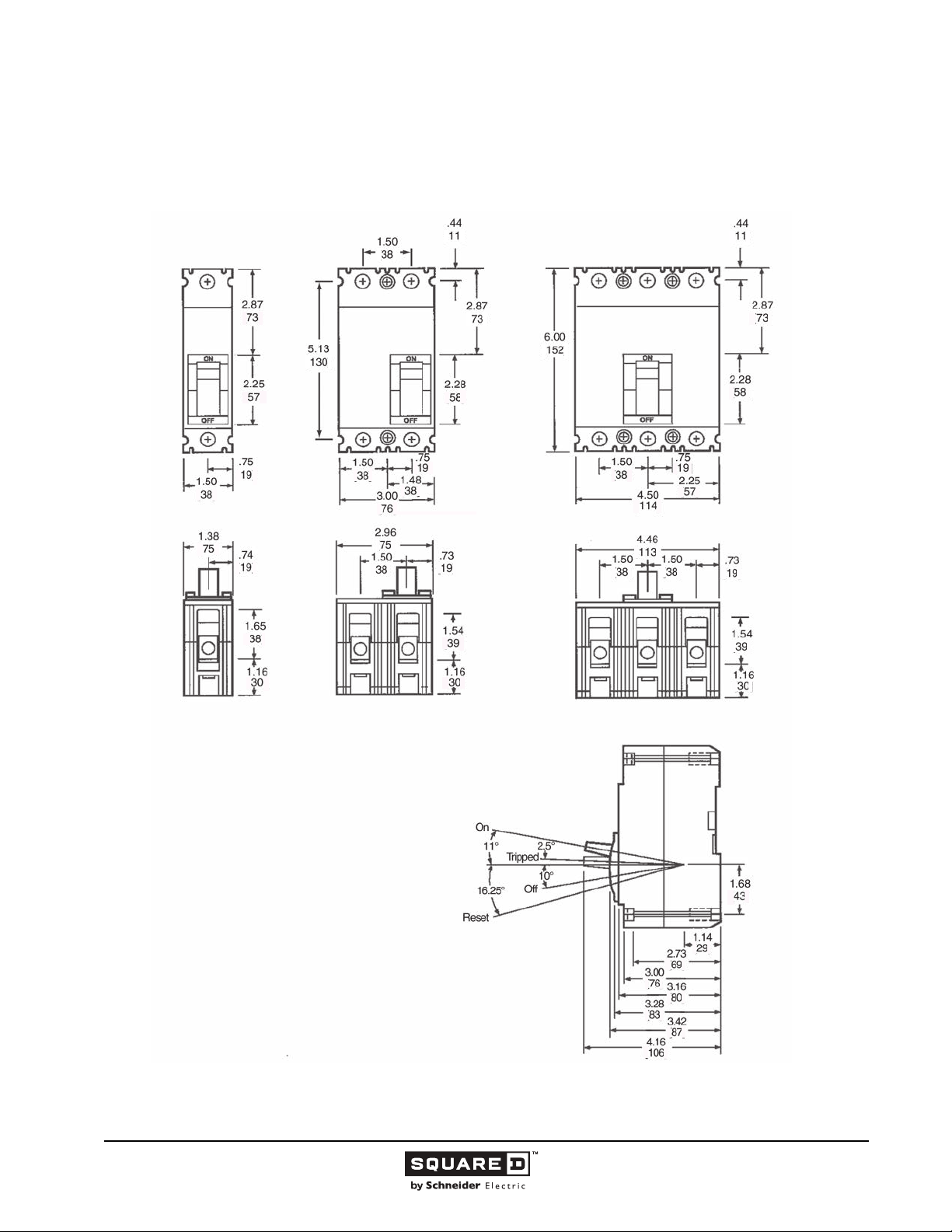
Legacy Thermal-Magnetic / Magnetic Only Molded Case Circuit Breakers
Dimensions
Figure 11: FAL, FHL, FCL 100 A Frame
( )
( )
( )
( )
( )
( )
( )
( )
( )
( )
()
( )
( )
( )
( )
( )
()
()
( )
( )
( )
( )
( )
( )
( )
( )
( )
( )
( )
( )
( )
( )
( )
( )
( )
( )
( )
FCL two-pole circuit breaker dimension is
the same as a three-pole circuit breaker.
( )
( )
( )
( )
( )
( )
( )
( )
Dimensions:
30
11/2015 © 1991–2015 Schneider Electric
All Rights Reserved
in.
(mm)
Page 31
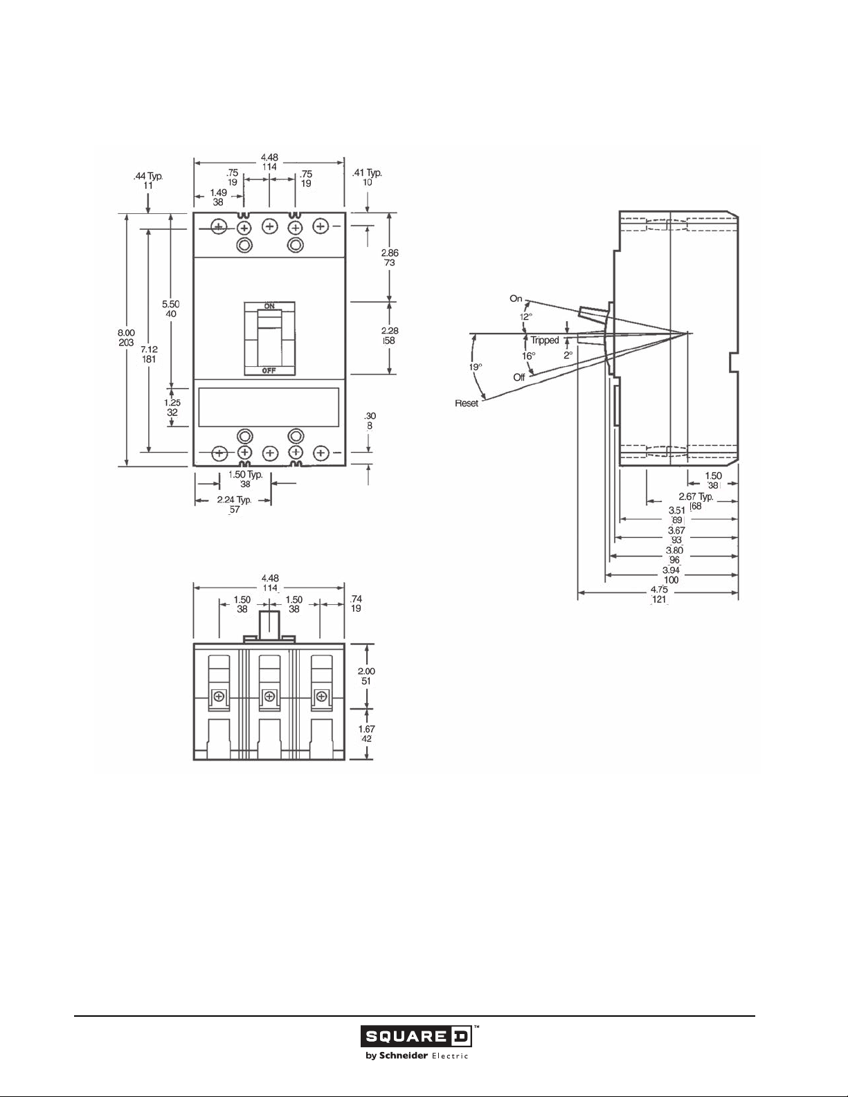
Legacy Thermal-Magnetic / Magnetic Only Molded Case Circuit Breakers
Figure 12: FIL 100 A Frame
( )
( )
( )
( )
( )
( )
( )
( )
( )
( )
( )
( )
( )
( )
( )
( )
( )
( )
( )
( )
( )
( )
( )
( )
( )
( )
( )
( )
Dimensions:
in.
(mm)
© 1991–2015 Schneider Electric
All Rights Reserved
11/2015
31
Page 32
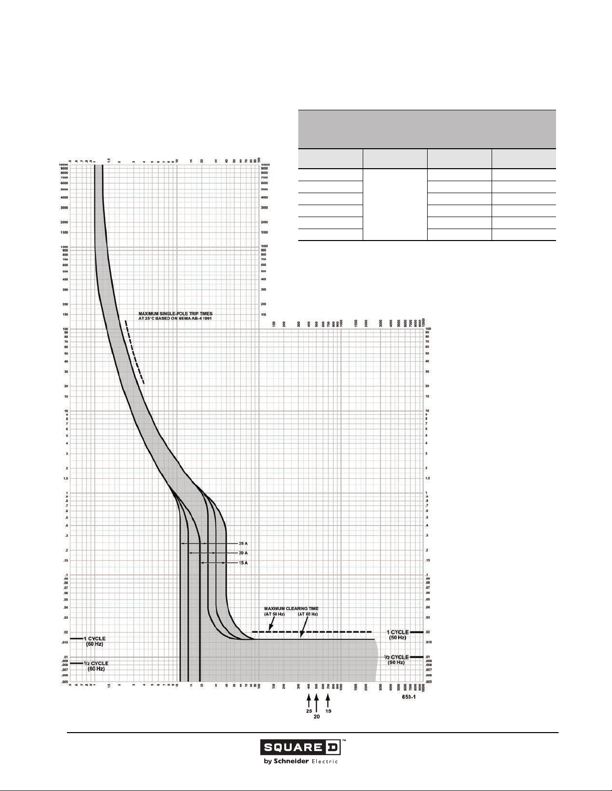
Legacy Thermal-Magnetic / Magnetic Only Molded Case Circuit Breakers
Tripping Curves
FA/FH/FC FAMILY MOLDED CASE CIRCUIT BREAKERS
CHARACTERISTIC TRIP CURVE NO. 650-1
MULTIPLES OF RATED CURRENT
Circuit Breaker
Prefix
FA
FA 480 1
FC 240 2, 3
FC 480 2, 3
FA 600 2, 3
FA, FH 600 1
1
120 Vac maximum.
2
277 Vac maximum.
This curve is to be used for application and coordination purposes only.
The EZ-AMP
coordination studies.
All time/current characteristic curve data is based on 104 °F (40 °C) ambient cold
start. Terminations are made with conductors of appropriate length and ratings.
CIRCUIT BREAKER INFORMATION
Continuous
Ampere Rating
15–25
TM
overlay feature at the bottom of the page should be used during
Maximum AC
Voltage
240 1
Number of Poles
1
, 2, 3
2
, 2, 3
2
, 2, 3
TIME IN SECONDS
TIME IN SECONDS
Tripping curves for
coordination studies are
available upon request.
Curve No. 0650TC0001
December 2000
Drawing No. B48095-650-01
(Replaces 0650TC9001)
MULTIPLES OF RATED CURRENT
32
11/2015 © 1991–2015 Schneider Electric
All Rights Reserved
Page 33
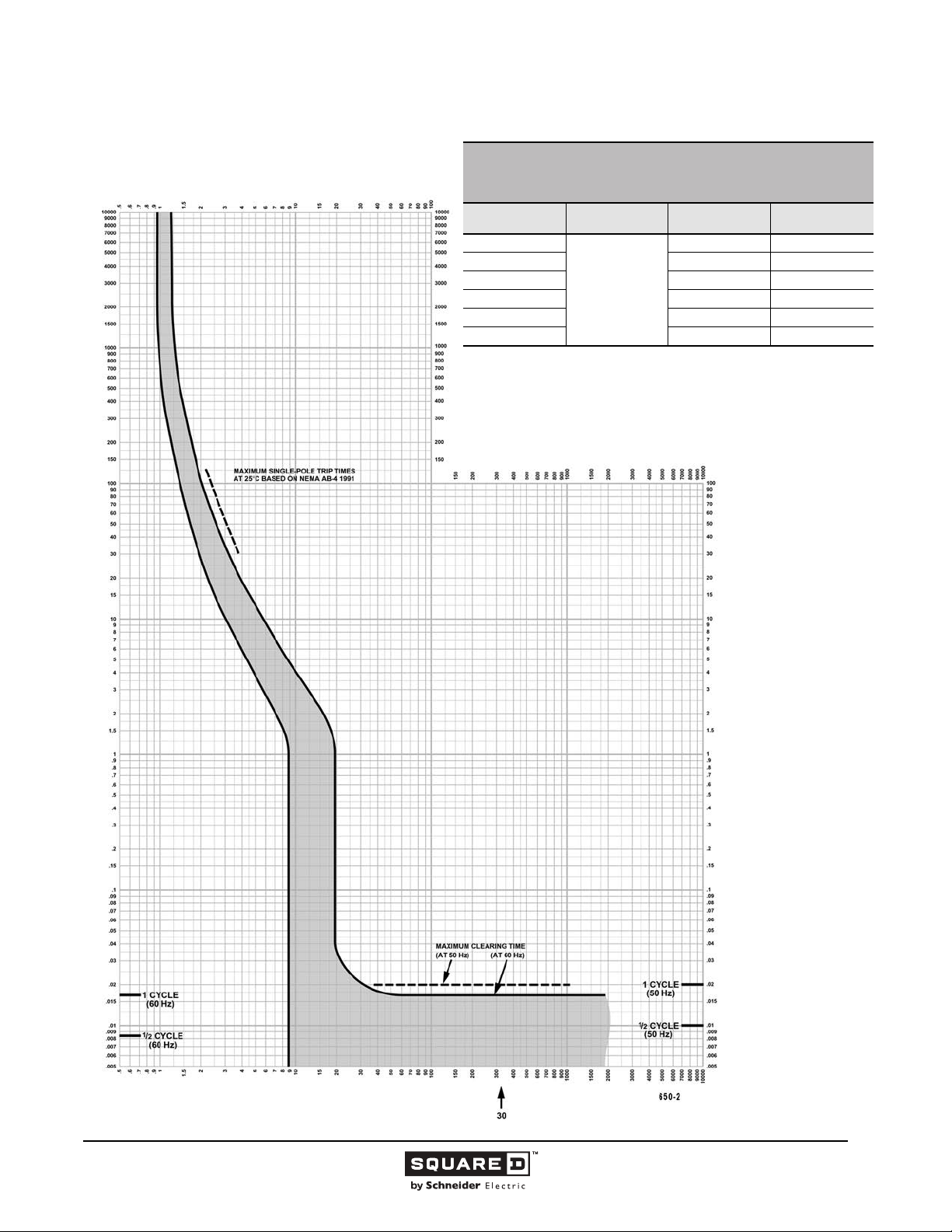
Legacy Thermal-Magnetic / Magnetic Only Molded Case Circuit Breakers
FA/FH/FC FAMILY MOLDED CASE CIRCUIT BREAKERS
MULTIPLES OF RATED CURRENT
Circuit Breaker
1
120 Vac maximum.
2
277 Vac maximum.
This curve is to be used for application and coordination purposes only.
The EZ-AMP overlay feature at the bottom of the page should be used during
coordination studies.
All time/current characteristic curve data is based on 104 °F (40 °C) ambient cold
start. Terminations are made with conductors of appropriate length and ratings.
CHARACTERISTIC TRIP CURVE NO. 650-2
CIRCUIT BREAKER INFORMATION
Prefix
FA
FA 480 1
FC 240 2, 3
FC 480 2, 3
FA 600 2, 3
FH 600 1
Continuous
Ampere Rating
30
Maximum AC
Voltage
240 1
Number of Poles
1
, 2, 3
2
, 2, 3
2
, 2, 3
TIME IN SECONDS
TIME IN SECONDS
Tripping curves for
coordination studies are
available upon request.
Curve No. 0650TC0002
December 2000
Drawing No. B48095-650-02
(Replaces 0650TC9002)
MULTIPLES OF RATED CURRENT
© 1991–2015 Schneider Electric
All Rights Reserved
11/2015
33
Page 34
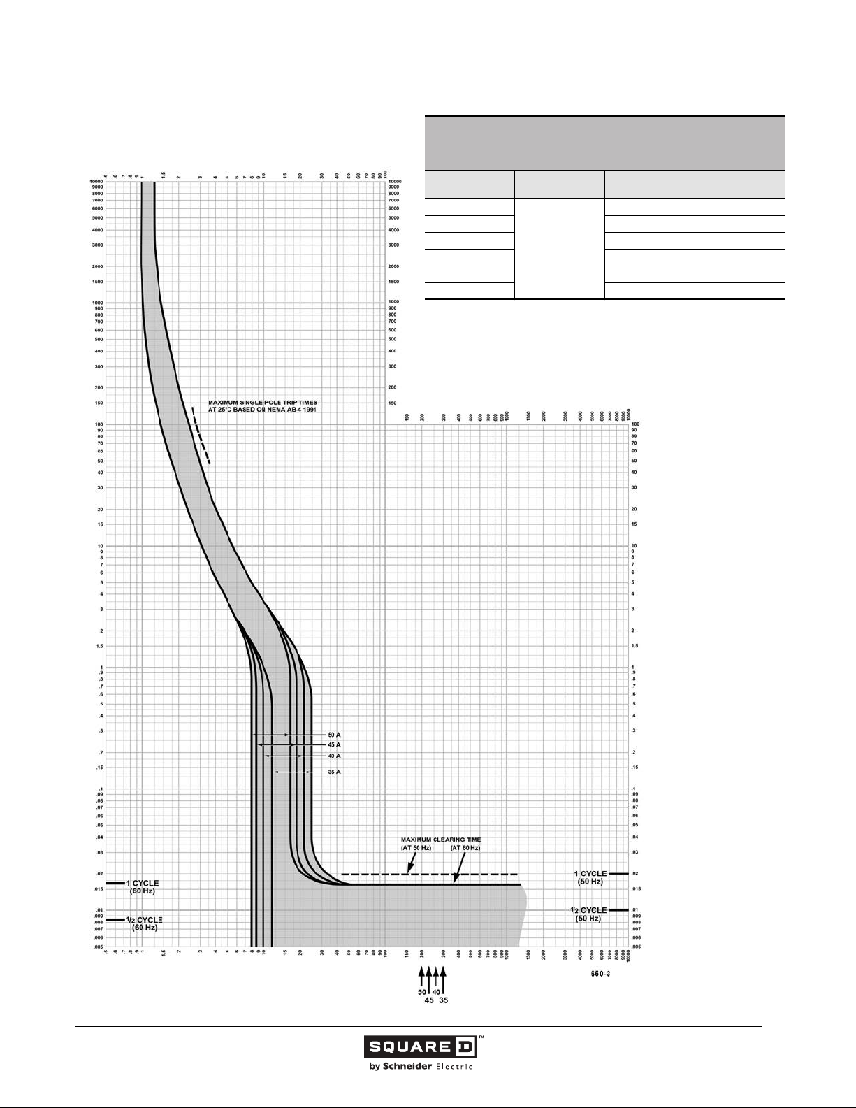
Legacy Thermal-Magnetic / Magnetic Only Molded Case Circuit Breakers
FA/FH/FC FAMILY MOLDED CASE CIRCUIT BREAKERS
CHARACTERISTIC TRIP CURVE NO. 650-3
MULTIPLES OF RATED CURRENT
Circuit Breaker
Prefix
FA
FA 480 1
FC 240 2, 3
FC 480 2, 3
FA 600 2, 3
FH 600 1
1
120 Vac maximum.
2
277 Vac maximum.
This curve is to be used for application and coordination purposes only.
The EZ-AMP overlay feature at the bottom of the page should be used during
coordination studies.
All time/current characteristic curve data is based on 104 °F (40 °C) ambient cold
start. Terminations are made with conductors of appropriate length and ratings.
CIRCUIT BREAKER INFORMATION
Continuous
Ampere Rating
35–60
Maximum AC
Voltage
240 1
Number of Poles
1
, 2, 3
2
, 2, 3
2
, 2, 3
TIME IN SECONDS
TIME IN SECONDS
Tripping curves for
coordination studies are
available upon request.
Curve No. 0650TC0003
December 2000
Drawing No. B48095-650-03
(Replaces 650-3,
dated April, 1990)
MULTIPLES OF RATED CURRENT
© 1991–2015 Schneider Electric
All Rights Reserved
11/2015
34
Page 35
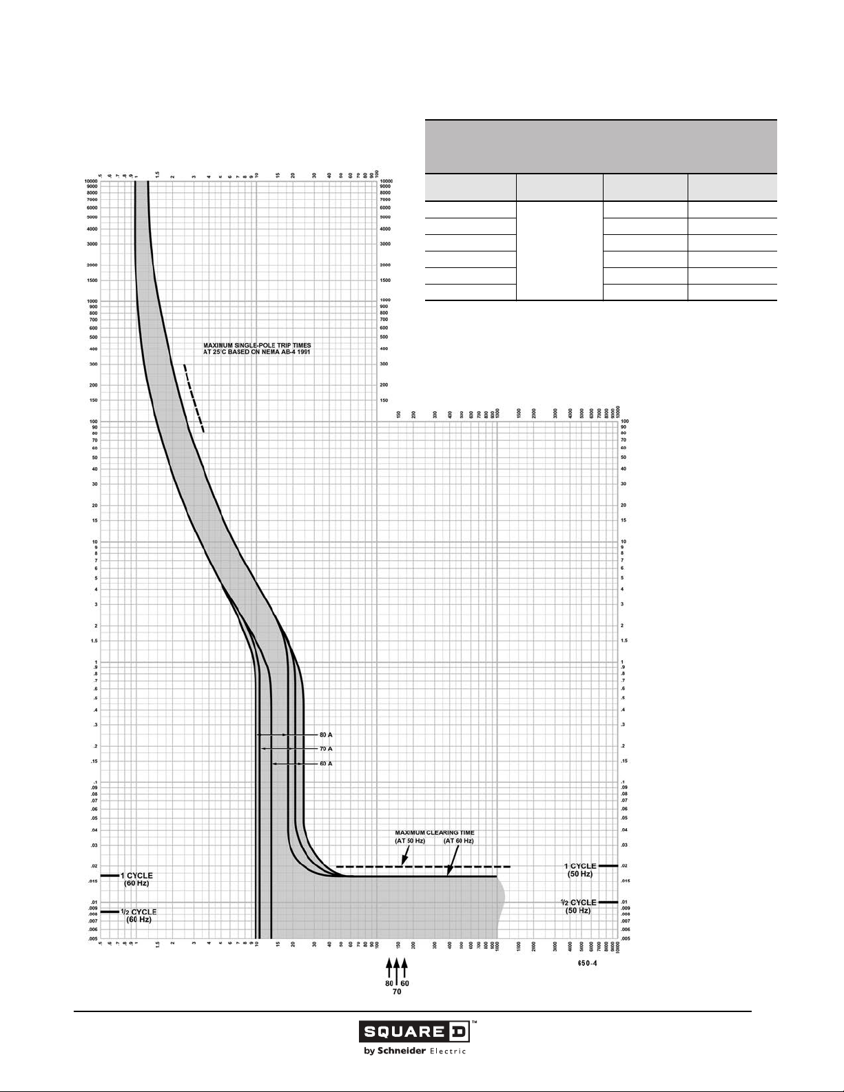
Legacy Thermal-Magnetic / Magnetic Only Molded Case Circuit Breakers
FA/FH/FC FAMILY MOLDED CASE CIRCUIT BREAKERS
MULTIPLES OF RATED CURRENT
Circuit Breaker
1
120 Vac maximum.
2
277 Vac maximum.
This curve is to be used for application and coordination purposes only.
The EZ-AMP overlay feature at the bottom of the page should be used during
coordination studies.
All time/current characteristic curve data is based on 104 °F (40 °C) ambient cold
start. Terminations are made with conductors of appropriate length and ratings.
CHARACTERISTIC TRIP CURVE NO. 650-4
CIRCUIT BREAKER INFORMATION
Prefix
FA
FA 480 1
FC 240 2, 3
FC 480 2, 3
FA 600 2, 3
FH 600 1
Continuous
Ampere Rating
60–80
Maximum AC
Voltage
240 1
Number of Poles
1
, 2, 3
2
, 2, 3
2
, 2, 3
TIME IN SECONDS
TIME IN SECONDS
Tripping curves for
coordination studies are
available upon request.
Curve No. 0650TC0004
December 2000
Drawing No. B48095-650-04
(Replaces 0650TC9004)
MULTIPLES OF RATED CURRENT
© 1991–2015 Schneider Electric
All Rights Reserved
11/2015
35
Page 36
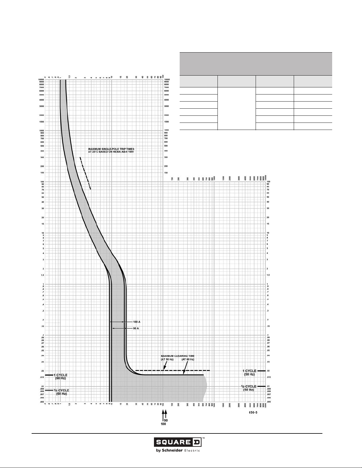
Legacy Thermal-Magnetic / Magnetic Only Molded Case Circuit Breakers
FA/FH/FC FAMILY MOLDED CASE CIRCUIT BREAKERS
CHARACTERISTIC TRIP CURVE NO. 650-5
MULTIPLES OF RATED CURRENT
Circuit Breaker
Prefix
FA
FA 480 1
FC 240 2, 3
FC 480 2, 3
FA 600 2, 3
FH 600 1
1
120 Vac maximum.
2
277 Vac maximum.
This curve is to be used for application and coordination purposes only.
The EZ-AMP overlay feature at the bottom of the page should be used during
coordination studies.
All time/current characteristic curve data is based on 104 °F (40 °C) ambient cold
start. Terminations are made with conductors of appropriate length and ratings.
CIRCUIT BREAKER INFORMATION
Continuous
Ampere Rating
90 & 100
Maximum AC
Voltage
240 1
Number of Poles
1
, 2, 3
2
, 2, 3
2
, 2, 3
TIME IN SECONDS
TIME IN SECONDS
Tripping curves for
coordination studies are
available upon request.
Curve No. 0650TC0005
December 2000
Drawing No. B48095-650-05
(Replaces 0650TC9005)
MULTIPLES OF RATED CURRENT
© 1991–2015 Schneider Electric
All Rights Reserved
11/2015
36
Page 37
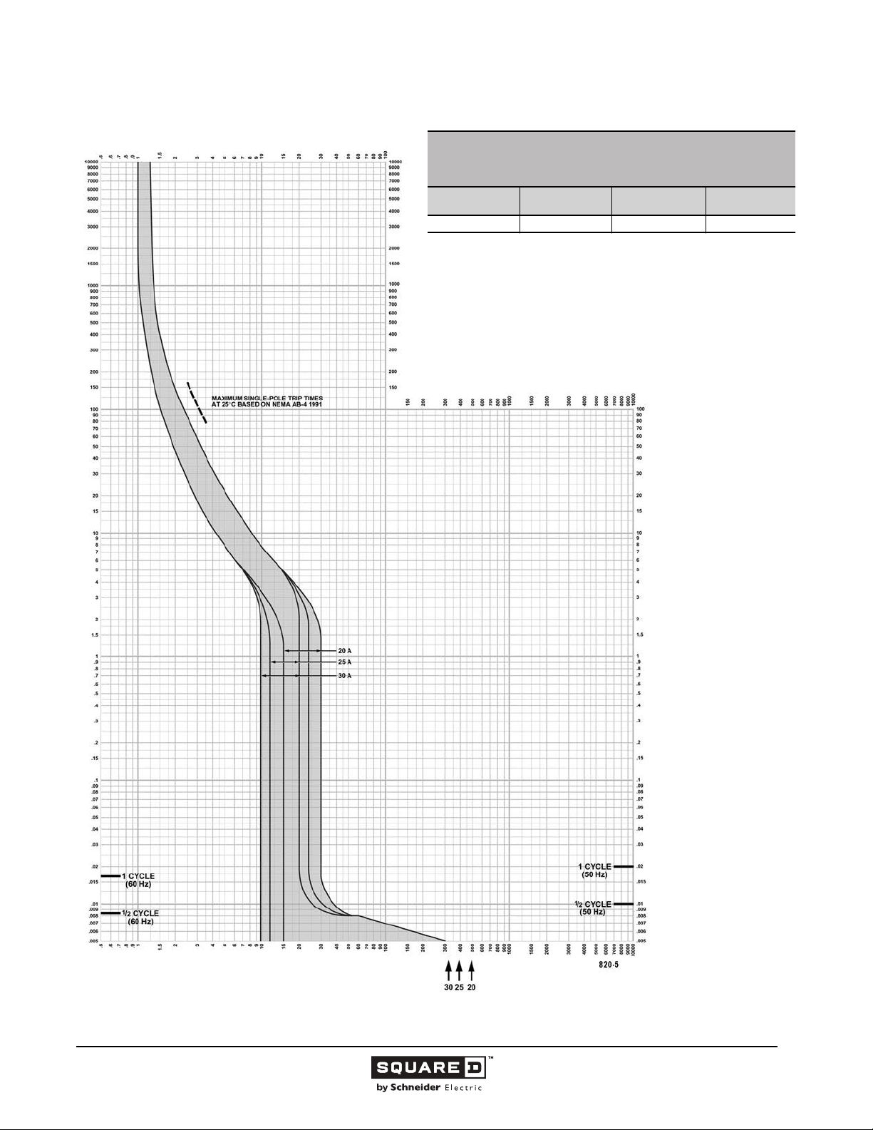
Legacy Thermal-Magnetic / Magnetic Only Molded Case Circuit Breakers
MULTIPLES OF RATED CURRENT
I-LIMITER CURRENT LIMITING CIRCUIT BREAKERS
CHARACTERISTIC TRIP CURVE NO. 820-5
CIRCUIT BREAKER INFORMATION
Circuit Breaker
Prefix
FI 20–30 600 2, 3
This curve is to be used for application and coordination purposes only.
The EZ-AMP overlay feature at the bottom of the page should be used during
coordination studies.
All time/current characteristic curve data is based on 104 °F (40 °C) ambient cold
start. Terminations are made with conductors of appropriate length and ratings.
Continuous
Ampere Rating
Maximum AC
Voltage
TIME IN SECONDS
Number of Poles
TIME IN SECONDS
Tripping curves for
coordination studies are
available upon request.
Curve No. 0820TC0005
December 2000
Drawing No. B48095-820-05
(Replaces 0820TC8505)
MULTIPLES OF RATED CURRENT
© 1991–2015 Schneider Electric
All Rights Reserved
11/2015
37
Page 38
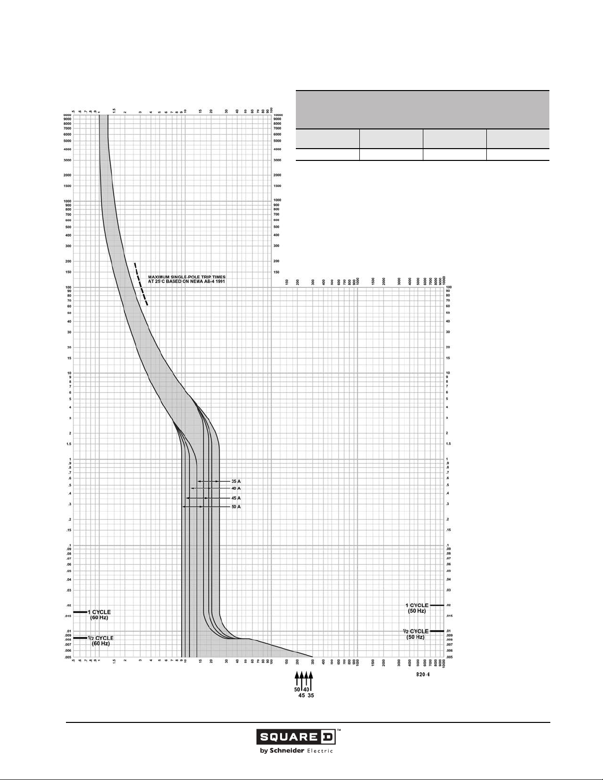
Legacy Thermal-Magnetic / Magnetic Only Molded Case Circuit Breakers
MULTIPLES OF RATED CURRENT
I-LIMITER CURRENT LIMITING CIRCUIT BREAKERS
CHARACTERISTIC TRIP CURVE NO. 820-6
CIRCUIT BREAKER INFORMATION
Circuit Breaker
Prefix
FI 35–50 600 2, 3
This curve is to be used for application and coordination purposes only.
The EZ-AMP overlay feature at the bottom of the page should be used during
coordination studies.
All time/current characteristic curve data is based on 104 °F (40 °C) ambient cold
start. Terminations are made with conductors of appropriate length and ratings.
Continuous
Ampere Rating
Maximum AC
Voltage
TIME IN SECONDS
Number of Poles
TIME IN SECONDS
Tripping curves for
coordination studies are
available upon request.
Curve No. 0820TC0006
December 2000
Drawing No. B48095-820-06
(Replaces 0820TC8506)
MULTIPLES OF RATED CURRENT
38
11/2015 © 1991–2015 Schneider Electric
All Rights Reserved
Page 39
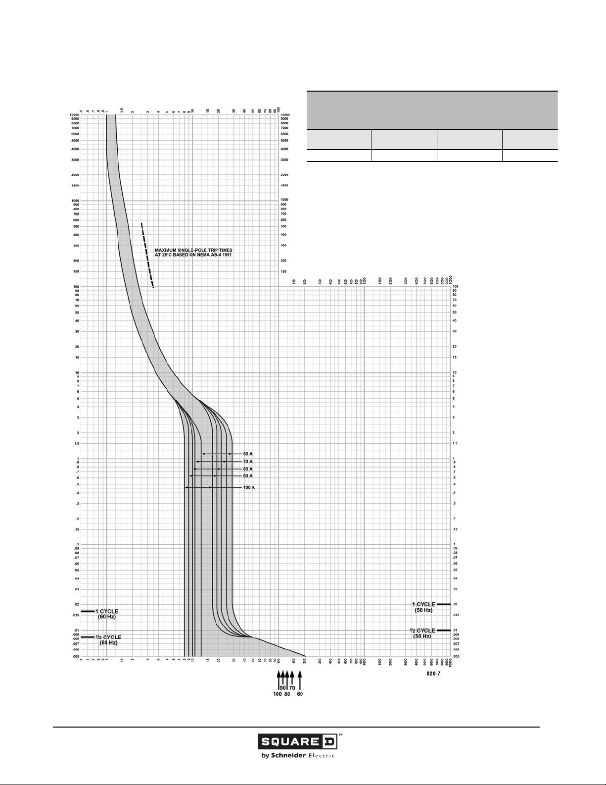
Legacy Thermal-Magnetic / Magnetic Only Molded Case Circuit Breakers
e
MULTIPLES OF RATED CURRENT
I-LIMITER CURRENT LIMITING CIRCUIT BREAKERS
CHARACTERISTIC TRIP CURVE NO. 820-7
CIRCUIT BREAKER INFORMATION
Circuit Breaker
Prefix
FI 60–100 600 2, 3
This curve is to be used for application and coordination purposes only.
The EZ-AMP overlay feature at the bottom of the page should be used during
coordination studies.
All time/current characteristic curve data is based on 104 °F (40 °C) ambient cold
start. Terminations are made with conductors of appropriate length and ratings.
Continuous
Ampere Rating
Maximum AC
Voltage
TIME IN SECONDS
Number of Pol
TIME IN SECONDS
Tripping curves for
coordination studies are
available upon request.
Curve No. 0820TC0007
December 2000
Drawing No. B48095-820-07
(Replaces 0820TC8507)
MULTIPLES OF RATED CURRENT
© 1991–2015 Schneider Electric
All Rights Reserved
11/2015
39
Page 40
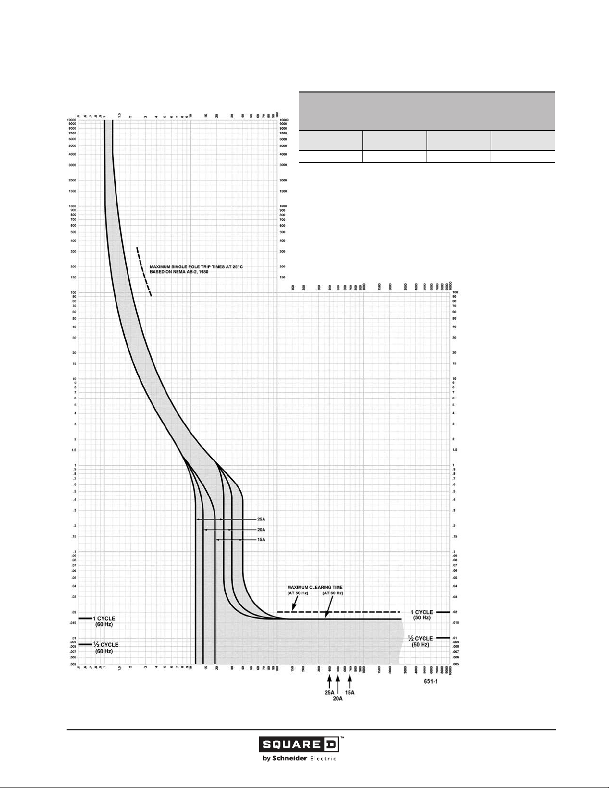
Legacy Thermal-Magnetic / Magnetic Only Molded Case Circuit Breakers
MULTIPLES OF RATED CURRENT
FY THERMAL-MAGNETIC MOLDED CASE CIRCUIT BREAKERS
CHARACTERISTIC TRIP CURVE NO. 651-1
CIRCUIT BREAKER INFORMATION
Circuit Breaker
Prefix
FY 15–25 277 1
This curve is to be used for application and coordination purposes only.
The EZ-AMP overlay feature at the bottom of the page should be used during
coordination studies.
All time/current characteristic curve data is based on 104 °F (40 °C) ambient cold
start. Terminations are made with conductors of appropriate length and ratings.
Continuous
Ampere Rating
Maximum AC
Voltage
TIME IN SECONDS
Number of Poles
TIME IN SECONDS
Tripping curves for
coordination studies are
available upon request.
Curve No. 0651TC9201
Drawing No. B48095-651-01
MULTIPLES OF RATED CURRENT
40
11/2015 © 1991–2015 Schneider Electric
All Rights Reserved
Page 41
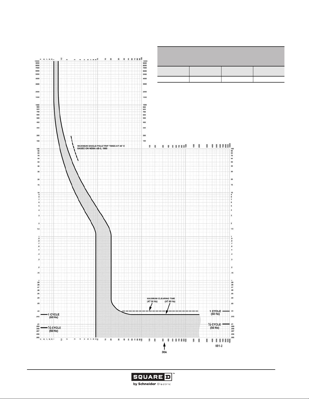
Legacy Thermal-Magnetic / Magnetic Only Molded Case Circuit Breakers
MULTIPLES OF RATED CURRENT
FY THERMAL-MAGNETIC MOLDED CASE CIRCUIT BREAKERS
CHARACTERISTIC TRIP CURVE NO. 651-2
CIRCUIT BREAKER INFORMATION
Circuit Breaker
Prefix
FY 30 277 1
This curve is to be used for application and coordination purposes only.
The EZ-AMP overlay feature at the bottom of the page should be used during
coordination studies.
All time/current characteristic curve data is based on 104 °F (40 °C) ambient cold
start. Terminations are made with conductors of appropriate length and ratings.
Continuous
Ampere Rating
Maximum AC
Voltage
TIME IN SECONDS
Number of Poles
TIME IN SECONDS
Tripping curves for
coordination studies are
available upon request.
Curve No. 0651TC9202
Drawing No. B48095-651-02
MULTIPLES OF RATED CURRENT
© 1991–2015 Schneider Electric
All Rights Reserved
11/2015
41
Page 42
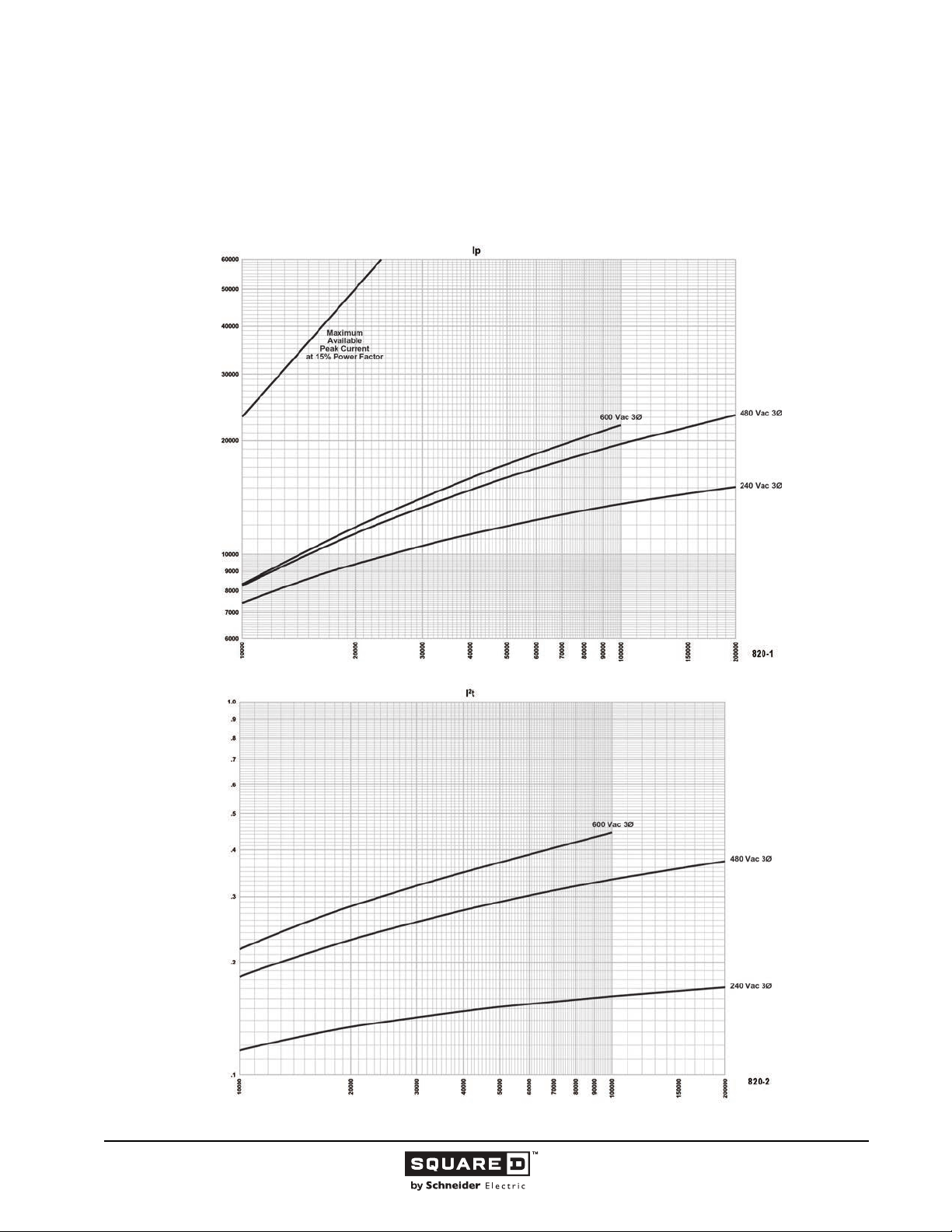
Legacy Thermal-Magnetic / Magnetic Only Molded Case Circuit Breakers
Let-through Curves
I-LIMITER CURRENT LIMITING CIRCUIT BREAKERS
FI 100 A Frame at 240, 480 and 600 Vac, 3Ø
20 A
Curve No. 820-1 Peak Let-Through Current I
Peak Let-Through Current (Amperes)
H
development and UL test programs.
and 820-2 Let-Through I2t
p
Curve No. 820-1
Maximum
Based on typical values obtained throughout the circuit breaker
H
Available Short Circuit Current (RMS Symmetrical Amperes)
)
6
Seconds x 10
2
t (Amperes
2
Let-Through I
development and UL test programs.
H
Curve No. 820-2
Maximum
Based on maximum values obtained throughout the circuit breaker
H
Available Short Circuit Current (RMS Symmetrical Amperes)
42
11/2015 © 1991–2015 Schneider Electric
All Rights Reserved
Page 43
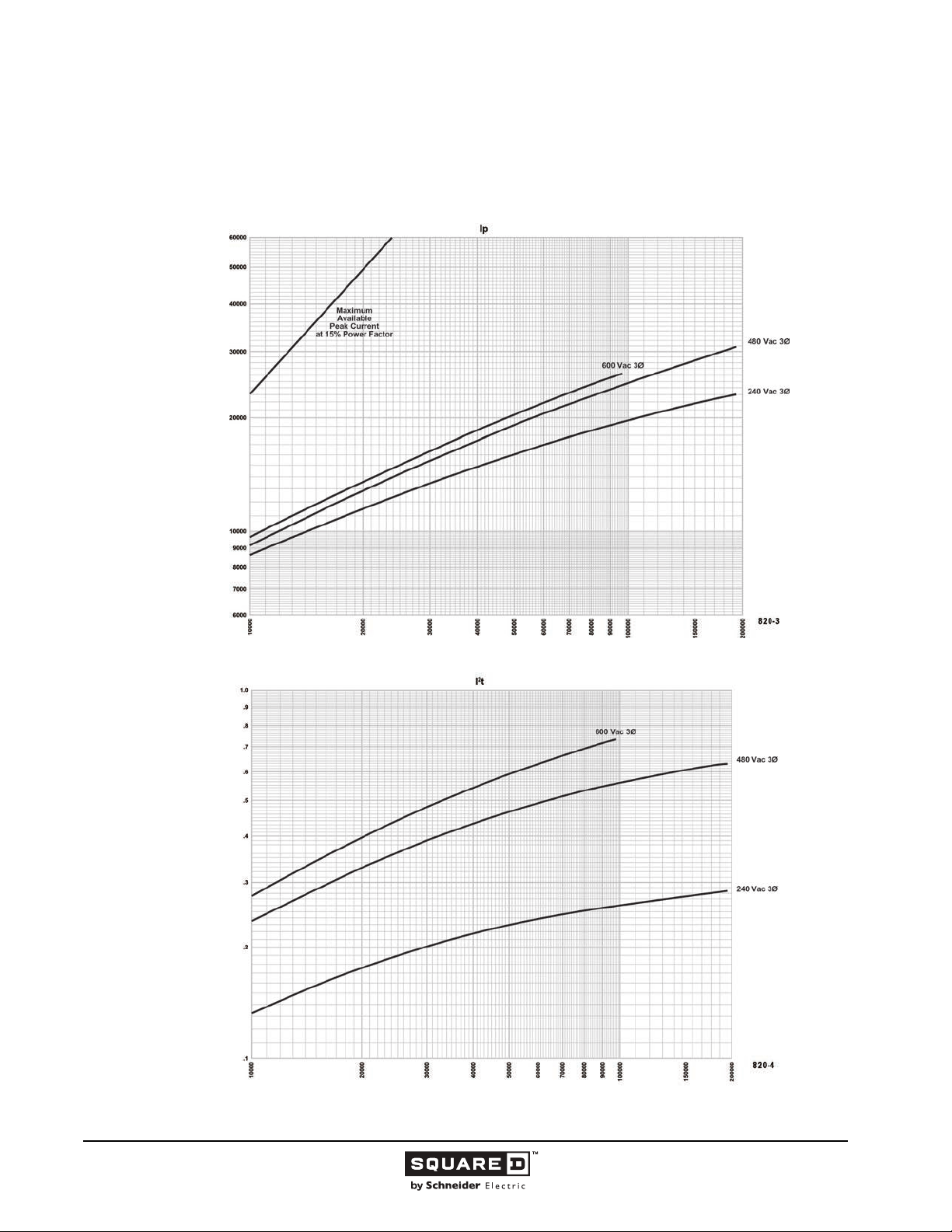
Legacy Thermal-Magnetic / Magnetic Only Molded Case Circuit Breakers
I-LIMITER® CURRENT LIMITING CIRCUIT BREAKERS
FI 100 A Frame at 240, 480 and 600 Vac, 3Ø
Curve No. 820-3 Peak Let-Through Current I
Peak Let-Through Current (Amperes)
H
development and UL test programs.
25–100 A
p
and 820-4 Let-Through I2t
Curve No. 820-3
Maximum
Based on typical values obtained throughout the circuit breaker
H
Available Short Circuit Current (RMS Symmetrical Amperes)
)
6
Seconds x 10
2
t (Amperes
2
Let-Through I
development and UL test programs.
H
Curve No. 820-4
Maximum
Based on maximum values obtained throughout the circuit breaker
H
© 1991–2015 Schneider Electric
All Rights Reserved
Available Short Circuit Current (RMS Symmetrical Amperes)
43
11/2015
Page 44
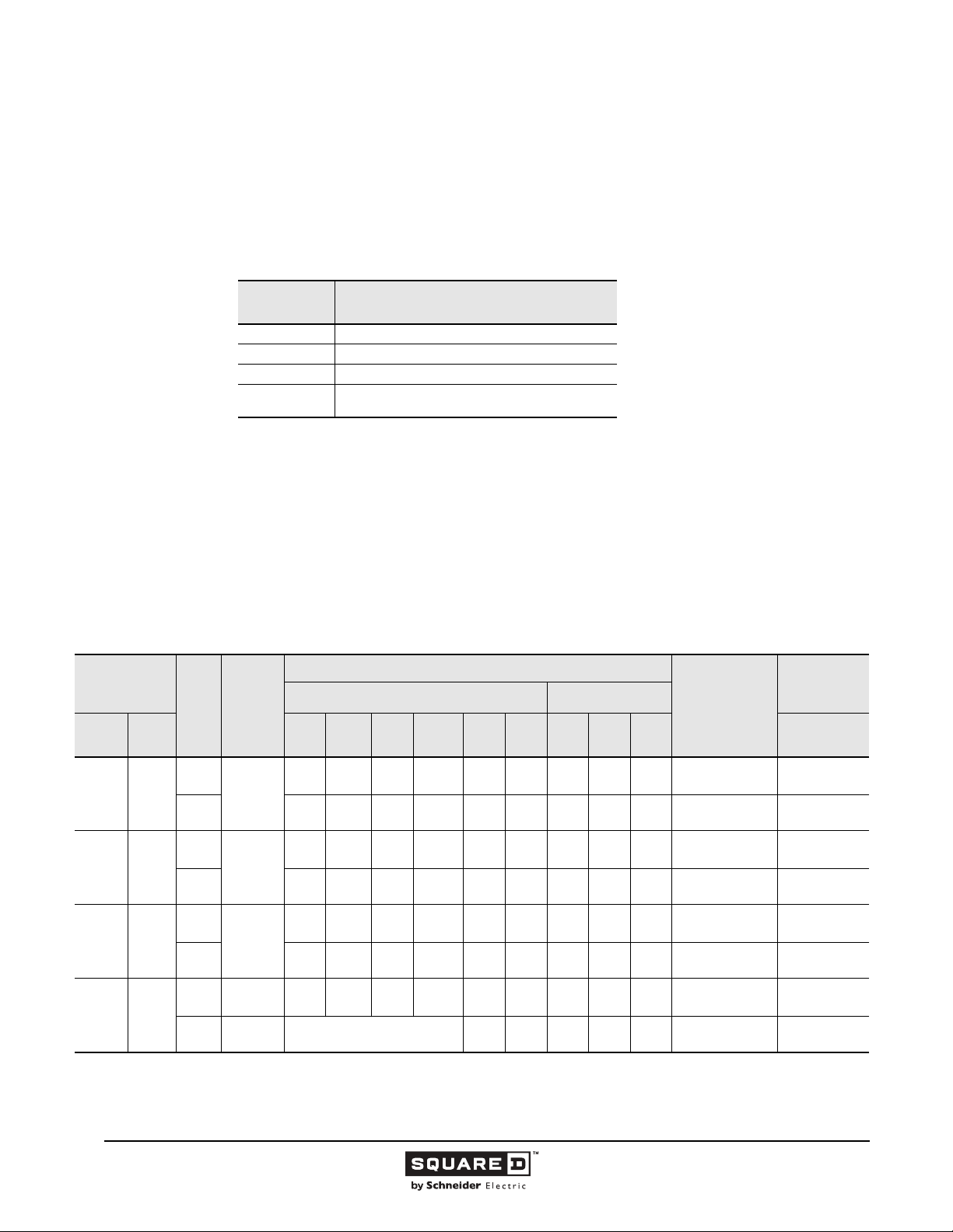
Legacy Thermal-Magnetic / Magnetic Only Molded Case Circuit Breakers
225 / 250 Ampere Frame
This section provides specific information on Schneider Electric 225 / 250 A frame thermal-magnetic
molded case circuit breakers. For more information, see the “Introduction” in this catalog.
Description
Table 14: Description of 225 / 250 A Frame Circuit Breakers
Circuit
Breaker
QB, QD, QG, QJ 100–225 A, 240 Vac, 50/60 Hz, two- and three-pole.
KA/KH 70–250 A, 600 Vac, 50/60 Hz two- and three-pole
KC 110–250 A, 480 Vac 50/60 Hz, two- and three-pole
KI
110–250 A, 600 Vac, 50/60 Hz, two- and three-pole
Description
current limiting
Applications
• KI current limiting circuit breakers are used for electrical systems where high fault currents can
occur.
• KA/KH, KC and KI circuit breakers are used in industrial enclosures, panelboards, switchboards,
busway plug-in units, combination starters and motor control centers.
• QB, QD, QG, QJ (250 A Q-frame) circuit breakers are used in individual enclosures, metering
devices, panelboards 225 A maximum I-Line, and switchboards.
.
Table 15: 250 A PowerPact Q-frame Interrupting Ratings (225 A I-Line)
Catalog
Number Prefix
No. of
Poles
Unit
Mount
QBM
QMP
QDM
QGM
QGP
1
2
I-Line 120
QBL
QBA
QBE
QBF
QDL
QDA
QDP
QDF
QGL
QGF
QJL
QJM
QJP
QJF
See Class 611, 612, 613, and 734 catalogs for other PowerPact and Masterpact circuit breakers.
225 A I-Line.
QDE
QGA
QGE
QJA
QJE
Cont.
Ampere
AC Volts - RMS Symmetrical Amperes DC Volts
Rating
2
70–250
3 — — 10 — — — — — — 12b 10/5
2
70–250
3 — — 25 — — — — — — 14b 10/5
2
70–250
3 — — 65 — — — — — — 15b 10/5
2
70–250
3 70–250
— — 10 — — — — — — 12b 10/5
2
— — 25 — — — — — — 14b 10/5
2
— — 65 — — — — — — 15b 10/5
2
2
— — 100 — — — — — — 15b 10/5
2
208Y/120 Vac: 100 kA — — — — — — 10/5
UL Listed Interrupting Rating (kA)
120/
240
240
480Y/
277
480 600 125 250 500 415/240
1
IEC 60947-2
Icu/Ics (kA)
Federal Specs.
AC Voltage
W-C-375B/GEN
44
11/2015 © 1991–2015 Schneider Electric
All Rights Reserved
Page 45
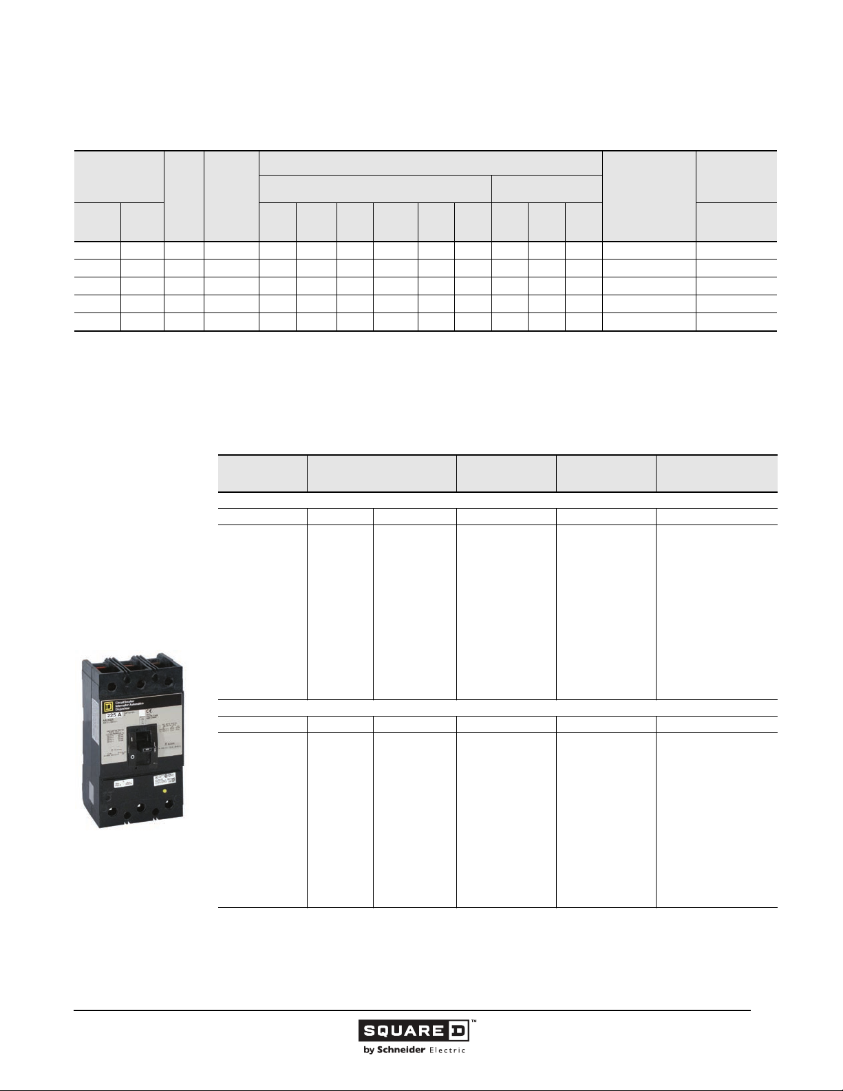
Legacy Thermal-Magnetic / Magnetic Only Molded Case Circuit Breakers
Table 16: 250 A Frame Interrupting Ratings
Catalog
Number Prefix
No. of
Poles
Unit
Mount
KHL
KHL-DC
1
2
I-Line 120
KAL KA 2, 3 70–250 42 42 42 25 25 22 10 10 — 19a, 20a 10/2.5
KCL KC 2, 3 110–250 100 100 100 65 65 — — — — 23a 65/65
KIL KI 2, 3 110–250 200 200 200 200 200 100 — — — 16a 130/65
Separate UL rating available for 240 Vac and 480 Vac grounded B single phase systems. Circuit breakers must be ordered with 5861 suffix.
UL listed 500 Vdc rating for use on ungrounded systems. Must be connected three-poles in series. Consult the Schneider Electric Customer Care Center for
additional information
1
1
KH
2
2, 3 70–250 65 65 65 35 35 25 10 10 — 23a 10/2.5
—3 — ————————20 — —
Cont.
Ampere
Rating
AC Volts - RMS Symmetrical Amperes DC Volts
UL Listed Interrupting Rating (kA)
120/
240
240
480Y/
277
480 600 125 250 500 415/240
Federal Specs.
W-C-375B/GEN
IEC 60947-2
Icu/Ics (kA)
AC Voltage
Selection Data
Table 17: 250 A Frame Unit Mount Circuit Breakers
KAL/KHL Two- and
Three-pole
70–250 A
Ampere Rating
KAL Standard Interrupting
70
80
90
100
110
125
150
175
200
225
250
KHL High Interrupting
70
80
90
100
110
125
150
175
200
225
250
1
UL magnetic trip setting tolerances are -20% /+30% (Low) and -20% /+30% (High) from the nominal values shown.
AC Magnetic Trip Settings
Amperes
Low High 600 Vac/250 Vdc 600 Vac/250 Vdc
350
400
450
500
550
625
750
875
1000
1125
1250
Low High 600 Vac/250 Vdc 600 Vac/250 Vdc
350
400
450
500
550
625
750
875
1000
1125
1250
1
700
800
900
1000
1100
1250
1500
1750
2000
2250
2500
700
800
900
1000
1100
1250
1500
1750
2000
2250
2500
Two-Pole
Catalog No.
KAL26070
KAL26080
KAL26090
KAL26100
KAL26110
KAL26125
KAL26150
KAL26175
KAL26200
KAL26225
KAL26250
KHL26070
KHL26080
KHL26090
KHL26100
KHL26110
KHL26125
KHL26150
KHL26175
KHL26200
KHL26225
KHL26250
Three-Pole
Catalog No.
KAL36070
KAL36080
KAL36090
KAL36100
KAL36110
KAL36125
KAL36150
KAL36175
KAL36200
KAL36225
KAL36250
KHL36070
KHL36080
KHL36090
KHL36100
KHL36110
KHL36125
KHL36150
KHL36175
KHL36200
KHL36225
KHL36250
Standard Lug Kit Wire
Range
AL250KA
1-#6-350 kcmil
AL250KA
1-#6-350 kcmil
—Continued on next page
© 1991–2015 Schneider Electric
All Rights Reserved
11/2015
45
Page 46
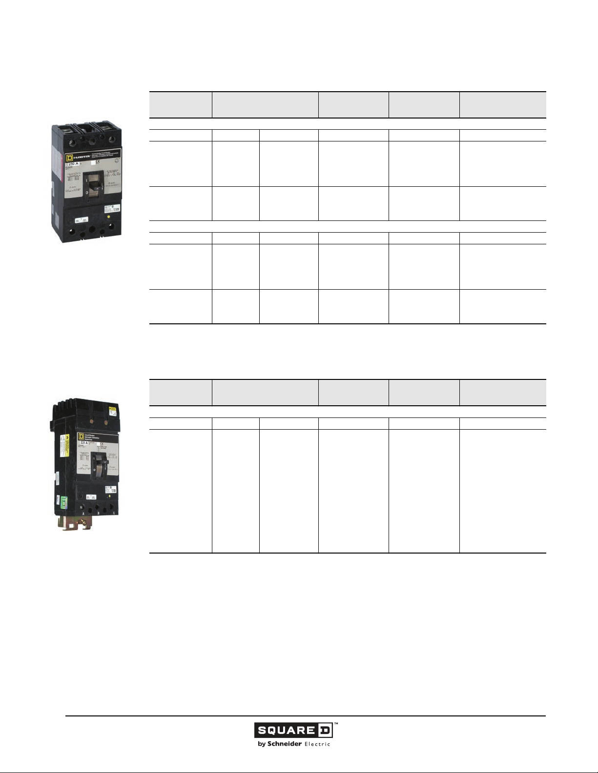
Legacy Thermal-Magnetic / Magnetic Only Molded Case Circuit Breakers
Table 17: 250 A Frame Unit Mount Circuit Breakers (continued)
KIL Two- and Three-pole
110–250 A
Ampere Rating
KCL Extra High Interrupting
110
125
150
175
200
225
250
KIL I-Limiter Current Limiting
110
125
150
175
200
225
250
1
UL magnetic trip setting tolerances are -20% /+30% (Low) and -20% /+30% (High) from the nominal values shown.
AC Magnetic Trip Settings
Amperes
Low High 480 Vac 480 Vac
550
625
750
875
1000
1125
1250
Low High 600 Vac 600 Vac
550
625
750
875
1000
1125
1250
1
1100
1250
1500
1750
2000
2250
2500
1100
1250
1500
1750
2000
2250
2500
Two-Pole
Catalog No.
KCL24110
KCL24125
KCL24150
KCL24175
KCL24200
KCL24225
KCL24250
KIL26110
KIL26125
KIL26150
KIL26175
KIL26200
KIL26225
KIL26250
Three-Pole
Catalog No.
KCL34110
KCL24125
KCL34150
KCL34175
KCL34200
KCL34225
KCL34250
KIL36110
KIL36125
KIL36150
KIL36175
KIL36200
KIL36225
KIL36250
Standard Lug Kit Wire
Table 18: 250 A Frame I-Line Circuit Breakers
Range
AL250KA
1-#6-350 kcmil
AL250KI
1-1/0-350 kcmil
AL250KA
1-#6-350 kcmil
AL250KI
1-1/0-350 kcmil
KA Two- and Three-pole
70–250 A
4-1/2 in. Mounting Height
Ampere Rating
KA Standard Interrupting
70
80
90
100
110
125
150
175
200
225
250
1
UL magnetic trip setting tolerances are -20% /+30% (Low) and -20% /+30% (High) from the nominal values shown.
2
Two-pole circuit breaker catalog numbers are completed by adding required phase connection letters as a suffix to the catalog
number.
AC Magnetic Trip Settings
Amperes
Low High 600 Vac/250 Vdc 600 Vac/250 Vdc
350
400
450
500
550
625
750
875
1000
1125
1250
1
700
800
900
1000
1100
1250
1500
1750
2000
2250
2500
Two-Pole
Catalog No.
KA26070( )
KA26080( )
KA26090( )
KA26100( )
KA26110( )
KA26125( )
KA26150( )
KA26175( )
KA26200( )
KA26225( )
KA26250( )
2
Three-Pole
Catalog No.
KA36070
KA36080
KA36090
KA36100
KA36110
KA36125
KA36150
KA36175
KA36200
KA36225
KA36250
Standard Lug Kit Wire
Range
AL250KA
1-#6-350 kcmil
—Continued on next page
46
11/2015 © 1991–2015 Schneider Electric
All Rights Reserved
Page 47
Legacy Thermal-Magnetic / Magnetic Only Molded Case Circuit Breakers
Table 18: 250 A Frame I-Line Circuit Breakers (continued)
KI Two- and Three-pole
110–250 A
4-1/2 in. Mounting Height
Ampere Rating
KH High Interrupting
70
80
90
100
110
125
150
175
200
225
250
KC Extra High Interrupting
110
125
150
175
200
225
250
KI I-Limiter Current Limiting
110
125
150
175
200
225
250
1
UL magnetic trip setting tolerances are -20% /+30% (Low) and -20% /+30% (High) from the nominal values shown.
2
Two-pole circuit breaker catalog numbers are completed by adding required phase connection letters as a suffix to the catalog
number.
AC Magnetic Trip Settings
Amperes
Low High 600 Vac/250 Vdc 600Vac/250Vdc
350
400
450
500
550
625
750
875
1000
1125
1250
Low High 480 Vac 480 Vac
550
625
750
875
1000
1125
1250
Low High 600 Vac 600 Vac
550
625
750
875
1000
1125
1250
1
700
800
900
1000
1100
1250
1500
1750
2000
2250
2500
1100
1250
1500
1750
2000
2250
2500
1100
1250
1500
1750
2000
2250
2500
Two-Pole
Catalog No.
KH26070( )
KH26080( )
KH26090( )
KH26100( )
KH26110( )
KH26125( )
KH26150( )
KH26175( )
KH26200( )
KH26225( )
KH26250( )
KC24110( )
KC24125( )
KC24150( )
KC24175( )
KC24200( )
KC24225( )
KC24250( )
KI26110( )
KI26125( )
KI26150( )
KI26175( )
KI26200( )
KI26225( )
KI26250( )
2
Three-Pole
Catalog No.
KH36070
KH36080
KH36090
KH36100
KH36110
KH36125
KH36150
KH36175
KH36200
KH36225
KH36250
KC34110
KC34125
KC34150
KC34175
KC34200
KC34225
KC34250
KI36110
KI36125
KI36150
KI36175
KI36200
KI36225
KI36250
Standard Lug Kit Wire
Range
AL250KA
1-#6-350 kcmil
AL250KA
1-#6-350 kcmil
AL250KI
1-1/0-350 kcmil
AL250KA
1-#6-350 kcmil
AL250KI
1-1/0-350 kcmil
© 1991–2015 Schneider Electric
All Rights Reserved
11/2015
47
Page 48
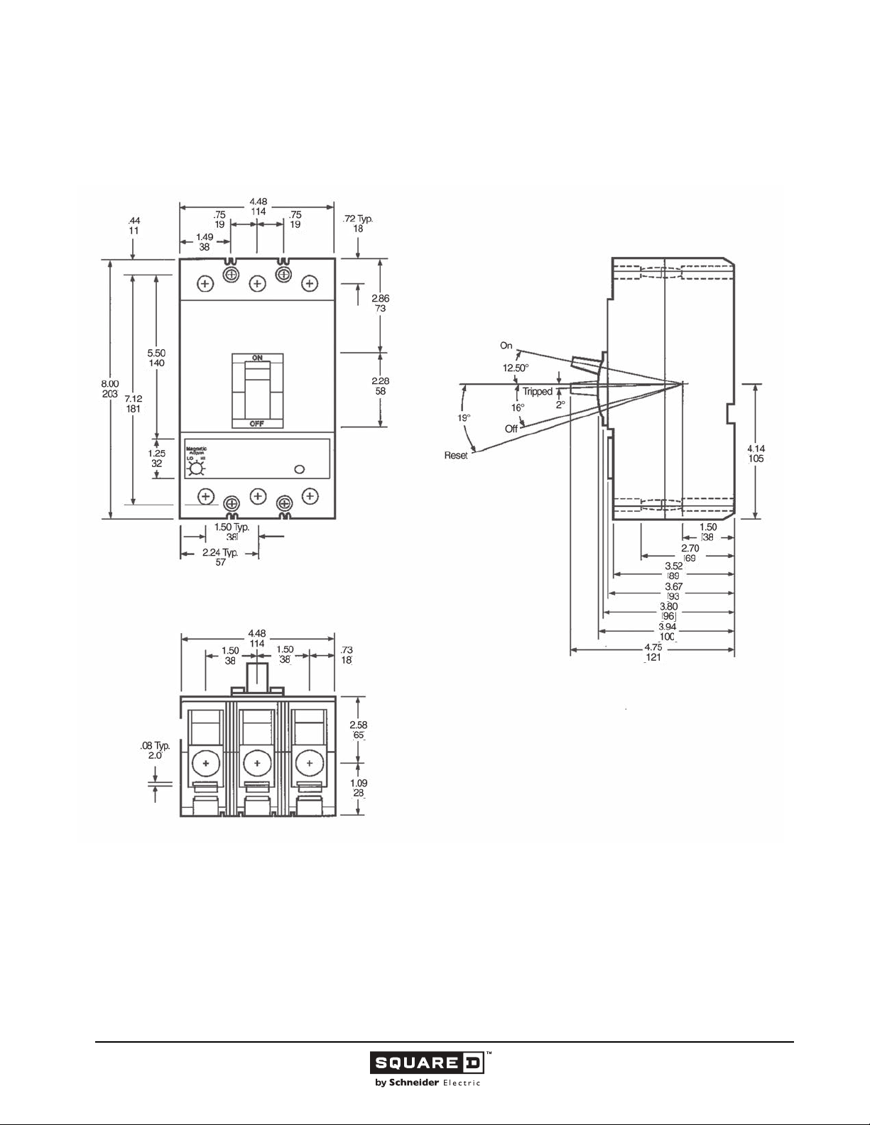
Legacy Thermal-Magnetic / Magnetic Only Molded Case Circuit Breakers
Dimensions
Figure 13: KAL, KHL, KCL, KIL 250 A Frame
( )
( )
( )
( )
( )
( )
( )
( )
( )
( )
( )
( )
( )
( )
( )
( )
( )
( )
( )
( )
( )
( )
( )
( )
( )
( )
( )
( )
( )
Dimensions:
48
11/2015 © 1991–2015 Schneider Electric
All Rights Reserved
in.
(mm)
Page 49
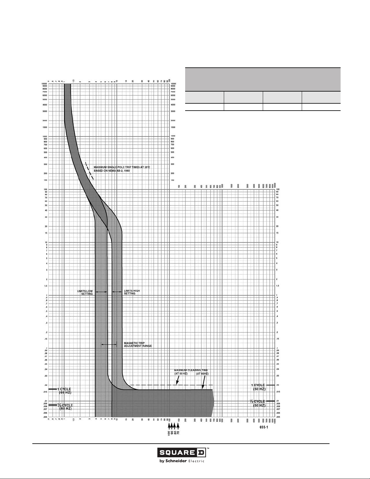
Legacy Thermal-Magnetic / Magnetic Only Molded Case Circuit Breakers
Tripping Curves
MULTIPLES OF RATED CURRENT
KA/KH FAMILY MOLDED CASE CIRCUIT BREAKERS
CHARACTERISTIC TRIP CURVE NO. 655-1
CIRCUIT BREAKER INFORMATION
Circuit Breaker
Prefix
KA/KH 70–100 600 2, 3
This curve is to be used for application and coordination purposes only.
The EZ-AMP overlay feature at the bottom of the page should be used during
coordination studies.
All time/current characteristic curve data is based on 104 °F (40 °C) ambient cold
start. Terminations are made with conductors of appropriate length and ratings.
Continuous
Ampere Rating
Maximum AC
Voltage
TIME IN SECONDS
Number of Poles
TIME IN SECONDS
MULTIPLES OF RATED CURRENT
© 1991–2015 Schneider Electric
All Rights Reserved
Tripping curves for
coordination studies are
available upon request.
Curve No. 655-1
May 1985
49
11/2015
Page 50
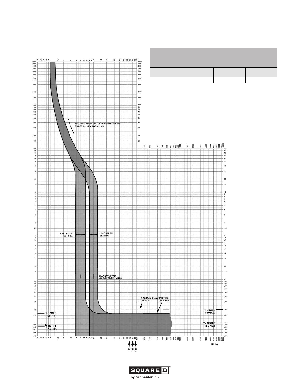
Legacy Thermal-Magnetic / Magnetic Only Molded Case Circuit Breakers
MULTIPLES OF RATED CURRENT
KA/KH FAMILY MOLDED CASE CIRCUIT BREAKERS
CHARACTERISTIC TRIP CURVE NO. 655-2
CIRCUIT BREAKER INFORMATION
Circuit Breaker
Prefix
KA/KH 110–150 600 2, 3
This curve is to be used for application and coordination purposes only.
The EZ-AMP overlay feature at the bottom of the page should be used during
coordination studies.
All time/current characteristic curve data is based on 104 °F (40 °C) ambient cold
start. Terminations are made with conductors of appropriate length and ratings.
Continuous
Ampere Rating
Maximum AC
Voltage
TIME IN SECONDS
Number of Poles
TIME IN SECONDS
MULTIPLES OF RATED CURRENT
Tripping curves for
coordination studies are
available upon request.
Curve No. 0655TC8502
Drawing No. B48095-655-02
© 1991–2015 Schneider Electric
All Rights Reserved
11/2015
50
Page 51
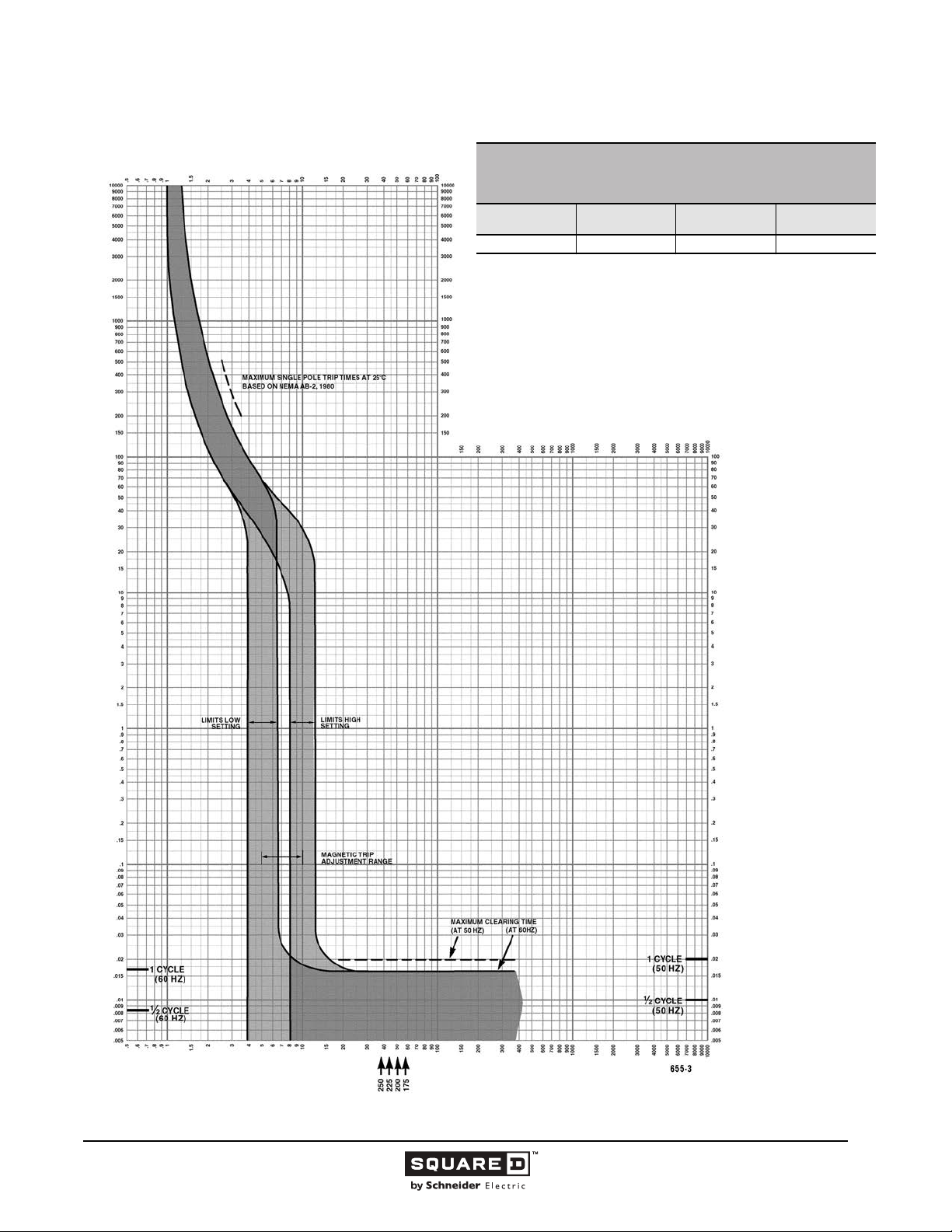
Legacy Thermal-Magnetic / Magnetic Only Molded Case Circuit Breakers
MULTIPLES OF RATED CURRENT
KA/KH FAMILY MOLDED CASE CIRCUIT BREAKERS
CHARACTERISTIC TRIP CURVE NO. 655-3
CIRCUIT BREAKER INFORMATION
Circuit Breaker
Prefix
KA/KH 175–250 600 2, 3
This curve is to be used for application and coordination purposes only.
The EZ-AMP overlay feature at the bottom of the page should be used during
coordination studies.
All time/current characteristic curve data is based on 104 °F (40 °C) ambient cold
start. Terminations are made with conductors of appropriate length and ratings.
Continuous
Ampere Rating
Maximum AC
Voltage
TIME IN SECONDS
Number of Poles
TIME IN SECONDS
MULTIPLES OF RATED CURRENT
Tripping curves for
coordination studies are
available upon request.
Curve No. 0655TC8803
Drawing No. B48095-655-03
© 1991–2015 Schneider Electric
All Rights Reserved
11/2015
51
Page 52
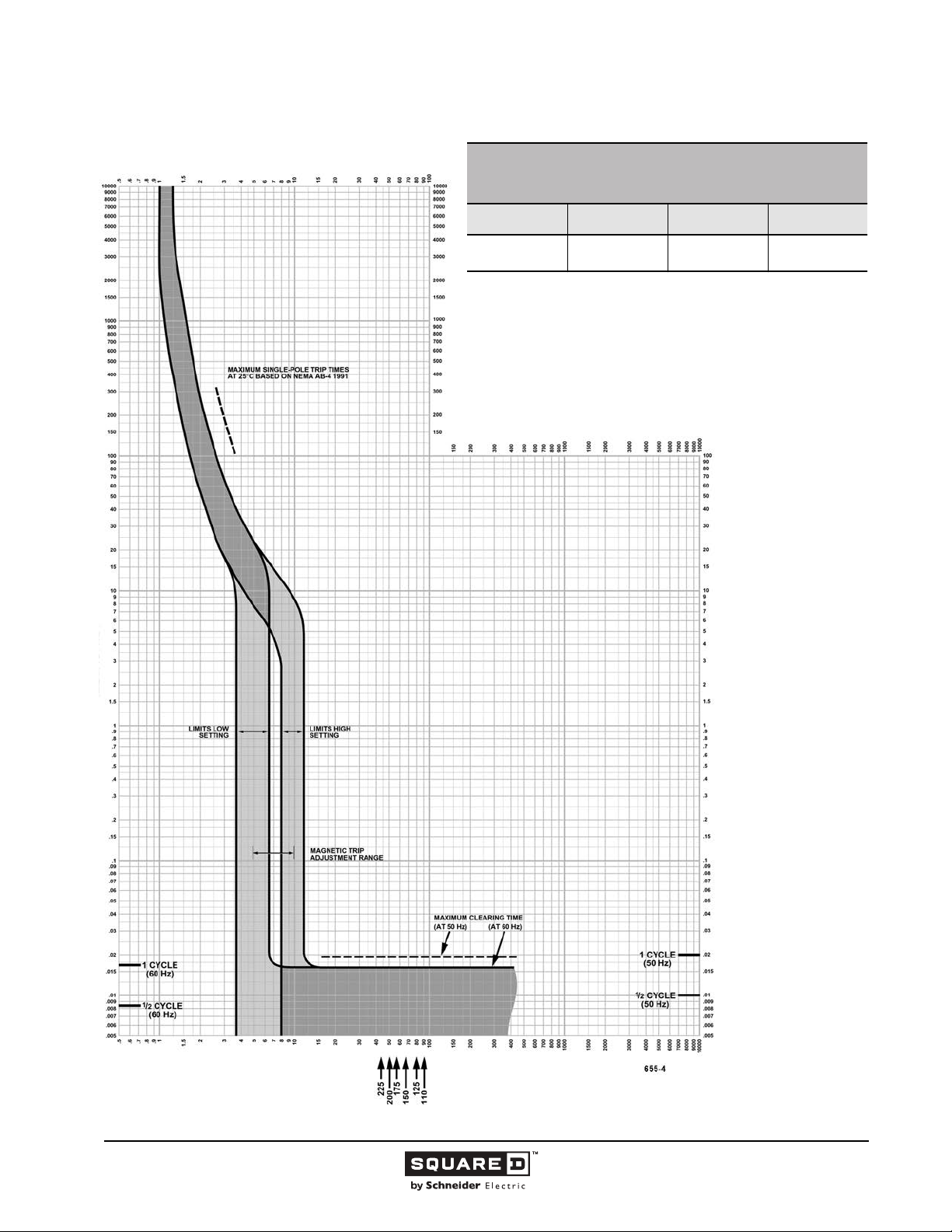
Legacy Thermal-Magnetic / Magnetic Only Molded Case Circuit Breakers
MULTIPLES OF RATED CURRENT
KC FAMILY MOLDED CASE CIRCUIT BREAKERS
CHARACTERISTIC TRIP CURVE NO. 655-4
CIRCUIT BREAKER INFORMATION
Circuit Breaker
Prefix
KC
KC
This curve is to be used for application and coordination purposes only.
The EZ-AMP overlay feature at the bottom of the page should be used during
coordination studies.
All time/current characteristic curve data is based on 104 °F (40 °C) ambient cold
start. Terminations are made with conductors of appropriate length and ratings.
Continuous
Ampere Rating
110–225
Maximum AC
Voltage
240
480
TIME IN SECONDS
Number of Poles
2, 3
TIME IN SECONDS
MULTIPLES OF RATED CURRENT
Tripping curves for
coordination studies
are available upon
request.
Curve No. 0655TC0004
December 2000
Drawing No. B48095-655-04
(Replaces 0655TC8904)
52
11/2015 © 1991–2015 Schneider Electric
All Rights Reserved
Page 53
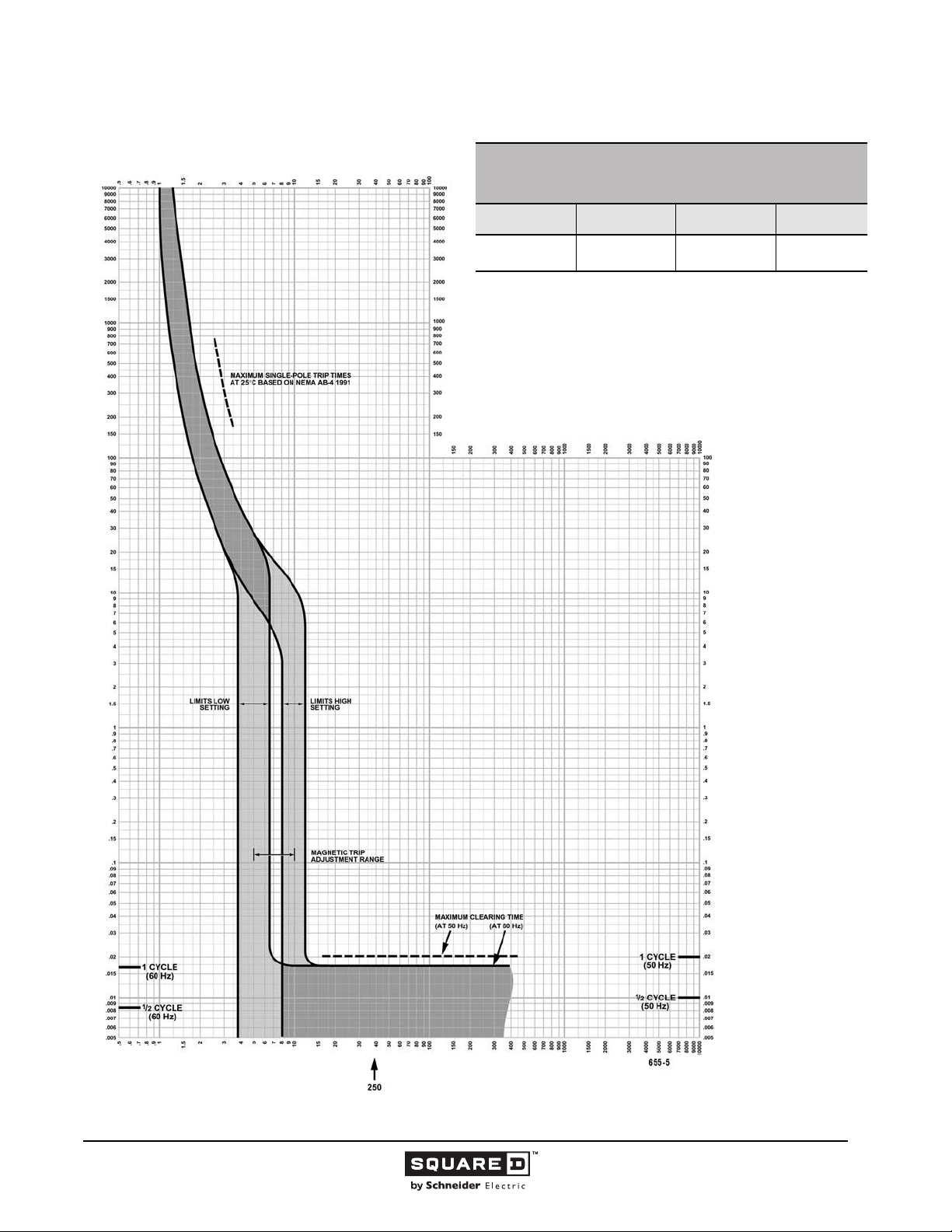
Legacy Thermal-Magnetic / Magnetic Only Molded Case Circuit Breakers
s
d
MULTIPLES OF RATED CURRENT
KC FAMILY MOLDED CASE CIRCUIT BREAKERS
CHARACTERISTIC TRIP CURVE NO. 655-5
CIRCUIT BREAKER INFORMATION
Circuit Breaker
Prefix
KC
KC
This curve is to be used for application and coordination purposes only.
The EZ-AMP overlay feature at the bottom of the page should be used during
coordination studies.
All time/current characteristic curve data is based on 104 °F (40 °C) ambient col
start. Terminations are made with conductors of appropriate length and ratings.
Continuous
Ampere Rating
250
Maximum AC
Voltage
240
480
TIME IN SECONDS
Number of Pole
2, 3
TIME IN SECONDS
MULTIPLES OF RATED CURRENT
Tripping curves for
coordination studies
are available upon
request.
Curve No. 0655TC0005
December 2000
Drawing No. B48095-655-05
(Replaces 0655TC8905)
© 1991–2015 Schneider Electric
All Rights Reserved
11/2015
53
Page 54
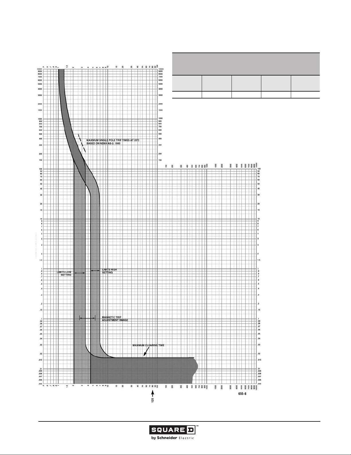
Legacy Thermal-Magnetic / Magnetic Only Molded Case Circuit Breakers
MULTIPLES OF RATED CURRENT
KH FAMILY MOLDED CASE CIRCUIT BREAKERS
CHARACTERISTIC TRIP CURVE NO. 655-6
CIRCUIT BREAKER INFORMATION
Circuit
Breaker Prefix
KH 170C 125 500 3
This curve is to be used for application and coordination purposes only.
The EZ-AMP overlay feature at the bottom of the page should be used during
coordination studies.
All time/current characteristic curve data is based on 104 °F (40 °C) ambient cold
start. Terminations are made with conductors of appropriate length and ratings.
Circuit
Breaker Suffix
Continuous
Ampere
Rating
Maximum AC
Voltage
TIME IN SECONDS
Number of
Poles
TIME IN SECONDS
MULTIPLES OF RATED CURRENT
Tripping curves for
coordination studies are
available upon request.
Curve No. 0655TC8906
Drawing No. B48095-655-06
54
11/2015 © 1991–2015 Schneider Electric
All Rights Reserved
Page 55
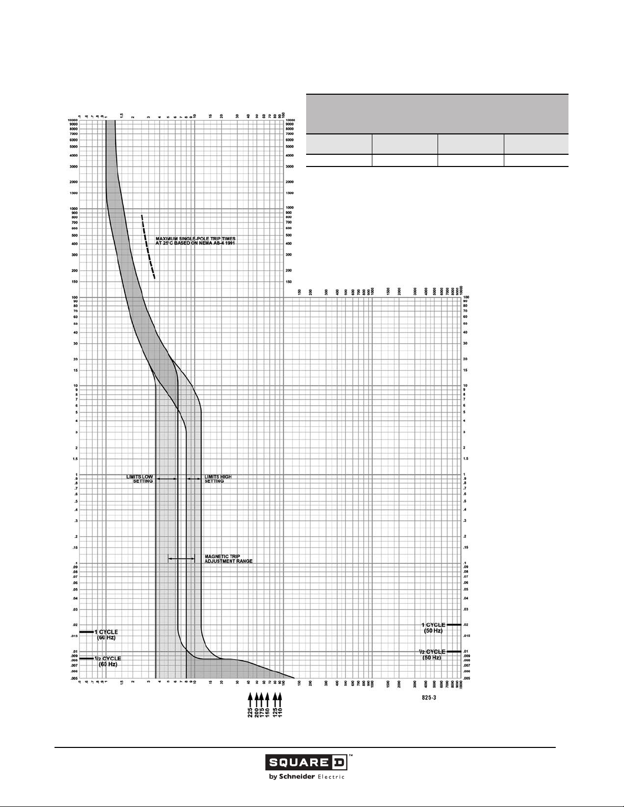
Legacy Thermal-Magnetic / Magnetic Only Molded Case Circuit Breakers
MULTIPLES OF RATED CURRENT
I-LIMITER CURRENT LIMITING CIRCUIT BREAKERS
CHARACTERISTIC TRIP CURVE NO. 825-3
CIRCUIT BREAKER INFORMATION
Circuit Breaker
Prefix
KI 110–225 600 2, 3
This curve is to be used for application and coordination purposes only.
The EZ-AMP overlay feature at the bottom of the page should be used during
coordination studies.
All time/current characteristic curve data is based on 104 °F (40 °C) ambient cold
start. Terminations are made with conductors of appropriate length and ratings.
Continuous
Ampere Rating
Maximum AC
Voltage
TIME IN SECONDS
Number of Poles
TIME IN SECONDS
MULTIPLES OF RATED CURRENT
Tripping curves for
coordination studies are
available upon request.
Curve No. 0825TC0003
December 2000
Drawing No. B48095-825-03
(Replaces 0825TC8503)
© 1991–2015 Schneider Electric
All Rights Reserved
11/2015
55
Page 56
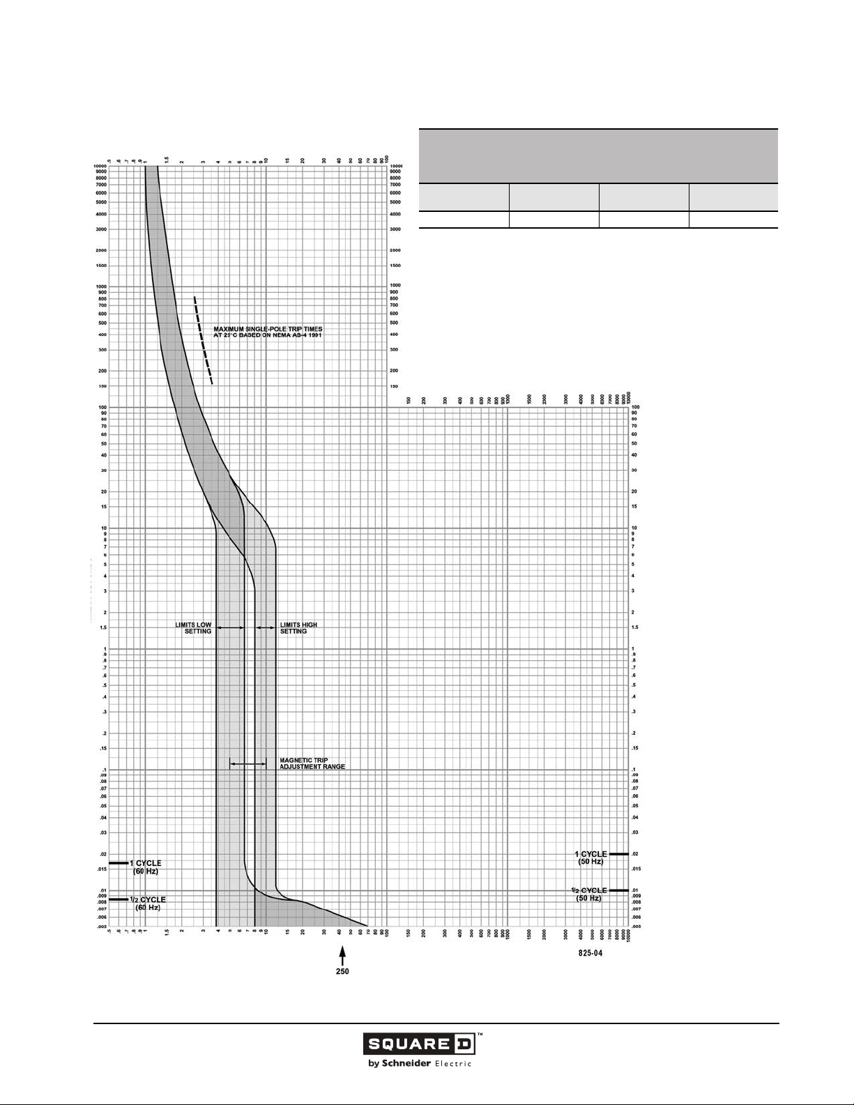
Legacy Thermal-Magnetic / Magnetic Only Molded Case Circuit Breakers
MULTIPLES OF RATED CURRENT
I-LIMITER CURRENT LIMITING CIRCUIT BREAKERS
CHARACTERISTIC TRIP CURVE NO. 825-4
CIRCUIT BREAKER INFORMATION
Circuit Breaker
Prefix
KI 250 600 2, 3
This curve is to be used for application and coordination purposes only.
The EZ-AMP overlay feature at the bottom of the page should be used during
coordination studies.
All time/current characteristic curve data is based on 104 °F (40 °C) ambient cold
start. Terminations are made with conductors of appropriate length and ratings.
Continuous
Ampere Rating
Maximum AC
Voltage
TIME IN SECONDS
Number of Poles
TIME IN SECONDS
MULTIPLES OF RATED CURRENT
Tripping curves for
coordination studies are
available upon request.
Curve No. 0825TC0004
December 2000
Drawing No. B48095-825-04
(Replaces 0825TC8504)
56
11/2015 © 1991–2015 Schneider Electric
All Rights Reserved
Page 57
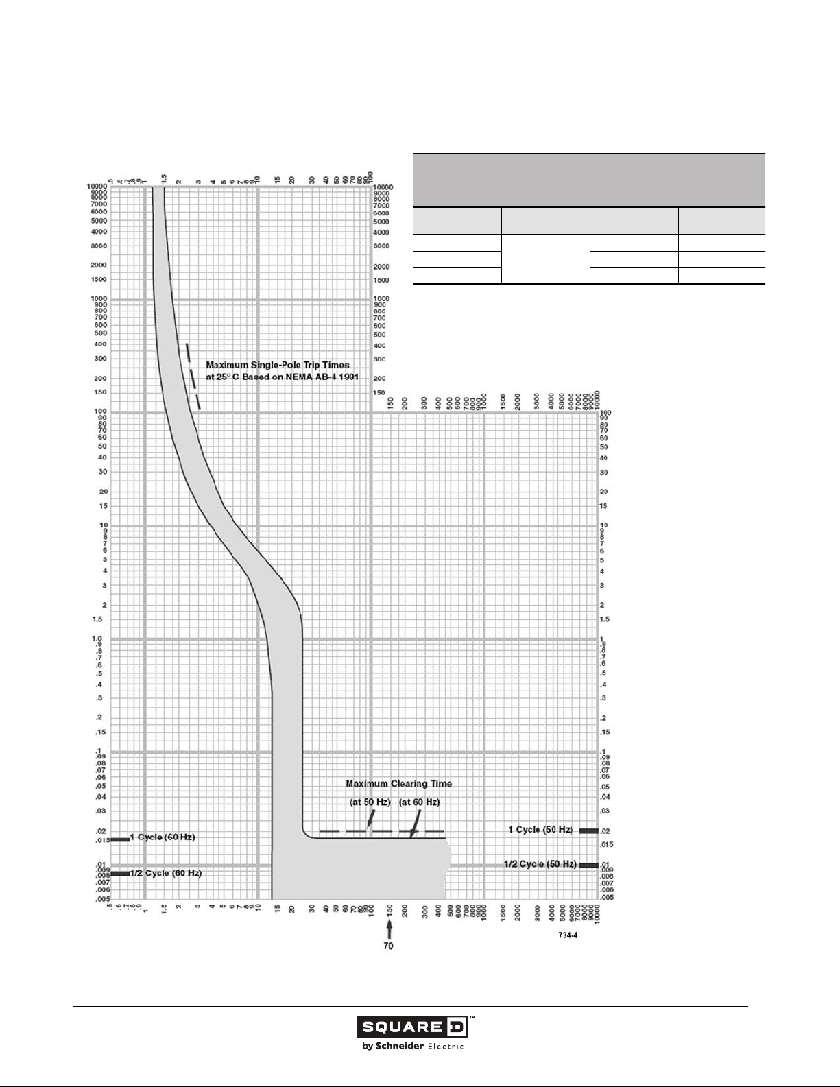
Legacy Thermal-Magnetic / Magnetic Only Molded Case Circuit Breakers
PowerPact Tripping Curves
MULTIPLES OF RATED CURRENT
POWERPACT Q-FRAME MOLDED CASE CIRCUIT BREAKERS
CHARACTERISTIC TRIP CURVE NO. 734-4
CIRCUIT BREAKER INFORMATION
Circuit Breaker
Prefix
QB, QD, QG, QJ
QB, QD, QG 240 3
QJ 208Y/120 3
This curve is to be used for application and coordination purposes only.
The EZ-AMP overlay feature at the bottom of the page should be used during
coordination studies.
All time/current characteristic curve data is based on 104 °F (40 °C) ambient cold
start. Terminations are made with conductors of appropriate length and ratings.
Continuous
Ampere Rating
70
Maximum AC
Voltage
240 2
TIME IN SECONDS
Number of Poles
TIME IN SECONDS
MULTIPLES OF RATED CURRENT
Tripping curves for
coordination studies are
available upon request.
© 1991–2015 Schneider Electric
All Rights Reserved
11/2015
57
Page 58
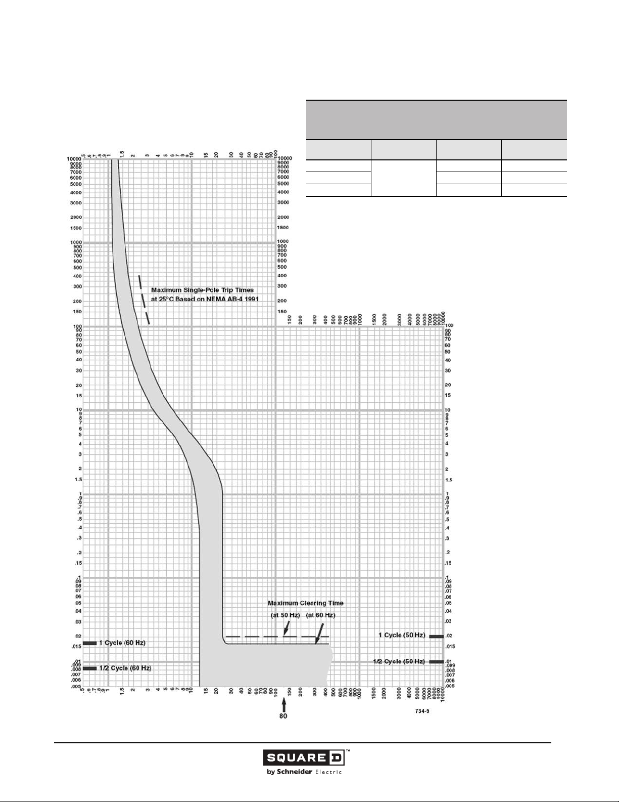
Legacy Thermal-Magnetic / Magnetic Only Molded Case Circuit Breakers
MULTIPLES OF RATED CURRENT
POWERPACT® Q-FRAME MOLDED CASE CIRCUIT BREAKERS
CHARACTERISTIC TRIP CURVE NO. 734-5
CIRCUIT BREAKER INFORMATION
Circuit Breaker
Prefix
QB, QD, QG, QJ
QB, QD, QG 240 3
QJ 208Y/120 3
This curve is to be used for application and coordination purposes only.
The EZ-AMP overlay feature at the bottom of the page should be used during
coordination studies.
All time/current characteristic curve data is based on 104 °F (40 °C) ambient cold
start. Terminations are made with conductors of appropriate length and ratings.
Continuous
Ampere Rating
80
Maximum AC
Voltage
240 2
Number of Poles
TIME IN SECONDS
TIME IN SECONDS
Tripping curves for
coordination studies are
available upon request.
MULTIPLES OF RATED CURRENT
© 1991–2015 Schneider Electric
All Rights Reserved
11/2015
58
Page 59
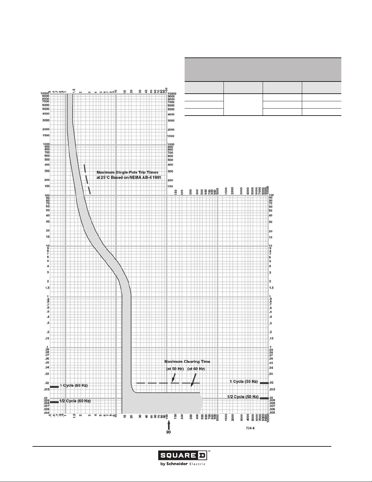
Legacy Thermal-Magnetic / Magnetic Only Molded Case Circuit Breakers
MULTIPLES OF RATED CURRENT
POWERPACT® Q-FRAME MOLDED CASE CIRCUIT BREAKERS
CHARACTERISTIC TRIP CURVE NO. 734-6
CIRCUIT BREAKER INFORMATION
Circuit Breaker
Prefix
QB, QD, QG, QJ
QB, QD, QG 240 3
QJ 208Y/120 3
This curve is to be used for application and coordination purposes only.
The EZ-AMP overlay feature at the bottom of the page should be used during
coordination studies.
All time/current characteristic curve data is based on 104 °F (40 °C) ambient cold
start. Terminations are made with conductors of appropriate length and ratings.
Continuous
Ampere Rating
90
Maximum AC
Voltage
240 2
Number of Poles
TIME IN SECONDS
MULTIPLES OF RATED CURRENT
TIME IN SECONDS
Tripping curves for
coordination studies are
available upon request.
© 1991–2015 Schneider Electric
All Rights Reserved
11/2015
59
Page 60
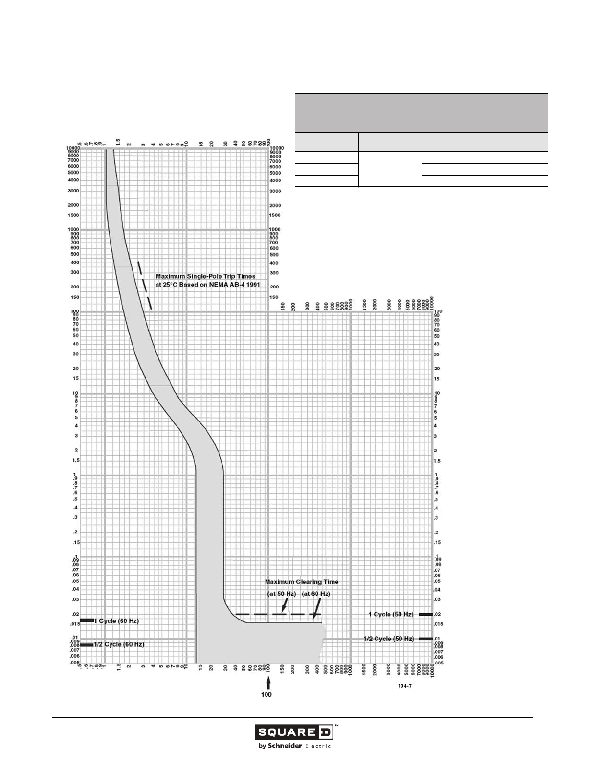
Legacy Thermal-Magnetic / Magnetic Only Molded Case Circuit Breakers
MULTIPLES OF RATED CURRENT
POWERPACT® Q-FRAME MOLDED CASE CIRCUIT BREAKERS
CHARACTERISTIC TRIP CURVE NO. 734-7
CIRCUIT BREAKER INFORMATION
Circuit Breaker
Prefix
QB, QD, QG, QJ
QB, QD, QG 240 3
QJ 208Y/120 3
This curve is to be used for application and coordination purposes only.
The EZ-AMP overlay feature at the bottom of the page should be used during
coordination studies.
All time/current characteristic curve data is based on 104 °F (40 °C) ambient cold
start. Terminations are made with conductors of appropriate length and ratings.
Continuous
Ampere Rating
100
Maximum AC
Voltage
240 2
Number of Poles
TIME IN SECONDS
TIME IN SECONDS
Tripping curves for
coordination studies are
available upon request.
MULTIPLES OF RATED CURRENT
© 1991–2015 Schneider Electric
All Rights Reserved
11/2015
60
Page 61
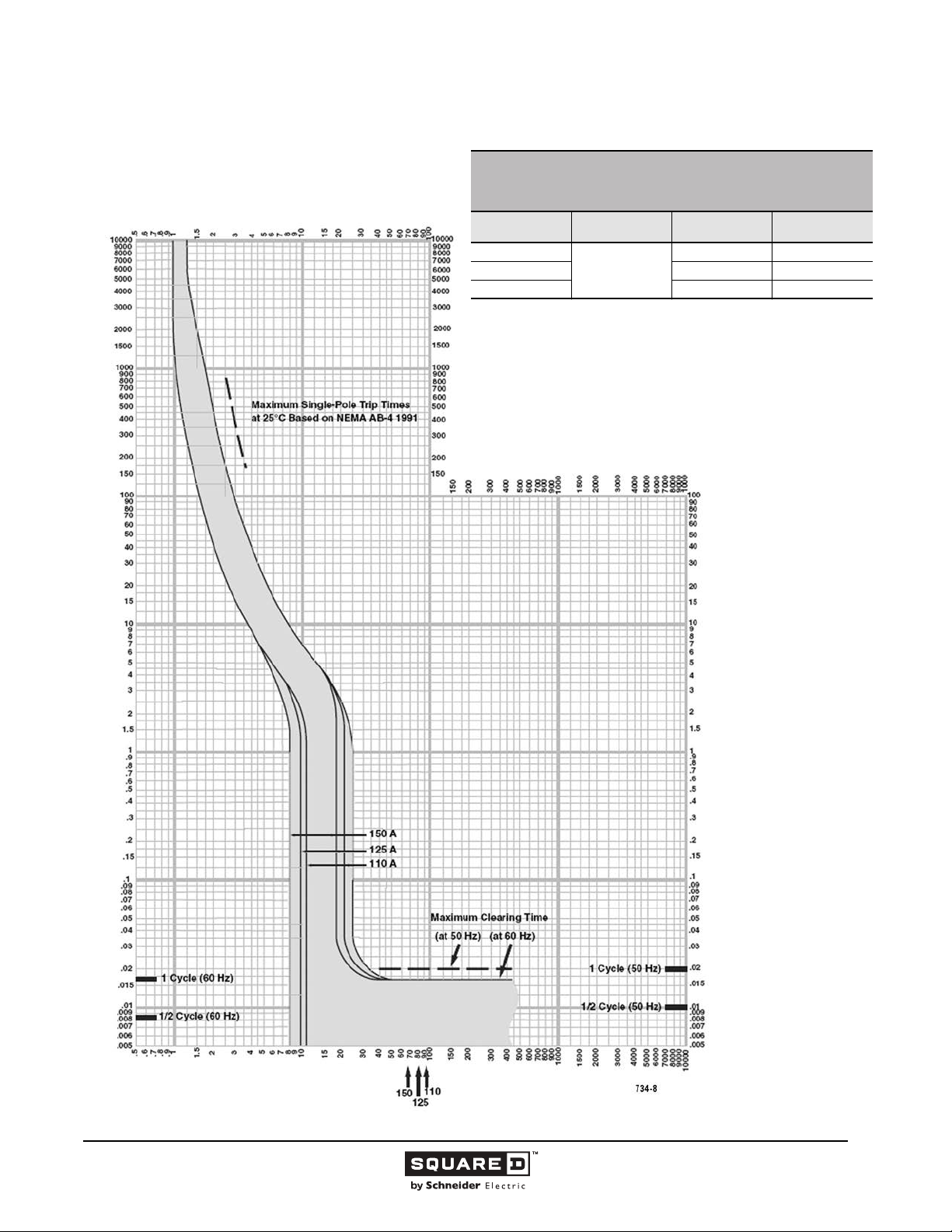
Legacy Thermal-Magnetic / Magnetic Only Molded Case Circuit Breakers
MULTIPLES OF RATED CURRENT
POWERPACT® Q-FRAME MOLDED CASE CIRCUIT BREAKERS
CHARACTERISTIC TRIP CURVE NO. 734-8
CIRCUIT BREAKER INFORMATION
Circuit Breaker
Prefix
QB, QD, QG, QJ
QB, QD, QG 240 3
QJ 208Y/120 3
This curve is to be used for application and coordination purposes only.
The EZ-AMP overlay feature at the bottom of the page should be used during
coordination studies.
All time/current characteristic curve data is based on 104 °F (40 °C) ambient cold
start. Terminations are made with conductors of appropriate length and ratings.
Continuous
Ampere Rating
110–150
Maximum AC
Voltage
240 2
Number of Poles
TIME IN SECONDS
TIME IN SECONDS
Tripping curves for
coordination studies are
available upon request.
MULTIPLES OF RATED CURRENT
© 1991–2015 Schneider Electric
All Rights Reserved
11/2015
61
Page 62
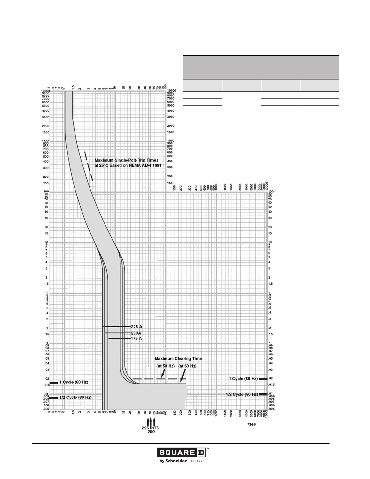
Legacy Thermal-Magnetic / Magnetic Only Molded Case Circuit Breakers
MULTIPLES OF RATED CURRENT
POWERPACT® Q-FRAME MOLDED CASE CIRCUIT BREAKERS
CHARACTERISTIC TRIP CURVE NO. 734-9
CIRCUIT BREAKER INFORMATION
Circuit Breaker
Prefix
QB, QD, QG, QJ
QB, QD, QG 240 3
QJ 208Y/120 3
This curve is to be used for application and coordination purposes only.
The EZ-AMP overlay feature at the bottom of the page should be used during
coordination studies.
All time/current characteristic curve data is based on 104 °F (40 °C) ambient cold
start. Terminations are made with conductors of appropriate length and ratings.
Continuous
Ampere Rating
175–225
Maximum AC
Voltage
240 2
Number of Poles
TIME IN SECONDS
TIME IN SECONDS
Tripping curves for
coordination studies are
available upon request.
MULTIPLES OF RATED CURRENT
© 1991–2015 Schneider Electric
All Rights Reserved
11/2015
62
Page 63
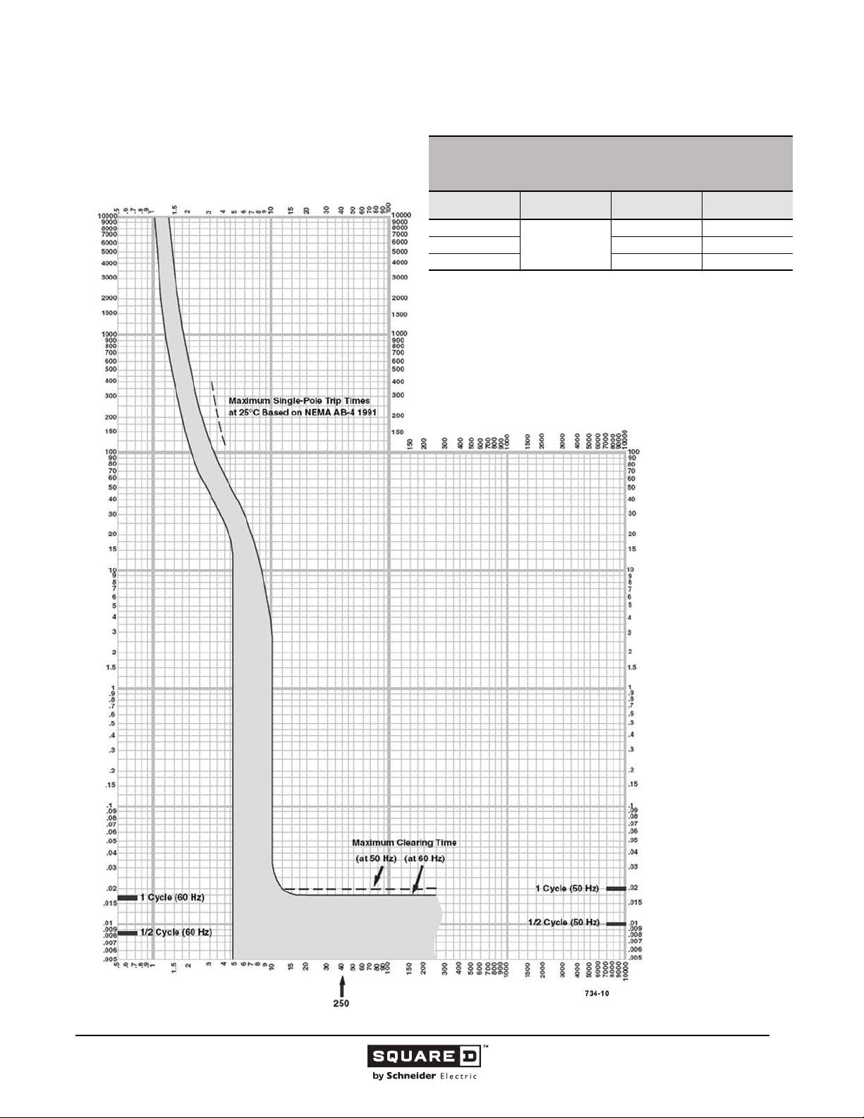
Legacy Thermal-Magnetic / Magnetic Only Molded Case Circuit Breakers
MULTIPLES OF RATED CURRENT
POWERPACT® Q-FRAME MOLDED CASE CIRCUIT BREAKERS
CHARACTERISTIC TRIP CURVE NO. 734-10
CIRCUIT BREAKER INFORMATION
Circuit Breaker
Prefix
QB, QD, QG, QJ
QB, QD, QG 240 3
QJ 208Y/120 3
This curve is to be used for application and coordination purposes only.
The EZ-AMP overlay feature at the bottom of the page should be used during
coordination studies.
All time/current characteristic curve data is based on 104 °F (40 °C) ambient cold
start. Terminations are made with conductors of appropriate length and ratings.
Continuous
Ampere Rating
250
Maximum AC
Voltage
240 2
Number of Poles
TIME IN SECONDS
TIME IN SECONDS
Tripping curves for
coordination studies are
available upon request.
MULTIPLES OF RATED CURRENT
© 1991–2015 Schneider Electric
All Rights Reserved
11/2015
63
Page 64
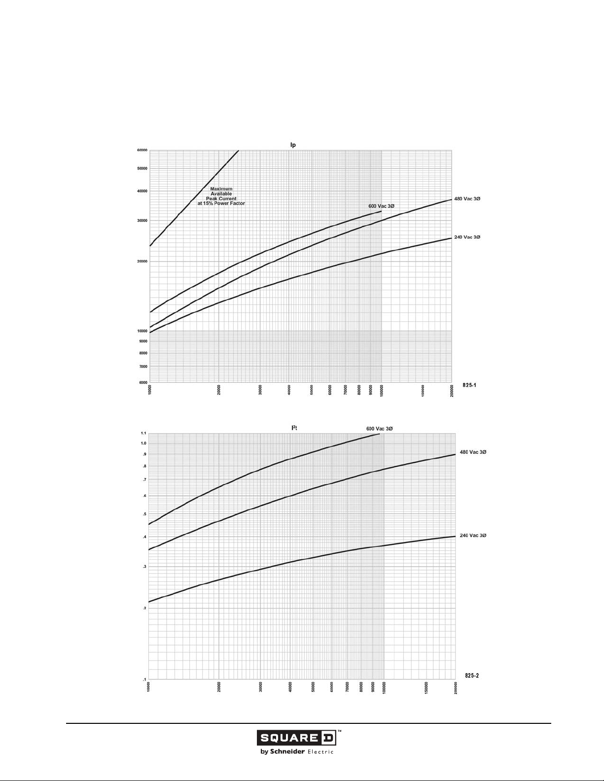
Legacy Thermal-Magnetic / Magnetic Only Molded Case Circuit Breakers
Let-through Curves
KI 250 A Frame at 240, 480 and 600 Vac, 3Ø
110–250 A
Curve No. 825-1 Peak Let-Through Current I
Peak Let-Through Current (Amperes)
H
development and UL test programs.
and 825-2 Let-Through I2t
p
Curve No. 825-1
Maximum
Based on maximum values obtained throughout the circuit breaker
H
)
6
Seconds x 10
2
t (Amperes
2
Let-Through I
development and UL test programs.
H
Curve No. 825-2
Maximum
Based on maximum values obtained throughout the circuit breaker
H
Available Short Circuit Current (RMS Symmetrical Amperes)
Curve No. 0825TC0002
December 2000
64
11/2015 © 1991–2015 Schneider Electric
All Rights Reserved
Page 65
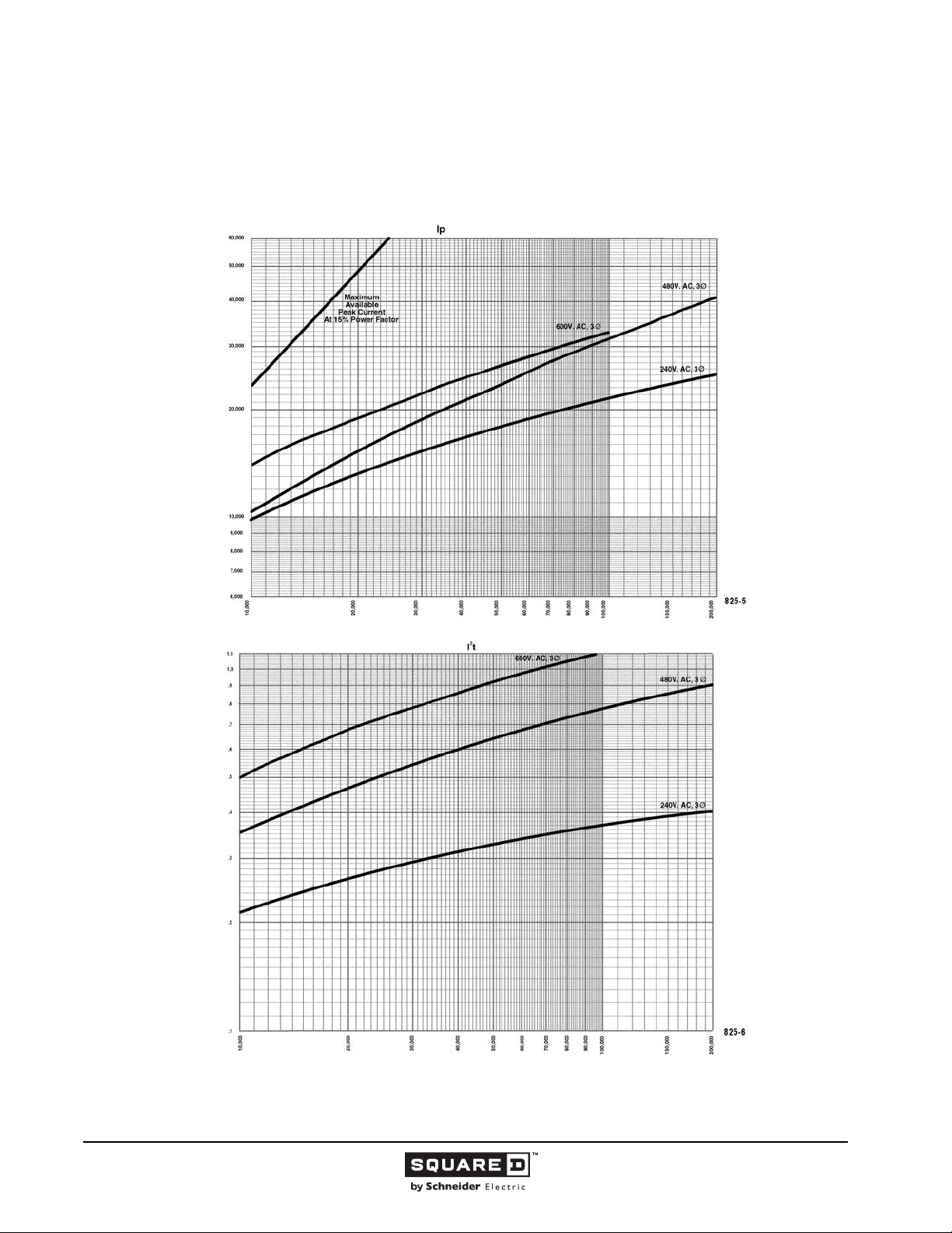
Legacy Thermal-Magnetic / Magnetic Only Molded Case Circuit Breakers
I-LIMITER CURRENT LIMITING CIRCUIT BREAKERS
KI Series 2 250 A Frame at 240, 480 and 600 Vac, 3Ø
Curve No. 825-5 Peak Let-Through Current I
Peak Let-Through Current (Amperes)
H
development and UL test programs.
110–250 A
p
and 825-6 Let-Through I2t
Curve No. 825-5
Maximum
Based on maximum values obtained throughout the circuit breaker
H
Available Short Circuit Current (RMS Symmetrical Amperes)
)
6
Seconds x 10
2
t (Amperes
2
Let-Through I
development and UL test programs.
H
Maximum
Based on maximum values obtained throughout the circuit breaker
H
Curve No. 825-6
Curve No. 0825TC9601
Drawing No. B48095-825-06
© 1991–2015 Schneider Electric
All Rights Reserved
Available Short Circuit Current (RMS Symmetrical Amperes)
65
11/2015
Page 66
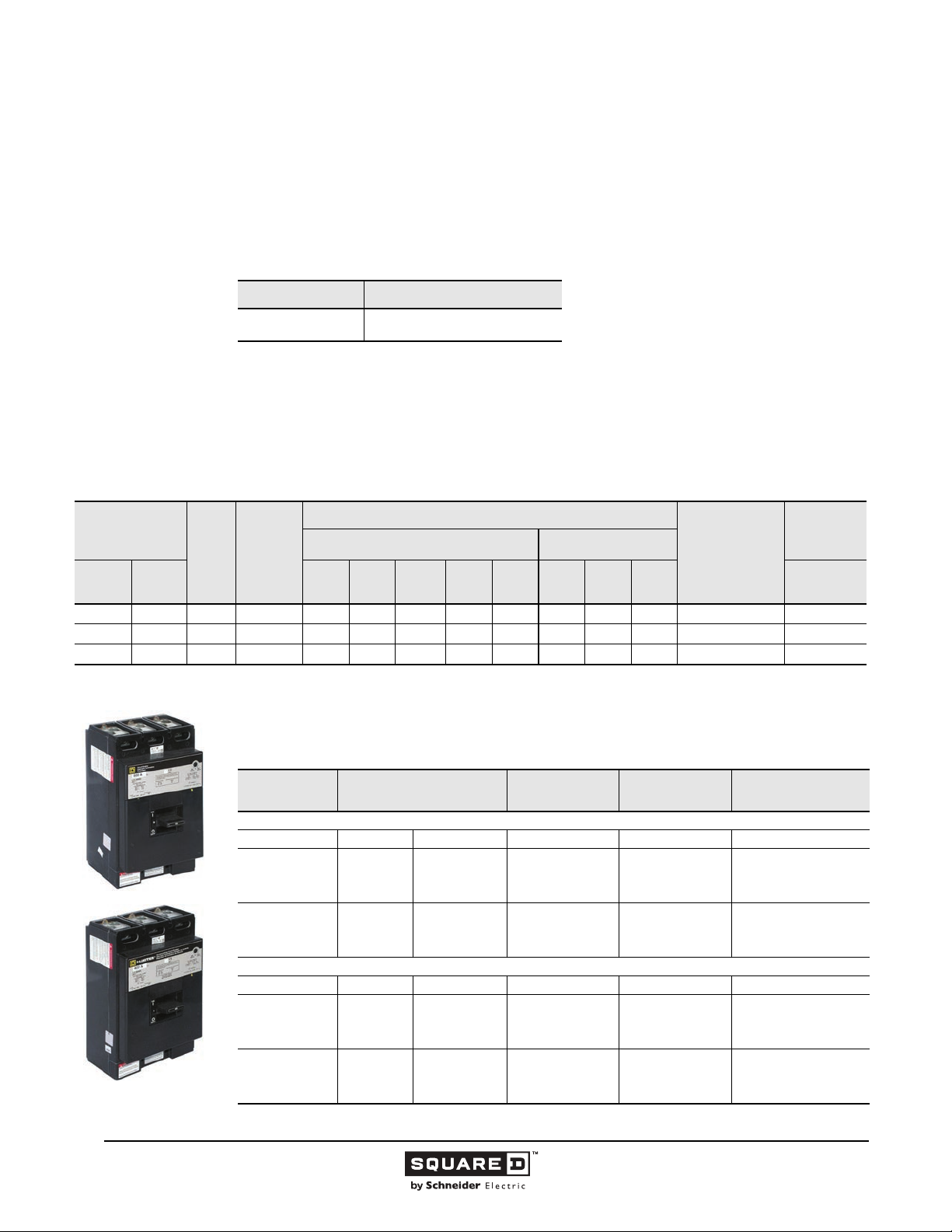
Legacy Thermal-Magnetic / Magnetic Only Molded Case Circuit Breakers
600 Ampere Frame
This section provides specific information on Schneider Electric 600 A frame thermal-magnetic molded
case circuit breakers. For more information, see the “Introduction” in this catalog.
Description
Table 19: Description of 600 A Frame Circuit Breakers
Circuit Breakers Description
LC/LI
Applications
LC and LI circuit breakers are used in industrial enclosures, panelboards, switchboards, busway
plug-in units, combination starters and motor control centers.
.
Table 20: 600 A Frame Interrupting Ratings
300–600 A, 600 Vac, 50/60 Hz, two-
and three-pole
Catalog Number
Prefix
No. of
Poles
Unit
Mount
LCL LC 2, 3 300–400 — 100 — 65 35 — — — 23a 65/65
LCL LC 2, 3 450–600 — 100 — 65 35 — — — 23a 65/50
I-Line 120 240
LIL LI 2, 3 300–600 — 200 — 200 100 — — — 23a —
Cont.
Ampere
Rating
AC Volts - RMS Symmetrical Amperes DC Volts
UL Listed Interrupting Rating (kA)
480Y/
277
480 600 125 250 500 415/240
Federal Specs.
W-C-375B/GEN
IEC 60947-2
Icu/Ics (kA)
AC Voltage
Selection Data
Table 21: 600 A Frame Unit Mount Circuit Breakers
AC Magnetic Trip Settings
Amperes
Low High 600 Vac 600 Vac
1500
1750
2000
2250
2500
3000
Low High 600 Vac/250 Vdc 600 Vac/250 Vdc
1500
1750
2000
2250
2500
3000
1
3200
3200
3200
4200
4200
4200
3200
3200
3200
4200
4200
4200
LCL/LIL
Two- and Three-pole
Ampere Rating
LCL Extra High Interrupting
300
350
400
450
500
600
LIL I-Limiter Current Limiting
300
350
400
450
500
600
1
UL magnetic trip setting tolerances are -20% /+30% (Low) and -20% /+30% (High) from the nominal values shown.
66
11/2015 © 1991–2015 Schneider Electric
Two-Pole
Catalog No.
LCL26300
LCL26350
LCL26400
LCL26450
LCL26500
LCL26600
LIL26300
LIL26350
LIL26400
LIL26450
LIL26500
LIL26600
Three-Pole
Catalog No.
LCL36300
LCL36350
LCL36400
LCL36450
LCL36500
LCL36600
LIL36300
LIL36350
LIL36400
LIL36450
LIL36500
LIL36600
Standard Lug Kit Wire
Range
AL600Li35
2-#1-350 kcmil
AL600LI5
2-4/0-500 kcmil
AL600LI35
2-#1-350 kcmil
AL600LI5
2-4/0-500 kcmil
All Rights Reserved
Page 67
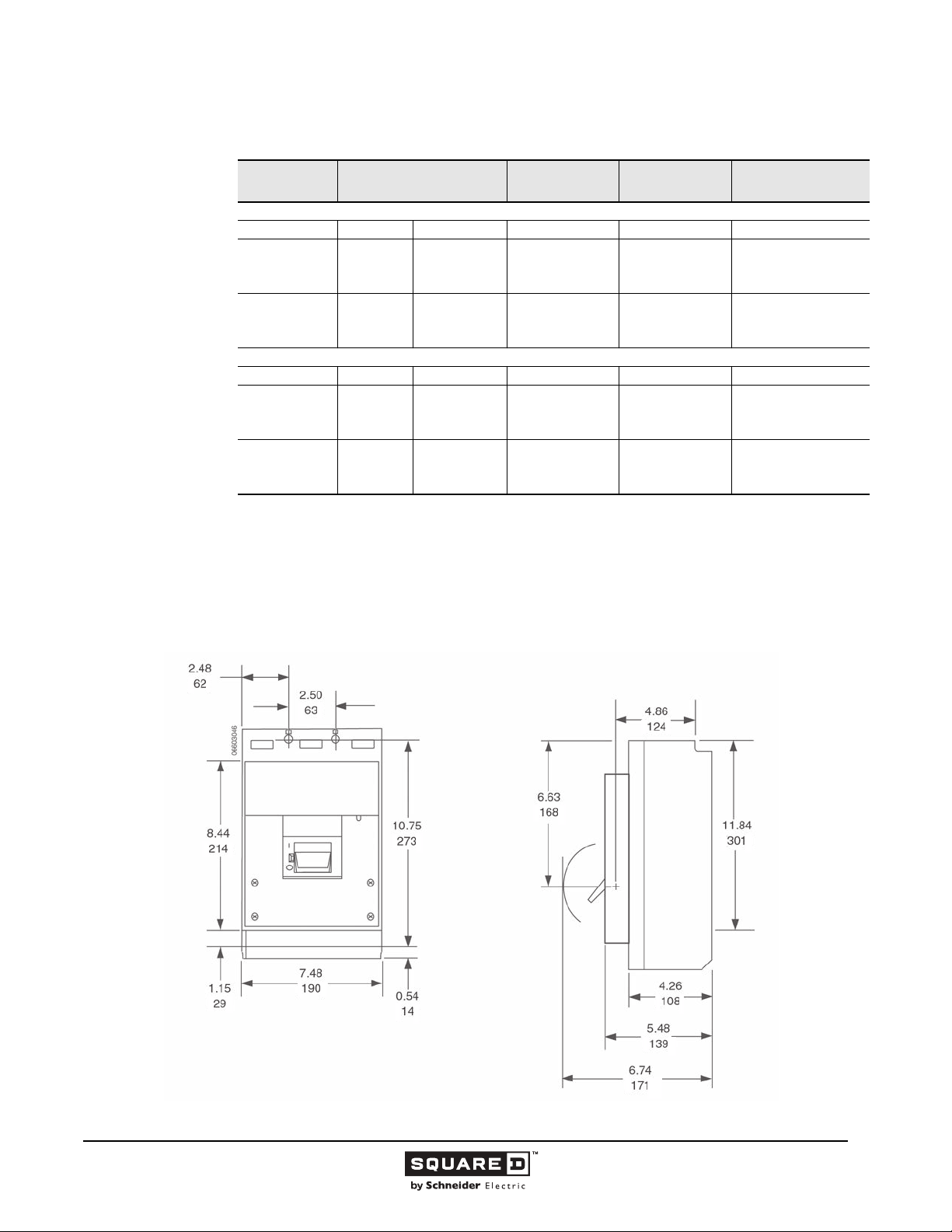
Legacy Thermal-Magnetic / Magnetic Only Molded Case Circuit Breakers
Table 22: 600 A I-Line Mount Circuit Breakers
Ampere Rating
LC Extra High Interrupting
300
350
400
450
500
600
LI I-Limiter Current Limiting
300
350
400
450
500
600
1
Two-pole circuit breaker catalog numbers are completed by adding required phase connection letters as a suffix to the catalog
number.
2
UL magnetic trip setting tolerances are -20% /+30% (Low) and -20% /+30% (High) from the nominal values shown.
AC Magnetic Trip Settings
Amperes
Low High 600 Vac 600 Vac
1500
1750
2000
2250
2500
3000
Low High 600 Vac/250 Vdc 600 Vac/250 Vdc
1500
1750
2000
2250
2500
3000
1
3200
3200
3200
4200
4200
4200
3200
3200
3200
4200
4200
4200
Two-Pole
Catalog No.
LC26300( )
LC26350( )
LC26400( )
LC26450( )
LC26500( )
LC26600( )
li26300( )
li26350( )
li26400( )
LI26450( )
LI26500( )
LI26600( )
2
Three-Pole
Catalog No.
LC36300
LC36350
LC36400
LC36450
LC36500
LC36600
li36300
li36350
li36400
LI36450
LI36500
LI36600
Standard Lug Kit Wire
Range
AL600Li35
2-#1-350 kcmil
AL600LI5
2-4/0-500 kcmil
AL600Li35
2-#1-350 kcmil
AL600LI5
2-4/0-500 kcmil
Dimensions
Figure 14: LCL, LIL 600 A Frame
( )
( )
( )
( )
( )
( )
( )
( )
( )
( )
( )
( )
( )
Dimensions:
in.
(mm)
© 1991–2015 Schneider Electric
All Rights Reserved
11/2015
67
Page 68
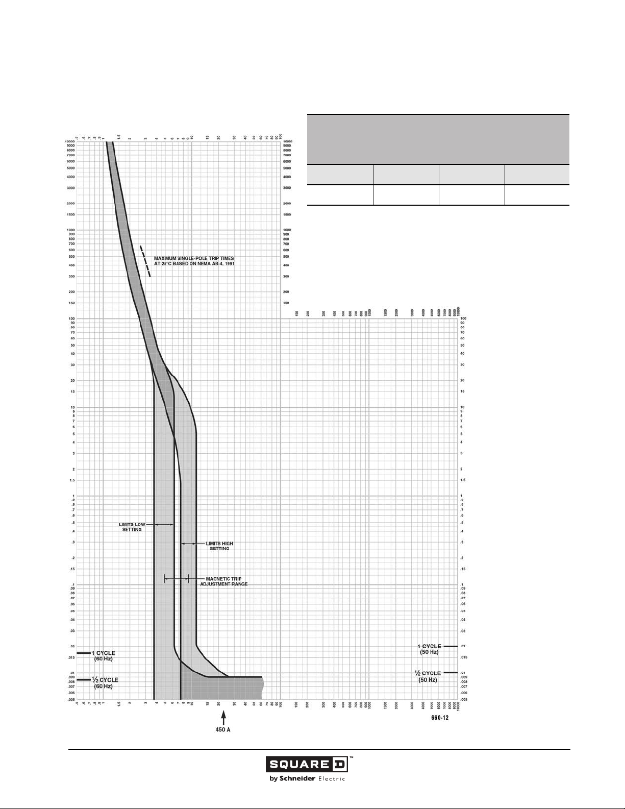
Legacy Thermal-Magnetic / Magnetic Only Molded Case Circuit Breakers
Tripping Curves
MULTIPLES OF RATED CURRENT
LC THERMAL-MAGNETIC MOLDED CASE CIRCUIT BREAKERS
SERIES 3
CHARACTERISTIC TRIP CURVE NO. 660-12
CIRCUIT BREAKER INFORMATION
Circuit Breaker
Prefix
LC 450
This curve is to be used for application and coordination purposes only.
The EZ-AMP overlay feature at the bottom of the page should be used during
coordination studies.
All time/current characteristic curve data is based on 104 °F (40 °C) ambient cold
start. Terminations are made with conductors of appropriate length and ratings.
Continuous
Ampere Rating
Maximum AC
Voltage
240
600
TIME IN SECONDS
Number of Poles
2, 3
TIME IN SECONDS
Tripping curves for
coordination studies are
available upon request.
Curve No. 0660TC0212
March 2002
Drawing No. B48095-660-12
MULTIPLES OF RATED CURRENT
68
11/2015 © 1991–2015 Schneider Electric
All Rights Reserved
Page 69
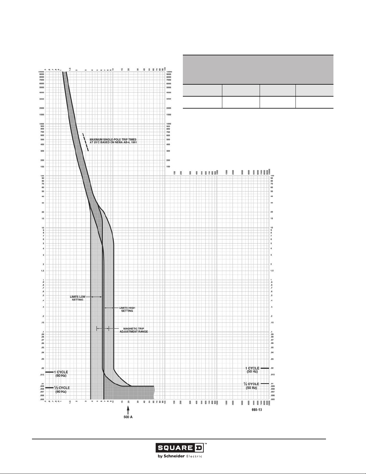
Legacy Thermal-Magnetic / Magnetic Only Molded Case Circuit Breakers
MULTIPLES OF RATED CURRENT
LC THERMAL-MAGNETIC MOLDED CASE CIRCUIT BREAKERS
SERIES 3
CHARACTERISTIC TRIP CURVE NO. 660-13
CIRCUIT BREAKER INFORMATION
Circuit Breaker
Prefix
LC 500
This curve is to be used for application and coordination purposes only.
The EZ-AMP overlay feature at the bottom of the page should be used during
coordination studies.
All time/current characteristic curve data is based on 104 °F (40 °C) ambient cold
start. Terminations are made with conductors of appropriate length and ratings.
Continuous
Ampere Rating
Maximum AC
Voltage
240
600
TIME IN SECONDS
Number of Poles
2, 3
TIME IN SECONDS
MULTIPLES OF RATED CURRENT
Tripping curves for
coordination studies are
available upon request.
Curve No. 0660TC0213
March 2002
Drawing No. B48095-660-13
© 1991–2015 Schneider Electric
All Rights Reserved
11/2015
69
Page 70
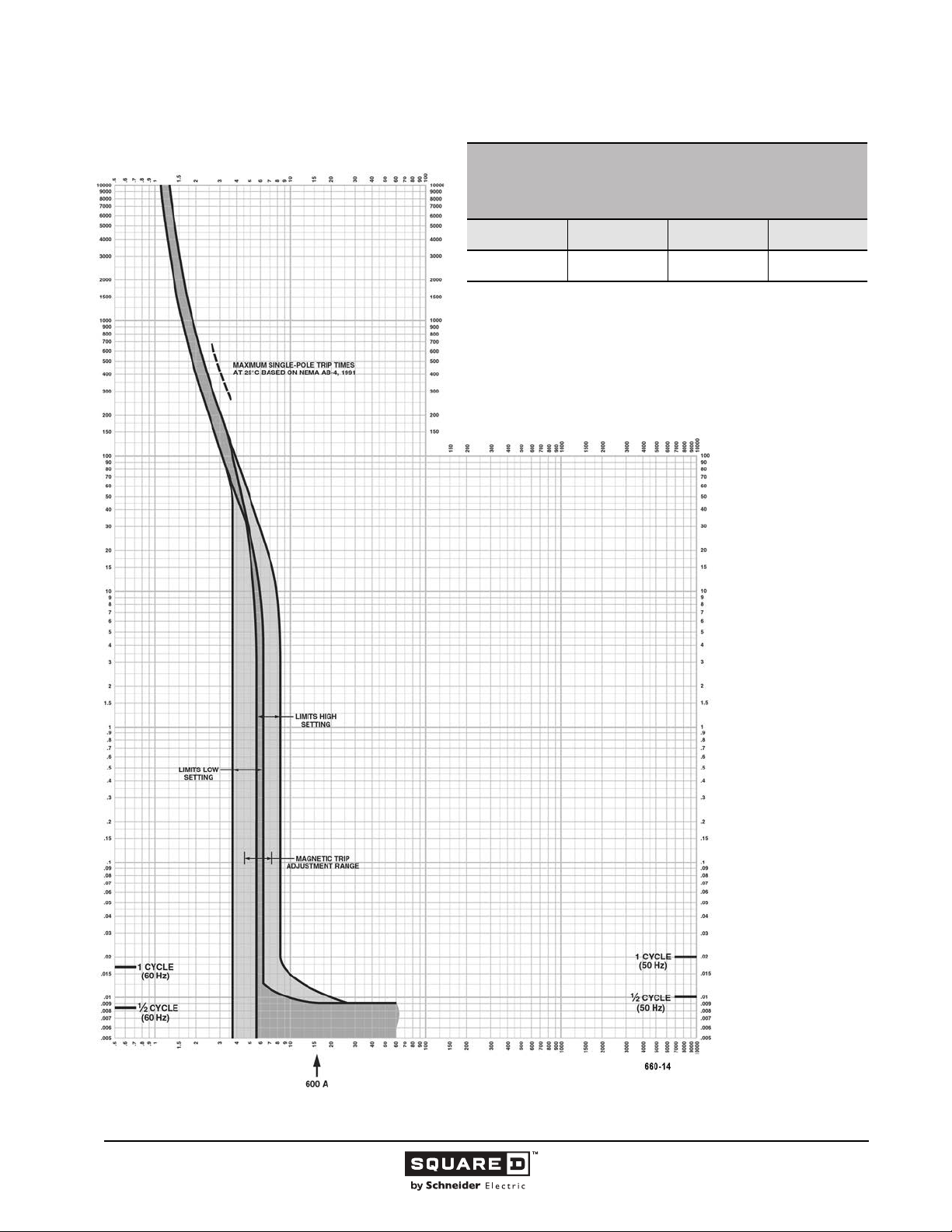
Legacy Thermal-Magnetic / Magnetic Only Molded Case Circuit Breakers
MULTIPLES OF RATED CURRENT
LC THERMAL-MAGNETIC MOLDED CASE CIRCUIT BREAKERS
SERIES 3
CHARACTERISTIC TRIP CURVE NO. 660-14
CIRCUIT BREAKER INFORMATION
Circuit Breaker
Prefix
LC 600
This curve is to be used for application and coordination purposes only.
The EZ-AMP overlay feature at the bottom of the page should be used during
coordination studies.
All time/current characteristic curve data is based on 104 °F (40 °C) ambient cold
start. Terminations are made with conductors of appropriate length and ratings.
Continuous
Ampere Rating
Maximum AC
Voltage
240
600
TIME IN SECONDS
Number of Poles
2, 3
TIME IN SECONDS
MULTIPLES OF RATED CURRENT
Tripping curves for
coordination studies are
available upon request.
Curve No. 0660TC0214
March 2002
Drawing No. B48095-660-14
70
11/2015 © 1991–2015 Schneider Electric
All Rights Reserved
Page 71
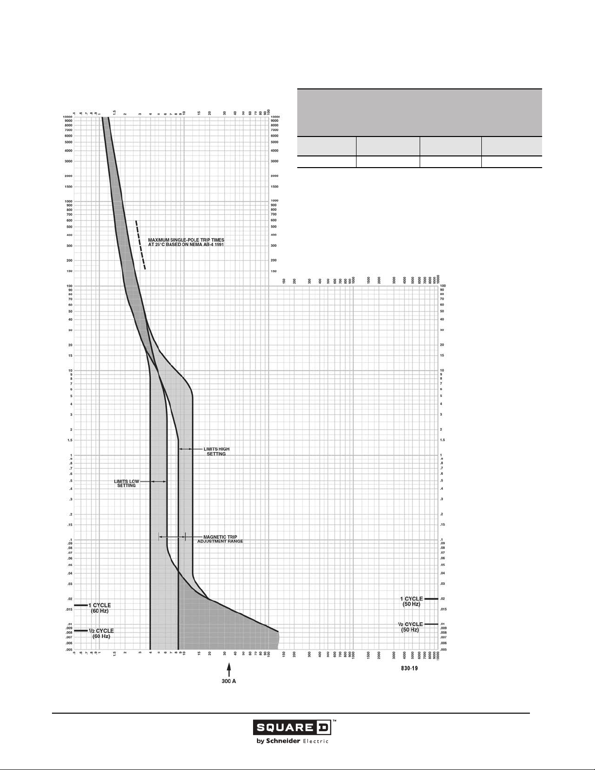
Legacy Thermal-Magnetic / Magnetic Only Molded Case Circuit Breakers
MULTIPLES OF RATED CURRENT
I-LIMITER CURRENT LIMITING CIRCUIT BREAKERS
SERIES 3
CHARACTERISTIC TRIP CURVE NO. 830-19
CIRCUIT BREAKER INFORMATION
Circuit Breaker
Prefix
LI 300 600 2, 3
This curve is to be used for application and coordination purposes only.
The EZ-AMP overlay feature at the bottom of the page should be used during
coordination studies.
All time/current characteristic curve data is based on 104 °F (40 °C) ambient cold
start. Terminations are made with conductors of appropriate length and ratings.
Continuous
Ampere Rating
Maximum AC
Voltage
TIME IN SECONDS
Number of Poles
TIME IN SECONDS
MULTIPLES OF RATED CURRENT
Tripping curves for
coordination studies are
available upon request.
Curve No. 0830TC0219
March 2002
Drawing No. B48095-830-19
© 1991–2015 Schneider Electric
All Rights Reserved
11/2015
71
Page 72
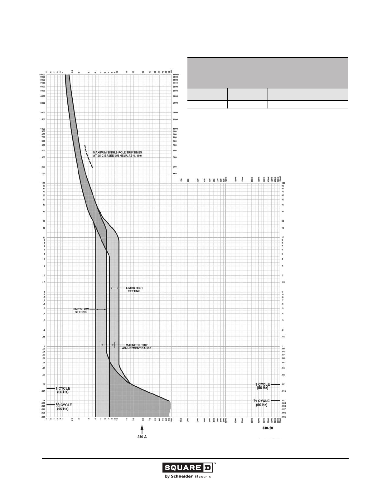
Legacy Thermal-Magnetic / Magnetic Only Molded Case Circuit Breakers
MULTIPLES OF RATED CURRENT
I-LIMITER CURRENT LIMITING CIRCUIT BREAKERS
SERIES 3
CHARACTERISTIC TRIP CURVE NO. 830-20
CIRCUIT BREAKER INFORMATION
Circuit Breaker
Prefix
LI 350 600 2, 3
This curve is to be used for application and coordination purposes only.
The EZ-AMP overlay feature at the bottom of the page should be used during
coordination studies.
All time/current characteristic curve data is based on 104 °F (40 °C) ambient cold
start. Terminations are made with conductors of appropriate length and ratings.
Continuous
Ampere Rating
Maximum AC
Voltage
TIME IN SECONDS
Number of Poles
TIME IN SECONDS
MULTIPLES OF RATED CURRENT
Tripping curves for
coordination studies are
available upon request.
Curve No. 0830TC0220
March 2002
Drawing No. B48095-830-20
72
11/2015 © 1991–2015 Schneider Electric
All Rights Reserved
Page 73
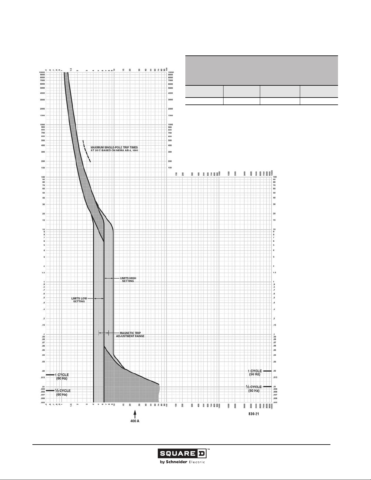
Legacy Thermal-Magnetic / Magnetic Only Molded Case Circuit Breakers
MULTIPLES OF RATED CURRENT
I-LIMITER CURRENT LIMITING CIRCUIT BREAKERS
SERIES 3
CHARACTERISTIC TRIP CURVE NO. 830-21
CIRCUIT BREAKER INFORMATION
Circuit Breaker
Prefix
LI 400 600 2, 3
This curve is to be used for application and coordination purposes only.
The EZ-AMP overlay feature at the bottom of the page should be used during
coordination studies.
All time/current characteristic curve data is based on 104 °F (40 °C) ambient cold
start. Terminations are made with conductors of appropriate length and ratings.
Continuous
Ampere Rating
Maximum AC
Voltage
TIME IN SECONDS
Number of Poles
TIME IN SECONDS
MULTIPLES OF RATED CURRENT
Tripping curves for
coordination studies are
available upon request.
Curve No. 0830TC0221
March 2002
Drawing No. B48095-830-21
© 1991–2015 Schneider Electric
All Rights Reserved
11/2015
73
Page 74
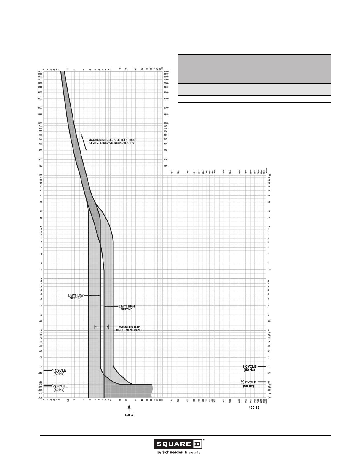
Legacy Thermal-Magnetic / Magnetic Only Molded Case Circuit Breakers
MULTIPLES OF RATED CURRENT
I-LIMITER CURRENT LIMITING CIRCUIT BREAKERS
SERIES 3
CHARACTERISTIC TRIP CURVE NO. 830-22
CIRCUIT BREAKER INFORMATION
Circuit Breaker
Prefix
LI 450 600 2, 3
This curve is to be used for application and coordination purposes only.
The EZ-AMP overlay feature at the bottom of the page should be used during
coordination studies.
All time/current characteristic curve data is based on 104 °F (40 °C) ambient cold
start. Terminations are made with conductors of appropriate length and ratings.
Continuous
Ampere Rating
Maximum AC
Voltage
TIME IN SECONDS
Number of Poles
TIME IN SECONDS
MULTIPLES OF RATED CURRENT
Tripping curves for
coordination studies are
available upon request.
Curve No. 0830TC0222
March 2002
Drawing No. B48095-830-22
74
11/2015 © 1991–2015 Schneider Electric
All Rights Reserved
Page 75
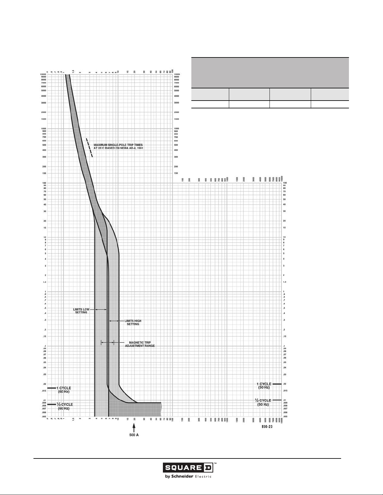
Legacy Thermal-Magnetic / Magnetic Only Molded Case Circuit Breakers
d
MULTIPLES OF RATED CURRENT
I-LIMITER CURRENT LIMITING CIRCUIT BREAKERS
SERIES 3
CHARACTERISTIC TRIP CURVE NO. 830-23
CIRCUIT BREAKER INFORMATION
Circuit Breaker
Prefix
LI 500 600 2, 3
This curve is to be used for application and coordination purposes only.
The EZ-AMP overlay feature at the bottom of the page should be used during
coordination studies.
All time/current characteristic curve data is based on 104 °F (40 °C) ambient col
start. Terminations are made with conductors of appropriate length and ratings.
Continuous
Ampere Rating
Maximum AC
Voltage
TIME IN SECONDS
Number of Poles
TIME IN SECONDS
MULTIPLES OF RATED CURRENT
Tripping curves for
coordination studies are
available upon request.
Curve No. 0830TC0223
March 2002
Drawing No. B48095-830-23
© 1991–2015 Schneider Electric
All Rights Reserved
11/2015
75
Page 76
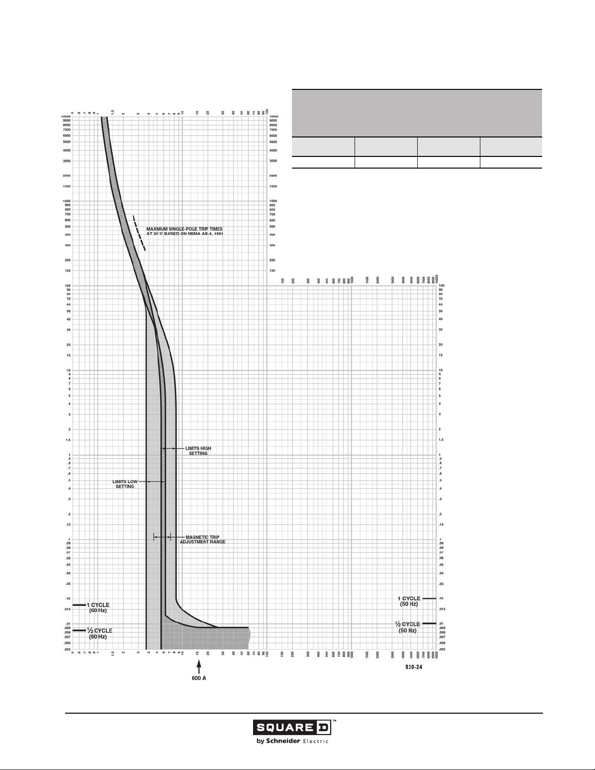
Legacy Thermal-Magnetic / Magnetic Only Molded Case Circuit Breakers
MULTIPLES OF RATED CURRENT
I-LIMITER CURRENT LIMITING CIRCUIT BREAKERS
SERIES 3
CHARACTERISTIC TRIP CURVE NO. 830-24
CIRCUIT BREAKER INFORMATION
Circuit Breaker
Prefix
LI 600 600 2, 3
This curve is to be used for application and coordination purposes only.
The EZ-AMP overlay feature at the bottom of the page should be used during
coordination studies.
All time/current characteristic curve data is based on 104 °F (40 °C) ambient cold
start. Terminations are made with conductors of appropriate length and ratings.
Continuous
Ampere Rating
Maximum AC
Voltage
TIME IN SECONDS
Number of Poles
TIME IN SECONDS
MULTIPLES OF RATED CURRENT
Tripping curves for
coordination studies are
available upon request.
Curve No. 0830TC0224
March 2002
Drawing No. B48095-830-24
76
11/2015 © 1991–2015 Schneider Electric
All Rights Reserved
Page 77
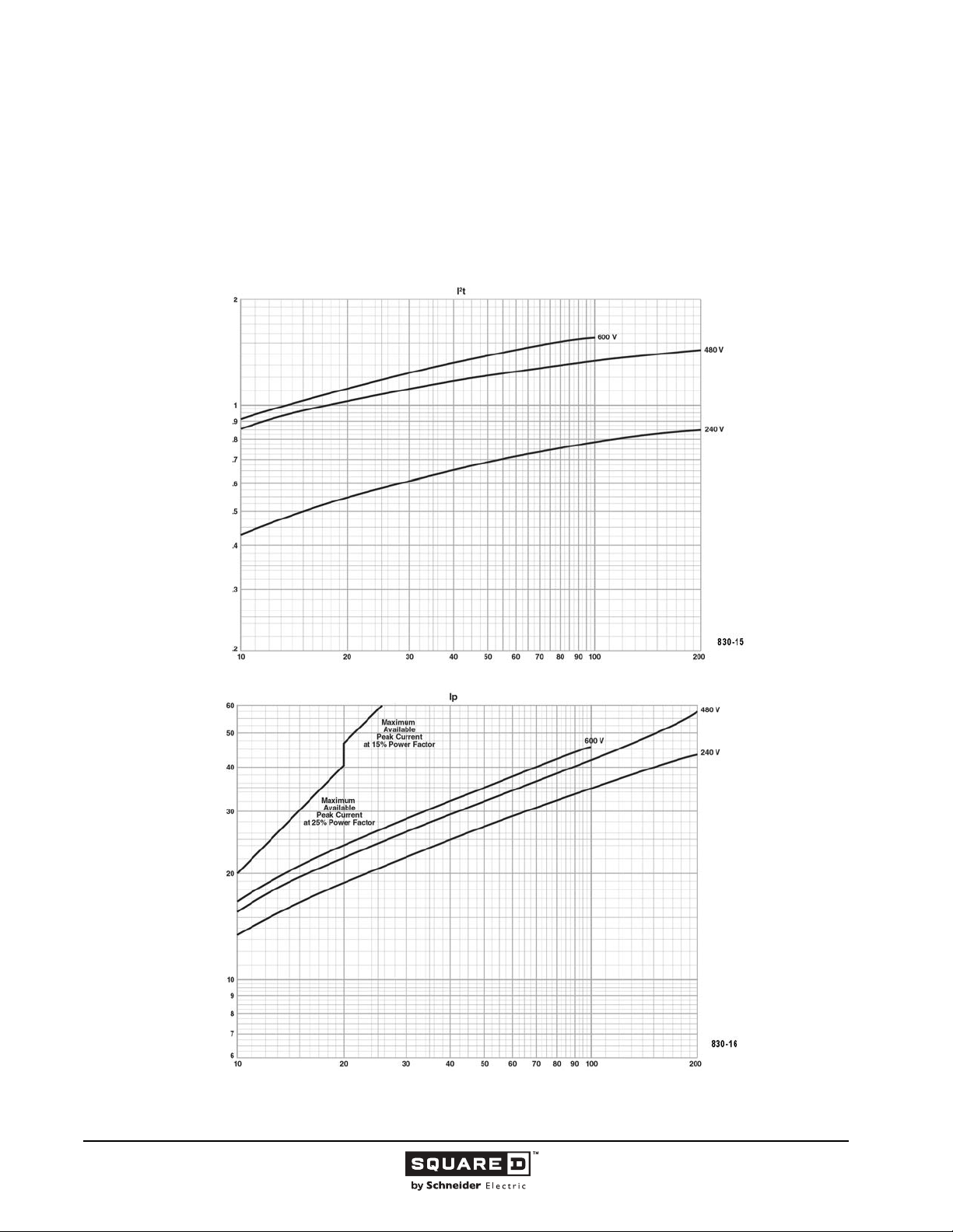
Legacy Thermal-Magnetic / Magnetic Only Molded Case Circuit Breakers
)
6
Seconds x 10
2
t (Amperes
2
Let-through Curves
I-LIMITER CURRENT LIMITING CIRCUIT BREAKERS
LI Series 2, 3 and LXI Series 2B, 3B 400 A Frame at 240, 480 and 600 Vac, 3Ø
300–400 A
LXI Series 2B, 3B 250 A Frame at 240, 480, and 600 Vac, 3Ø
100–250 A
2
Curve No. 830-15 Let-Through I
t and 830-16 Peak Let-Through Current I
Curve No. 830-15
p
development and UL test programs.
Let-Through I
H
Typical
Based on typical values obtained throughout the circuit breaker
H
Available Short Circuit Current (RMS Symmetrical Amperes x 103)
)
3
t (Amperes Seconds x 10
2
Let-Through I
H
development and UL test programs.
Maximum
Based on maximum values obtained throughout the circuit breaker
H
Curve No. 830-16
Curve No. 0830TC0216
March 2002
Drawing No. B48095-830-16
(Replaces No. 0830TC9616)
© 1991–2015 Schneider Electric
All Rights Reserved
Available Short Circuit Current (RMS Symmetrical Amperes x 103)
77
11/2015
Page 78
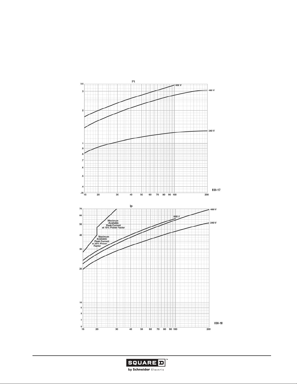
Legacy Thermal-Magnetic / Magnetic Only Molded Case Circuit Breakers
I-LIMITER CURRENT LIMITING CIRCUIT BREAKERS
LI Series 2, 3 and LXI Series 2B, 3B 600 A Frame at 240, 480 and 600 Vac, 3Ø
450–600 A
Curve No. 830-17 Let-Through I2t
)
6
Seconds x 10
2
t (Amperes
2
and 830-18 Peak Let-Through Current I
p
Curve No. 830-17
development and UL test programs.
Let-Through I
H
Typical
Based on typical values obtained throughout the circuit breaker
H
Available Short Circuit Current (RMS Symmetrical Amperes x 103)
)
3
t (Amperes Seconds x 10
2
Let-Through I
H
development and UL test programs.
Maximum
Based on maximum values obtained throughout the circuit breaker
H
Curve No. 830-18
Curve No. 0830TC0218
March 2002
Drawing No. B48095-830-18
(Replaces No. 0830TC9618)
Available Short Circuit Current (RMS Symmetrical Amperes x 103)
78
11/2015 © 1991–2015 Schneider Electric
All Rights Reserved
Page 79
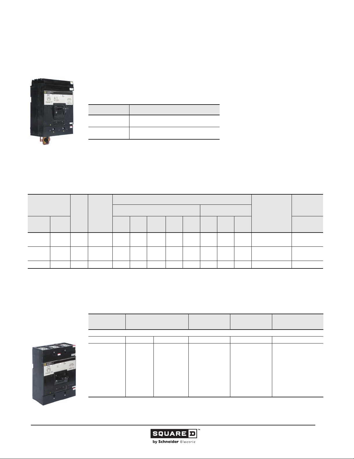
Legacy Thermal-Magnetic / Magnetic Only Molded Case Circuit Breakers
800 / 1000 Ampere Frame
This section provides specific information on Schneider Electric 800 / 1000 A frame thermal-magnetic
molded case circuit breakers. For more information, see the Introduction in this catalog.
Description
Table 23: Description of 800 / 1000 A Frame Circuit Breakers
Circuit Breaker Description
MA/MH
MAL/MHL
300-800 A, 600 Vac, 50/60 Hz, 250 Vdc, two-
and three-pole
300-1200 A, 600 Vac, 50/60 Hz, 250 Vdc, two-
and three-pole
MA/MH
Two- and Three-pole
9” Mounting Height
300–800 A
Applications
MA / MH circuit breakers are used in industrial enclosures, panelboards, switchboards, busway plug-in
units, combination starters and motor control centers.
Table 24: 800 / 1000 A Frame Interrupting Ratings
Catalog Number
Prefix
No. of
Poles
Unit
Mount
MAL
MHL
LHL-DC
1
Separate UL rating available for 240 Vac and 480 Vac grounded B single phase systems. Cirbuit breakers must be ordered with 5861 suffix. See Supplemental
Digest for specific ratings.
2
UL listed 500 Vdc rating for use on ungrounded systems. Must be connected 3 poles in series. Consult the Schneider Electric Customer Care center for additional
information
I-Line 120 240
—
—
—
MA
1
—
MH
2
— 3 — ———————20 — —
2, 3
2, 3
2, 3
1
2, 3
Cont.
Ampere
AC Volts - RMS Symmetrical Amperes DC Volts
Rating
300–1000
300–8004242
300–1000
300–8006565
UL Listed Interrupting Rating (kA)
480Y/
277
42
42
65
65
480 600 125 250 500 415/240
30
30
65
65
30
22
30
22
65
25
65
25
Federal Specs.
W-C-375B/GEN
14
14
14
14
—
—
14
14
—
—
—
—
21a
21a
23a
23a
IEC 60947-2
Icu/Ics (kA)
AC Voltage
30/30
30/30
65/33
65/33
Selection Data
Table 25: 800 A I-Line Circuit Breakers
Ampere Rating
MA Standard Interrupting
1
UL magnetic trip setting tolerances are -20% /+30% (Low) and -20% /+30% (High) from the nominal values shown.
2
Two-pole circuit breaker catalog numbers are completed by adding required phase connection letters as a suffix to the catalog
MAL/MHL
Two- and Three-pole
300–1000 A
number.
© 1991–2015 Schneider Electric
All Rights Reserved
300
350
400
450
500
600
700
800
AC Magnetic Trip Settings
Amperes
Low High 600 Vac/250 Vdc 600 Vac/250 Vdc
1500
1750
2000
2250
2500
3000
3500
4000
1
3000
3500
4000
4500
5000
6000
7000
8000
Two-Pole
Catalog No.
MA26300( )
MA26350( )
MA26400( )
MA26450( )
MA26500( )
MA26600( )
MA26700( )
MA26800( )
2
Three-Pole
Catalog No.
MA36300
MA36350
MA36400
MA36450
MA36500
MA36600
MA36700
MA36800
Standard Lug Kit Wire
Range
AL900MA
3-#3/0-500 kcmil
—Continued on next page
79
11/2015
Page 80
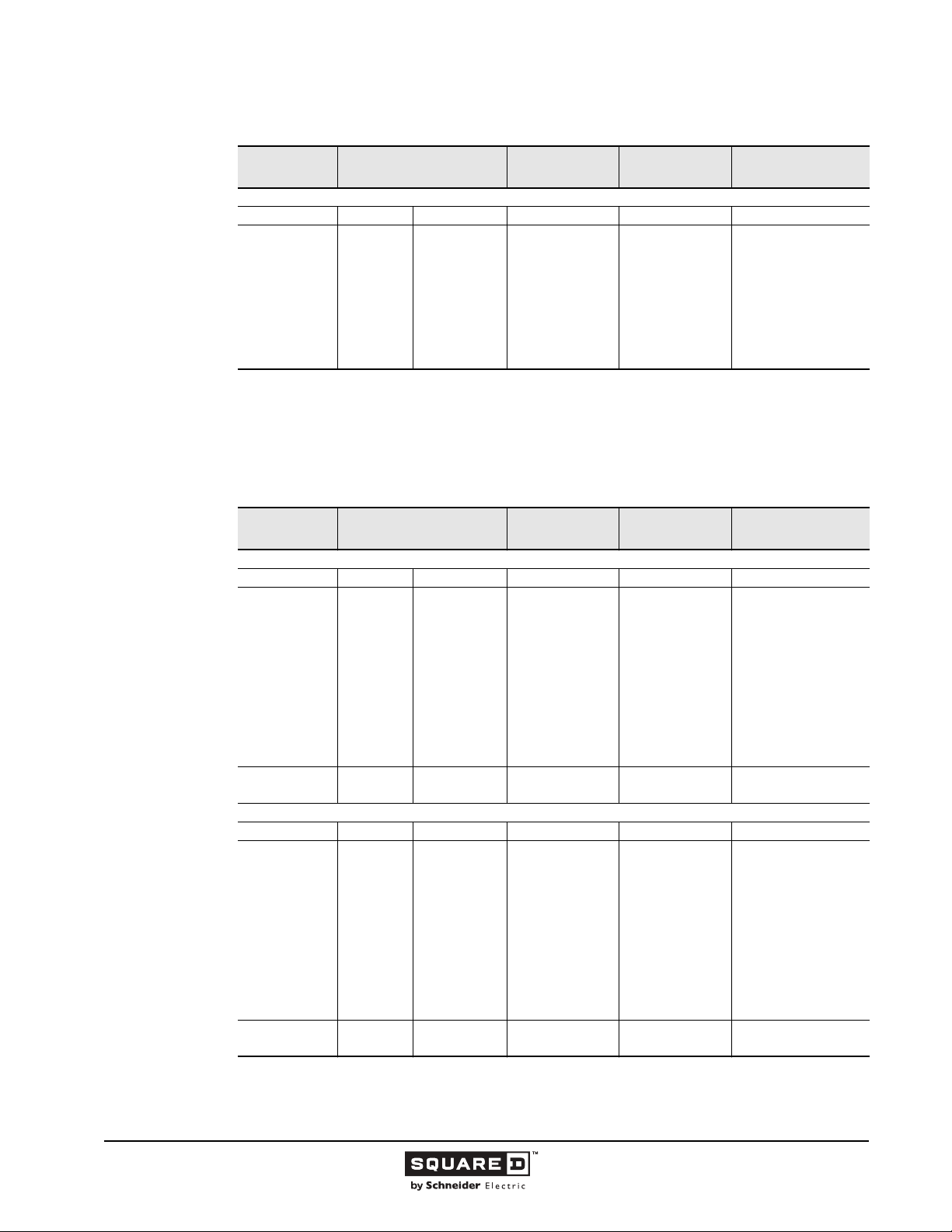
Legacy Thermal-Magnetic / Magnetic Only Molded Case Circuit Breakers
Table 25: 800 A I-Line Circuit Breakers (continued)
Ampere Rating
MH High Interrupting
300
350
400
450
500
600
700
800
1
UL magnetic trip setting tolerances are -20% /+30% (Low) and -20% /+30% (High) from the nominal values shown.
2
Two-pole circuit breaker catalog numbers are completed by adding required phase connection letters as a suffix to the catalog
number.
AC Magnetic Trip Settings
Amperes
Low High 600 Vac/250 Vdc 600 Vac/250 Vdc
1500
1750
2000
2250
2500
3000
3500
4000
1
3000
3500
4000
4500
5000
6000
7000
8000
Two-Pole
Catalog No.
MH26300( )
MH26350( )
MH26400( )
MH26450( )
MH26500( )
MH26600( )
MH26700( )
MH26800( )
2
Three-Pole
Catalog No.
MH36300
MH36350
MH36400
MH36450
MH36500
MH36600
MH36700
MH36800
Standard Lug Kit Wire
Range
AL900MA
3-#3/0-500 kcmil
Table 26: 1000 A Frame Unit Mount Circuit Breakers
Ampere Rating
MAL Standard Interrupting
300
350
400
450
500
600
700
800
900
1000
1200 5100 10200 MHL261200 MHL361200
MHL High Interrupting
300
350
400
450
500
600
700
800
900
1000
1200 5100 10200 MAL261200 MAL361200
1
UL magnetic trip setting tolerances are -20% /+30% (Low) and -20% /+30% (High) from the nominal values shown.
2
Two-pole circuit breaker catalog numbers are completed by adding required phase connection letters as a suffix to the catalog
number.
AC Magnetic Trip Settings
Amperes
Low High 600 Vac/250 Vdc 600 Vac/250 Vdc
1500
1750
2000
2250
2500
3000
3500
4000
4500
5000
Low High 600 Vac/250 Vdc 600 Vac/250 Vdc
1500
1750
2000
2250
2500
3000
3500
4000
4500
5000
1
3000
3500
4000
4500
5000
6000
7000
8000
9000
10000
3000
3500
4000
4500
5000
6000
7000
8000
9000
10000
Two-Pole
Catalog No.
MAL26300
MAL26350
MAL26400
MAL26450
MAL26500
MAL26600
MAL26700
MAL26800
MAL26900
MAL261000
MHL26300
MHL26350
MHL26400
MHL26450
MHL26500
MHL26600
MHL26700
MHL26800
MHL26900
MHL261000
2
Three-Pole
Catalog No.
MAL36300
MAL36350
MAL36400
MAL36450
MAL36500
MAL36600
MAL36700
MAL36800
MAL36900
MAL361000
MHL36300
MHL36350
MHL36400
MHL36450
MHL36500
MHL36600
MHL36700
MHL36800
MHL36900
MHL361000
Standard Lug Kit Wire
Range
AL900MA
3-#3/0-350 kcmil
AL1000MA
4-#1/0-500 kcmil
AL900MA
3-#3/0-500 kcmil
AL1000MA
4-#1/0-350 kcmil
80
11/2015 © 1991–2015 Schneider Electric
All Rights Reserved
Page 81
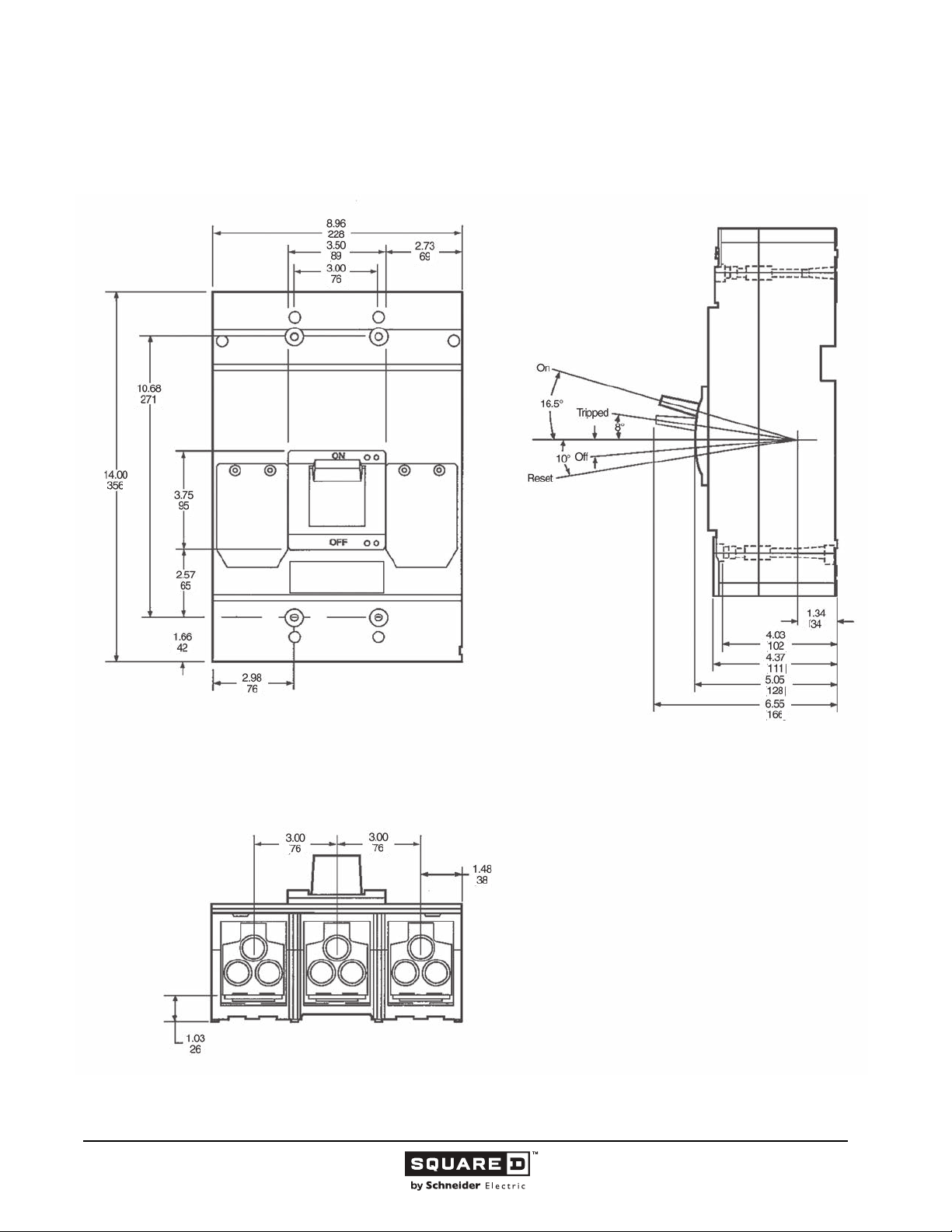
Legacy Thermal-Magnetic / Magnetic Only Molded Case Circuit Breakers
Dimensions
Figure 15: MAL, MHL 800 / 1000 A Frame
( )
( )
( )
( )
( )
( )
( )
( )
( )
( )
( )
( )
( )
( )
( )
( )
( )
( )
( )
( )
( )
( )
( )
Dimensions:
in.
(mm)
© 1991–2015 Schneider Electric
All Rights Reserved
11/2015
81
Page 82
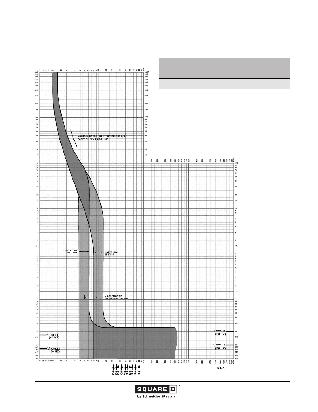
Legacy Thermal-Magnetic / Magnetic Only Molded Case Circuit Breakers
Tripping Curves
MULTIPLES OF RATED CURRENT
MA/MH FAMILY MOLDED CASE CIRCUIT BREAKERS
CHARACTERISTIC TRIP CURVE NO. 665-1
CIRCUIT BREAKER INFORMATION
Circuit Breaker
Prefix
MA/MH 125–450 600 2, 3
This curve is to be used for application and coordination purposes only.
The EZ-AMP overlay feature at the bottom of the page should be used during
coordination studies.
All time/current characteristic curve data is based on 104 °F (40 °C) ambient cold
start. Terminations are made with conductors of appropriate length and ratings.
Continuous
Ampere Rating
Maximum AC
Voltage
TIME IN SECONDS
Number of Poles
TIME IN SECONDS
Tripping curves for
coordination studies are
available upon request.
Curve No. 0665TC8501
Drawing No. B48095-665-01
MULTIPLES OF RATED CURRENT
82
11/2015 © 1991–2015 Schneider Electric
All Rights Reserved
Page 83
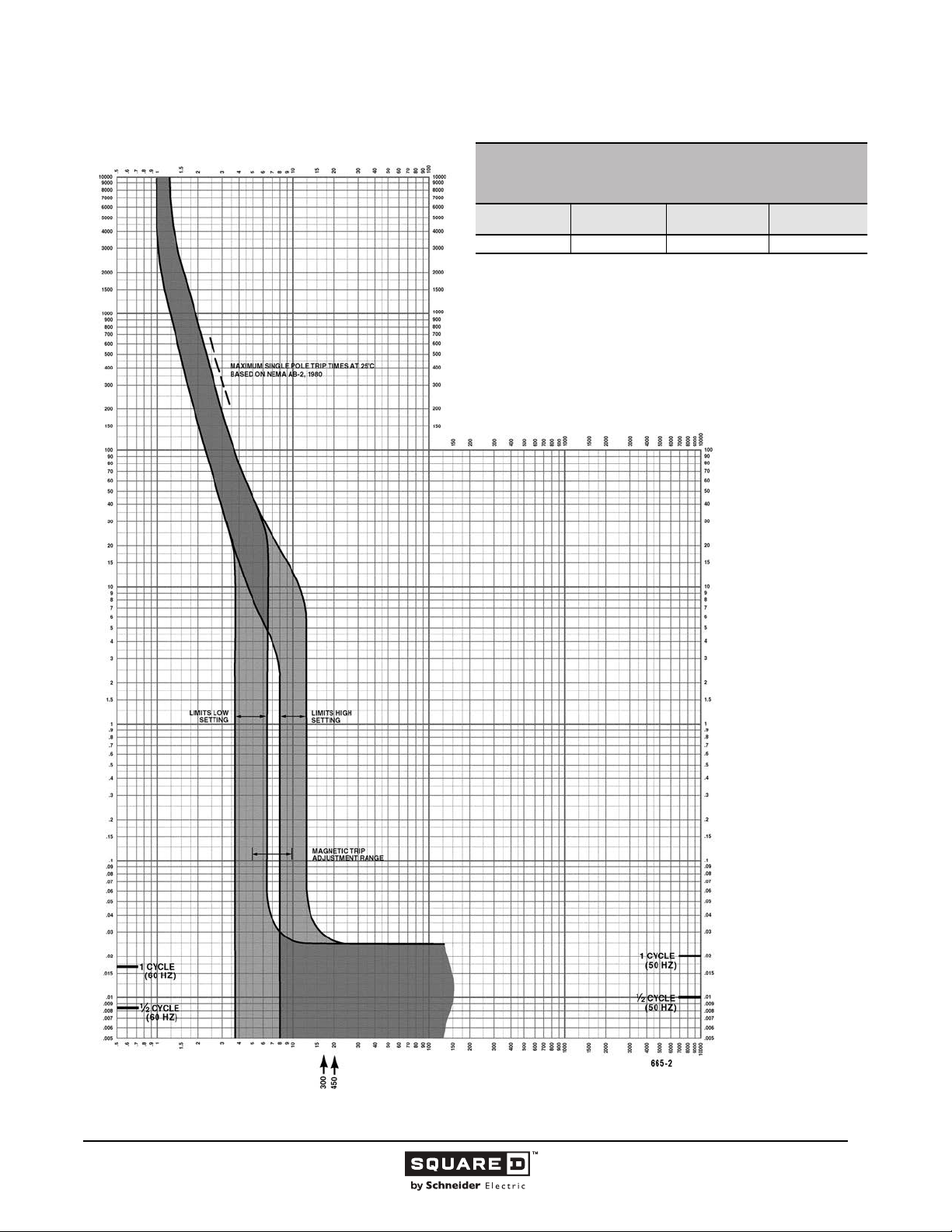
Legacy Thermal-Magnetic / Magnetic Only Molded Case Circuit Breakers
MULTIPLES OF RATED CURRENT
MA/MH FAMILY MOLDED CASE CIRCUIT BREAKERS
CHARACTERISTIC TRIP CURVE NO. 665-2
CIRCUIT BREAKER INFORMATION
Circuit Breaker
Prefix
MA/MH 500–600 600 2, 3
This curve is to be used for application and coordination purposes only.
The EZ-AMP overlay feature at the bottom of the page should be used during
coordination studies.
All time/current characteristic curve data is based on 104 °F (40 °C) ambient cold
start. Terminations are made with conductors of appropriate length and ratings.
Continuous
Ampere Rating
Maximum AC
Voltage
TIME IN SECONDS
Number of Poles
TIME IN SECONDS
MULTIPLES OF RATED CURRENT
Tripping curves for
coordination studies are
available upon request.
Curve No. 0665TC8502
Drawing No. B48095-665-02
© 1991–2015 Schneider Electric
All Rights Reserved
11/2015
83
Page 84
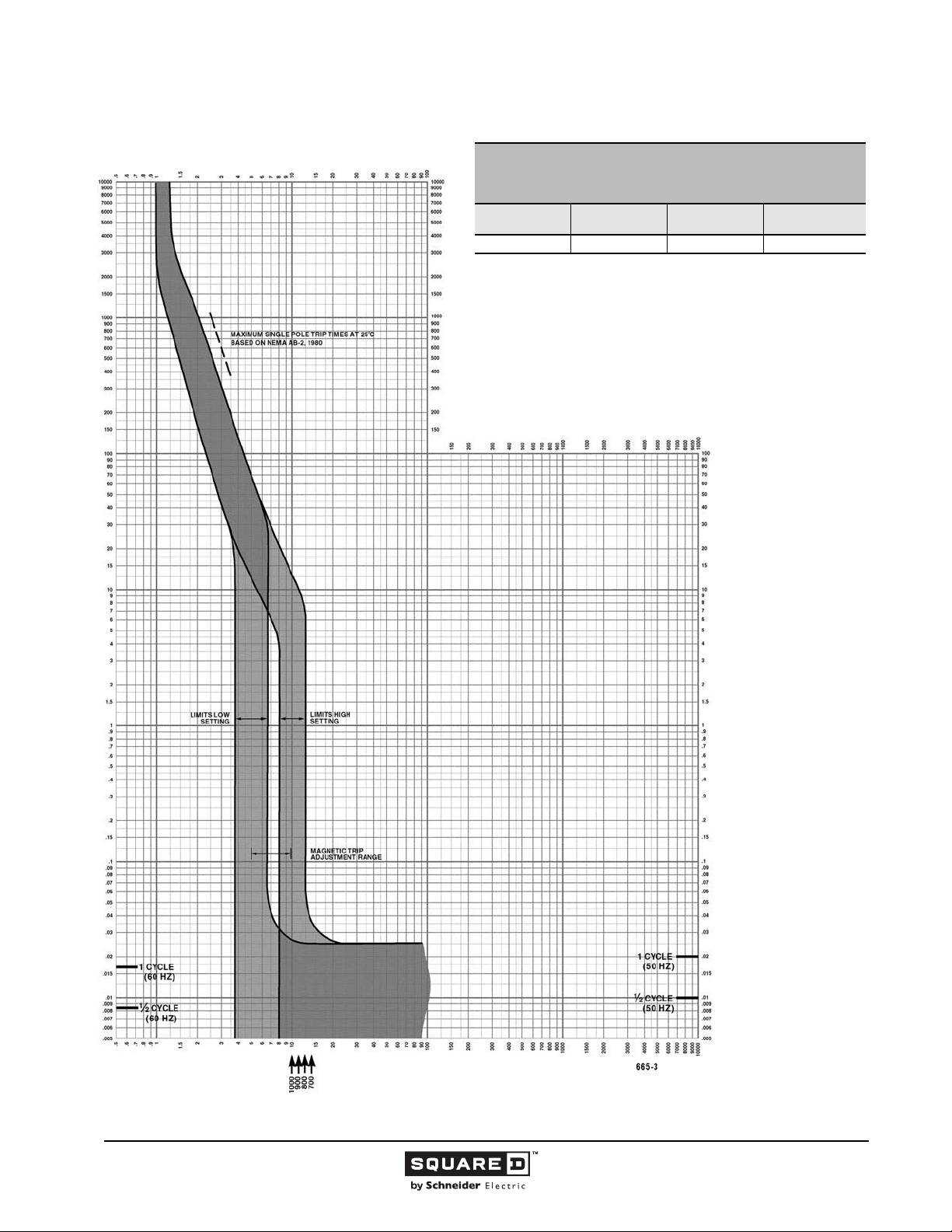
Legacy Thermal-Magnetic / Magnetic Only Molded Case Circuit Breakers
MULTIPLES OF RATED CURRENT
MA/MH FAMILY MOLDED CASE CIRCUIT BREAKERS
CHARACTERISTIC TRIP CURVE NO. 665-3
CIRCUIT BREAKER INFORMATION
Circuit Breaker
Prefix
MA/MH 700–1000 600 2, 3
This curve is to be used for application and coordination purposes only.
The EZ-AMP overlay feature at the bottom of the page should be used during
coordination studies.
All time/current characteristic curve data is based on 104 °F (40 °C) ambient
cold start. Terminations are made with conductors of appropriate length and
ratings.
Continuous
Ampere Rating
Maximum AC
Voltage
TIME IN SECONDS
Number of Poles
TIME IN SECONDS
Tripping curves for
coordination studies are
available upon request.
Curve No. 0665TC8503
Drawing No. B48095-665-03
MULTIPLES OF RATED CURRENT
84
11/2015 © 1991–2015 Schneider Electric
All Rights Reserved
Page 85
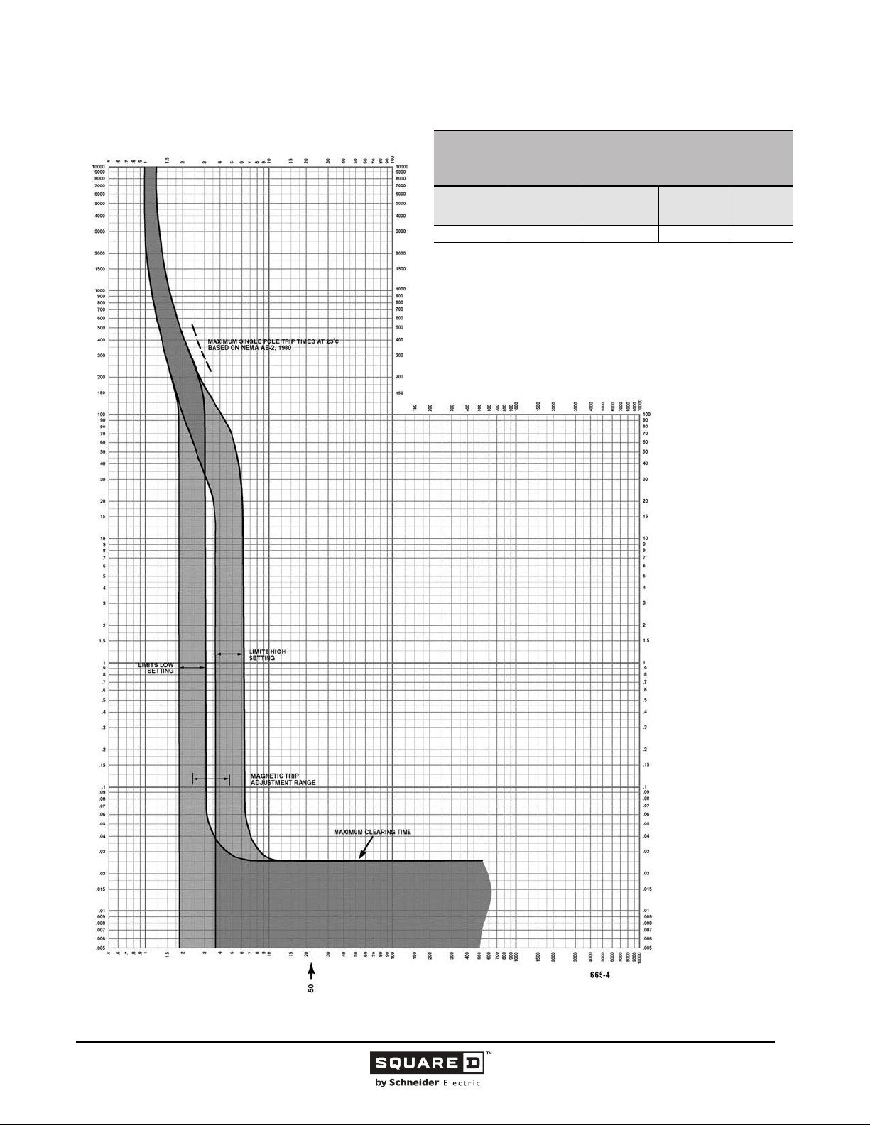
Legacy Thermal-Magnetic / Magnetic Only Molded Case Circuit Breakers
MULTIPLES OF RATED CURRENT
MH FAMILY MOLDED CASE CIRCUIT BREAKERS
CHARACTERISTIC TRIP CURVE NO. 665-4
CIRCUIT BREAKER INFORMATION
Circuit
Breaker Prefix
MH 31DC 450 500 3
This curve is to be used for application and coordination purposes only.
The EZ-AMP overlay feature at the bottom of the page should be used during
coordination studies.
All time/current characteristic curve data is based on 104 °F (40 °C) ambient cold
start. Terminations are made with conductors of appropriate length and ratings.
Circuit
Breaker Suffix
Continuous
Ampere
Rating
Maximum DC
Voltage
TIME IN SECONDS
Number of
Poles
TIME IN SECONDS
MULTIPLES OF RATED CURRENT
Tripping curves for
coordination studies are
available upon request.
Curve No. 0665TC8504
Drawing No. B48095-665-04
© 1991–2015 Schneider Electric
All Rights Reserved
11/2015
85
Page 86
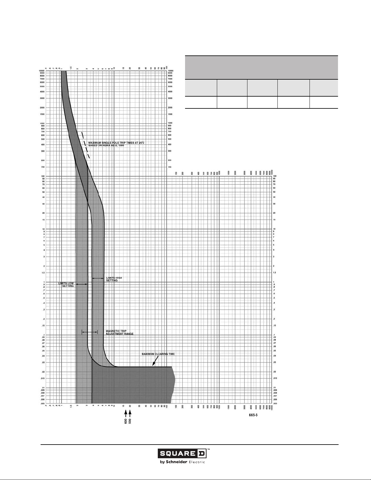
Legacy Thermal-Magnetic / Magnetic Only Molded Case Circuit Breakers
MULTIPLES OF RATED CURRENT
MH FAMILY MOLDED CASE CIRCUIT BREAKERS
CHARACTERISTIC TRIP CURVE NO. 665-5
CIRCUIT BREAKER INFORMATION
Circuit
Breaker Prefix
MH
This curve is to be used for application and coordination purposes only.
The EZ-AMP overlay feature at the bottom of the page should be used during
coordination studies.
All time/current characteristic curve data is based on 104 °F (40 °C) ambient cold
start. Terminations are made with conductors of appropriate length and ratings.
Circuit
Breaker
Suffix
32DC
33DC
Continuous
Ampere
Rating
500
600
Maximum DC
Voltage
500 3
TIME IN SECONDS
Number of
Poles
TIME IN SECONDS
Tripping curves for
coordination studies are
available upon request.
Curve No. 0665TC8505
Drawing No. B48095-665-05
MULTIPLES OF RATED CURRENT
86
11/2015 © 1991–2015 Schneider Electric
All Rights Reserved
Page 87
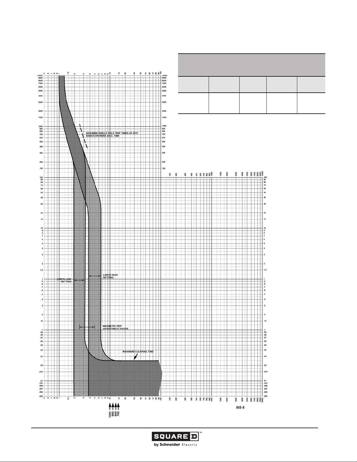
Legacy Thermal-Magnetic / Magnetic Only Molded Case Circuit Breakers
MULTIPLES OF RATED CURRENT
MH FAMILY MOLDED CASE CIRCUIT BREAKERS
CHARACTERISTIC TRIP CURVE NO. 665-6
CIRCUIT BREAKER INFORMATION
Circuit
Breaker Prefix
MH
This curve is to be used for application and coordination purposes only.
The EZ-AMP overlay feature at the bottom of the page should be used during
coordination studies.
All time/current characteristic curve data is based on 104 °F (40 °C) ambient cold
start. Terminations are made with conductors of appropriate length and ratings.
Circuit
Breaker Suffix
35DC
36DC
39DC
40DC
Continuous
Ampere
Rating
700
800
900
1000
Maximum DC
Voltage
500 3
TIME IN SECONDS
Number of
Poles
TIME IN SECONDS
Tripping curves for
coordination studies are
available upon request.
Curve No. 665-6
May 1989
MULTIPLES OF RATED CURRENT
© 1991–2015 Schneider Electric
All Rights Reserved
11/2015
87
Page 88
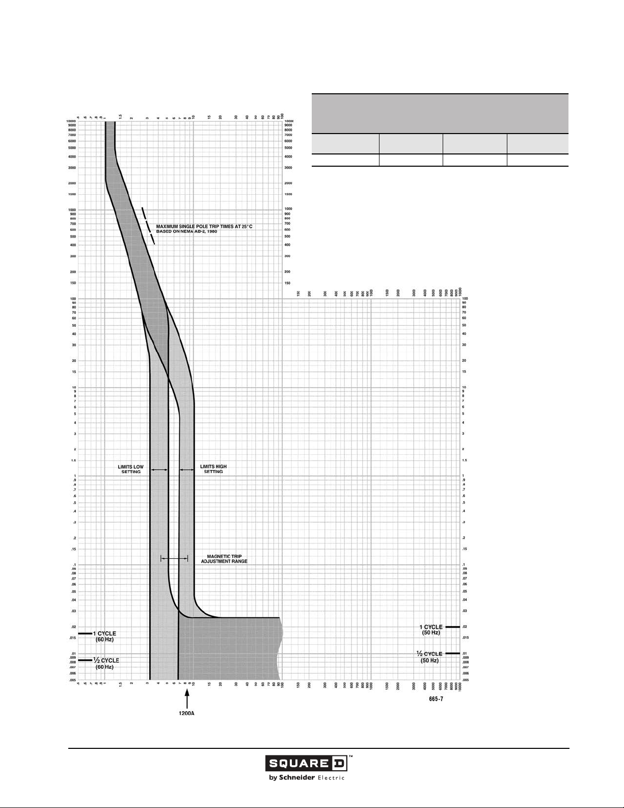
Legacy Thermal-Magnetic / Magnetic Only Molded Case Circuit Breakers
d
MULTIPLES OF RATED CURRENT
MA/MH FAMILY MOLDED CASE CIRCUIT BREAKERS
CHARACTERISTIC TRIP CURVE NO. 665-7
CIRCUIT BREAKER INFORMATION
Circuit Breaker
Prefix
MA/MH 1200 600 3
This curve is to be used for application and coordination purposes only.
The EZ-AMP overlay feature at the bottom of the page should be used during
coordination studies.
All time/current characteristic curve data is based on 104 °F (40 °C) ambient col
start. Terminations are made with conductors of appropriate length and ratings.
Continuous
Ampere Rating
Maximum AC
Voltage
TIME IN SECONDS
Number of Poles
TIME IN SECONDS
Tripping curves for
coordination studies are
available upon request.
Curve No. 0665TC9107
Drawing No. 48095-665-07
MULTIPLES OF RATED CURRENT
88
11/2015 © 1991–2015 Schneider Electric
All Rights Reserved
Page 89
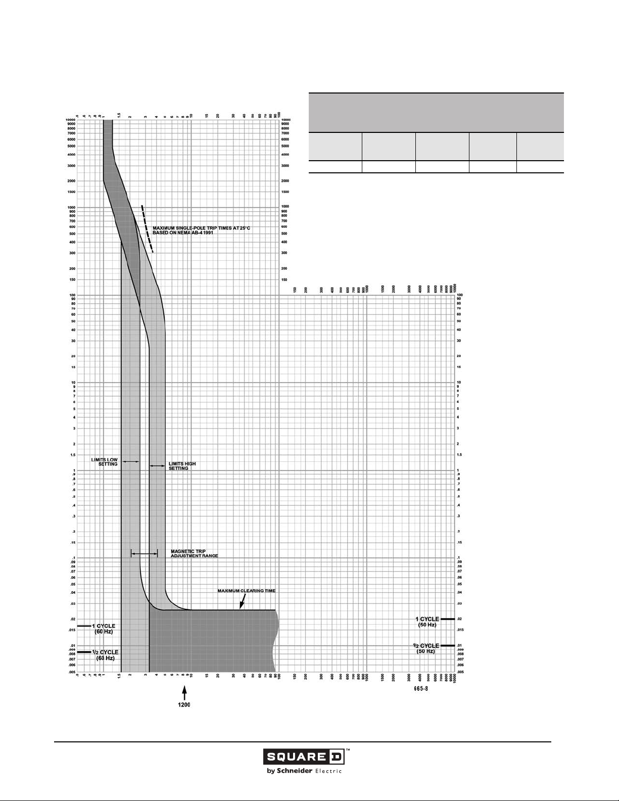
Legacy Thermal-Magnetic / Magnetic Only Molded Case Circuit Breakers
MULTIPLES OF RATED CURRENT
MH THERMAL-MAGNETIC MOLDED CASE CIRCUIT BREAKERS
CHARACTERISTIC TRIP CURVE NO. 665-8
CIRCUIT BREAKER INFORMATION
Circuit
Breaker Prefix
MH 40DC 1200 500 3
This curve is to be used for application and coordination purposes only.
The EZ-AMP overlay feature at the bottom of the page should be used during
coordination studies.
All time/current characteristic curve data is based on 104 °F (40 °C) ambient cold
start. Terminations are made with conductors of appropriate length and ratings.
Circuit
Breaker Suffix
Continuous
Ampere
Rating
Maximum
DC Voltage
TIME IN SECONDS
Number of
Poles
TIME IN SECONDS
Tripping curves for
coordination studies are
available upon request.
Curve No. 0665TC8508
March 2001
Drawing No. B48095-665-08
(Replaces 0655TC9108)
MULTIPLES OF RATED CURRENT
© 1991–2015 Schneider Electric
All Rights Reserved
11/2015
89
Page 90
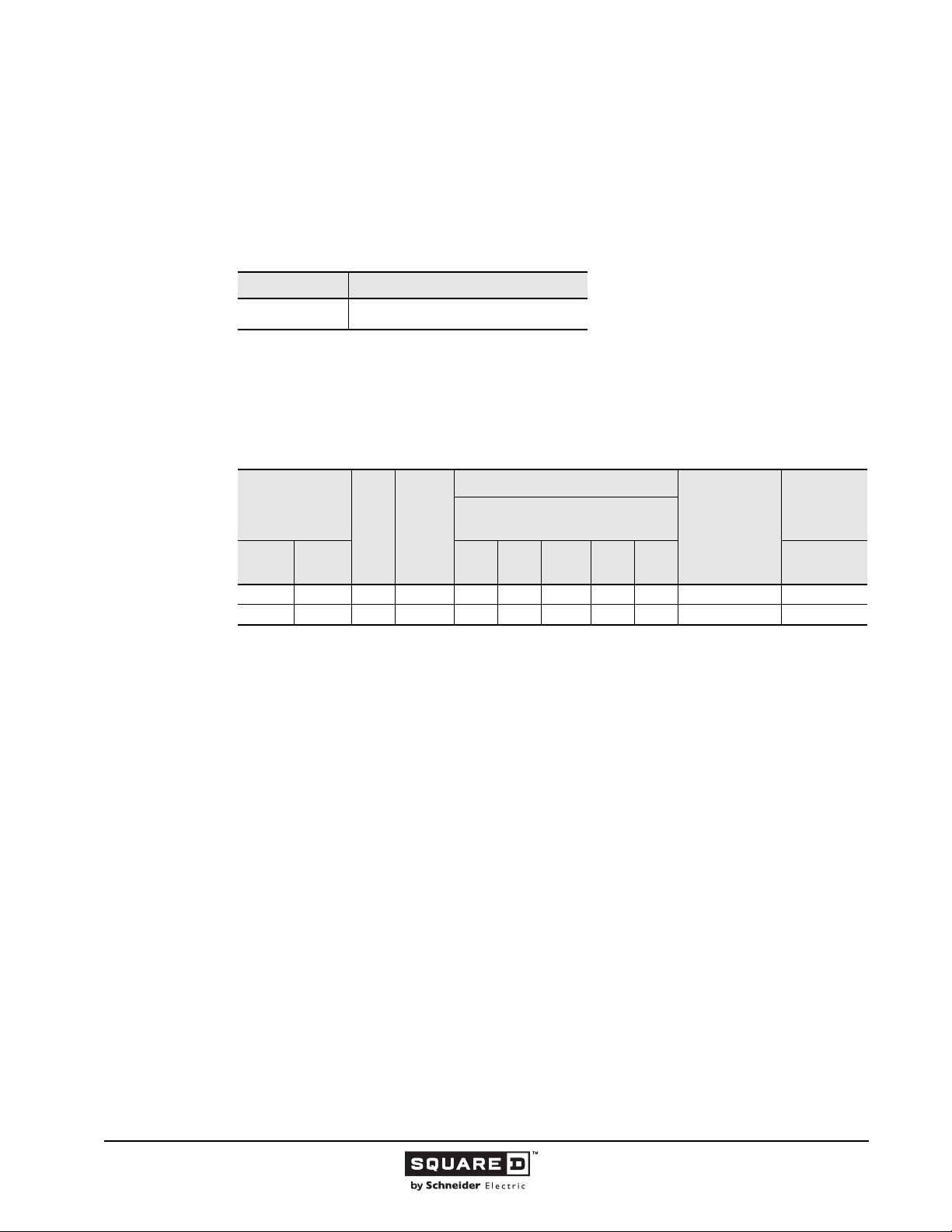
Legacy Thermal-Magnetic / Magnetic Only Molded Case Circuit Breakers
1200 Ampere Frame
This section provides specific information on Schneider Electric 1200 A frame thermal-magnetic
molded case circuit breakers. For more information, see the “Introduction” in this catalog.
Description
Table 27: Description of 1200 A Frame Circuit Breakers
Circuit Breaker Description
NA/NC
Applications
NA and NC circuit breakers are used in industrial enclosures, panelboards and switchboards.
.
Table 28: 1200 A Frame Interrupting Ratings
600–1200 A, 600 Vac, 50/60 Hz,
two- and three-pole
Catalog Number
Prefix
Unit
Mount
NAL NA 2, 3 600–1200 100 100 50 50 25 23a 50/25
NCL NC 2, 3 600–1200 125 125 100 100 65 25a 70/35
I-Line 120 240
No.
of
Poles
Cont.
Ampere
Rating
UL Listed Interrupting Rating (kA)
AC Volts - RMS Symmetrical
Amperes
480Y/
277
480 600 415/240
Federal Specs.
W-C-375B/GEN
IEC 60947-2
Icu/Ics (kA)
AC Voltage
90
11/2015 © 1991–2015 Schneider Electric
All Rights Reserved
Page 91
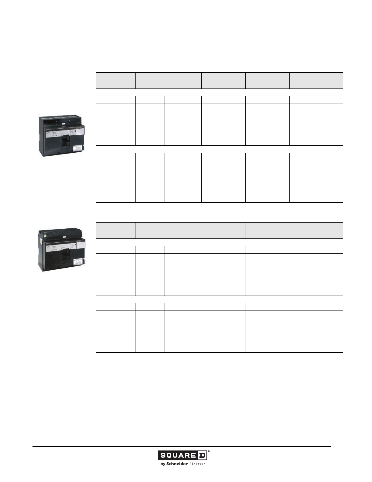
Legacy Thermal-Magnetic / Magnetic Only Molded Case Circuit Breakers
Selection Data
Table 29: 1200 A Unit Mount Circuit Breakers
NAL/NCL
Two- and Three-pole
600–1200 A
NA/NC
Two- and Three-pole
15 in. Mounting Height
600–1200 A
Ampere Rating
NAL High Interrupting
600
700
800
900
1000
1200
NCL Extra High Interrupting
600
700
800
900
1000
1200
AC Magnetic Trip Settings
Low High 600 Vac 600 Vac
4000
4000
4000
5000
5000
5000
Low High 600 Vac 600 Vac
4000
4000
4000
5000
5000
5000
Amperes
8000
8000
8000
10000
10000
10000
8000
8000
8000
10000
10000
10000
Two-Pole
Catalog No.
NAL26600
NAL26700
NAL26800
NAL26900
NAL261000
NAL261200
NCL26600
NCL26700
NCL26800
NCL26900
NCL261000
NCL261200
Three-Pole
Catalog No.
NAL36600
NAL36700
NAL36800
NAL36900
NAL361000
NAL361200
NCL36600
NCL36700
NCL36800
NCL36900
NCL361000
NCL361200
Standard Lug Kit Wire
Range
AL1200NE6
4-#3/0-600 kcmil
AL1200NE6
4-#3/0-600 kcmil
Table 30: 1200 A Frame I-Line Circuit Breakers
Ampere Rating
NA High Interrupting
600
700
800
900
1000
1200
NC Extra High Interrupting
600
700
800
900
1000
1200
1
UL magnetic trip setting tolerances are -20% /+30% (Low) and -20% /+30% (High) from the nominal values shown.
2
Two-pole circuit breaker catalog numbers are completed by adding required phase connection letters as a suffix to the catalog
number.
AC Magnetic Trip Settings
1
Amperes
Low High 240 Vac 240 Vac
4000
4000
4000
5000
5000
5000
Low High 600 Vac/250 Vdc 600 Vac/250 Vdc
4000
4000
4000
5000
5000
5000
8000
8000
8000
10000
10000
10000
8000
8000
8000
10000
10000
10000
Two-Pole
Catalog No.
NA26600( )
NA26700( )
NA26800( )
NA26900( )
NA261000( )
NA261200( )
NC26600( )
NC26700( )
NC26800( )
NC26900( )
NC261000( )
NC261200( )
2
Three-Pole
Catalog No.
NA36600
NA36700
NA36800
NA36900
NA361000
NA361200
NC36600
NC36700
NC36800
NC36900
NC361000
NC361200
Standard Lug Kit Wire
Range
AL1200NE6
4-#3/0-600 kcmil
AL1200NE6
4-#3/0-600 kcmil
© 1991–2015 Schneider Electric
All Rights Reserved
11/2015
91
Page 92
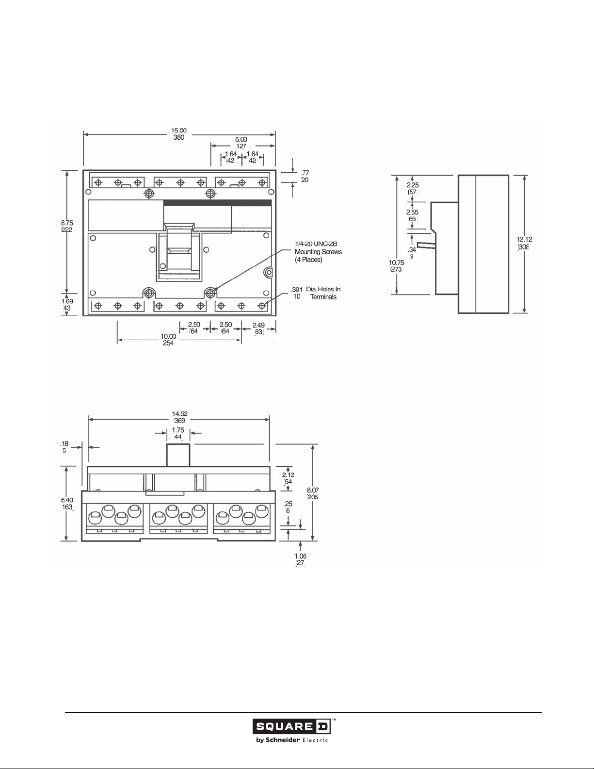
Legacy Thermal-Magnetic / Magnetic Only Molded Case Circuit Breakers
Dimensions
Figure 16: NAL, NCL 1200 A Frame
( )
( )
( )
( )
( )
( ) ( )
( )( )
( )
( )
( )
( )
( )
( )
( )
( )
( )
( )
( )
( )
( )
( )
( )
( )
Dimensions:
in.
(mm)
92
11/2015 © 1991–2015 Schneider Electric
All Rights Reserved
Page 93
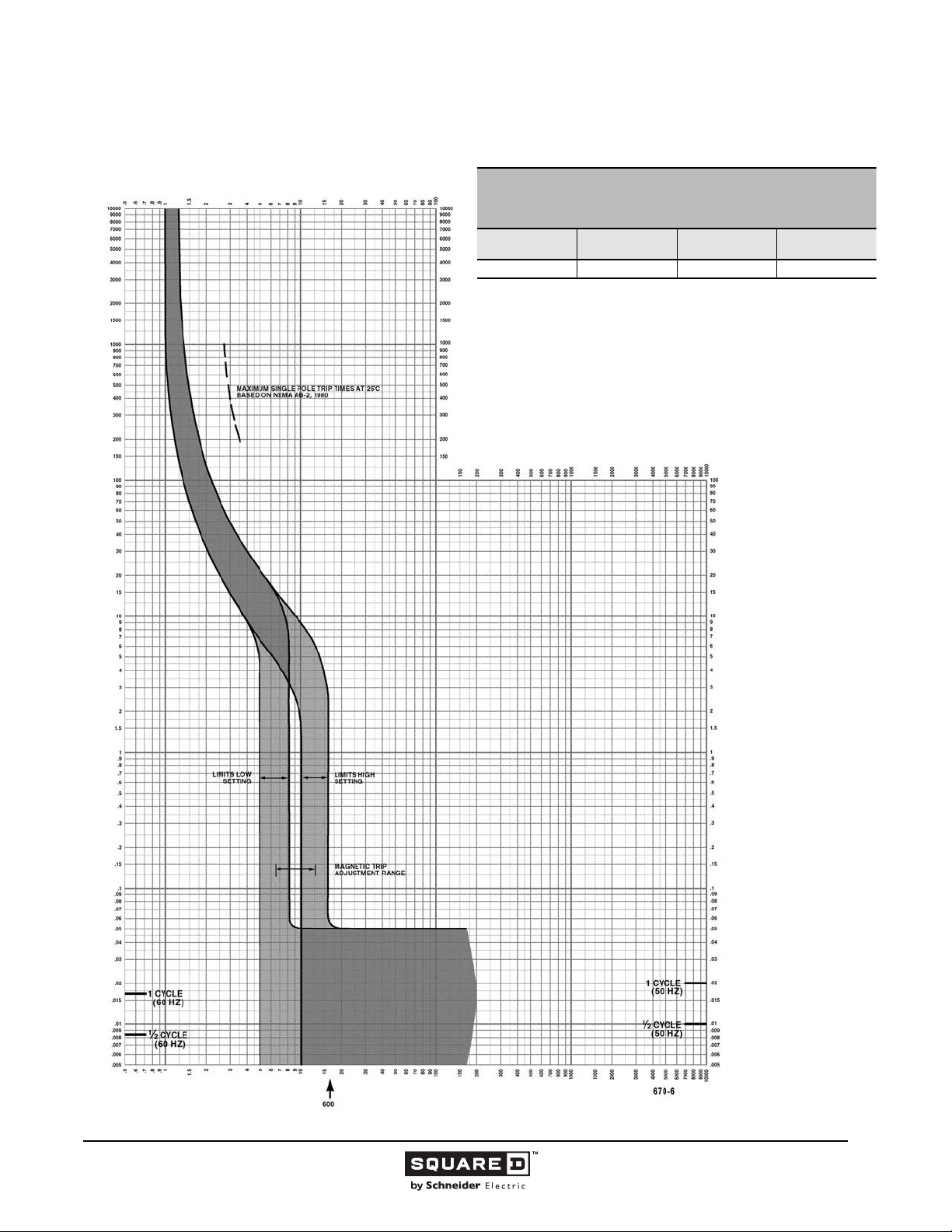
Legacy Thermal-Magnetic / Magnetic Only Molded Case Circuit Breakers
Tripping Curves
MULTIPLES OF RATED CURRENT
NA FAMILY MOLDED CASE CIRCUIT BREAKERS
CHARACTERISTIC TRIP CURVE NO. 670-6
CIRCUIT BREAKER INFORMATION
Circuit Breaker
Prefix
NA, NC 600 600 2, 3
This curve is to be used for application and coordination purposes only.
The EZ-AMP overlay feature at the bottom of the page should be used during
coordination studies.
All time/current characteristic curve data is based on 104 °F (40 °C) ambient cold
start. Terminations are made with conductors of appropriate length and ratings.
Continuous
Ampere Rating
Maximum AC
Voltage
TIME IN SECONDS
Number of Poles
TIME IN SECONDS
Tripping curves for
coordination studies are
available upon request.
Curve No. 0670TC8706
Drawing No. 48095-670-06
MULTIPLES OF RATED CURRENT
© 1991–2015 Schneider Electric
All Rights Reserved
11/2015
93
Page 94
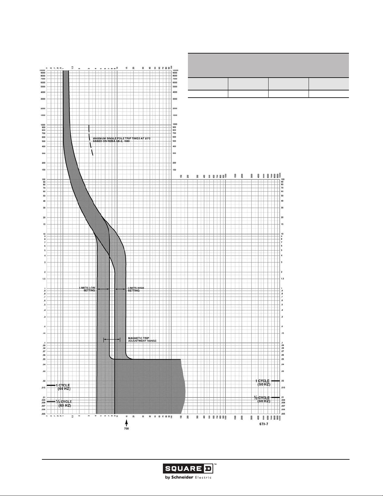
Legacy Thermal-Magnetic / Magnetic Only Molded Case Circuit Breakers
MULTIPLES OF RATED CURRENT
NA FAMILY MOLDED CASE CIRCUIT BREAKERS
CHARACTERISTIC TRIP CURVE NO. 670-7
CIRCUIT BREAKER INFORMATION
Circuit Breaker
Prefix
NA, NC 700 600 2, 3
This curve is to be used for application and coordination purposes only.
The EZ-AMP overlay feature at the bottom of the page should be used during
coordination studies.
All time/current characteristic curve data is based on 104 °F (40 °C) ambient cold
start. Terminations are made with conductors of appropriate length and ratings.
Continuous
Ampere Rating
Maximum AC
Voltage
TIME IN SECONDS
Number of Poles
TIME IN SECONDS
Tripping curves for
coordination studies are
available upon request.
Curve No. 0670TC8707
Drawing No. 48095-670-07
MULTIPLES OF RATED CURRENT
94
11/2015 © 1991–2015 Schneider Electric
All Rights Reserved
Page 95
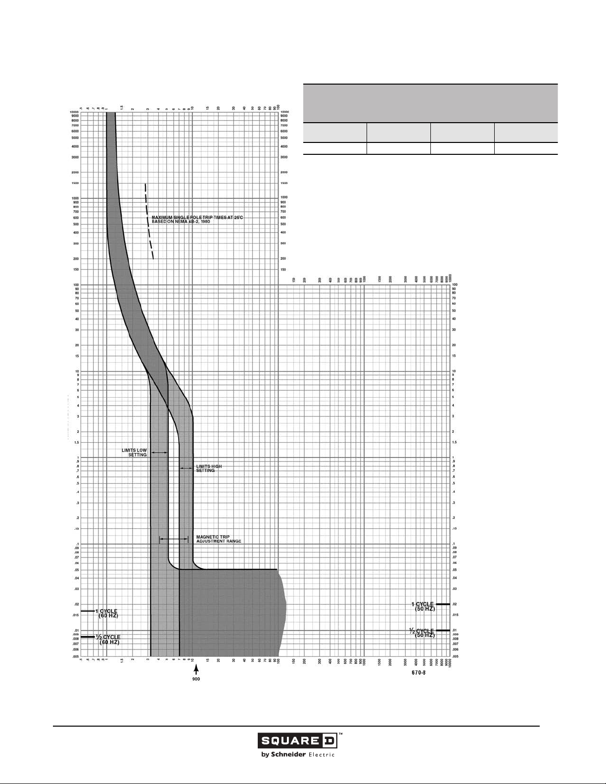
Legacy Thermal-Magnetic / Magnetic Only Molded Case Circuit Breakers
MULTIPLES OF RATED CURRENT
NA FAMILY MOLDED CASE CIRCUIT BREAKERS
CHARACTERISTIC TRIP CURVE NO. 670-8
CIRCUIT BREAKER INFORMATION
Circuit Breaker
Prefix
NA, NC 900 600 2, 3
This curve is to be used for application and coordination purposes only.
The EZ-AMP overlay feature at the bottom of the page should be used during
coordination studies.
All time/current characteristic curve data is based on 104 °F (40 °C) ambient cold
start. Terminations are made with conductors of appropriate length and ratings.
Continuous
Ampere Rating
Maximum AC
Voltage
TIME IN SECONDS
Number of Poles
TIME IN SECONDS
Tripping curves for
coordination studies are
available upon request.
Curve No. 0670TC8708
Drawing No. 48095-670-08
MULTIPLES OF RATED CURRENT
© 1991–2015 Schneider Electric
All Rights Reserved
11/2015
95
Page 96
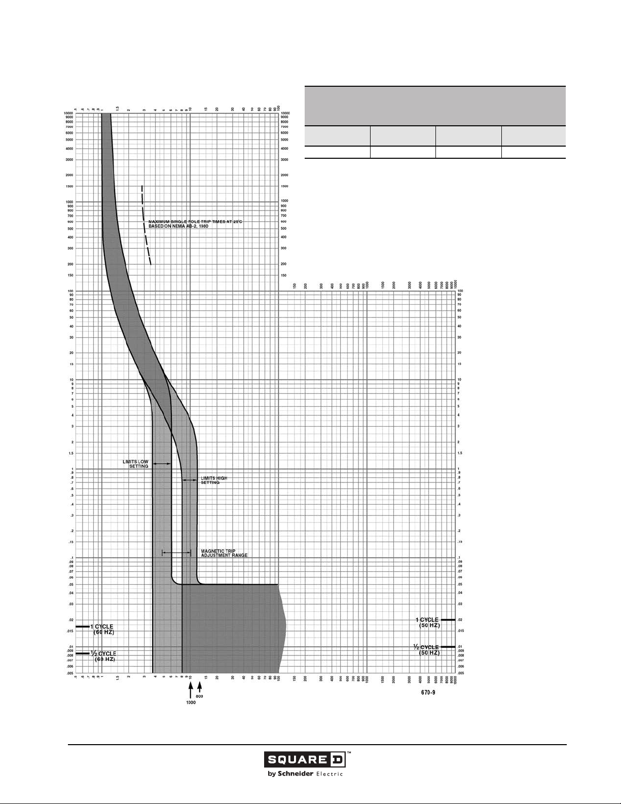
Legacy Thermal-Magnetic / Magnetic Only Molded Case Circuit Breakers
MULTIPLES OF RATED CURRENT
NA FAMILY MOLDED CASE CIRCUIT BREAKERS
CHARACTERISTIC TRIP CURVE NO. 670-9
CIRCUIT BREAKER INFORMATION
Circuit Breaker
Prefix
NA, NC 800 & 1000 600 2, 3
This curve is to be used for application and coordination purposes only.
The EZ-AMP overlay feature at the bottom of the page should be used during
coordination studies.
All time/current characteristic curve data is based on 104 °F (40 °C) ambient cold
start. Terminations are made with conductors of appropriate length and ratings.
Continuous
Ampere Rating
Maximum AC
Voltage
TIME IN SECONDS
Number of Poles
TIME IN SECONDS
Tripping curves for
coordination studies are
available upon request.
Curve No. 0670TC8709
Drawing No. 48095-670-09
MULTIPLES OF RATED CURRENT
96
11/2015 © 1991–2015 Schneider Electric
All Rights Reserved
Page 97
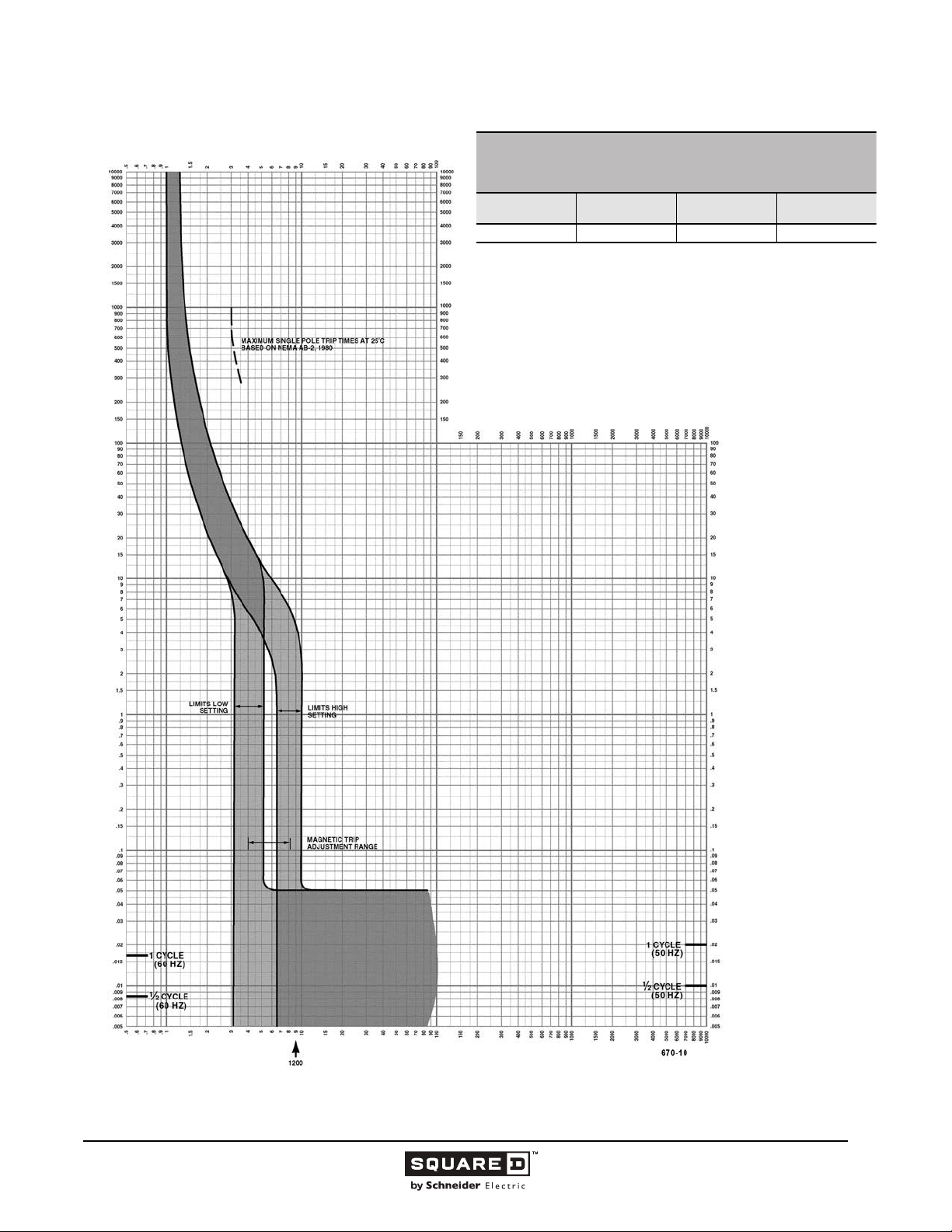
Legacy Thermal-Magnetic / Magnetic Only Molded Case Circuit Breakers
MULTIPLES OF RATED CURRENT
NA FAMILY MOLDED CASE CIRCUIT BREAKERS
CHARACTERISTIC TRIP CURVE NO. 670-10
CIRCUIT BREAKER INFORMATION
Circuit Breaker
Prefix
NA, NC 1200 600 2, 3
This curve is to be used for application and coordination purposes only.
The EZ-AMP overlay feature at the bottom of the page should be used during
coordination studies.
All time/current characteristic curve data is based on 104 °F (40 °C) ambient cold
start. Terminations are made with conductors of appropriate length and ratings.
Continuous
Ampere Rating
Maximum AC
Voltage
TIME IN SECONDS
Number of Poles
TIME IN SECONDS
Tripping curves for
coordination studies are
available upon request.
Curve No. 0670TC8710
Drawing No. 48095-670-10
MULTIPLES OF RATED CURRENT
© 1991–2015 Schneider Electric
All Rights Reserved
11/2015
97
Page 98
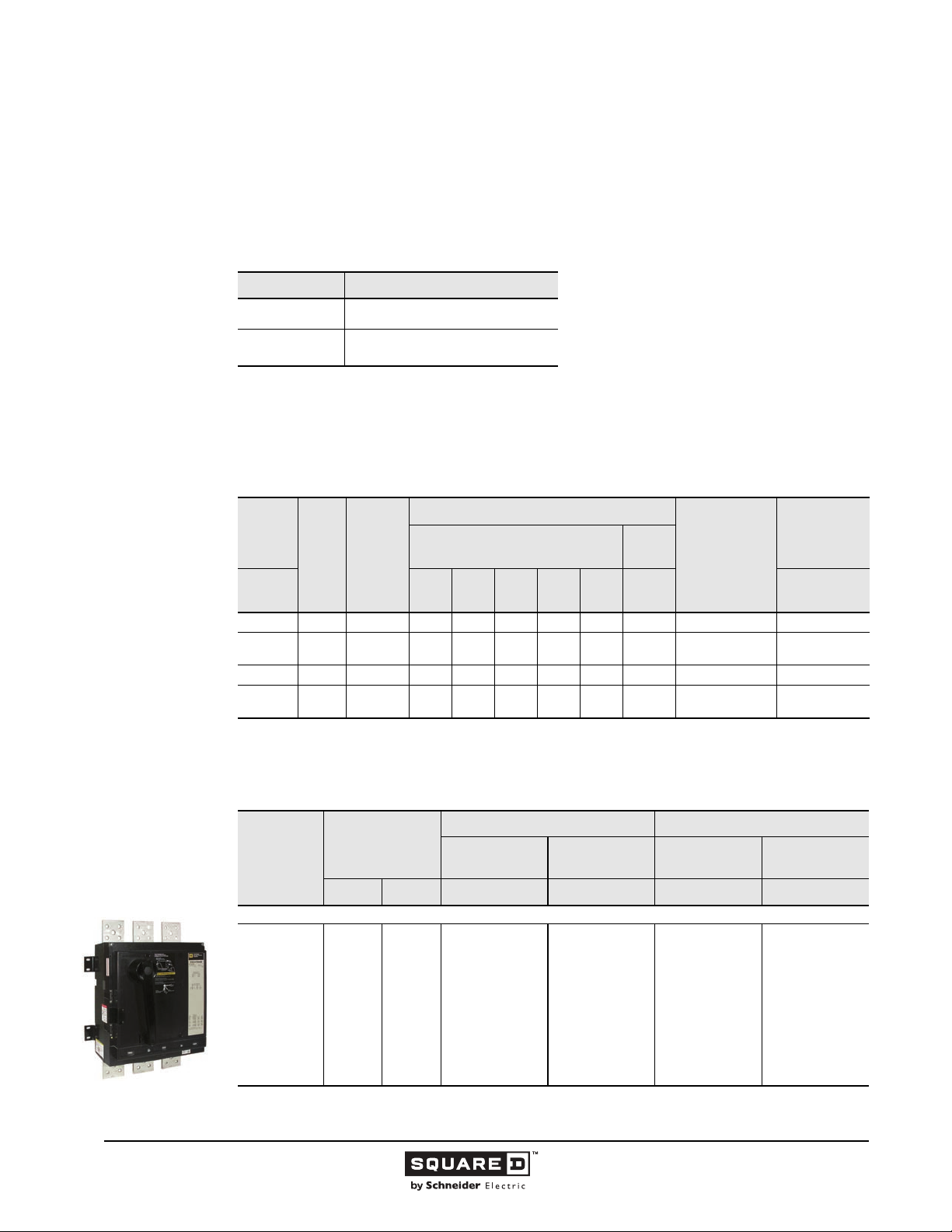
Legacy Thermal-Magnetic / Magnetic Only Molded Case Circuit Breakers
2000 / 2500 Ampere Frame
This section provides specific information on Schneider Electric 2000 / 2500 A frame thermal-magnetic
molded case circuit breakers. For more information, see the “Introduction” in this catalog.
Description
Table 31: Description of 2000 / 2500 A Frame Circuit Breakers
Circuit Breaker Description
PAF/PHF
PCF
Applications
PAF, PHF and PCF circuit breakers are used in industrial enclosures, switchboards and busway
plug-in units.
.
Table 32: 2000 / 2500 A Frame Interrupting Ratings
600–2000 A, 600 Vac, 50/60 Hz,
two- and three-pole
600–2500 A, 600 Vac, 50/60 Hz,
two- and three-pole
Catalog
Number
Prefix
No. of
Poles
Cont.
Ampere
Rating
Unit
Mount
PAF 2, 3 600–1200 65 65 50 50 42 — 24a 50
PAF-DC 3
1
PHF
PCF
1
Separate UL rating available for 240 Vac and 480 Vac grounded B single phase systems. Circuit breakers must be ordered with
5861 suffix. See Supplemental Digest for specific ratings.
2, 3 600–2000 125 125 100 100 65 — 25a 100
1
2, 3
1200–
2000
1600–
2500
UL Listed Interrupting Rating (kA)
AC Volts - RMS Symmetrical
Amperes
120 240
—————25K — —
125 125 100 100 65 — 25a 100
480Y/
277
480 600 500 415/240
DC
Volts
Federal Specs.
W-C-375B/GEN
IEC 60947-2
Icu/Ics (kA)
AC Voltage
Selection Data
Table 33: 2000 A Unit Mount Circuit Breakers
AC Magnetic
Ampere
Rating
Trip Settings
Amperes
1
Low High Catalog No. Kit Catalog No. Catalog No. Kit Catalog No.
PAF Standard Interrupting - Complete Breaker Requires Frame and Rating Columns
PAF/PHF
Two- and Three-pole
600–2000 A
600
700
800
1000
1200
1400
1600
1800
2000
1
UL magnetic trip setting tolerances are -20% /+30% (Low) and -20% /+30% (High) from the nominal values shown.
3200
3200
3200
3500
3500
4500
5000
6500
8000
9000
9000
9000
9000
9000
9000
10000
11000
12000
98
11/2015 © 1991–2015 Schneider Electric
Two-Pole, 600 Vac Three-Pole, 600 Vac
Frame Only
PAF2026
Rating Columns
Two Per Kit
PA2600RC
PA2700RC
PA2800RC
PA21000RC
PA21200RC
PA21400RC
PA21600RC
PA21800RC
PA22000RC
Frame Only
PAF2036
—Continued on next page
Rating Columns
Three Per Kit
PA3600RC
PA3700RC
PA3800RC
PA31000RC
PA31200RC
PA31400RC
PA31600RC
PA31800RC
PA32000RC
All Rights Reserved
Page 99
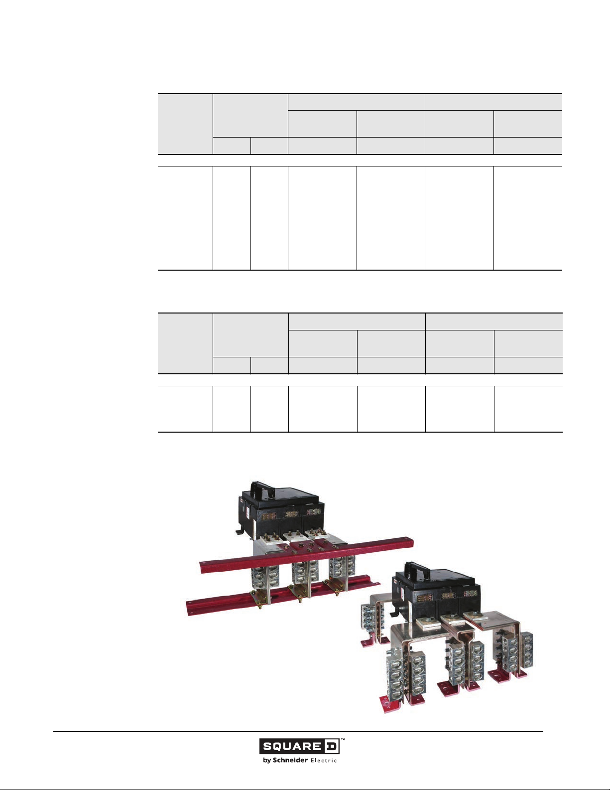
Legacy Thermal-Magnetic / Magnetic Only Molded Case Circuit Breakers
Table 33: 2000 A Unit Mount Circuit Breakers (continued)
Two-Pole, 600 Vac Three-Pole, 600 Vac
Frame Only
Rating Columns
Two Per Kit
Frame Only
Ampere
Rating
AC Magnetic
Trip Settings
Amperes
1
Low High Catalog No. Kit Catalog No. Catalog No. Kit Catalog No.
PHF High Interrupting - Complete Breaker Requires Frame and Rating Columns
600
700
800
1000
1200
1400
1600
1800
2000
1
UL magnetic trip setting tolerances are -20% /+30% (Low) and -20% /+30% (High) from the nominal values shown.
3200
3200
3200
3500
3500
4500
5000
6500
8000
9000
9000
9000
9000
9000
9000
10000
11000
12000
PHF2026
PA2600RC
PA2700RC
PA2800RC
PA21000RC
PA21200RC
PA21400RC
PA21600RC
PA21800RC
PA22000RC
PHF2036
Table 34: 2500 A Unit Mount Circuit Breakers
AC Magnetic
Ampere
Rating
Trip Settings
Amperes
1
Low High Catalog No. Kit Catalog No. Catalog No. Kit Catalog No.
PCF High Interrupting - Complete Circuit Breaker Requires Frame and Rating Columns
1600
1800
2000
2500
1
UL magnetic trip setting tolerances are -20% /+30% (Low) and -20% /+30% (High) from the nominal values shown.
6000
6000
6000
8000
12000
12000
12000
14000
Two-Pole, 600 Vac Three-Pole, 600 Vac
Frame Only
PCF2526
Rating Columns
Two Per Kit
PC21600RC
PC21800RC
PC22000RC
PC22500RC
Frame Only
PCF2536
Rating Columns
Three Per Kit
PA3600RC
PA3700RC
PA3800RC
PA31000RC
PA31200RC
PA31400RC
PA31600RC
PA31800RC
PA32000RC
Rating Columns
Three Per Kit
PC31600RC
PC31800RC
PC32000RC
PC32500RC
Figure 17: PAF/PCF Circuit Breaker with Terminal Pad Kit
© 1991–2015 Schneider Electric
All Rights Reserved
PAF circuit breaker with one optional PAL-TB terminal pad
kit end 18 optional lugs installed. Kits mount on either end
of the circuit breaker. Each kit contains three terminal pads,
one per phase, with provisions for mounting a maximum of
six lugs per pad. Lugs (Cat. No AL2500PA) must be
ordered separately.
PCF circuit breakers are supplied with a terminal pad kit as
standard for line and load cable terminations. The pad kit
allows mounting a maximum of eight lugs per pad. Lugs
(Cat. No. AL2500PA) must be ordered separately.
99
11/2015
Page 100
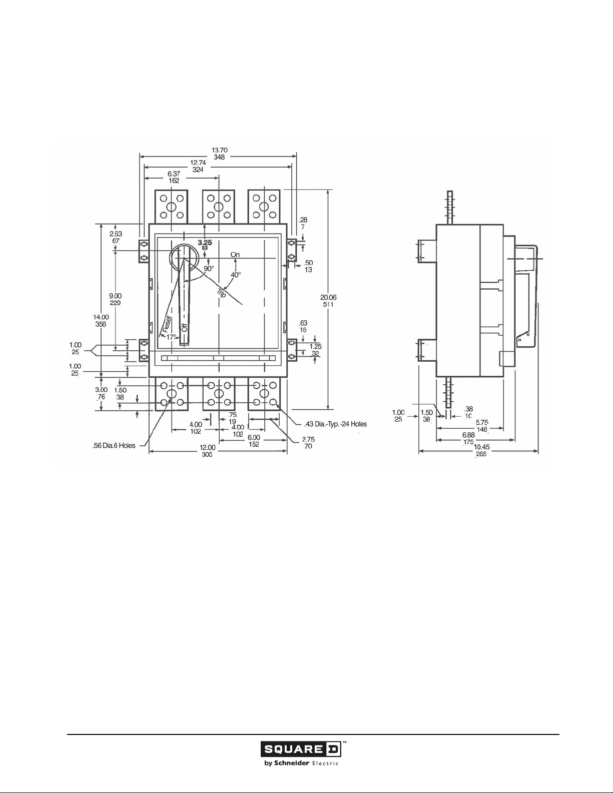
Legacy Thermal-Magnetic / Magnetic Only Molded Case Circuit Breakers
Dimensions
Figure 18: PAF, PHF 2000 A Frame
( )
( )
( )
( )
( )
( )
( )
( )
( )
( )
( )
( )
( )
( )
( )
( )
( )
( )
( )
( )
( )
( ) ( )
( )
( )
( )
( )
Dimensions:
in.
(mm)
100
11/2015 © 1991–2015 Schneider Electric
All Rights Reserved
 Loading...