


Contents
Harmony™ 9001K/SK/KX
30 mm push buttons
Introduction . . . . . . . . . . . . . . . . . . . . . . . . . . . . . . . . . . . . . . . . . 4
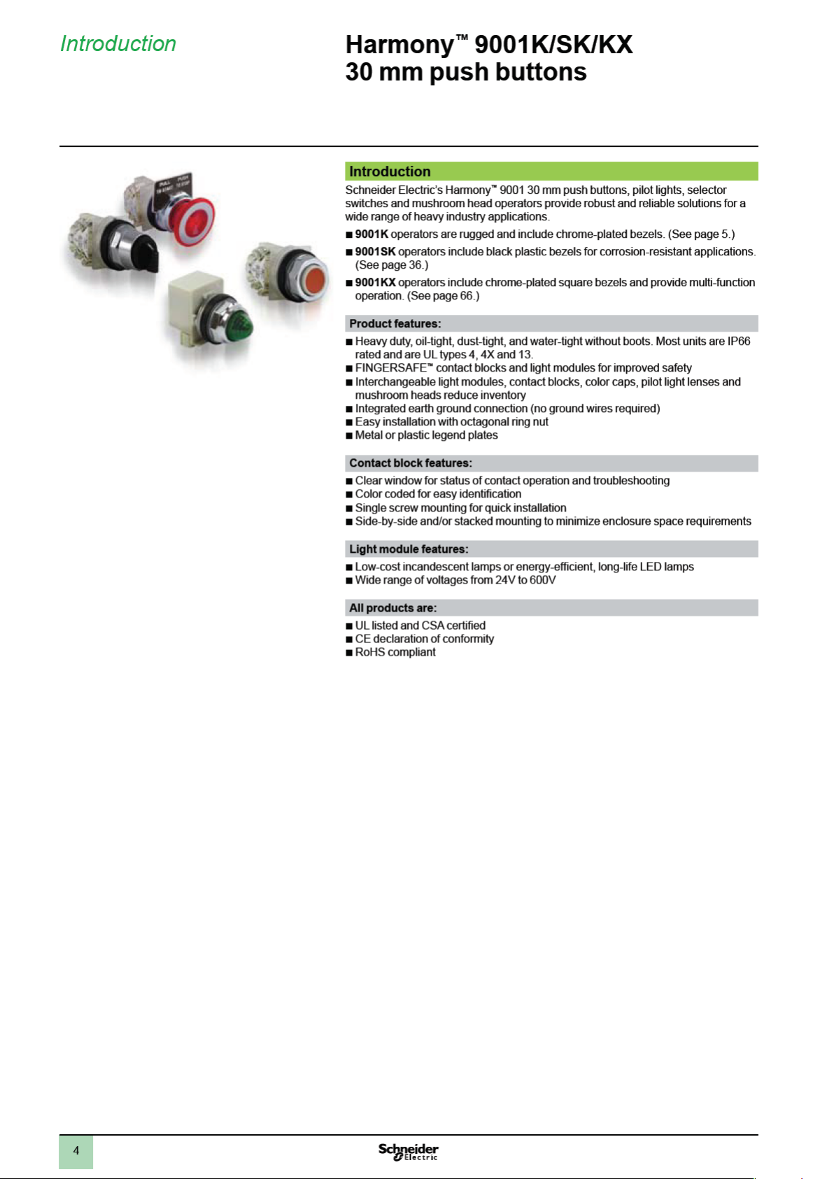
9001K heavy-duty operators with chrome-plated bezels:
Product range . . . . . . . . . . . . . . . . . . . . . . . . . . . . . . . . . . . . . . . 5
Specications . . . . . . . . . . . . . . . . . . . . . . . . . . . . . . . . . . . . . . . 7
References
v
Push buttons and mushroom operators
v
Multi-function operators
v
Selector switches
v
Pilot lights
v
Specialty operators
v
Contact blocks
v
Light modules
v
Legend plates
v
Accessories
v
Replacement parts
. . . . . . . . . . . . . . . . . . . . . . . . . . . . . . . . . . . . . . . . 17
. . . . . . . . . . . . . . . . . . . . . . . . . . . . . . . . . . . . . 20
......................................24
......................................25
.......................................27
...............................12
...................................13
. . . . . . . . . . . . . . . . . . . . . . . . . . . . . . . . . . 18
...................................29
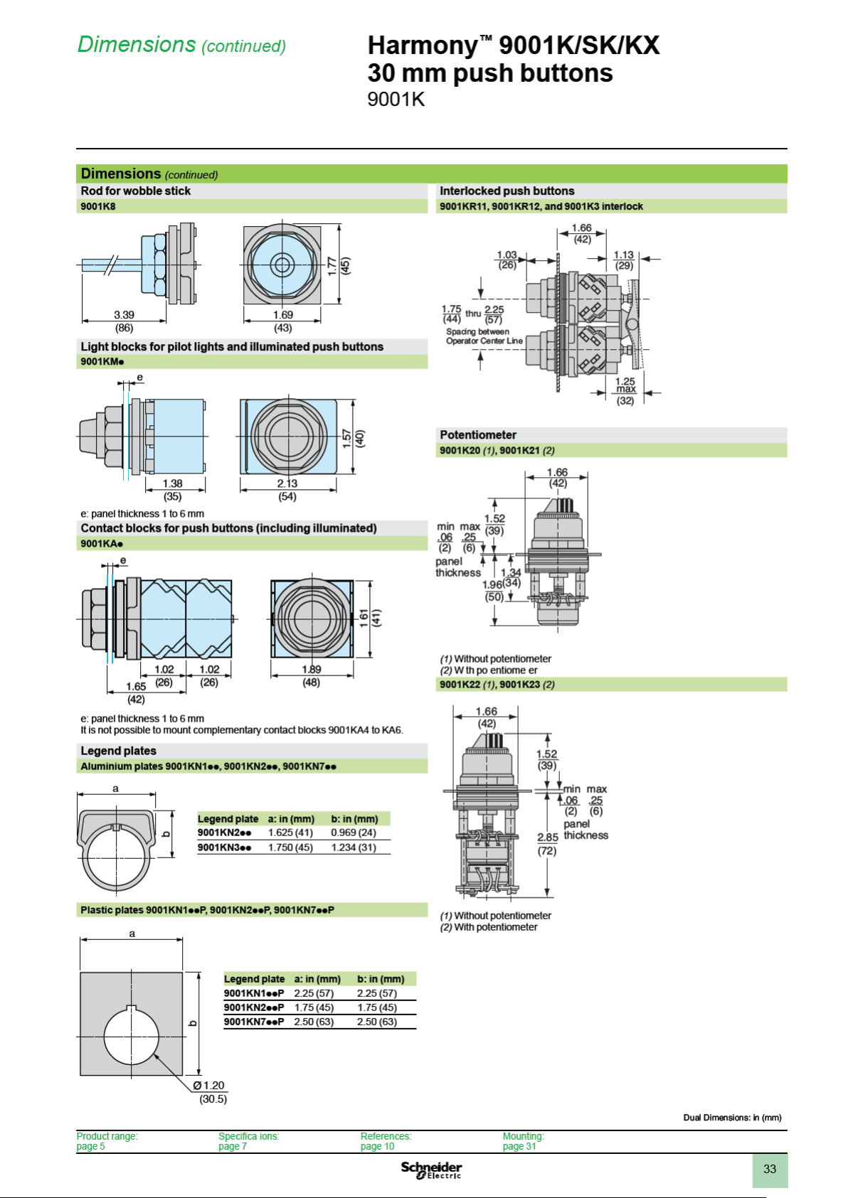
Dimensions . . . . . . . . . . . . . . . . . . . . . . . . . . . . . . . . . . . . . . . . 30
.....................10
9001SK corrosion-resistant operators with black plastic bezels:
Product range . . . . . . . . . . . . . . . . . . . . . . . . . . . . . . . . . . . . . . 36
Specications . . . . . . . . . . . . . . . . . . . . . . . . . . . . . . . . . . . . . . 38
References
v
Push buttons and mushroom operators
v
Multi-function operators
v
Selector switches
v
Pilot lights
v
Specialty operators
v
Contact blocks
v
Light modules
v
Legend plates
v
Accessories
v
Replacement parts
. . . . . . . . . . . . . . . . . . . . . . . . . . . . . . . . . . . . . . . . 48
. . . . . . . . . . . . . . . . . . . . . . . . . . . . . . . . . . . . . 50
......................................54
......................................55
.......................................57
...............................43
...................................44
. . . . . . . . . . . . . . . . . . . . . . . . . . . . . . . . . . 49
...................................59
.....................41
Dimensions . . . . . . . . . . . . . . . . . . . . . . . . . . . . . . . . . . . . . . . . 60
9001KX multi-function operators with chrome-plated
square-head bezels:
Product range . . . . . . . . . . . . . . . . . . . . . . . . . . . . . . . . . . . . . . 66
Specications . . . . . . . . . . . . . . . . . . . . . . . . . . . . . . . . . . . . . . 67
References
v
Push buttons with contacts
v
Push buttons without contacts
v
Selector switches
v
Contact blocks
v
Pilot lights
v
Legend plates
v
Accessories
...................................72
. . . . . . . . . . . . . . . . . . . . . . . . . . . . . . . . . . . . . 72
. . . . . . . . . . . . . . . . . . . . . . . . . . . . . . . . . . . . . . . . 73
......................................74
.......................................75
.............................70
...........................71
Dimensions . . . . . . . . . . . . . . . . . . . . . . . . . . . . . . . . . . . . . . . . 76
Index ..............................................78
3


8
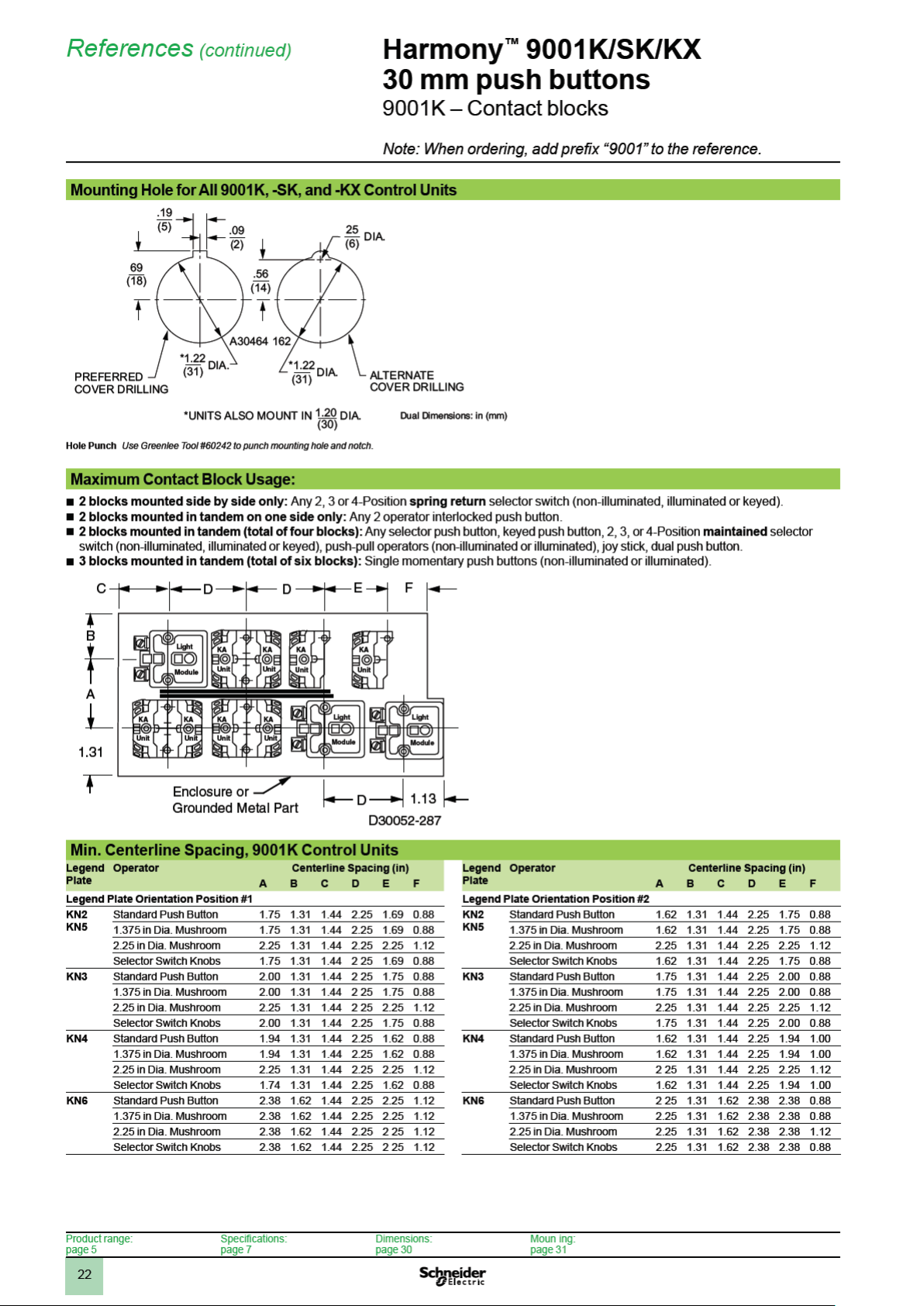
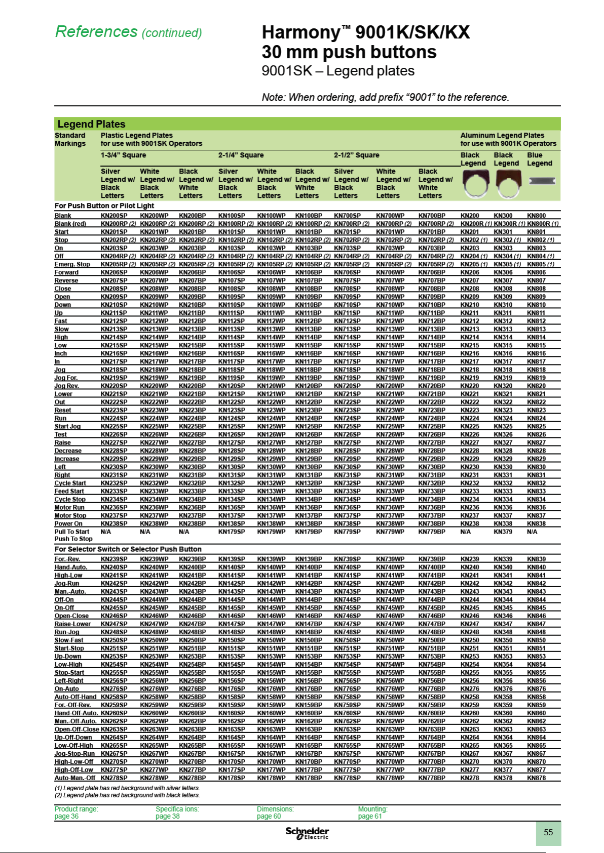
Specications (continued)
Harmony™ 9001K/SK/KX
30 mm push buttons
9001K
Basic Operators
(For Color Caps, Mushroom Buttons, Knobs, Se lector Switch Cams, Contact Blocks, Light Modules and Legend Plates, see page 21.)
Description UL Types/NEMA Types
4, 13
Non Illuminated Push Button (Full Guard) 9001KR1
Non Illuminated Push Button (Extended Guard) 9001KR2
Non Illuminated Push Button (No Guard) 9001KR3
Non Illuminated Push Button (Mushroom Button/screw on) 9001KR20
Non Illuminated Dual Push Button (Momentary) 9001KR6
Non Illuminated Dual Push Button (Momentary Interlocked) 9001KR67
Non Illuminated Dual Push Button (Maintained Interlocked) 9001KR7
Momentary Pull - Maintained Neutral - Momentary Push 9001KR8 (1) (4)
Maintained Pull - Maintained Push 9001KR9 (1) (4)
lluminated Push Button (Full Guard - Plastic Top) 9001K1L (2)
lluminated Push Button and Push-to-test (No Guard) 9001K2L (2) (3)
lluminated Push Button (Full Guard - Metal Top) 9001K3L (2)
Standard Pilot Light 9001KP
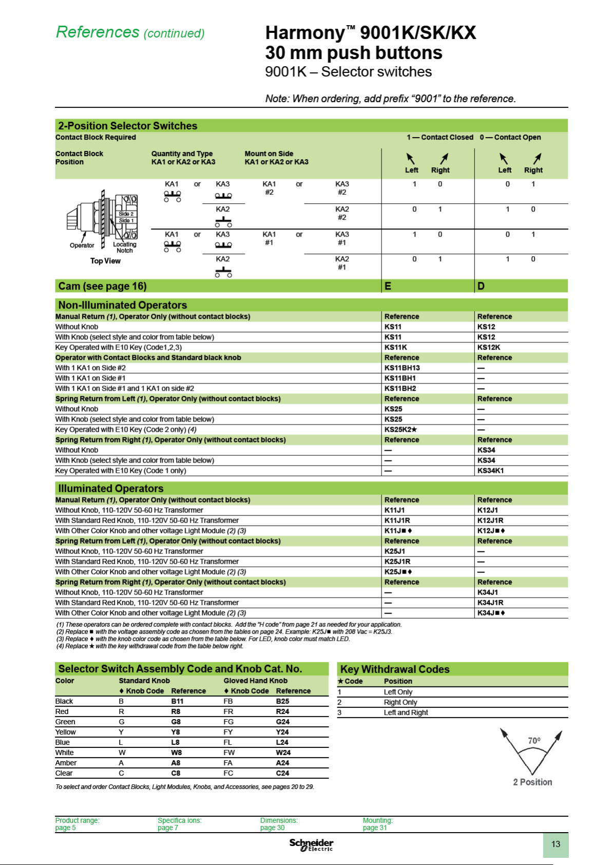
2-Position Selector Switch 9001KS1 (1), 9001KS2 (1), 9001KS3 (1)
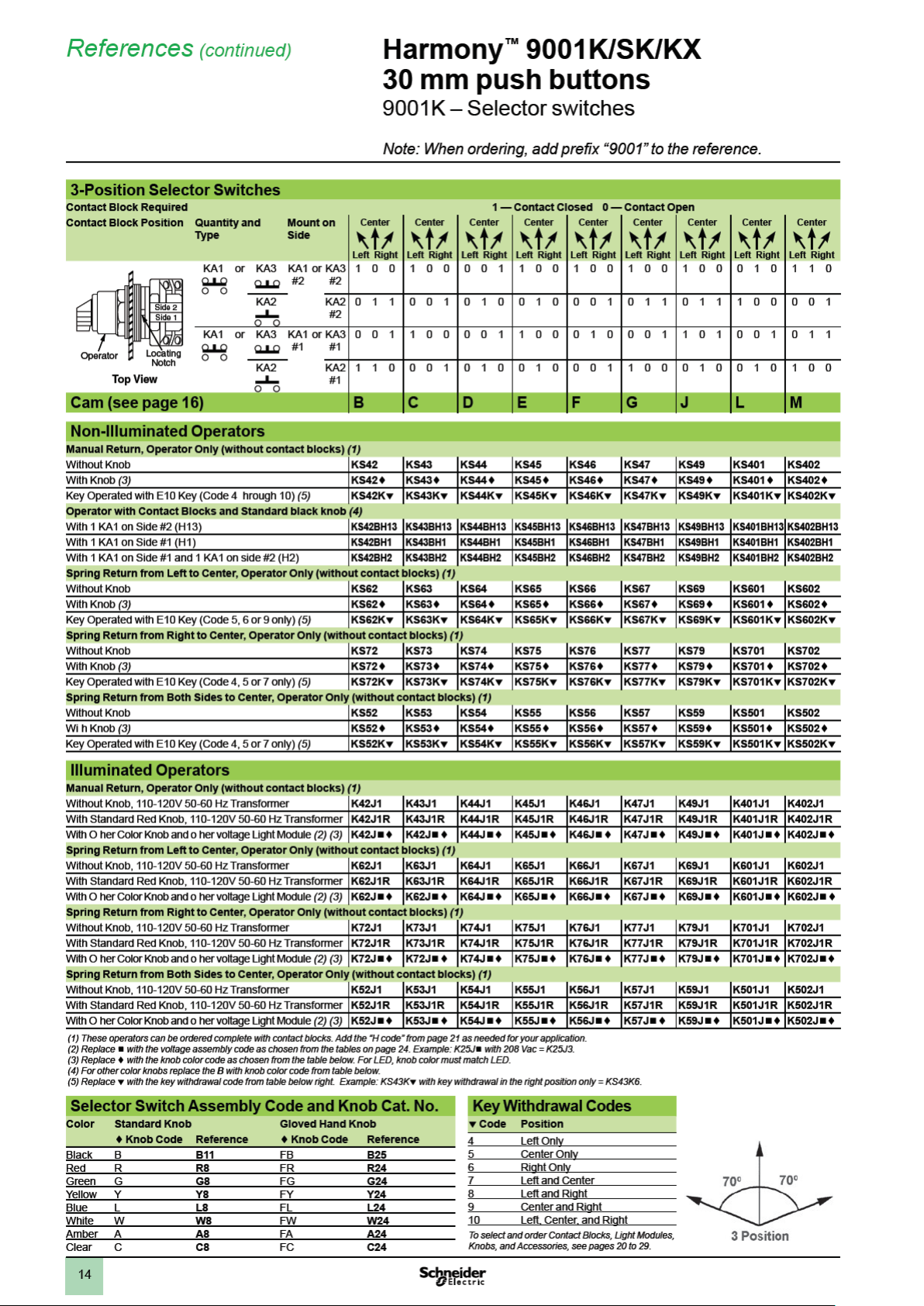
3-Position Selector Switch 9001KS4 (1), 9001KS5 (1), 9001KS6 (1), 9001KS7 (1)
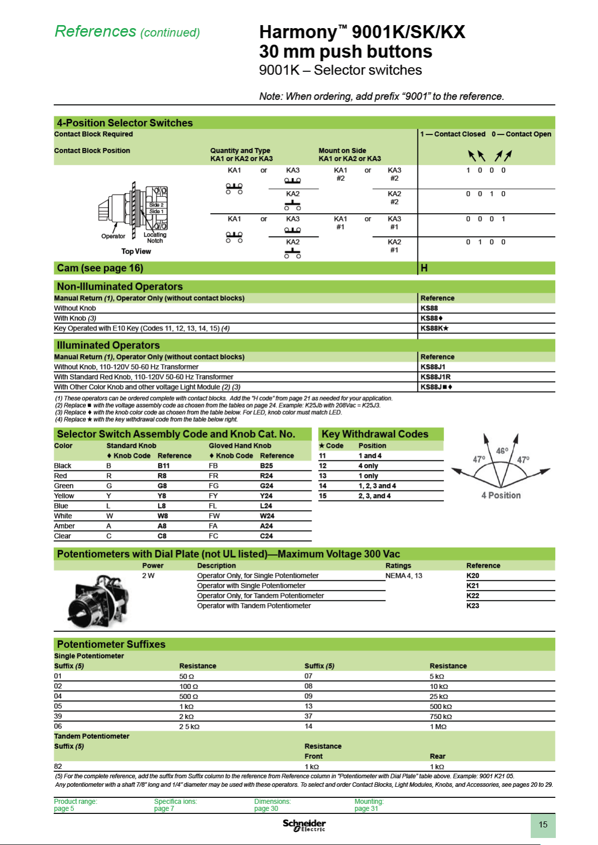
4-Position Selector Switch 9001KS8 (1)
Trigger-Action Emergency Stop 9001KR16 (1)
(1) Operator can be converted to an illuminated operator by removing the liner (6509704901) and adding a light module.
(2) Operator can be converted to a non-illuminated operator by adding liner (6509704901).
(3) Operator includes jumper wires for push-to-test conversion.
(4) These operators can be supplied with 1-3/8" or 2-1/4" dia. mushroom buttons. For 1-3/8" Add •20 to reference number. The • refers to the color chosen - see page 10.
For 2-1/4": Add •21 to reference number. The • refers to the color chosen - see page 10. Voids UL and NEMA Type 6 Rating.
Non Hazardous Locations:
File
CCN
E42259
NKCR
File
Class
LR25490
3211 03
Marking
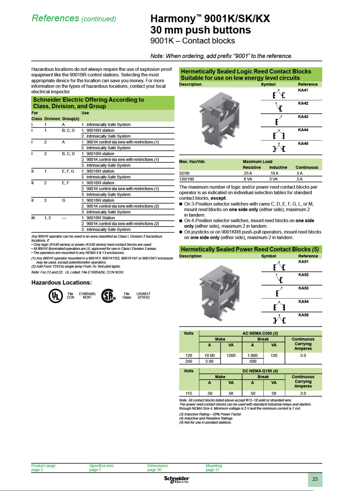
Hazardous Locations (Reed contact blocks, see page 23):
File
CCN
E10054
NOIV
File
Class
LR26817
3218 02
Marking
Product range:
page 5
References:
page 10
Dimensions:
page 30
Moun ing:
page 31

9
Specications (continued)
Harmony™ 9001K/SK/KX
30 mm push buttons
9001K
9001K Operator Materials:
Push Button and Push-to-test Pilot Light
(9001KR and 9001KT)
Gasket – Nitrile
Seal – Nitrile
Seal Cap – Amorphous Acetal
Decorative Ring – Polyester Film
Compensating Washer – Polypropylene
Lock Ring – Amorphous Nylon
Stem – Thermoplastic Polyester
Base Cap – Thermoplastic Polyester
Knob – Polycarbonate
Liner – Polypropylene
Hold Down Spring for 9001K-15 – Neoprene
Operator Base – Zinc
Operator Base (9001KR8) – Polyester
Return Spring – Music Wire or Stainless Steel (9001KT only)
Ring Nuts – Aluminum or Zinc
Springkeeper – Steel
Locking Thrust Washer – Zinc
Color Insert – Polyethylene
Boots – Silicone
Selector Switch (9001KS)
Gasket – Nitrile
Seal – Nitrile
Bearing Washer – Polyester Film
Compensating Washer – Polypropylene
Cam Follower – Delrin 100
Liner – Polypropylene
Knob – Polycarbonate
Cam Carrier – Amorphous Nylon
Cam Rotor – Celenex 3300
Cam Prole– Delrin 100
Operator Base – Zinc
Detent Spring – Stainless Steel
Ring Nuts – Aluminum or Zinc
Seal keeper – Stainless Steel
Locking Thrust Washer – Zinc
Contact Block And Light Module Materials:
Contact Block (9001KA)
Housing – Amorphous Nylon
Contact Slider – Phenolic, Nylon or Acetal
Terminal – Steel
Saddle Clamp – Steel
Spring – Stainless Steel
Contacts – Silver and Copper
Blade – Beryllium Copper
Mounting Screw – Steel
Label – Paper
Light Module (9001KM)
Housing – Thermoplastic Polyester
Socket – Steel
Terminal – Steel with Tin Plate
Saddle Clamp – Steel
Translating Pin – Polycarbonate
Transformer – Thermoplastic Polyester, Steel, Copper,
Polyvinyl Chloride, Polytetrauorethylene,
Acetate, Paper
Lamp Spring – Tin Plated Music Wire
Pilot Light (9001KP)
Gasket – Nitrile
Compensating Washer – Polypropylene
Lens – Glass or Polycarbonate
Light Module Housing – Thermoplastic Polyester
Operator Base – Zinc
Glass Lens Ring – Anodized Aluminum
Product range:
page 5
References:
page 10
Dimensions:
page 30
Mounting:
page 31

10
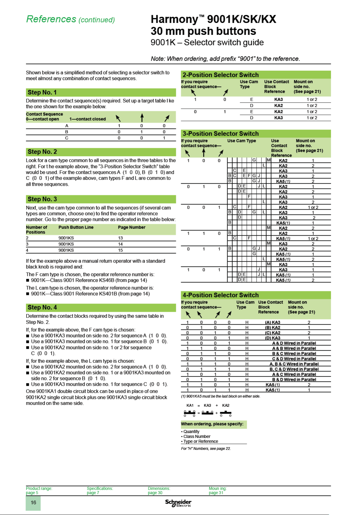
References
Harmony™ 9001K/SK/KX
30 mm push buttons
9001K – Push buttons and mushroom operators
Note: When ordering, add prex “9001” to the reference.
Non-Illuminated Momentary Push Button Operators
For use in hazardous locations, see page 23.
Contact blocks and legend plate not included unless otherwise noted.
Description Color Operator with 1 N.O.
Full Guard Black KR1BH13 KR1BH5 KR1BH6 KR1B
Red KR1RH13 KR1RH5 KR1RH6 KR1R
Green KR1GH13 KR1GH5 KR1GH6 KR1G
9001KR1B
No Guard Black KR3BH13 KR3BH5 KR3BH6 KR3B
9001KR3B
Extended Guard Black KR2BH13 KR2BH5 KR2BH6 KR2B
9001KR2B
1-3/8 in (35 mm)
Diameter
Mushroom Button
9001KR4B
1-1/2 in (40 mm)
Diameter
Mushroom Button
9001KR24BM
2-1/4 in (57 mm)
Diameter
Mushroom Button
9001KR5B
2-3/8 in (60 mm)
Diameter
Mushroom Button
9001KR25BM
(1) The universal push button operators contain one each of the following color inserts: black, red, green, yellow, orange, blue and white.
(2) Replace b with the color code as chosen from the color code table below.
(3) Knob has the words “Emergency Stop” in raised letters highlighted in white for readability.
(4) Replace d with the color code as chosen from the color code table below.
Universal (1) KR1UH13 KR1UH5 KR1UH6 KR1U
Other (2) KR1bH13 KR1bH5 KR1bH6 KR1b
Red KR3RH13 KR3RH5 KR3RH6 KR3R
Green KR3GH13 KR3GH5 KR3GH6 KR3G
Universal (1) KR3UH13 KR3UH5 KR3UH6 KR3U
Other (2) KR3bH13 KR3bH5 KR3bH6 KR3b
Red KR2RH13 KR2RH5 KR2RH6 KR2R
Green KR2GH13 KR2GH5 KR2GH6 KR2G
Universal (1) KR2UH13 KR2UH5 KR2UH6 KR2U
Other (2) KR2bH13 KR2bH5 KR2bH6 KR2b
Snap-In Plastic Mushroom Button
Black KR4BH13 KR4BH5 KR4BH6 KR4B
Red KR4RH13 KR4RH5 KR4RH6 KR4R
Red (3) KR4R05H13 KR4R05H5 KR4R05H6 KR4R05
Green KR4GH13 KR4GH5 KR4GH6 KR4G
Other (4) KR4dH13 KR4dH5 KR4dH6 KR4d
Screw-On Plastic Mushroom Button with Set Screw
Black KR24BH13 KR24BH5 KR24BH6 KR24B
Red KR24RH13 KR24RH5 KR24RH6 KR24R
Green KR24GH13 KR24GH5 KR24GH6 KR24G
Other (4) KR24dH13 KR24dH5 KR24dH6 KR24d
Screw-in Metal Mushroom Button with Set Screw
Black — — — KR24BM
Red — — — KR24RM
Green — — — KR24GM
Snap-In Plastic Mushroom Button
Black KR5BH13 KR5BH5 KR5BH6 KR5B
Red KR5RH13 KR5RH5 KR5RH6 KR5R
Red (3) KR5R05H13 KR5R05H5 KR5R05H6 KR5R05
Green KR5GH13 KR5GH5 KR5GH6 KR5G
Other (4) KR5dH13 KR5dH5 KR5dH6 KR5d
Screw-On Plastic Mushroom Button with Set Screw
Black KR25BH13 KR25BH5 KR25BH6 KR25B
Red KR25RH13 KR25RH5 KR25RH6 KR25R
Green KR25GH13 KR25GH5 KR25GH6 KR25G
Other (4) KR25dH13 KR25dH5 KR25dH6 KR25d
Screw-in Metal Mushroom Button with Set Screw
Black — — — KR25BM
Red — — — KR25RM
Green — — — KR25GM
and 1 N.C. Contact
(KA1)
Operator with
1 N.O. Contact (KA2)
Operator with
1 N.C. Contact (KA3)
Operator Only
with No Contacts
Color Codes
Color KR1, 2, 3
Blue
Yellow
White
Orange
Gray
To select and order Contact Blocks, Light Modules, Knobs, and
Accessories, see pages 20 to 29.
Product range:
page 5
Place Color Code
in Reference b
L
Y
W
S
E
KR4, 5, 24, 25
Place Color Code
in Reference d
L
Y
—
S
—
Specications:
page 7
Dimensions:
page 30
Moun ing:
page 31
11
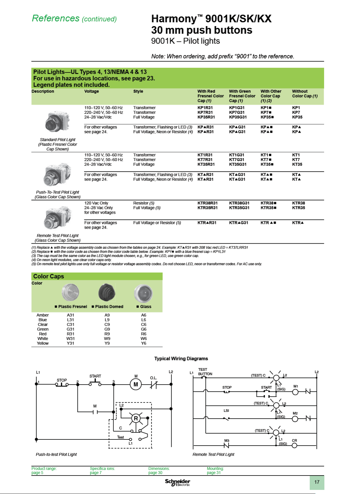
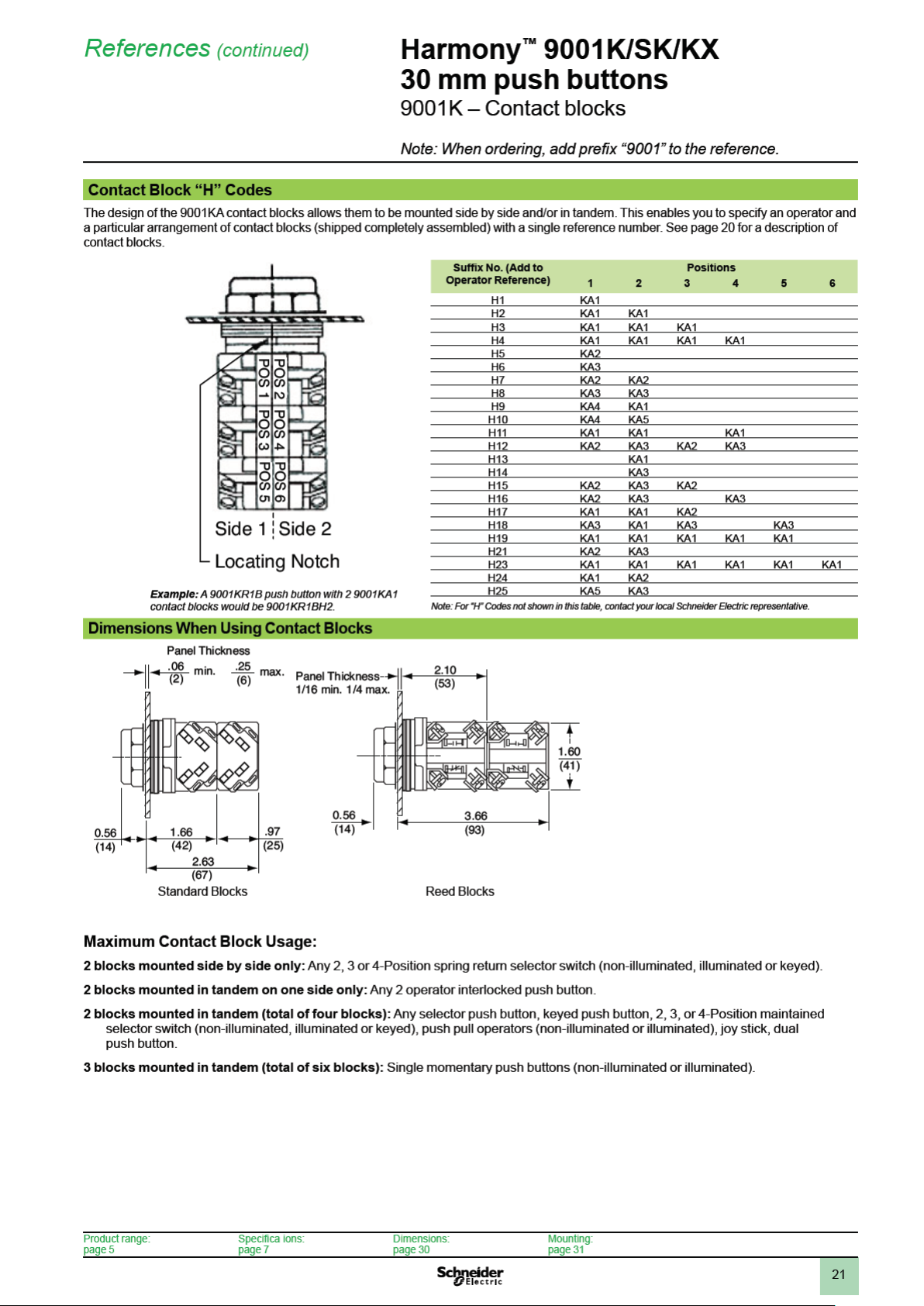
References (continued)
Harmony™ 9001K/SK/KX
30 mm push buttons
9001K – Push buttons and mushroom operators
Note: When ordering, add prex “9001” to the reference.
Illuminated Momentary Push Button Operators
For use in hazardous locations, see page 23.
Legend plate and contact block not included unless otherwise noted.
Description Voltage
Full Guard
Illuminated
Push Button
Clear Plas ic
Top
9001K1L1
Full Guard
Illuminated
Push Button
Metal Top
9001K3L1
No Guard
Illuminated
Push Button
9001K2L1
1-3/8 in
(35 mm)
Illuminated
Screw-On
Plastic
Mushroom
(no Set Screw)
9001K2LR20
2-1/4 in
(57 mm)
Illuminated
Screw-On
Plastic
Mushroom
(no Set Screw)
9001K2LR21
(1) These operators can be ordered complete with contact blocks. For maximum block usage, see page 22. Add the “H”
number chosen from page 22 to the end of the operator reference number and add the cost of the “H” number to the operator cost.
(2) Replace b with the voltage assembly code as chosen from the tables on page 24. Example: K2Lb with 240 Vac/Vdc = K2L25
(3) On neon light modules, use clear color caps only.
(4) The cap must be the same color as the LED light module chosen, e.g., for red LED, use red color cap.
(5) Replace e with the color code as chosen from the color cap table below. Example: K2L25e with a blue 13⁄8 mushroom button = K2L25L20
(6) The only difference between a no guard (K2L) operator and mushroom button operator is the color cap.
and
Frequency
110–120 V, 50–60 Hz Transformer K1L1RH13 K1L1GH13 K1L1e
220–240 V, 50–60 Hz Transformer K1L7RH13 K1L7GH13 K1L7e
24–28 Vac/Vdc Full Voltage K1L35RH13 K1L35GH13 K1L35e
For other voltages (2) Transformer or Flashing K1LbRH13 K1LbGH13 K1Lbe
110–120 V, 50–60 Hz Transformer K3L1RH13 K3L1GH13 K3L1e
220–240 V, 50–60 Hz Transformer K3L7RH13 K3L7GH13 K3L7e
24–28 Vac/Vdc Full Voltage K3L35RH13 K3L35GH13 K3L35e
For other voltages (2) Transformer or Flashing K3LbRH13 K3LbGH13 K3Lbe
110–120 V, 50–60 Hz Transformer K2L1RH13 K2L1GH13 K2L1e
220–240 V, 50–60 Hz Transformer K2L7RH13 K2L7GH13 K2L7e
24–28 Vac/Vdc Full Voltage K2L35RH13 K2L35GH13 K2L35e
For other voltages (2) Transformer or Flashing K2LbRH13 K2LbGH13 K2Lbe
110–120 V, 50–60 Hz Transformer K2L1R20H13 K2L1G20H13 Order K2Lbe above
220–240 V, 50–60 Hz Transformer K2L7R20H13 K2L7G20H13
24–28 Vac/Vdc Full Voltage K2L35R20H13 K2L35G20H13
For other voltages (2) Transformer or Flashing K2LbR20H13 K2LbG20H13
110–120 V, 50–60 Hz Transformer K2L1R21H13 K2L1G21H13 Order K2Lbe above
220–240 V, 50–60 Hz Transformer K2L7R21H13 K2L7G21H13
24–28 Vac/Vdc Full Voltage K2L35R21H13 K2L35G21H13
For other voltages (2) Transformer or Flashing K2LbR21H13 K2LbG21H13
Style With Red Color
Cap and 1 N.O.
and 1 N.C.
Contact (KA1) (2)
Full Voltage K1LbRH13 K1LbGH13 K1Lbe
Resistor or Neon (3) K1LbRH13 K1LbGH13 K1Lbe
LED (4) K1LbRH13 K1LbGH13 K1Lbe
Full Voltage K3LbRH13 K3LbGH13 K3Lbe
Resistor or Neon (3) K3LbRH13 K3LbGH13 K3Lbe
LED (4) K3LbRH13 K3LbGH13 K3Lbe
Full Voltage K2LbRH13 K2LbGH13 K2Lbe
Resistor or Neon (3) K2LbRH13 K2LbGH13 K2Lbe
LED (4) K2LbRH13 K2LbGH13 K2Lbe
Full Voltage K2LbR20H13 K2LbG20H13
Resistor or Neon (3) K2LbR20H13 K2LbG20H13
LED (4) K2LbR20H13 K2LbG20H13
Full Voltage K2LbR21H13 K2LbG21H13
Resistor or Neon (3) K2LbR21H13 K2LbG21H13
LED (4) K2LbR21H13 K2LbG21H13
With Green Color
Cap and 1 N.O.
and 1 N.C.
Contact (KA1) (2)
With Other Color
Cap Without
Contact Block
(1) (2) (5)
(6)
(6)
Color Caps
Color Color Codes
e K1L, K2L, K3L e 1-3/8 in
Red
Green
Blue
Yellow
White
Clear
Amber
To select and order Contact Blocks, Light Modules, Knobs, and Accessories, see pages 20 to 29.
Product range:
page 5
R
G
L
Y
W
C
A
Mushroom
R20
G20
L20
Y20
W20
C20
A20
Specica ions:
page 7
e 2-1/4 in
Mushroom
R21
G21
L21
Y21
W21
C21
A21
Dimensions:
page 30
Mounting:
page 31


19
Emergency Break-Glass
Operator 9001K15
Rocker Arm Operating Lever
9001K50
References (continued)
Time Delay Push Button
Push-on Push-off Module
9001K85
Illuminated and Non-Illuminated Dual Operators
Meets UL Type 13/NEMA 13 and UL Type 6/NEMA 6, which UL and NEMA consider an
equivalent to UL Type 4/NEMA 4. For use in hazardous locations, see page 23.
Legend plate and contact blocks not included unless otherwise noted.
Description Color With 2 N.O.
Momentary
Dual
Function
9001KR7U
9001KR11U
Momentary
Interlocked
Dual Function
Maintained
Interlocked
Dual Function
Description Color Contacts (KA1) Without
Both Buttons
Maintained Interlocked
Assembly
One Button Momentary
One Button Maintained
Interlocked Assembly
(1) Universal for KR6, KR67, KR7 includes 2 inserts each of black, red and green.
(2) Replace b with one color for each button. R = red, G = green, B = Black. Example: A KR6 with left button red and right button black = KR6RB
(3) Universal for KR11, KR12 includes 2 each of black, red, green, yellow, orange, blue, white.
(4) Replace d with one color for each button. B = black, R = red, G = green, L = blue, Y = yellow, W = white, S = orange, E = gray.
Example: A KR11 with top button gray and bottom button orange = KR11ES
Harmony™ 9001K/SK/KX
30 mm push buttons
9001K – Specialty operators
Note: When ordering, add prex “9001” to the reference.
Universal (1)
Green-Red
Other (2)
Universal (1)
Green-Red
Other (2)
Universal (1)
Green-Red
Other (2)
Universal (3)
Other (4)
Universal (3)
Other (4)
Contacts (2 KA2)
KR6UH7
KR6GRH7
KR6bH7
KR67UH7
KR67GRH7
KR67bH7
KR7UH7
KR7GRH7
KR7bH7
— KR11UH1
— KR12UH1H1
With 1 N.O. &
1 N.C. Contact
(KA2, KA3)
KR6UH37
KR6GRH37
KR6bH37
KR67UH37
KR67GRH37
KR67bH37
KR7UH37
KR7GRH37
KR7bH37
KR11dH1
KR12dH1H1
Without
Contacts
KR6U
KR6GR
KR6b
KR67U
KR67GR
KR67b
KR7U
KR7GR
KR7b
Contacts
KR11U
KR11d
KR12U
KR12d
Emergency Break-Glass
Operator— UL 4, 13/NEMA 4, 13
Reference
K15
Operator is held in a depressed position by a
glass disc. When the glass disc is broken with the
hammer, button returns to a normal extended
position. Package of 5 discs included with
operator.
Rocker Arm Operating Lever
Reference
K50
Allows two standard push buttons to be operated
independently of each other. Order push buttons
and legend plates from pages 10, 11, 25, and 26
(please specify which marking is to be inverted).
9001K15 Replacement Parts
Description Reference
Yellow bumper 3105211101
Hammer and chain 3105206750
Lower ring nut 6512232801
Top ring nut 9001K40
Package of 5 replacement discs 9001K57
Clip to hold hammer 2540902240
Alternate Action—Push-on, Push-off Module
Reference
K85
Wobble stick
For easy operation of any
standard push button.
Reference
K8
Time Delay Push Button—UL Types 4, 13/NEMA 4, 13
Description
(Off - Delay)
Timed Contact
1 N.O. and 1 N.C.
Reference (All Colors)
Full Guard Extended Guard No Guard
KRD1UH1 KRD2UH1 KRD3UH1
KRD1UH2 KRD2UH2 KRD3UH2
This module can be added to standard 9001K,
9001KX, 9001SK or 9001T momentary push
button operators. Contact blocks mounted
behind this module (maximum of 2) are held in
the depressed position when the operator is
pressed once, and released to their normal
position when the operator is pressed again.
For a N.C. circuit, use a 9001KA3 or the N.C.
contact of either a 9001KA1 or 9001KA4. For a
N.O. circuit, use the N.O. contact of either a
9001KA4 or 9001KA6.
Product range:
page 5
Timed Contact
2 N.O. and 2 N.C.
Timing period is adjustable from 0.1 second to 60 seconds and begins after button has been released. Devices include a pack of
seven color inserts for color coding the push button. See page 28 for Universal color insert. Contacts are quick make-quick break.
Note: When mounted in top or bottom hole of a 9001K enclosure, device requires one additional space below or above operator.
When mounted other than in top or bottom hole, device may require two additional spaces, one above and one below operator.
Closing plates must be installed on unused holes.
Specica ions:
page 7
Dimensions:
page 30
Mounting:
page 31


27
KU1
KU17
KU37
KU27
References (continued)
Harmony™ 9001K/SK/KX
30 mm push buttons
9001K – Accessories
Note: When ordering, add prex “9001” to the reference.
Padlock Attachments
Used On Description Reference
Non-illuminated
push button —
Standard or
mushroom (KR4,
KR5 mushroom
buttons only).
Non-illuminated
push buttons with or
without protective
boots.
Non-illuminated
push buttons with or
without protective
boots.
Non-illuminated
push buttons, cover
type attachment.
KR, SKR
Push buttons, cover
type attachment.
Push-pull operator
and illuminated push
buttons. KR8, KR9
Holds button in
depressed position
and can be
padlocked.
Holds button in
depressed position
when padlocked.
Holds button in
depressed position
when padlocked.
Attachment can be
padlocked. Does not
hold button in
depressed position.
Spring loaded cover
cannot be
padlocked. Does not
hold button in
depressed position.
Holds button in
depressed position
and can be
padlocked.
K4
K5
K97
K6
K60
K62
Padlock Attachments
Used On Description Reference
Selector switches
and potentiometers
(will not work with
gloved-hand knob).
Selector switches
and potentiometers
(will not work with
gloved-hand knob).
Illuminated push
buttons (with or
without guard) and
key operated push
buttons.
Illuminated push
buttons (with or
without guard) and
key operated push
buttons.
Maintained
push-pull operators
using 1.375 in dia.
mushroom buttons
(-20 series as shown
on page 28).
Cover type
attachment that can
be padlocked to
keep unauthorized
personnel from
tampering with the
operator.
Same as 9001K7
but with spring
loaded lockout
cover.
Cover type
attachment that can
be padlocked to
keep unauthorized
personnel from
tampering with the
operator.
Same as 9001K108
but with spring
loaded lockout
cover.
Cover type
attachment that
holds mushroom
button in depressed
position and can be
padlocked.
K7
K107
K108
K109
K110
Protective Boots
KR11U and KR12U
Interlocked
Assembly
9001KR9
Push-pull
operators—
Non-Illuminated
and Illuminated
Holds maintained
button in depressed
position and can be
padlocked.
Holds button in
depressed position.
Can be padlocked.
K96
K162
Mushroom Button Guards
Aluminum Mushroom Guard
for 1.375 in Mushroom Button
Operator (KR4, KR24)
Reference Reference Used On Reference Used On
K48 K56a (1) KR4 K68 KR5
(1) Replace a with B=Black, G=Green, R=Red or Y=Yellow.
(2) Replace b with R=Red or Y=Yellow. The mushroom guard has nger holes for
push-pull operators.
Product range:
page 5
Yellow Plastic Extended
Mushroom Guard for 1.375 in
and 1.625 in Mushroom
Button Operators
K56bM (2) KR8, KR9 K685 KR25
Specica ions:
page 7
Aluminum Mushroom Guard
for 2.25 in Mushroom Button
Operator
Dimensions:
page 30
These 9001KU protective boots are recommended for very dirty environments or severe hose
down, but they are not required for UL Type 4 rating on the 9001K operators. The 9001K1
wrench (see page 29) is required for installation of these boots.
For Non-Illuminated
Push Buttons (3)
Color Reference Standard knob selector switch KU17
Black KU1 Gloved-hand cap for use on standard
Red KU2
Blue KU3
Brown KU4 Standard pilot light and maintained
Green KU5
Yellow KU6
Clear KU7 Push-to-test and illuminated push
Clear KU8
(Provides Full Guard) Illuminated push button with guard KU47
(3) Use KU27 for maintained contact push buttons.
Clear Color for Reference
KU18
knob selector switch
KU27
contact push buttons
KU37
button without guard
Closing Plates
Round (1-1/2 in Dia.)
Description Reference
Gray K51 (4)
Black K52 (4)
(4) Meets UL and NEMA 1, 2, 3, 4, 4X, 6, 12 and 13.
Mounting:
page 31


29
References (continued)
Harmony™ 9001K/SK/KX
30 mm push buttons
9001K – Replacement parts
Ring Nuts
Used On Reference
K1L 9001K44
K30-K37 9001K45
K70-K73 9001K45
K20, K21, K22, K23 9001K45
K20, K21, K22, K23 (1) 9001K46
K2L 9001K49
K3L (complete) 9001K111
K3L (metal top only) 6515802701
KP, KTR 9001K41
KR1 9001K41
KR11 9001K42
KR12 (1) 9001K42
KR12 (2) 9001K41
KR13, 14, 15 9001K55
KR2 9001K42
KR20 9001K49
KR24 9001K49
KR25 9001K49
KR3 9001K40
KR4 9001K41
KR5 9001K41
KR6 9001K47
KR67 9001K47
KR7 9001K47
KR8 9001K58
KR9 9001K41
KS 9001K45
KS (3) 9001K46
KT 9001K49
(1) Maintained button of two button operator.
(2) Momentary button of two button operator.
(3) Secondary ring nut (holds knob on selector switch or potentiometer).
Replacement Lamps For Series A–F (black)
Light Modules
Light
Module Reference
KM1 GE44 (4) —
KM2 GE1490 2550101003
KM3 GE44 (4) —
KM4 GE1490 2550101003
KM5 GE44 (4) —
KM6 GE44 (4) —
KM7 GE44 (4) —
KM8 GE44 (4) —
KM9 GE755 2550101020
KM11 CMDK1A5 2550105014
KM12 CMDK1A5 2550105014
KM13 CMDK1A5 2550105014
KM14 CMDK1A5 2550105014
KM15 CMDK1A5 2550105014
KM21 SYL12PSB 2550105003
KM22 SYL12PSB 2550105003
KM23 SYL28PSB 2550105008
KM25 SYL120PSB 2550105005
KM31 SYL6PSB 2550105007
KM32 SYL12PSB 2550105003
KM34 SYL24PSB 2550105004
KM35 SYL28PSB 2550105008
KM36 SYL48PSB 2550105009
KM37 SYL60PSB 2550105010
KM38 SYL120PSB 2550105005
(4) GE44 and GE755 are interchangeable (GE755 gives longer life). If a GE44 lamp is
ordered, a GE755 (2550101020) will be substituted. For a replacement lamp in a current
series light module see the light module listing on page 24.
Product range:
page 5
Lamp Number
(ANSI)
Specica ions:
page 7
Schneider Electric
Replacement Lamp Reference
Dimensions:
page 30
Repair Parts
Description Reference
E10 Key
Gray cap for KR11 or KR12
Clear plas ic top (only) for 9001K44 Ring Nut
Gasket for 9001K Push-pull Knob
Gasket for Plastic Illuminated Lens
Gasket for 9001K selector switch knob
Black Compensating Gasket (9001K Operators)
Liner for Non-Illuminated Operators
Locking Thrust Washer
Nylon Spacer
Push-pull Mushroom Adapter (5)
Rubber Boot for Joystick
Knob on Joysticks without latch
Knob for SK Potentiometer
Fingersafe Cover for 9001KM
(5) Allows Type -20 and -21 mushroom color caps to be used on push-pull operators. Use of
9001K54 voids Type 6 rating.
2941101100
3105217001
4487D63XI
6509701801
6509701901
3105406401
6509702001
6509704901
6512231201
6509705001
9001K54
6512243201
4458D20X3
3105404408
6508804101
KU Replacement Ring Nuts
(Threaded Inside and Out)
Used On Reference
KU1 through KU8, KU27, KU37, KU47 3105204101
KU17, KU18 3105205901
Interlock
For mechanically interlocking two push buttons so that only one
button can be depressed at a time. A K3 attachment is
furnished with the 9001KR11 and KR12 operators. However,
these are maintained operators and the K3 interlock serves to
release one of the buttons when the other is depressed. When
used with momentary contact buttons, the K3 interlock does
not hold the buttons in the depressed position. It simply
prevents pushing both buttons at the same time.
The K3 interlock is mounted behind the operators. Operators
not included.
Reference
9001K3
Screwdriver
Reference
9001K69
Used to tighten mounting screws on contact blocks and light modules.
Wrenches
K95 K1
Where Used Reference
For tightening ring nuts on 22 and 30 mm control units 9001K95
For protective cap kits 9001K1
Mounting:
page 31


39
Specications (continued)
Harmony™ 9001K/SK/KX
30 mm push buttons
9001SK
Basic Operators
(For Color Caps, Mushroom Buttons, Knobs, Se lector Switch Cams, Contact Blocks, Light Modules and Legend Plates, see page 51.)
Description UL Types/NEMA Types
4, 4X, 13
Non Illuminated Push Button (Full Guard) 9001SKR1
Non Illuminated Push Button (Extended Guard) 9001SKR2
Non Illuminated Push Button (No Guard) 9001SKR3
Non Illuminated Push Button (Mushroom Button/screw on) 9001SKR20
Non Illuminated Dual Push Button (Momentary) –
Non Illuminated Dual Push Button (Momentary Interlocked) –
Non Illuminated Dual Push Button (Maintained Interlocked) –
Momentary Pull - Maintained Neutral - Momentary Push 9001SKR8 (1)
Maintained Pull - Maintained Push 9001SKR9 (1)
Illuminated Push Button (Full Guard - Plastic Top) 9001SK1L (2)
Illuminated Push Button and Push-to-test (No Guard) 9001SK2L (2) (3)
Illuminated Push Button (Full Guard - Metal Top) –
Standard Pilot Light 9001SKP
2-Position Selector Switch 9001SKS1 (1), 9001SKS2 (1), 9001SKS3 (1)
3-Position Selector Switch 9001SKS4 (1), 9001SKS5 (1), 9001SKS6 (1), 9001SKS7 (1)
4-Position Selector Switch 9001SKS8 (1)
Trigger-Action Emergency Stop 9001SKR16 (1)
(1) Operator can be converted to an illuminated operator by removing the liner (6509704901) and adding a light module.
(2) Operator can be converted to a non-illuminated operator by adding liner (6509704901).
(3) Operator includes jumper wires for push-to-test conversion.
Non Hazardous Locations:
File
CCN
E42259
NKCR
File
Class
LR25490
3211 03
Marking
Hazardous Locations (Reed contact blocks, see page 53):
File
CCN
E10054
NOIV
File
Class
LR26817
3218 02
Marking
Product range:
page 36
References:
page 41
Dimensions:
page 60
Mounting:
page 61

40
Specications (continued)
Harmony™ 9001K/SK/KX
30 mm push buttons
9001SK
9001SK Operator Materials:
Push Button and Push-to-test Pilot Light
(9001SKR and 9001SKT)
Base – Thermoplastic Polyester
Stem – Acetal (non-illuminated push button)
Thermoplastic Polyester (illuminated push button
and push-to-test pilot light)
Seal – Nitrile
Gasket – Nitrile
Spring – 302 Stainless Steel
Spring Support – CRS
Lock Ring – Nylon
Trim Washer – Polypropylene
Locking Thrust Washer – Thermoplastic Polyester
Ring Nut – Thermoplastic Polyester
Color Insert – Polyethylene (non-illuminated push button)
Color Cap – Polycarbonate (illuminated push button and
push-to-test pilot light)
Mushroom Button – Acetal (non-illuminated push button)
Polycarbonate (illuminated push button)
Liner – Polypropylene (non-illuminated push button)
Selector Switch (9001SKS)
Base – Thermoplastic Polyester
Seal – Nitrile
Gasket – Nitrile
Seal Keeper – 302 Stainless Steel
Spring – 302 Stainless Steel
Cam Follower – Delrin 100
Bearing Washer – Polyester Film
Cam Carrier – Trogamid
Cam Prole – Delrin 100
Liner – Polypropylene (non-illuminated only)
Knob – Polycarbonate
Trim Washer – Polypropylene
Locking Thrust Washer – Thermoplastic Polyester
Spring Support – CRS
Pilot Light (9001SKP)
Gasket – Nitrile
Base – Thermoplastic Polyester
Trim Washer – Polypropylene
Locking Thrust Washer – Thermoplastic Polyester
Ring Nut – Thermoplastic Polyester
Color Cap – Polycarbonate
Contact Block And Light Module Materials:
Contact Block (9001KA)
Housing – Amorphous Nylon
Contact Slider – Phenolic, Nylon or Acetal
Terminal – Steel
Saddle Clamp – Steel
Spring – Stainless Steel
Contacts – Silver and Copper
Blade – Beryllium Copper
Mounting Screw – Steel
Label – Paper
Light Module (9001KM)
Housing – Thermoplastic Polyester
Socket – Steel
Terminal – Steel with Tin Plate
Saddle Clamp – Steel
Translating Pin – Polycarbonate
Transformer – Thermoplastic Polyester, Steel, Copper,
Polyvinyl Chloride, Polytetrauorethylene,
Acetate, Paper
Lamp Spring – Tin Plated Music Wire
Product range:
page 36
References:
page 41
Dimensions:
page 60
Moun ing:
page 61

41
References (continued)
Harmony™ 9001K/SK/KX
30 mm push buttons
9001SK – Push buttons and mushroom operators
Note: When ordering, add prex “9001” to the reference.
Non-Illuminated Momentary Push Button Operators—UL Types 4, 4X, 13/NEMA 4, 4X, 13
For use in hazardous locations, see page 53.
Contact blocks and legend plate not included unless otherwise noted.
Description Color Operator with
Black SKR1BH13 SKR1BH5 SKR1BH6 SKR1B
Red SKR1RH13 SKR1RH5 SKR1RH6 SKR1R
Green SKR1GH13 SKR1GH5 SKR1GH6 SKR1G
Universal (1) SKR1UH13 SKR1UH5 SKR1UH6 SKR1U
9001SKR1B
Full Guard
9001SKR3B
No Guard
9001SKR2B
Extended Guard
9001SKR4B
1-3/8 in (35 mm)
Mushroom Button
9001SKR5
2-1/4 in (57 mm)
Mushroom Button
Other (2) SKR1bH13 SKR1bH5 SKR1bH6 SKR1b
Black SKR3BH13 SKR3BH5 SKR3BH6 SKR3B
Red SKR3RH13 SKR3RH5 SKR3RH6 SKR3R
Green SKR3GH13 SKR3GH5 SKR3GH6 SKR3G
Universal (1) SKR3UH13 SKR3UH5 SKR3UH6 SKR3U
Other (2) SKR3bH13 SKR3bH5 SKR3bH6 SKR3b
Black SKR2BH13 SKR2BH5 SKR2BH6 SKR2B
Red SKR2RH13 SKR2RH5 SKR2RH6 SKR2R
Green SKR2GH13 SKR2GH5 SKR2GH6 SKR2G
Universal (1) SKR2UH13 SKR2UH5 SKR2UH6 SKR2U
Other (2) SKR2b SKR2bH5 SKR2bH6 SKR2b
Snap-In Mushroom Button
Black SKR4BH13 SKR4BH5 SKR4BH6 SKR4B
Red SKR4RH13 SKR4RH5 SKR4RH6 SKR4R
Red (3) SKR4R05H13 SKR4R05H5 SKR4R05H6 SKR4R05
Green SKR4GH13 SKR4GH5 SKR4GH6 SKR4G
Other (4) SKR4dH13 SKR4dH5 SKR4dH6 SKR4d
Screw-On Mushroom Button with Set Screw Security
Black SKR24BH13 SKR24BH5 SKR24BH6 SKR24B
Red SKR24RH13 SKR24RH5 SKR24RH6 SKR24R
Green SKR24GH13 SKR24GH5 SKR24GH6 SKR24G
Other (4) SKR24dH13 SKR24dH5 SKR24dH6 SKR24d
Snap-In Mushroom Button
Black SKR5BH13 SKR5BH5 SKR5BH6 SKR5B
Red SKR5RH13 SKR5RH5 SKR5RH6 SKR5R
Red (3) SKR5R05H13 SKR5R05H5 SKR5R05H6 SKR5R05
Green SKR5GH13 SKR5GH5 SKR5GH6 SKR5G
Other (4) SKR5dH13 SKR5dH5 SKR5dH6 SKR5d
Screw-On Mushroom Button with Set Screw Security
Black SKR25BH13 SKR25BH5 SKR25BH6 SKR25B
Red SKR25RH13 SKR25RH5 SKR25RH6 SKR25R
Green SKR25GH13 SKR25GH5 SKR25GH6 SKR25G
Other (4) SKR25dH13 SKR25dH5 SKR25dH6 SKR25d
1 N.O. and
1 N.C. Contact
(KA1)
Operator with
1 N.O. Contact
(KA2)
Operator with
1 N.C. Contact
(KA3)
Operator Only
No Contacts (5)
Color Codes
Color b SKR1, 2, 3 Place Color Code in Reference d SKR4, 5, 24, 25 Place Color Code in Reference
Blue L L
Yellow Y Y
White W —
Orange S S
Gray E —
(1) The universal push button operators contain one each of the following color inserts: black, red, green, yellow, orange, blue and white.
(2) Replace b with the color code as chosen from the color code table above.
(3) Knob has the words “Emergency Stop” in raised letters highlighted in white for readability.
(4) Replace d with the color code as chosen from the color code table above
(5) These operators can be ordered complete with contact blocks. For maximum block usage, see page 51. Add the “H” number chosen from
page 51 to the end of the operator reference number and add the cost of the “H” number to the operator cost.
To select and order Contact Blocks, Light Modules, Knobs, and Accessories, see pages 50 to 59.
Product range:
page 36
Specica ions:
page 38
Dimensions:
page 60
Mounting:
page 61

42
References (continued)
Illuminated Push Button Operators—UL Types 4, 4X, 13/NEMA 4, 4X, 13
For use in hazardous locations, see page 53.
Legend plate not included unless otherwise noted.
Description Voltage and
Full Guard
Illuminated
Push Button
9001SK1L1
Harmony™ 9001K/SK/KX
30 mm push buttons
9001SK – Push buttons and mushroom operators
Note: When ordering, add prex “9001” to the reference.
Frequency
110–120 V, 50–60 Hz Transformer SK1L1RH13 SK1L1GH13 SK1L1
220–240 V, 50–60 Hz Transformer SK1L7RH13 SK1L7GH13 SK1L7
24–28 Vac/Vdc Full Voltage SK1L35RH13 SK1L35GH13 SK1L35
For other voltages (2) Transformer, Flashing SK1LbRH13 SK1LbGH13 SK1Le
Style With Red Color
Cap and 1 N.O.
and 1 N.C.
Contact (KA1)
Full Voltage SK1LbRH13 SK1LbGH13 SK1Le
Resistor, Neon (3) SK1LbRH13 SK1LbGH13 SK1Le
LED SK1LbRH13 SK1LbGH13 SK1Le (4)
With Green
Color Cap and
1 N.O.and 1 N.C.
Contact (KA1)
With Other
Color Cap
Without
Contact
Blocks (1) (5)
9001SK2L1
9001SK2L1R20
9001SK2L1R21
No Guard
Illuminated
Push Button
1-3/8 in
(35 mm)
Illuminated
Mushroom
2-1/4 in
(57 mm)
Illuminated
Mushroom
(1) These operators can be ordered complete with contact blocks. For maximum block usage, see page 51. Add the “H” number chosen from
page 51 to the end of the operator reference number and add the cost of the “H” number to the operator cost.
(2) Replace b with the voltage assembly code as chosen from the tables on page 54. EXAMPLE: SK2Lb with 240 Vac/Vdc = SK2L25.
(3) On neon light modules, use clear color caps only.
(4) The cap must be the same color as the LED light module chosen e.g., for red LED, use red color cap.
(5) Replace e with the color code as chosen from the color code table below. EXAMPLE: SK2L35e with a blue 1-3/8 in mushroom button =
SK2L35L20.
(6) The only difference between a no guard (SK2L) operator and mushroom button operator is the color cap.
110–120 V, 50–60 Hz Transformer SK2L1RH13 SK2L1GH13 SK2L1
220–240 V, 50–60 Hz Transformer SK2L7RH13 SK2L7GH13 SK2L7
24–28 Vac/Vdc Full Voltage SK2L35RH13 SK2L35GH13 SK2L35
For other voltages (2) Transformer, Flashing SK2LbRH13 SK2LbGH13 SK2Le
Full Voltage SK2LbRH13 SK2LbGH13 SK2Le
Resistor, Neon (3) SK2LbRH13 SK2LbGH13 SK2Le
LED SK2LbRH13 SK2LbGH13 SK2Le (4)
110–120 V, 50–60 Hz Transformer SK2L1R20H13 SK2L1G20H13 Order
220–240 V, 50–60 Hz Transformer SK2L7R20H13 SK2L7G20H13
24–28 Vac/Vdc Full Voltage SK2L35R20H13 SK2L35G20H13
For other voltages (2) Transformer, Flashing SK2LbR20H13 SK2LbG20H13
Full Voltage SK2LbR20H13 SK2LbG20H13
Resistor, Neon (3) SK2LbR20H13 SK2LbG20H13
LED SK2LbR20H13 SK2LbG20H13
110–120 V, 50–60 Hz Transformer SK2L1R21H13 SK2L1G21H13 Order
220–240 V, 50–60 Hz Transformer SK2L7R21H13 SK2L7G21H13
24–28 Vac/Vdc Full Voltage SK2L35R21H13 SK2L35G21H13
For other voltages (2) Transformer, Flashing SK2LbR21H13 SK2LbG21H13
Full Voltage SK2LbR21H13 SK2LbG21H13
Resistor, Neon (3) SK2LbR21H13 SK2LbG21H13
LED SK2LbR21H13 SK2LbG21H13
SK2Le (4) (6)
SK2Le (4) (6)
Product range:
page 36
Color Caps
Color Color Codes
SK1L/SK2L 1-3/8 in (35 mm) Mushroom 2-1/4 in (57 mm) Mushroom
Red R R20 R21
Green G G20 G21
Blue L L20 L21
Yellow Y Y20 Y21
White W W20 W21
Clear C C20 C21
Amber A A20 A21
To select and order Contact Blocks, Light Modules, Knobs, and Accessories, see pages 50 to 59.
Specications:
page 38
Dimensions:
page 60
Moun ing:
page 61


49
References (continued)
Specialty Operators—UL Types 4, 4X, 13/NEMA 4, 4X, 13
For use in hazardous locations, see page 53.
Legend plate and contact blocks not included unless otherwise noted.
Interlocked Assembly Description Color Contacts Without Contacts
9001SKR11U
(1) Universal for SKR11,12 includes 2 each of black, red, green, yellow, orange, blue, white.
(2) Replace b with the color code as chosen from the following: B = black, R = red, G = green, L = blue, Y = yellow, W = white, S = orange, E = gray.
Example: An SKR11 with top button gray and bottom button orange = SKR11ES
Harmony™ 9001K/SK/KX
30 mm push buttons
9001SK – Specialty operators
Note: When ordering, add prex “9001” to the reference.
Interlocked Assembly
Both Buttons Maintained
Interlocked Assembly
One Button Momentary
Interlocked Assembly
One Button Maintained
Universal (1) SKR11UH1 SKR11U
Other (2) SKR11bH1 SKR11b
Universal (1) SKR12UH1H1 SKR12U
Other (2) SKR12bH1H1 SKR12b
Product range:
page 36
Specica ions:
page 38
Dimensions:
page 60
Mounting:
page 61


57
KU1
KU17
KU37
KU27
References (continued)
Harmony™ 9001K/SK/KX
30 mm push buttons
9001SK – Accessories
Note: When ordering, add prex “9001” to the reference.
Padlock Attachments
Used On Description Reference
Non-illuminated
push button —
Standard or
mushroom (KR4,
KR5 mushroom
buttons only).
Non-illuminated
push buttons with
or without
protective boots.
Non-illuminated
push buttons with
or without
protective boots.
Non-illuminated
push buttons,
cover type
attachment. KR,
SKR
Push buttons,
cover type
attachment.
Push-pull operator
and illuminated
push buttons. KR8,
KR9
Holds button in
depressed position
and can be
padlocked.
Holds button in
depressed position
when padlocked.
Holds button in
depressed position
when padlocked.
Attachment can be
padlocked. Does
not hold button in
depressed position.
Spring loaded
cover cannot be
padlocked. Does
not hold button in
depressed position.
Holds button in
depressed position
and can be
padlocked.
K4
K5
K97
K6
K60
K62
Padlock Attachments
Used On Description Reference
Selector switches
and potentiometers
(will not work with
gloved-hand knob).
Selector switches
and potentiometers
(will not work with
gloved-hand knob).
Illuminated push
buttons (with or
without guard) and
key operated push
buttons.
Illuminated push
buttons (with or
without guard) and
key operated push
buttons.
Maintained
push-pull operators
using 1.375 in dia.
mushroom buttons
(-20 series as
shown on page 58).
Cover type
attachment that can
be padlocked to
keep unauthorized
personnel from
tampering with the
operator.
Same as 9001K7
but with spring
loaded lockout
cover.
Cover type
attachment that can
be padlocked to
keep unauthorized
personnel from
tampering with the
operator.
Same as 9001K108
but with spring
loaded lockout
cover.
Cover type
attachment that
holds mushroom
button in depressed
posi ion and can be
padlocked.
K7
K107
K108
K109
K110
Protective Boots
KR11U and
KR12U
Interlocked
Assembly
9001SKR9
Push-pull
operators—
Non-Illuminated
and Illuminated
Holds maintained
button in
depressed position
and can be
padlocked.
Holds button in
depressed position.
Can be padlocked.
Mushroom Button Guards
Aluminum Mushroom Guard
for 1.375 in Mushroom Button
Operator (KR4, KR24)
Reference Reference Used On
K48 K56a (1) SKR4
(1) Replace a with B=Black, G=Green, R=Red or Y=Yellow.
(2) Replace b with R=Red or Y=Yellow. The mushroom guard has nger holes for
push-pull operators.
Product range:
page 36
Yellow Plastic Extended
Mushroom Guard for 1.375 in
and 1.625 in Mushroom
Button Operators
K56bM (2) SKR8, SKR9
Specica ions:
page 38
Aluminum Mushroom Guard
for 2.25 in Mushroom Button
Operator
Dimensions:
page 60
K96
K162
These 9001KU protective boots are recommended for very dirty environments or severe
hose down, but they are not required for UL Type 4 or 4X rating on the 9001SK operators.
The 9001K1 wrench (see page 59) is required for installation of these boots.
For Non-Illuminated
Push Buttons (3)
Color Reference Standard knob selector switch KU17
Black KU1 Gloved-hand cap for use on standard
Red KU2
Blue KU3
Brown KU4 Standard pilot light and maintained
Green KU5
Yellow KU6
Clear KU7 Push-to-test and illuminated push
Clear KU8
(Provides Full Guard) Illuminated push button with guard KU47
(3) Use KU27 for maintained contact push buttons.
Clear Color for Reference
KU18
knob selector switch
KU27
contact push buttons
KU37
button without guard
Closing Plates
Round (1-1/2 in Dia.)
Description Reference
Gray K51 (4)
Black K52 (4)
(4) Meets UL and NEMA 1, 2, 3, 4, 4X, 6, 12 and 13.
Mounting:
page 61


59
References (continued)
Harmony™ 9001K/SK/KX
30 mm push buttons
9001SK – Replacement parts
Ring Nuts
Used On Reference
SK1L 9001SK44
— —
— —
SK20, SK21, SK22, SK23 9001SK45
SK20, SK21, SK22, SK23 (3) 9001SK46
SK2L 9001SK49
— —
— —
SKP, SKTR 9001SK41
SKR1 9001SK41
SKR11 9001SK42
SKR12 (1) 9001SK42
SKR12 (2) 9001SK41
— —
SKR2 9001SK42
— —
— —
SKR25 9001SK49
SKR3 9001SK40
SKR4 9001SK41
SKR5 9001SK41
— —
— —
— —
SKR8 6509704401
SKR9 9001SK41
SKS 9001SK45
SKS (3)
SKRU11
SKRU1,2,3,4,5,10
SKT 9001SK49
(1) Maintained button of two button operator.
(2) Momentary button of two button operator.
(3) Secondary ring nut (holds knob on selector switch or potentiometer).
9001SK46
9001SK41
9001SK40
Replacement Lamps For Series A–F (black)
Light Modules
Light
Module Reference
KM1 GE44 (4) —
KM2 GE1490 2550101003
KM3 GE44 (4) —
KM4 GE1490 2550101003
KM5 GE44 (4) —
KM6 GE44 (4) —
KM7 GE44 (4) —
KM8 GE44 (4) —
KM9 GE755 2550101020
KM11 CMDK1A5 2550105014
KM12 CMDK1A5 2550105014
KM13 CMDK1A5 2550105014
KM14 CMDK1A5 2550105014
KM15 CMDK1A5 2550105014
KM21 SYL12PSB 2550105003
KM22 SYL12PSB 2550105003
KM23 SYL28PSB 2550105008
KM25 SYL120PSB 2550105005
KM31 SYL6PSB 2550105007
KM32 SYL12PSB 2550105003
KM34 SYL24PSB 2550105004
KM35 SYL28PSB 2550105008
KM36 SYL48PSB 2550105009
KM37 SYL60PSB 2550105010
KM38 SYL120PSB 2550105005
(4) GE44 and GE755 are interchangeable (GE755 gives longer life). If a GE44 lamp is
ordered, a GE755 (2550101020) will be substituted. For a replacement lamp in a current
series light module see the light module listing on page 54.
Product range:
page 36
Lamp Number
(ANSI)
Specica ions:
page 38
Schneider Electric
Replacement Lamp Reference
Dimensions:
page 60
Repair Parts
Description Reference
E10 Key
Gray cap for 9001SKR11, or 9001SKR12
Clear plas ic top (only) for 9001SK44 Ring Nut
Gasket for 9001K and 9001SK Push-pull Knob
Gasket for Plastic Illuminated Lens
Gasket for 9001SK selector switch knob
Black Compensating Gasket
Liner for Non-Illuminated Operators
Locking Thrust Washer
Nylon Spacer
Locking Thrust Washer (Std. 9001SK Operator)
Push-pull Mushroom Adapter (5)
Rubber Boot for Joystick
Knob on Joysticks without latch
Knob for SK Potentiometer
Fingersafe Cover for 9001KM
(5) Allows Type -20 and -21 mushroom color caps to be used on push-pull operators. Use of
9001K54 voids Type 6 rating.
2941101100
3105217001
4487D63XI
6509701801
6509701901
3105406401
6509702001
6509704901
6512231201
6509705001
6512240601
9001K54
6512243201
4458D20X3
3105404408
6508804101
KU Replacement Ring Nuts
(Threaded Inside and Out)
Used On Reference
KU1 through KU8, KU27, KU37, KU47 3105204101
KU17, KU18 3105205901
Interlock
For mechanically interlocking two push buttons so that only one
button can be depressed at a time. A K3 attachment is
furnished with the 9001SKR11,SKR12, SKRU1 and SKRU11
operators. However, these are maintained operators and the
K3 interlock serves to release one of the buttons when the
other is depressed. When used with momentary contact
buttons, the K3 interlock does not hold the buttons in the
depressed position. It simply prevents pushing both buttons at
the same time.
The K3 interlock is mounted behind the operators. Operators
not included.
Reference
9001K3
Screwdriver
Reference
9001K69
Used to tighten mounting screws on contact blocks and light modules.
Wrenches
K95 K1
Where Used Reference
For tightening ring nuts on 22 and 30 mm control units 9001K95
For protective cap kits 9001K1
Mounting:
page 61


69
Specications (continued)
Harmony™ 9001K/SK/KX
30 mm push buttons
9001KX
9001KX Operator Materials
Single Push Button (KXRA, KXRB, KXRN, KXRP, KXTA)
Gasket – Nitrile
Locking Head – ZAMAC #3
Screws – Steel
Terminals – Steel
Button – Polycarbonate
Seal – Nitrile
Seal Retainer – Steel
Bezel – Zinc
Stem – Polycarbonate
Stem Cover – Polycarbonate
Legend Insert – Polyester
Return-Spring – Music Wire
Ring Nut – Zinc or Aluminum
Adaptor – Zinc
Adaptor Mounting Clip – Music Wire
Liner – Nylon
Dual Push Button
(Non-Illuminated and Illuminated)
(KXRC, KXRD, KXRE, KXRF, KXRG, KXRH, KXRJ, KXRK, KXRL,
KXRM, KXTC)
Gasket – Nitrile
Seal – Nitrile
Seal Retainer – Brass
Bezel – Zinc
Button Stem – Stainless Steel
Button – Polycarbonate
Button Cover – Polycarbonate
Legend Insert – Polyester
Lamp Cover – Polycarbonate
Lens Retainer – Polycarbonate
Lens – Polycarbonate
Return-Spring – Music Wire
Ring Nut – Zinc or Aluminum
Adaptor – Zinc
Adaptor Mounting Clip – Music Wire
Liner – Nylon
Retainer Ring – Steel
Interlock Pad – Polyester
Interlock – Sintered Steel
Interlock – Nylon (KXRD)
Pin – Steel (KXRE, KXRF)
Detent Bearing – Steel (KXRE, KXRF)
Detent Spring – Music Wire (KXRE, KXRF)
Interlock – Steel (KXRM)
Bafe – Steel
Locking Head – ZAMAC #3
Screws – Steel
Stem – Polycarbonate
Stem Cover – Polycarbonate
Terminals – Steel
Selector Switch
(Non-Illuminated and Illuminated) (KXS)
Gasket – Nitrile
Seal – Nitrile
Seal Retainer – Steel
Return Spring – Music Wire
Cam Rotor – Celenex 3300
Cam Follower – Delrin 100
Cam Carrier – Trogamid
Cam Prole – Delrin 100
Bearing – Polyester
Bezel – Zinc
Knob – Polycarbonate or Nylon
Knob Ring Nut – Polycarbonate
Knob Seal – Nitrile
Legend Plate – ABS
Plug Insert – Polyester
Key Plug – Zinc, Brass, Music Wire
Key – Brass
Locking Head – Zinc
Locking Head Seal – Nitrile
Insert – Zinc
Adaptor – Zinc
Adaptor Mounting Clip – Music Wire
Liner – Nylon
Ring Nut – Zinc or Aluminum
Terminals – Steel
Screws – Steel
Product range:
page 66
References:
page 70
Dimensions:
page 76
Contact Block (9001KA)
Housing– Amorphous Nylon
Contact Slider– Nylon or Acetal
Terminal– Steel
Saddle Clamp– Steel
Spring– Steel
Contacts– Silver and Copper
Blade– Beryllium Copper
Label– Paper
Shrouds– Delrin 507
Lockout– 410 Stainless Steel
Closing Plate– ZAMAC #3
Boots– Neoprene
Potentiometer (KXBA, KXBB, KXBC, KXBD):
Pot – Clarostat Types J and EJ
Operator – ZAMAC #3
Legend Plate – ABS
Knob – Polycarbonate
Printed circuit board – Phenolic
Cam Rotor – Polyester
Cam – Acetal
Cam Carrier – Nylon
Adaptor – ZAMAC #3
Adaptor Spring – Square Music Wire
Spacer – F ber Board
Gasket – Buna N
Terminal – Brass
Screws – Steel
Bezel – Zinc
Locking Head – ZAMAC #3
Legend Inserts (KXN100, KXN200, KXN300, KXN400, KXN500)
– 0.005 Thk. Matte Polyester
Legend Plates (KXN-600, KXN-700) – ABS
Pilot Light (KXPA, KXPB, KXPC, KXTE)
O-Ring – Nitrile
Bezel – Zinc
Button – Polycarbonate
Button Cover – Polycarbonate
Button Stem – Polycarbonate
Screws – Steel
Terminals – Steel
Lens Assembly – Polycarbonate
Bafe – Steel
Ring Nut – Zinc or Aluminum
Adaptor – Zinc
Adaptor Mounting Clip – Music Wire
Light Module (Single Lamp KM)
Housing – Thermoplastic Polyester
Socket – Steel
Terminal – Steel with Tin Plate
Saddle Clamp – Steel
Translating Pin – Polycarbonate
Transformer – Thermoplastic Polyester, Steel, Copper,
Polyvinyl Chloride, Polytetrauoroeth ylene, Acetate, Paper
Lamp Spring – Tin Plated Music Wire
Light Module (2 Lamp KXAKM2)
Adaptor Screw – Steel
Housing – Thermoplastic Polyester
Lamp Terminal – Copper
Terminal – Steel
Saddle Clamp – Steel
Contact Spring – Copper
Translating Pin – Polycarbonate
Transformer – Thermoplastic Polyester, Steel, Copper, Polyvinyl
Chloride, Polytetrauoroeth ylene, Acetate, Paper
Light Module (4 Lamp KXAKM4)
Housing – Thermoplastic Polyester
Lamp Terminal – Copper
Adaptor Screw – Steel
Terminal – Steel
Saddle Clamp – Steel
Transformer – Nylon, Steel, Copper, Polyvinyl Chloride,
Polytetrauoroethylene, Acetate, Paper

70
References (continued)
1
2
1
2
3
Pilot Light at
110–120 V, 50–60 Hz
Transformer
1
2
3
4
Pilot Lights at
110–120 V, 50–60 Hz
Transformer
Push Buttons—Single, with Contacts
Description Button Color Legend Marking Contacts Voltage Reference
NonIlluminated
Illuminated Amber blank 1 N/O + 1 N/C 24 KXRB34AH1
Push Buttons—Dual, with Contacts
Description Top Button (#1) Lower Button (#2) Contacts Reference
Momentary Start (Green) Stop (Red) 2 N/O + 2 N/C KXRC111
Momentary Start (Green) Stop (Red) 1 N/O, 1 N/C KXRC136
Momentary Up (Green) Down (Green) 2 N/O KXRD140
Momentary blank (Blue) blank (Blue) 2 N/O KXRDLLH7
Maintained (1) Start (Green) Stop (Red) 1 N/O + 1 N/C KXRE115
Maintained (1) On (Blue) (2) Off (Blue) (2) 3 C/O KXRELLH3
Maintained (1) On (Blue) (2) Off (Blue) (2) 3 C/O KXRELLH3
Maintained (1) On (Blue) (2) Off (Blue) (2) 2 N/O + 2 N/C KXRELLH2
Harmony™ 9001K/SK/KX
30 mm push buttons
9001KX – Push buttons with contacts
Note: When ordering, add prex “9001” to the reference.
Green Start 1 N/O — KXRA133
Red Stop 1 N/C — KXRA134
Amber blank 2 N/O + 2 N/C — KXRAAH2
Green blank 2 N/O + 2 N/C — KXRAGH2
Blue blank 2 N/O + 2 N/C — KXRALH2
Green blank 1 N/O + 1 N/C 24 KXRB34GH1
Red blank 1 N/O + 1 N/C 24 KXRB34RH1
Amber blank 1 N/O + 1 N/C 110/120 KXRB1AH1
Green blank 1 N/O + 1 N/C 110/120 KXRB1GH1
Red blank 1 N/O + 1 N/C 110/120 KXRB1RH1
Push Buttons—Dual with One Pilot Light and Contacts
Description Top Button (#1) Middle Lens (#2) Lower Button (#3) Contacts Voltage Reference
Momentary Start (Green) On (Red) Stop (Red) 2 N/O + 2 N/C 110/120 KXRG117
Momentary Start (Green) On (Red) Stop (Red) 1 N/O, 1 N/C 110/120 KXRG137
Maintained (1) Start (Green) On (Red) Stop (Red) 1 N/O + 1 N/C 110/120 KXRJ119
Push Buttons—Dual with Two Pilot Lights and Contacts
Description Top Button
Momentary Start (Green) On (Red) Off (Green) Stop (Red) 2 N/O + 2 N/C 110/120 KXRL121
Momentary Start (Green) On (Red) Off (Green) Stop (Red) 1 N/O,
Momentary Start (Green) On (Red) Off (Green) Stop (Red) 2 N/O + 2 N/C 24 KXRL34GRGRH2
Momentary Start (Green) On (Red) Off (Green) Stop (Red) 1 N/O,
(1) Maintained operators are mechanically interlocked.
(2) Text is vertical.
(#1)
Left Lens
(#2)
Right Lens
(#3)
Lower Button
(#4)
Contacts Voltage Reference
110/120 KXRL138
1 N/C
24 KXRL34GRGRH37
1 N/C
Product range:
page 66
Specications:
page 67
Dimensions:
page 76

71
References (continued)
1
2
1
2
3
1
2
3
4
Push Buttons—without Contacts (1)
Push Button Action Lens Color (1) Lens Color (2) Reference
Single Push Button
Non-Illuminated Momentary Amber — KXRAA
Illuminated 24 V Momentary Amber — KXRB35A
Illuminated 110/120 V Momentary Amber — KXRB38A
Dual Push Button
Non-Illuminated Momentary +
Harmony™ 9001K/SK/KX
30 mm push buttons
9001KX – Push buttons without contacts
Note: When ordering, add prex “9001” to the reference.
Green — KXRAG
Blue — KXRAL
Red — KXRAR
White — KXRAW
Green — KXRB35G
Blue — KXRB35L
Red — KXRB35R
White — KXRB35W
Green — KXRB38G
Blue — KXRB38L
Red — KXRB38R
White — KXRB38W
Interlock
Maintained +
Interlock
Green Red KXRCGR
White White KXRCWW
Green Green KXRCGG
Green Red KXREGR
White White KXREWW
Green Green KXREGG
Dual Push Button with Pilot Light—without Contacts (1)
Action Voltage Lens Color (1) Lens Color (2) Lens Color (3) Lens Color (4) Reference
With One Pilot Light
Momentary 24 Vac/dc Red White Green — KXRG35RWG
24 Vac/dc Green White Green — KXRG35GWG
110/120 Vac/dc Red White Green — KXRG38RWG
110/120 Vac/dc Green White Green — KXRG38GWG
Momentary +
Interlock
Maintained +
Interlock
With Two Pilot Lights
Momentary 24 Vac/dc Red White White Green KXRL35RWWG
Momentary +
Interlock
(1) Order contacts separately (see page 73). For accessories, see page 74.
24 Vac/dc Red White Green — KXRH35RWG
24 Vac/dc Green White Green — KXRH354GWG
110/120 Vac/dc Red White Green — KXRH38RWG
110/120 Vac/dc Green White Green — KXRH38GWG
24 Vac/dc Red White Green — KXRJ35RWG
24 Vac/dc Green White Green — KXRJ35GWG
110/120 Vac/dc Red White Green — KXRJ38RWG
110/120 Vac/dc Green White Green — KXRJ38GWG
24 Vac/dc Red Red Green Green KXRL35GGRR
110/120 Vac/dc Red White White Green KXRL38RWWG
110/120 Vac/dc Red Red Green Green KXRL38GGRR
24 Vac/dc Red White White Green KXRM35RWWG
24 Vac/dc Red Red Green Green KXRM35RRGG
110/120 Vac/dc Red White White Green KXRM38RWWG
110/120 Vac/dc Red Red Green Green KXRM38RRGG
Product range:
page 66
Specica ions:
page 67
Dimensions:
page 76

72
References (continued)
Selector Switches—with Contacts
Description Legend Knob Contacts Reference
2-Position, maintained Off-On Black 1 0 KXSA125
2-Position, maintained Off-On Black 1 0 KXSA139
3-Position, maintained Hand-Off-Auto Black 1 0 0 KXSD126
Selector Switches—without Contacts (1)
Description Voltage Knob Color Reference
2-Position, Maintained Non-Illuminated — Black KXSAEB
3-Position, Maintained Non-Illuminated — Black KXSDCB
4-Position, Maintained Non-Illuminated — Black KXSHHB
(1) Order contacts separately (see table below).
Harmony™ 9001K/SK/KX
30 mm push buttons
9001KX – Selector switches, contact blocks
Note: When ordering, add prex “9001” to the reference.
0 1
0 0 1
Illuminated 24 Vac/dc Red KXSJE35R
Illuminated 24 Vac/dc Green KXSJE35G
Illuminated 24 Vac/dc White KXSJE35W
Illuminated 120 Vac/dc Red KXSJE38R
Illuminated 120 Vac/dc Green KXSJE38G
Illuminated 120 Vac/dc White KXSJE38W
Key (Withdraw L) — N/A KXSRE1
Key (Withdraw R) — N/A KXSRE2
Key (Withdraw Bo h) — N/A KXSRE3
Key (Withdraw C) — N/A KXSVC5
Key (Withdraw All) — N/A KXSVC10
Contact Blocks—Purchase Separately
Description Reference Description Reference
Clear Cover 1 N/O, 1 N/C KA1 Clear Cover 1 N/C, 1 N/O
(Early Make)
Green Cover 1 N/O KA2 Red Cover 1 N/C (Late
Break)
Red Cover 1 N/C KA3 Green Cover 1 N/O (Early
Make)
KA4
KA5
KA6
Maximum Contact Block Usage:
2 blocks mounted side by side only: Any 2 or 3-Position spring return selector switch (non-illuminated,
illuminated or keyed).
2 blocks mounted in tandem on one side only: Any 2 operator interlocked push button.
2 blocks mounted in tandem (total of four blocks): Any selector push button, keyed push button,
2 or 3-Position maintained selector switch (non-illuminated, illuminated or keyed), push pull
operators (non-illuminated or illuminated), joy stick, dual push button.
3 blocks mounted in tandem (total of six blocks): Single mo mentary push buttons (non-illuminated
or illuminated).
Product range:
page 66
Potentiometers
Description Power Resistance Reference
Single 2 W
Single 2 W
Single 2 W
Tandem 2 W
Specications:
page 67
Dimensions:
page 76
3.2 kW
5 kW
10 kW
5 kW / 5 kW
KXBB06
KXBB07
KXBB08
KXBD83

73
References (continued)
110–120 V, 50–60 Hz
Transformer
110–120 V, 50–60 Hz.
Transformer
1
2
110–120 V,
50–60 Hz
Transformer
Pilot Lights
Description Voltage Lens 1* Lens 2* Lens 3* Lens 4* Reference
Single 24 Amber KXPA35A
Single 24 Red KXPA35R
Single 24 Green KXPA35G
Single 24 White KXPA35W
Single 110/120 Amber KXPA1A
Single 110/120 Red KXPA1R
Single 110/120 Green KXPA1G
Single 110/120 White KXPA1W
Dual 24 Amber Amber KXPB34AA
Dual 24 Red Red KXPB34RR
Dual 24 Green Green KXPB34GG
Dual 24 White White KXPB34WW
Dual 24 Red Green KXPB34RG
Dual 110/120 Amber Amber KXPB1AA
Dual 110/120 Red Red KXPB1RR
Dual 110/120 Green Green KXPB1GG
Dual 110/120 White White KXPB1WW
Dual 110/120 Red Green KXPB1RG
Quad 24 White Amber Green Red KXPC34WAGR
Quad 110/120 White Amber Green Red KXPC1WAGR
Quad 110/120 White Blue Green Red KXPC1WLGR
* Lenses are blank (no markings)
Harmony™ 9001K/SK/KX
30 mm push buttons
9001KX – Pilot lights
Note: When ordering, add prex “9001” to the reference.
Product range:
page 66
Specica ions:
page 67
Dimensions:
page 76


75
(5)
References (continued)
Harmony™ 9001K/SK/KX
30 mm push buttons
9001KX – Accessories
Note: When ordering, add prex “9001” to the reference.
Closing Plate
UL Types 4, 13/NEMA 4, 13
Square Closing Plate (Chrome Plated)
Same size as KX bezel
Boots
For Use On Reference
All KX**
push buttons and pilot lights
All KX**
selector switches and
potentiometers
Shrouds
Description For Use On Color Reference
Full Shroud All push buttons
and pilot lights
Short Shroud Any KX operator Red KXAK40R
Lamp and Lens Removal Kit
Used to remove lamp and lens on all
illuminated operators and pilot lights.
Reference
KXAK52
KXAKU7
KXAKU17B
Red KXAK41R
Black KXAK41B
Black KXAK40B
Reference
KXALLRT
Button Covers
Description For Use On Color Reference Code
KXPB
KXTD
Includes
2-KXN200
KXTC (Position 1 & 4) Red
Includes
KXN400
KXTC (Position 2 & 3) Red
Includes
KXN500
KXPC Red
Includes
1–KXN100
KXRA
KXRB
Includes
KXN100
KXRN
KXRP
Includes
KXN100
Includes
KXN200
Includes
KXN300
Includes
KXN400
Includes
KXN500
Includes
KXN100
Includes
KXN100
(1) Each KXAC28 includes a clear cover and 1 each of all colors. If the same color is required
for position #1and #2 of the KXPB operator, order 2 of reference KXAC28.
(2) When specifying color codes—the rst will be installed in #1 and the second in #2.
(3) Each KXAC48 includes a clear cover and 1 each of all colors. If the same color is required
for position #1and #2 of the KXPC operator, order 2 of reference KXAC48.
(4) When specifying color codes—the rst will be installed in #1, the second in #2, the third in
#3 and the fourth in #4.
(5) Two required per operator. When ordering an assembled operator—specify two code
numbers.The rst code will be assembled into #1 and the second code will be assembled
into #2.
KXRC
KXRD
KXRE
KXRF
KXRG (Position 2)
KXRH (Position 2)
KXRJ (Position 2)
KXRK (Position 2)
KXRG (Position 1 & 3)
KXRH (Position 1 & 3)
KXRJ (Position 1 & 3)
KXRK (Position 1 & 3)
KXRL (Position 1 & 4)
KXRM (Position 1 & 4)
KXRL (Position 2 & 3)
KXRM (Position 2 & 3)
KXPA Red
KXTA
KXTB
Red
Green
Amber
Blue
White
Green
Amber
Blue
White
Green
Amber
Blue
White
Green
Amber
Blue
White
Red
Green
Amber
Blue
White
Red
Green
Amber
Blue
White
Red
Green
Amber
Blue
White
Red
Green
Amber
Blue
White
Red
Green
Amber
Blue
White
Red
Green
Amber
Blue
White
Green
Amber
Blue
White
Red
Green
Amber
Blue
White
KXAC28 (1)
KXAC28 (1)
KXAC28 (1)
KXAC28 (1)
KXAC28 (1)
KXAR4
KXAG4
KXAA4
KXAL4
KXAW4
KXAR5
KXAG5
KXAA5
KXAL5
KXAW5
KXAC48 (3)
KXAC48 (3)
KXAC48 (3)
KXAC48 (3)
KXAC48 (3)
KXAR1
KXAG1
KXAA1
KXAL1
KXAW1
KXARM1
KXAGM1
KXAAM1
KXALM1
KXAWM1
KXAR2
KXAG2
KXAA2
KXAL2
KXAW2
KXAR3
KXAG3
KXAA3
KXAL3
KXAW3
KXAR4
KXAG4
KXAA4
KXAL4
KXAW4
KXAR5
KXAG5
KXAA5
KXAL5
KXAW5
KXAR8
KXAG8
KXAA8
KXAL8
KXAW8
KXAR1
KXAG1
KXAA1
KXAL1
KXAW1
R (2)
G (2)
A (2)
L (2)
W (2)
R
G
A
L
W
R
G
A
L
W
R (4)
G (4)
A (4)
L (4)
W (4)
R
G
A
L
W
R
G
A
L
W
R
G
A
L
W
R
G
A
L
W
R
G
A
L
W
R
G
A
L
W
R
G
A
L
W
R
G
A
L
W
Product range:
page 66
Specica ions:
page 67
Dimensions:
page 76


78
Index
Harmony™ 9001K/SK/KX
30 mm push buttons
#
2540902240
2550101002
2550101003
2550101013
2550101020
2550101025
2550101027
2550101036
2550101037
2550105003
2550105004
2550105005
2550105007
2550105008
2550105009
2550105010
2550105014
2941101100
3105204101
3105205901
3105206750
3105211101
3105217001
3105404408
3105406401
4458D20X3
4487D63XI
6508804101
6508805201
6508805202
6508805203
6508805204
6508805205
6508805206
6508805210
6508805211
6508805212
6508805213
6508805214
6509701801
6509701901
6509702001
6509704401
6509704901
6509705001
6512231201
6512232801
6512240601
6512243201
6515802701
9001K40
9001K57
A
A20
A21
A22
A24
A31
A6
A7
A8
A9
B
B11
B19
B23
B25
C
C20
C21
C22
C24
C31
C6
C7
C8
C9
24, 54
29, 59
24, 54
24, 29, 54, 59
24, 54
24, 54
24, 54
24, 54
29, 59
29, 59
29, 59
29, 59
29, 59
29, 59
29, 59
29, 59
29, 59
29, 59
29, 59
29, 59
29, 59
29, 59
29, 59
29, 59
29, 59
24, 54
24, 54
24, 54
24, 54
24, 54
24, 54
24, 54
24, 54
24, 54
24, 54
24, 54
29, 59
29, 59
29, 59
29, 59
29, 59
29, 59
29, 59
28, 58
28, 58
28, 58
28, 58
28, 58
28, 58
28, 58
28, 58
28, 58
28, 58
28, 58
28, 58
28, 58
28, 58
28, 58
28, 58
28, 58
28, 58
28, 58
28, 58
28, 58
28, 58
19
19
19
59
19
59
29
19
19
G
G19
G20
G21
G22
G24
G31
G6
G7
G8
G9
K
K1
K107
K108
K109
K110
K111
pp
K11J
K11J1
K11J1R
pp
K12J
K12J1
K12J1R
K13B
K13C
K13D
K13E
K13F
K13G
K13H
K13J
K13L
K13M
K15
K162
K16B
K16G
K16L
K16R
K16R05
K16S
K16Y
K17B
K17G
K17L
K17R
K17R05
K17S
K17Y
K1L
pp
K1L
K1LpGH13
K1LpRH13
p
K1L1
K1L1GH13
K1L1RH13
p
K1L35
K1L35GH13
K1L35RH13
p
K1L7
K1L7GH13
K1L7RH13
pp
K25J
K25J1
K25J1R
K2L
pp
K2L
K2LpG20H13
K2LpG21H13
K2LpGH13
K2LpR20H13
K2LpR21H13
K2LpRH13
p
K2L1
K2L1G20H13
K2L1G21H13
K2L1GH13
28, 58
28, 58
28, 58
28, 58
28, 58
28, 58
28, 58
28, 58
28, 58
28, 58
29, 59
27, 57
27, 57
27, 57
27, 57
28, 58
28, 58
28, 58
28, 58
28, 58
28, 58
28, 58
28, 58
28, 58
28, 58
27, 57
28, 58
28, 58
28, 58
28, 58
28, 58
28, 58
28, 58
28, 58
28, 58
28, 58
28, 58
28, 58
28, 58
28, 58
K2L1R20H13
K2L1R21H13
K2L1RH13
K2L35
K2L35G20H13
K2L35G21H13
K2L35GH13
K2L35R20H13
K2L35R21H13
K2L35RH13
K2L7
K2L7G20H13
K2L7G21H13
K2L7GH13
K2L7R20H13
K2L7R21H13
K2L7RH13
29
K3
13
K30
13
K30H8
13
K31
13
K31H8
13
K32
13
K32H8
K33
K33H8
K34
K34H2
K34J
K34J1
K34J1R
K35
K35H2
K36
19
K36H2
K37
K37H2
K3L
K3L
K3LpGH13
K3LpRH13
K3L1
K3L1GH13
K3L1RH13
K3L35
K3L35GH13
K3L35RH13
K3L7
K3L7GH13
K3L7RH13
21
K4
11
K40
11
K401J
11
K401J1
11
K401J1R
11
K402J
11
K402J1
11
K402J1R
11
K41
11
K42
11
K42J
11
K42J1
11
K42J1R
13
K43J1
13
K43J1R
13
K44
21
K44J
11
K44J1
11
K44J1R
11
K45
11
K45J
11
K45J1
11
K45J1R
11
K46
11
K46J
11
K46J1
11
K46J1R
11
K47
pp
p
pp
p
p
pp
pp
pp
pp
p
p
pp
pp
29, 59
27, 57
11
11
11
11
11
11
11
11
11
11
11
11
11
11
11
11
11
18
18
18
18
18
18
18
18
18
18
13
13
13
18
18
18
18
18
18
21
11
11
11
11
11
11
11
11
11
11
11
11
29
14
14
14
14
14
14
29
29
14
14
14
14
14
29
14
14
14
29
14
14
14
29
14
14
14
29
pp
K47J
K47J1
K47J1R
K48
K49
pp
K49J
K49J1
K49J1R
K5
K50
pp
K501J
K501J1
K501J1R
pp
K502J
K502J1
K502J1R
K51
K52
pp
K52J
K52J1
K52J1R
pp
K53J
K53J1
K53J1R
K54
pp
K54J
K54J1
K54J1R
K55
pp
K55J
K55J1
K55J1R
p
K56
K56pM
pp
K56J
K56J1
K56J1R
pp
K57J
K57J1
K57J1R
K58
pp
K59J
K59J1
K59J1R
K6
K60
pp
K601J
K601J1
K601J1R
pp
K602J
K602J1
K602J1R
K62
pp
K62J
K62J1R
K63J1
K63J1R
pp
K64J
K64J1
K64J1R
pp
K65J
K65J1
K65J1R
pp
K66J
K66J1
K66J1R
pp
K67J
K67J1
K67J1R
K68
K685
K69
pp
K69J
K69J1
K69J1R
K7
K70
pp
K701J
27, 57
27, 57
27, 57
27, 57
29, 59
27, 57
27, 57
27, 57
27, 57
27, 57
29, 59
27, 57
14
14
14
29
14
14
14
19
14
14
14
14
14
14
14
14
14
14
14
14
14
14
14
29
14
14
14
14
14
14
14
14
14
29
14
14
14
14
14
14
14
14
14
14
14
14
14
14
14
14
14
14
14
14
14
14
14
14
14
27
27
14
14
14
18
14
K701J1
K701J1R
pp
K702J
K702J1
K702J1R
K70H7
K71
K71H7
K72
K72H7
pp
K72J
K72J1
K72J1R
K73
K73H7
K73J1
K73J1R
pp
K74J
K74J1
K74J1R
pp
K75J
K75J1
K75J1R
pp
K76J
K76J1
K76J1R
pp
K77J
K77J1
K77J1R
pp
K79J
K79J1
K79J1R
K8
K85
K92B
K92BM
K92G
K92GM
K92L
K92R
K92RM
K92S
K92Y
K93B
K93BM
K93G
K93GM
K93L
K93R
K93RM
K93S
K93Y
K94BM
K94GM
K94RM
K95
K95BM
K95GM
K95RM
K96
K97
KA1
KA12
KA13
KA1G
KA2
KA21
KA22
KA23
KA24
KA25
KA2G
KA3
KA31
KA32
KA33
KA34
KA35
14
14
14
14
14
18
18
18
18
18
14
14
14
18
18
14
14
14
14
14
14
14
14
14
14
14
14
14
14
14
14
14
19
19
28, 58
28, 58
28, 58
28, 58
28, 58
28, 58
28, 58
28, 58
28, 58
28, 58
28, 58
28, 58
28, 58
28, 58
28, 58
28, 58
28, 58
28, 58
28, 58
28, 58
28, 58
29, 59
28, 58
28, 58
28, 58
27, 57
27, 57
20, 50, 72
20, 50
20, 50
20, 50
20, 50, 72
20, 50
20, 50
20, 50
20, 50
20, 50
20, 50
20, 50, 72
20, 50
20, 50
20, 50
20, 50
20, 50

79
Index (continued)
Harmony™ 9001K/SK/KX
30 mm push buttons
KA3G
KA4
KA41
KA42
KA43
KA44
KA45
KA4G
KA5
KA51
KA52
KA53
KA54
KA55
KA5G
KA6
KA6G
KM1
KM11
KM12
KM14
KM1LG
KM1LR
KM1LY
KM25
KM3
KM31
KM31LG
KM31LR
KM31LY
KM32
KM32LG
KM32LR
KM32LY
KM33
KM35
KM35LG
KM35LL
KM35LR
KM35LW
KM35LY
KM36
KM38
KM38LG
KM38LL
KM38LR
KM38LW
KM38LY
KM3LG
KM3LR
KM3LY
KM40
KM5
KM55
KM55LG
KM55LR
KM55LY
KM58
KM58LG
KM58LR
KM58LY
KM6
KM7
KM7LG
KM7LR
KM7LY
KM8
KMF1
KN100AP
KN100BP
KN100CP
KN100GP
KN100HP
KN100LP
KN100RP
KN100SP
KN100WP
KN100YP
20, 50
20, 50, 72
23, 53
23, 53
23, 53
23, 53
23, 53
20, 50
20, 50, 72
23, 53
23, 53
23, 53
23, 53
23, 53
20, 50
20, 50, 72
20, 50
24, 54
24, 54
24, 54
24, 54
24, 54
24, 54
24, 54
24, 54
24, 54
24, 54
24, 54
24, 54
24, 54
24, 54
24, 54
24, 54
24, 54
24, 54
24, 54
24, 54
24, 54
24, 54
24, 54
24, 54
24, 54
24, 54
24, 54
24, 54
24, 54
24, 54
24, 54
24, 54
24, 54
24, 54
24, 54
24, 54
24, 54
24, 54
24, 54
24, 54
24, 54
24, 54
24, 54
24, 54
24, 54
24, 54
24, 54
24, 54
24, 54
24, 54
24, 54
26, 56
25, 55
26, 56
26, 56
26, 56
26, 56
25, 55
25, 55
25, 55
26, 56
KN101BP
KN101SP
KN101WP
KN102RP
KN103BP
KN103SP
KN103WP
KN104RP
KN105RP
KN106BP
KN106SP
KN106WP
KN107BP
KN107SP
KN107WP
KN108BP
KN108SP
KN108WP
KN109BP
KN109SP
KN109WP
KN110BP
KN110SP
KN110WP
KN111BP
KN111SP
KN111WP
KN112BP
KN112SP
KN112WP
KN113BP
KN113SP
KN113WP
KN114BP
KN114SP
KN114WP
KN115BP
KN115SP
KN115WP
KN116BP
KN116SP
KN116WP
KN117BP
KN117SP
KN117WP
KN118BP
KN118SP
KN118WP
KN119BP
KN119SP
KN119WP
KN120BP
KN120SP
KN120WP
KN121BP
KN121SP
KN121WP
KN122BP
KN122SP
KN122WP
KN123BP
KN123SP
KN123WP
KN124BP
KN124SP
KN124WP
KN125BP
KN125SP
KN125WP
KN126BP
KN126SP
KN126WP
KN127BP
KN127SP
KN127WP
KN128BP
KN128SP
KN128WP
25, 55
25, 55
25, 55
25, 55
25, 55
25, 55
25, 55
25, 55
25, 55
25, 55
25, 55
25, 55
25, 55
25, 55
25, 55
25, 55
25, 55
25, 55
25, 55
25, 55
25, 55
25, 55
25, 55
25, 55
25, 55
25, 55
25, 55
25, 55
25, 55
25, 55
25, 55
25, 55
25, 55
25, 55
25, 55
25, 55
25, 55
25, 55
25, 55
25, 55
25, 55
25, 55
25, 55
25, 55
25, 55
25, 55
25, 55
25, 55
25, 55
25, 55
25, 55
25, 55
25, 55
25, 55
25, 55
25, 55
25, 55
25, 55
25, 55
25, 55
25, 55
25, 55
25, 55
25, 55
25, 55
25, 55
25, 55
25, 55
25, 55
25, 55
25, 55
25, 55
25, 55
25, 55
25, 55
25, 55
25, 55
25, 55
KN129BP
KN129SP
KN129WP
KN130BP
KN130SP
KN130WP
KN131BP
KN131SP
KN131WP
KN132BP
KN132SP
KN132WP
KN133BP
KN133SP
KN133WP
KN134BP
KN134SP
KN134WP
KN136BP
KN136SP
KN136WP
KN137BP
KN137SP
KN137WP
KN138BP
KN138SP
KN138WP
KN139BP
KN139SP
KN139WP
KN140BP
KN140SP
KN140WP
KN141BP
KN141SP
KN141WP
KN142BP
KN142SP
KN142WP
KN143BP
KN143SP
KN143WP
KN144BP
KN144SP
KN144WP
KN145BP
KN145SP
KN145WP
KN146BP
KN146SP
KN146WP
KN147BP
KN147SP
KN147WP
KN148BP
KN148SP
KN148WP
KN150BP
KN150SP
KN150WP
KN151BP
KN151SP
KN151WP
KN153BP
KN153SP
KN153WP
KN154BP
KN154SP
KN154WP
KN155BP
KN155SP
KN155WP
KN156BP
KN156SP
KN156WP
KN158BP
KN158SP
KN158WP
25, 55
25, 55
25, 55
25, 55
25, 55
25, 55
25, 55
25, 55
25, 55
25, 55
25, 55
25, 55
25, 55
25, 55
25, 55
25, 55
25, 55
25, 55
25, 55
25, 55
25, 55
25, 55
25, 55
25, 55
25, 55
25, 55
25, 55
25, 55
25, 55
25, 55
25, 55
25, 55
25, 55
25, 55
25, 55
25, 55
25, 55
25, 55
25, 55
25, 55
25, 55
25, 55
25, 55
25, 55
25, 55
25, 55
25, 55
25, 55
25, 55
25, 55
25, 55
25, 55
25, 55
25, 55
25, 55
25, 55
25, 55
25, 55
25, 55
25, 55
25, 55
25, 55
25, 55
25, 55
25, 55
25, 55
25, 55
25, 55
25, 55
25, 55
25, 55
25, 55
25, 55
25, 55
25, 55
25, 55
25, 55
25, 55
KN159BP
KN159SP
KN159WP
KN160BP
KN160SP
KN160WP
KN162BP
KN162SP
KN162WP
KN163BP
KN163SP
KN163WP
KN164BP
KN164SP
KN164WP
KN165BP
KN165SP
KN165WP
KN167BP
KN167SP
KN167WP
KN170BP
KN170SP
KN170WP
KN176BP
KN176SP
KN176WP
KN177BP
KN177SP
KN177WP
KN178BP
KN178SP
KN178WP
KN179BP
KN179SP
KN179WP
KN199AP
KN199BP
KN199CP
KN199GP
KN199HP
KN199LP
KN199RP
KN199SP
KN199WP
KN199YP
KN2
KN200
KN200AP
KN200BP
KN200CP
KN200GP
KN200HP
KN200LP
KN200R
KN200RP
KN200SP
KN200WP
KN200YP
KN201
KN201BP
KN201SP
KN201WP
KN202
KN202RP
KN203
KN203BP
KN203SP
KN203WP
KN204
KN204RP
KN205
KN205RP
KN206
KN206BP
KN206SP
KN206WP
KN207
25, 55
25, 55
25, 55
25, 55
25, 55
25, 55
25, 55
25, 55
25, 55
25, 55
25, 55
25, 55
25, 55
25, 55
25, 55
25, 55
25, 55
25, 55
25, 55
25, 55
25, 55
25, 55
25, 55
25, 55
25, 55
25, 55
25, 55
25, 55
25, 55
25, 55
25, 55
25, 55
26, 56
26, 56
26, 56
26, 56
26, 56
26, 56
26, 56
26, 56
26, 56
26, 56
21, 26, 51, 56
25, 55
26, 56
25, 55
26, 56
26, 56
26, 56
26, 56
25, 55
25, 55
25, 55
25, 55
26, 56
25, 55
25, 55
25, 55
25, 55
25, 55
25, 55
25, 55
25, 55
25, 55
25, 55
25, 55
25, 55
25, 55
25, 55
25, 55
25, 55
25, 55
25, 55
25, 55
25
25
25
25
KN207BP
KN207SP
KN207WP
KN208
KN208BP
KN208SP
KN208WP
KN209
KN209BP
KN209SP
KN209WP
KN210
KN210BP
KN210SP
KN210WP
KN211
KN211BP
KN211SP
KN211WP
KN212
KN212BP
KN212SP
KN212WP
KN213
KN213BP
KN213SP
KN213WP
KN214
KN214BP
KN214SP
KN214WP
KN215
KN215BP
KN215SP
KN215WP
KN216
KN216BP
KN216SP
KN216WP
KN217
KN217BP
KN217SP
KN217WP
KN218
KN218BP
KN218SP
KN218WP
KN219
KN219BP
KN219SP
KN219WP
KN220
KN220BP
KN220SP
KN220WP
KN221
KN221BP
KN221SP
KN221WP
KN222
KN222BP
KN222SP
KN222WP
KN223
KN223BP
KN223SP
KN223WP
KN224
KN224BP
KN224SP
KN224WP
KN225
KN225BP
KN225SP
KN225WP
KN226
KN226BP
KN226SP
25, 55
25, 55
25, 55
25, 55
25, 55
25, 55
25, 55
25, 55
25, 55
25, 55
25, 55
25, 55
25, 55
25, 55
25, 55
25, 55
25, 55
25, 55
25, 55
25, 55
25, 55
25, 55
25, 55
25, 55
25, 55
25, 55
25, 55
25, 55
25, 55
25, 55
25, 55
25, 55
25, 55
25, 55
25, 55
25, 55
25, 55
25, 55
25, 55
25, 55
25, 55
25, 55
25, 55
25, 55
25, 55
25, 55
25, 55
25, 55
25, 55
25, 55
25, 55
25, 55
25, 55
25, 55
25, 55
25, 55
25, 55
25, 55
25, 55
25, 55
25, 55
25, 55
25, 55
25, 55
25, 55
25, 55
25, 55
25, 55
25, 55
25, 55
25, 55
25, 55
25, 55
25, 55
25, 55
25, 55
25, 55
25, 55

80
Index (continued)
Harmony™ 9001K/SK/KX
30 mm push buttons
KN226WP
KN227
KN227BP
KN227SP
KN227WP
KN228
KN228BP
KN228SP
KN228WP
KN229
KN229BP
KN229SP
KN229WP
KN230
KN230BP
KN230SP
KN230WP
KN231
KN231BP
KN231SP
KN231WP
KN232
KN232BP
KN232SP
KN232WP
KN233
KN233BP
KN233SP
KN233WP
KN234
KN234BP
KN234SP
KN234WP
KN236
KN236BP
KN236SP
KN236WP
KN237
KN237BP
KN237SP
KN237WP
KN238
KN238BP
KN238SP
KN238WP
KN239
KN239BP
KN239SP
KN239WP
KN240
KN240BP
KN240SP
KN240WP
KN241
KN241BP
KN241SP
KN241WP
KN242
KN242BP
KN242SP
KN242WP
KN243
KN243BP
KN243SP
KN243WP
KN244
KN244BP
KN244SP
KN244WP
KN245
KN245BP
KN245SP
KN245WP
KN246
KN246BP
KN246SP
KN246WP
KN247
25, 55
25, 55
25, 55
25, 55
25, 55
25, 55
25, 55
25, 55
25, 55
25, 55
25, 55
25, 55
25, 55
25, 55
25, 55
25, 55
25, 55
25, 55
25, 55
25, 55
25, 55
25, 55
25, 55
25, 55
25, 55
25, 55
25, 55
25, 55
25, 55
25, 55
25, 55
25, 55
25, 55
25, 55
25, 55
25, 55
25, 55
25, 55
25, 55
25, 55
25, 55
25, 55
25, 55
25, 55
25, 55
25, 55
25, 55
25, 55
25, 55
25, 55
25, 55
25, 55
25, 55
25, 55
25, 55
25, 55
25, 55
25, 55
25, 55
25, 55
25, 55
25, 55
25, 55
25, 55
25, 55
25, 55
25, 55
25, 55
25, 55
25, 55
25, 55
25, 55
25, 55
25, 55
25, 55
25, 55
25, 55
25, 55
KN247BP
KN247SP
KN247WP
KN248
KN248BP
KN248SP
KN248WP
KN250
KN250BP
KN250SP
KN250WP
KN251
KN251BP
KN251SP
KN251WP
KN253
KN253BP
KN253SP
KN253WP
KN254
KN254BP
KN254SP
KN254WP
KN255
KN255BP
KN255SP
KN255WP
KN256
KN256BP
KN256SP
KN256WP
KN258
KN258BP
KN258SP
KN258WP
KN259
KN259BP
KN259SP
KN259WP
KN260
KN260BP
KN260SP
KN260WP
KN262
KN262BP
KN262SP
KN262WP
KN263
KN263BP
KN263SP
KN263WP
KN264
KN264BP
KN264SP
KN264WP
KN265
KN265BP
KN265SP
KN265WP
KN267
KN267BP
KN267SP
KN267WP
KN270
KN270BP
KN270SP
KN270WP
KN276
KN276BP
KN276SP
KN276WP
KN277
KN277BP
KN277SP
KN277WP
KN278BP
KN278SP
KN278WP
25, 55
25, 55
25, 55
25, 55
25, 55
25, 55
25, 55
25, 55
25, 55
25, 55
25, 55
25, 55
25, 55
25, 55
25, 55
25, 55
25, 55
25, 55
25, 55
25, 55
25, 55
25, 55
25, 55
25, 55
25, 55
25, 55
25, 55
25, 55
25, 55
25, 55
25, 55
25, 55
25, 55
25, 55
25, 55
25, 55
25, 55
25, 55
25, 55
25, 55
25, 55
25, 55
25, 55
25, 55
25, 55
25, 55
25, 55
25, 55
25, 55
25, 55
25, 55
25, 55
25, 55
25, 55
25, 55
25, 55
25, 55
25, 55
25, 55
25, 55
25, 55
25, 55
25, 55
25, 55
25, 55
25, 55
25, 55
25, 55
25, 55
25, 55
25, 55
25
55
55
55
25
25
25
KN299
KN299AP
KN299BP
KN299CP
KN299GP
KN299HP
KN299LP
KN299R
KN299RP
KN299SP
KN299WP
KN299YP
KN3
KN300
KN300R
KN301
KN302
KN303
KN304
KN305
KN306
KN307
KN308
KN309
KN310
KN311
KN312
KN313
KN314
KN315
KN316
KN317
KN318
KN319
KN320
KN321
KN322
KN323
KN324
KN325
KN326
KN327
KN328
KN329
KN330
KN331
KN332
KN333
KN334
KN336
KN337
KN338
KN339
KN340
KN341
KN342
KN343
KN344
KN345
KN346
KN347
KN348
KN350
KN351
KN353
KN354
KN355
KN356
KN358
KN359
KN360
KN362
KN363
KN364
KN365
KN367
KN370
KN376
26, 56
26, 56
26, 56
26, 56
26, 56
26, 56
26, 56
26, 56
26, 56
26, 56
26, 56
26, 56
21, 26, 51, 56
25, 55
25, 55
25, 55
25, 55
25, 55
25, 55
25, 55
25, 55
25, 55
25, 55
25, 55
25, 55
25, 55
25, 55
25, 55
25, 55
25, 55
25, 55
25, 55
25, 55
25, 55
25, 55
25, 55
25, 55
25, 55
25, 55
25, 55
25, 55
25, 55
25, 55
25, 55
25, 55
25, 55
25, 55
25, 55
25, 55
25, 55
25, 55
25, 55
25, 55
25, 55
25, 55
25, 55
25, 55
25, 55
25, 55
25, 55
25, 55
25, 55
25, 55
25, 55
25, 55
25, 55
25, 55
25, 55
25, 55
25, 55
25, 55
25, 55
25, 55
25, 55
25, 55
25, 55
25, 55
25, 55
KN377
KN378
KN379
KN399
KN399R
KN4
KN400
KN499
KN5
KN500
KN501
KN502
KN519
KN520
KN521
KN522
KN523
KN524
KN525
KN526
KN599
KN6
KN600
KN600R
KN699
KN699R
KN700AP
KN700BP
KN700CP
KN700GP
KN700HP
KN700LP
KN700RP
KN700SP
KN700WP
KN700YP
KN701BP
KN701SP
KN701WP
KN702RP
KN703BP
KN703SP
KN703WP
KN704RP
KN705RP
KN706BP
KN706SP
KN706WP
KN707BP
KN707SP
KN707WP
KN708BP
KN708SP
KN708WP
KN709BP
KN709SP
KN709WP
KN710BP
KN710SP
KN710WP
KN711BP
KN711SP
KN711WP
KN712BP
KN712SP
KN712WP
KN713BP
KN713SP
KN713WP
KN714BP
KN714SP
KN714WP
KN715BP
KN715SP
KN715WP
KN716BP
KN716SP
KN716WP
25, 55
26, 56
26, 56
21, 26, 51, 56
26, 56
26, 56
21, 26, 51, 56
26, 56
26, 56
26, 56
26, 56
26, 56
26, 56
26, 56
26, 56
26, 56
26, 56
26, 56
26, 56
21, 26, 51, 56
26, 56
26, 56
26, 56
26, 56
26, 56
26, 55
26, 56
26, 56
26, 56
26, 56
25, 55
25, 55
25, 55
26, 56
25, 55
25, 55
25, 55
25, 55
25, 55
25, 55
25, 55
25, 55
25, 55
25, 55
25, 55
25, 55
25, 55
25, 55
25, 55
25, 55
25, 55
25, 55
25, 55
25, 55
25, 55
25, 55
25, 55
25, 55
25, 55
25, 55
25, 55
25, 55
25, 55
25, 55
25, 55
25, 55
25, 55
25, 55
25, 55
25, 55
25, 55
25, 55
25, 55
25, 55
25, 55
25, 55
25
25
KN717BP
KN717SP
KN717WP
KN718BP
KN718SP
KN718WP
KN719BP
KN719SP
KN719WP
KN720BP
KN720SP
KN720WP
KN721BP
KN721SP
KN721WP
KN722BP
KN722SP
KN722WP
KN723BP
KN723SP
KN723WP
KN724BP
KN724SP
KN724WP
KN725BP
KN725SP
KN725WP
KN726BP
KN726SP
KN726WP
KN727BP
KN727SP
KN727WP
KN728BP
KN728SP
KN728WP
KN729BP
KN729SP
KN729WP
KN730BP
KN730SP
KN730WP
KN731BP
KN731SP
KN731WP
KN732BP
KN732SP
KN732WP
KN733BP
KN733SP
KN733WP
KN734BP
KN734SP
KN734WP
KN736BP
KN736SP
KN736WP
KN737BP
KN737SP
KN737WP
KN738BP
KN738SP
KN738WP
KN739BP
KN739SP
KN739WP
KN740BP
KN740SP
KN740WP
KN741BP
KN741SP
KN741WP
KN742BP
KN742SP
KN742WP
KN743BP
KN743SP
KN743WP
25, 55
25, 55
25, 55
25, 55
25, 55
25, 55
25, 55
25, 55
25, 55
25, 55
25, 55
25, 55
25, 55
25, 55
25, 55
25, 55
25, 55
25, 55
25, 55
25, 55
25, 55
25, 55
25, 55
25, 55
25, 55
25, 55
25, 55
25, 55
25, 55
25, 55
25, 55
25, 55
25, 55
25, 55
25, 55
25, 55
25, 55
25, 55
25, 55
25, 55
25, 55
25, 55
25, 55
25, 55
25, 55
25, 55
25, 55
25, 55
25, 55
25, 55
25, 55
25, 55
25, 55
25, 55
25, 55
25, 55
25, 55
25, 55
25, 55
25, 55
25, 55
25, 55
25, 55
25, 55
25, 55
25, 55
25, 55
25, 55
25, 55
25, 55
25, 55
25, 55
25, 55
25, 55
25, 55
25, 55
25, 55
25, 55

81
Index (continued)
Harmony™ 9001K/SK/KX
30 mm push buttons
KN744BP
KN744SP
KN744WP
KN745BP
KN745SP
KN745WP
KN746BP
KN746SP
KN746WP
KN747BP
KN747SP
KN747WP
KN748BP
KN748SP
KN748WP
KN750BP
KN750SP
KN750WP
KN751BP
KN751SP
KN751WP
KN753BP
KN753WP
KN754BP
KN754SP
KN754WP
KN755BP
KN755SP
KN755WP
KN756BP
KN756SP
KN756WP
KN758BP
KN758SP
KN758WP
KN759BP
KN759SP
KN759WP
KN760BP
KN760SP
KN760WP
KN762BP
KN762SP
KN762WP
KN763BP
KN763SP
KN763WP
KN764BP
KN764SP
KN764WP
KN765BP
KN765SP
KN765WP
KN767BP
KN767SP
KN767WP
KN770BP
KN770SP
KN770WP
KN776BP
KN776SP
KN776WP
KN777BP
KN777SP
KN777WP
KN778BP
KN778SP
KN778WP
KN779BP
KN779SP
KN779WP
KN799AP
KN799BP
KN799CP
KN799GP
KN799HP
KN799LP
KN799RP
25, 55
25, 55
25, 55
25, 55
25, 55
25, 55
25, 55
25, 55
25, 55
25, 55
25, 55
25, 55
25, 55
25, 55
25, 55
25, 55
25, 55
25, 55
25, 55
25, 55
25, 55
25, 55
25, 55
25, 55
25, 55
25, 55
25, 55
25, 55
25, 55
25, 55
25, 55
25, 55
25, 55
25, 55
25, 55
25, 55
25, 55
25, 55
25, 55
25, 55
25, 55
25, 55
25, 55
25, 55
25, 55
25, 55
25, 55
25, 55
25, 55
25, 55
25, 55
25, 55
25, 55
25, 55
25, 55
25, 55
25, 55
25, 55
25, 55
25, 55
25, 55
25, 55
25, 55
25, 55
25, 55
26, 56
26, 56
26, 56
26, 56
26, 56
26, 56
26, 56
25
25
25
25
25
25
KN799SP
KN799WP
KN799YP
KN800
KN800R
KN801
KN802
KN803
KN804
KN805
KN806
KN807
KN808
KN809
KN810
KN8100
KN811
KN812
KN813
KN814
KN815
KN816
KN817
KN818
KN819
KN820
KN821
KN822
KN823
KN824
KN825
KN826
KN827
KN828
KN829
KN830
KN831
KN832
KN833
KN8330
KN834
KN836
KN837
KN838
KN839
KN840
KN841
KN842
KN843
KN844
KN845
KN846
KN847
KN848
KN850
KN851
KN853
KN854
KN855
KN856
KN858
KN859
KN860
KN862
KN863
KN864
KN865
KN867
KN870
KN876
KN877
KN899
KN899R
KN900
KN9100
KN9330
KN999
KP
26, 56
26, 56
26, 56
25, 55
25, 55
25, 55
25, 55
25, 55
25, 55
25, 55
25, 55
25, 55
25, 55
25, 55
25, 55
26, 56
25, 55
25, 55
25, 55
25, 55
25, 55
25, 55
25, 55
25, 55
25, 55
25, 55
25, 55
25, 55
25, 55
25, 55
25, 55
25, 55
25, 55
25, 55
25, 55
25, 55
25, 55
25, 55
25, 55
26, 56
25, 55
25, 55
25, 55
25, 55
25, 55
25, 55
25, 55
25, 55
25, 55
25, 55
25, 55
25, 55
25, 55
25, 55
25, 55
25, 55
25, 55
25, 55
25, 55
25, 55
25, 55
25, 55
25, 55
25, 55
25, 55
25, 55
25, 55
25, 55
25, 55
25, 55
25, 55
26, 56
26, 56
26, 56
26, 56
26, 56
26, 56
21
p
KP
pp
KP
KPpG31
KPpR31
KP1
p
KP1
KP1G31
KP1R31
KP35
p
KP35
KP35G31
KP35R31
KP7
p
KP7
KP7G31
KP7R31
KQ11
KQ11B
KQ12
KQ12B
KQ13
KQ13B
KQ14
KQ14B
KQ15
KQ15B
p
KR1
KR1pH13
KR1pH5
KR1pH6
p
KR11
KR11pH1
KR11U
KR11UH1
p
KR12
KR12pH1H1
KR12U
KR12UH1H1
KR131
KR132
KR133
KR137
KR141
KR142
KR143
KR147
KR152
KR153
KR16
KR16H13
KR16H2
KR1B
KR1BH13
KR1BH5
KR1BH6
KR1G
KR1GH13
KR1GH5
KR1GH6
KR1R
KR1RH13
KR1RH5
KR1RH6
KR1U
KR1UH13
KR1UH5
KR1UH6
KR2
p
KR2
KR2pH13
KR2pH5
KR2pH6
KR20
p
KR24
KR24pH13
KR24pH5
KR24pH6
KR24B
17
17
17
17
17
17
17
17
17
17
17
17
17
17
17
17
18
18
18
18
18
18
18
18
18
18
10
10
10
10
19
19
19
19
19
19
19
19
18
18
18
18
18
18
18
18
18
18
12
12
12
10
10
10
10
10
10
10
10
10
10
10
10
10
10
10
10
21
10
10
10
10
21
10
10
10
10
10
KR24BH13
KR24BH5
KR24BH6
KR24BM
KR24G
KR24GH13
KR24GH5
KR24GH6
KR24GM
KR24R
KR24RH13
KR24RH5
KR24RH6
KR24RM
p
KR25
KR25pH13
KR25pH5
KR25pH6
KR25B
KR25BH13
KR25BH5
KR25BH6
KR25BM
KR25G
KR25GH13
KR25GH5
KR25GH6
KR25GM
KR25R
KR25RH13
KR25RH5
KR25RH6
KR25RM
KR2B
KR2BH13
KR2BH5
KR2BH6
KR2G
KR2GH13
KR2GH5
KR2GH6
KR2R
KR2RH13
KR2RH5
KR2RH6
KR2U
KR2UH13
KR2UH5
KR2UH6
KR3
p
KR3
KR3pH13
KR3pH5
KR3pH6
KR3B
KR3BH13
KR3BH5
KR3BH6
KR3G
KR3GH13
KR3GH5
KR3GH6
KR3R
KR3RH13
KR3RH5
KR3RH6
KR3U
KR3UH13
KR3UH5
KR3UH6
p
KR4
KR4pH13
KR4pH5
KR4pH6
KR4B
KR4BH13
KR4BH5
KR4BH6
10
10
10
10
10
10
10
10
10
10
10
10
10
10
10
10
10
10
10
10
10
10
10
10
10
10
10
10
10
10
10
10
10
10
10
10
10
10
10
10
10
10
10
10
10
10
10
10
10
21
10
10
10
10
10
10
10
10
10
10
10
10
10
10
10
10
10
10
10
10
10
10
10
10
10
10
10
10
KR4G
KR4GH13
KR4GH5
KR4GH6
KR4R
KR4R05
KR4R05H13
KR4R05H5
KR4R05H6
KR4RH13
KR4RH5
KR4RH6
p
KR5
KR5pH13
KR5pH5
KR5pH6
KR5B
KR5BH13
KR5BH5
KR5BH6
KR5G
KR5GH13
KR5GH5
KR5GH6
KR5R
KR5R05
KR5R05H13
KR5R05H5
KR5R05H6
KR5RH13
KR5RH5
KR5RH6
KR6
p
KR6
KR6pH37
KR6pH7
KR67
p
KR67
KR67pH37
KR67pH7
KR67GR
KR67GRH37
KR67GRH7
KR67U
KR67UH37
KR67UH7
KR6GR
KR6GRH37
KR6GRH7
KR6U
KR6UH37
KR6UH7
KR7
p
KR7
KR7pH37
KR7pH7
KR7GR
KR7GRH37
KR7GRH7
KR7U
KR7UH37
KR7UH7
KR8
p
KR8
KR8pH25
KR8G
KR8GH25
pp
KR8P
KR8PppH25
KR8PpRH25
p
KR8P1
KR8P1pH25
KR8P1RH25
KR8R
KR8RH25
KR9
p
KR9
KR9pH13
10
10
10
10
10
10
10
10
10
10
10
10
10
10
10
10
10
10
10
10
10
10
10
10
10
10
10
10
10
10
10
10
21
19
19
19
21
19
19
19
19
19
19
19
19
19
19
19
19
19
19
19
21
19
19
19
19
19
19
19
19
19
21
12
12
12
12
12
12
12
12
12
12
12
12
21
12
12

82
Index (continued)
Harmony™ 9001K/SK/KX
30 mm push buttons
KR9BM94
KR9BM95
KR9G
KR9GH13
KR9GM94
KR9GM95
pp
KR9P
KR9PppH13
KR9PpRH13
p
KR9P1
KR9P1pH13
KR9P1RH13
KR9R
KR9R94
KR9R94H13
KR9RH13
KR9RM94
KR9RM95
KRD1UH1
KRD1UH2
KRD2UH1
KRD2UH2
KRD3UH1
KRD3UH2
KS11
KS11BH1
KS11BH13
KS11BH2
KS11K
KS12
KS12K
KS25
p
KS25K2
KS34
KS34K1
KS4
KS401
p
KS401
KS401BH1
KS401BH13
KS401BH2
p
KS401K
KS402
p
KS402
KS402BH1
KS402BH13
KS402BH2
KS402Kp
KS42
p
KS42
KS42BH1
KS42BH13
KS42BH2
p
KS42K
KS43
p
KS43
KS43BH1
KS43BH13
KS43BH2
p
KS43K
KS44
p
KS44
KS44BH1
KS44BH13
KS44BH2
p
KS44K
KS45
p
KS45
KS45BH1
KS45BH13
KS45BH2
p
KS45K
KS46
p
KS46
KS46BH1
KS46BH13
KS46BH2
p
KS46K
12
12
12
12
12
12
12
12
12
12
12
12
12
12
12
12
12
12
19
19
19
19
19
19
13
13
13
13
13
13
13
13
13
13
13
21
14
14
14
14
14
14
14
14
14
14
14
14
14
14
14
14
14
14
14
14
14
14
14
14
14
14
14
14
14
14
14
14
14
14
14
14
14
14
14
14
14
14
KS47
p
KS47
KS47BH1
KS47BH13
KS47BH2
p
KS47K
KS49
p
KS49
KS49BH1
KS49BH13
KS49BH2
p
KS49K
KS5
KS501
p
KS501
p
KS501K
KS502
p
KS502
p
KS502K
KS52
p
KS52
p
KS52K
KS53
p
KS53
p
KS53K
KS54
p
KS54
p
KS54K
KS55
p
KS55
p
KS55K
KS56
p
KS56
p
KS56K
KS57
p
KS57
p
KS57K
KS59
p
KS59
p
KS59K
KS6
KS601
p
KS601
p
KS601K
KS602
p
KS602
p
KS602K
KS62
p
KS62
p
KS62K
KS63
p
KS63
p
KS63K
KS64
p
KS64
p
KS64K
KS65
p
KS65
p
KS65K
KS66
p
KS66
p
KS66K
KS67
p
KS67
p
KS67K
KS69
p
KS69
p
KS69K
KS7
KS701
p
KS701
p
KS701K
KS702
p
KS702
p
KS702K
KS72
p
KS72
p
KS72K
14
14
14
14
14
14
14
14
14
14
14
14
21
14
14
14
14
14
14
14
14
14
14
14
14
14
14
14
14
14
14
14
14
14
14
14
14
14
14
14
21
14
14
14
14
14
14
14
14
14
14
14
14
14
14
14
14
14
14
14
14
14
14
14
14
14
14
14
21
14
14
14
14
14
14
14
14
14
KS73
p
KS73
p
KS73K
KS74
p
KS74
p
KS74K
KS75
p
KS75
p
KS75K
KS76
p
KS76
p
KS76K
KS77
p
KS77
p
KS77K
KS79
p
KS79
p
KS79K
KS88
p
KS88
pp
KS88J
KS88J1
KS88J1R
p
KS88K
p
KT
pp
KT
KTpG31
KTpR31
KT1
p
KT1
KT1G31
KT1R31
KT35
p
KT35
KT35G31
KT35R31
KT7
p
KT7
KT7G31
KT7R31
p
KTR
pp
KTR
KTRpG31
KTRpR31
KTR35
p
KTR35
KTR35G31
KTR35R31
KTR38
p
KTR38
KTR38G31
KTR38R31
KU1
KU17
KU18
KU2
KU27
KU3
KU37
KU4
KU47
KU5
KU6
KU7
KU8
KX
KXAA1
KXAA2
KXAA3
KXAA4
KXAA5
KXAA8
KXAAM1
KXAC28
KXAC48
KXAG1
KXAG2
KXAG3
27, 57
27, 57
27, 57
27, 57
27, 57
14
14
14
14
14
14
14
14
14
14
14
14
14
14
14
14
14
14
15
15
15
15
15
15
17
17
17
17
17
17
17
17
17
17
17
17
17
17
17
17
17
17
17
17
17
17
17
17
17
17
17
17
27
27
27
27
27
27
27
27
75
75
75
75
75
75
75
75
75
75
75
75
KXAG4
KXAG5
KXAG8
KXAGM1
KXAK40B
KXAK40R
KXAK41B
KXAK41R
KXAK52
KXAKU17B
KXAKU7
KXAL1
KXAL2
KXAL3
KXAL4
KXAL5
KXAL8
KXALLRT
KXALM1
KXAR1
KXAR2
KXAR3
KXAR4
KXAR5
KXAR8
KXARM1
KXAW1
KXAW2
KXAW3
KXAW4
KXAW5
KXAW8
KXAWM1
KXBB06
KXBB07
KXBB08
KXBD83
KXN100
KXN101
KXN102
KXN103
KXN104
KXN105
KXN106
KXN107
KXN108
KXN109
KXN110
KXN111
KXN118
KXN123
KXN124
KXN132
KXN136
KXN138
KXN199
KXN200
KXN201
KXN201V
KXN202
KXN202V
KXN203
KXN203V
KXN204
KXN204V
KXN205
KXN205V
KXN206
KXN206V
KXN207
KXN207V
KXN208
KXN208V
KXN209
KXN209V
KXN210
KXN210V
KXN211
75
75
75
75
75
75
75
75
75
75
75
75
75
75
75
75
75
75
75
75
75
75
75
75
75
75
75
75
75
75
75
75
75
72
72
72
72
74
74
74
74
74
74
74
74
74
74
74
74
74
74
74
74
74
74
74
74
74
74
74
74
74
74
74
74
74
74
74
74
74
74
74
74
74
74
74
74
74
KXN211V
KXN218
KXN218V
KXN223
KXN223V
KXN224
KXN224V
KXN232
KXN232V
KXN236
KXN236V
KXN238
KXN238V
KXN299
KXN299V
KXN300
KXN301
KXN302
KXN303
KXN304
KXN305
KXN306
KXN307
KXN308
KXN309
KXN310
KXN311
KXN318
KXN323
KXN324
KXN332
KXN336
KXN338
KXN399
KXN400
KXN401
KXN402
KXN403
KXN404
KXN405
KXN406
KXN407
KXN408
KXN409
KXN410
KXN411
KXN418
KXN423
KXN424
KXN432
KXN436
KXN438
KXN499
KXN500
KXN501
KXN502
KXN503
KXN504
KXN505
KXN506
KXN507
KXN508
KXN509
KXN510
KXN511
KXN518
KXN523
KXN524
KXN532
KXN536
KXN538
KXN599
KXN600
KXN639
KXN640
KXN643
KXN644
KXN645
74
74
74
74
74
74
74
74
74
74
74
74
74
74
74
74
74
74
74
74
74
74
74
74
74
74
74
74
74
74
74
74
74
74
74
74
74
74
74
74
74
74
74
74
74
74
74
74
74
74
74
74
74
74
74
74
74
74
74
74
74
74
74
74
74
74
74
74
74
74
74
74
74
74
74
74
74
74

83
Index (continued)
Harmony™ 9001K/SK/KX
30 mm push buttons
KXN646
KXN651
KXN658
KXN660
KXN662
KXN699
KXN700
KXN739
KXN740
KXN743
KXN744
KXN745
KXN746
KXN751
KXN758
KXN760
KXN762
KXN799
KXPA1A
KXPA1G
KXPA1R
KXPA1W
KXPA35A
KXPA35G
KXPA35R
KXPA35W
KXPB1AA
KXPB1GG
KXPB1RG
KXPB1RR
KXPB1WW
KXPB34AA
KXPB34GG
KXPB34RG
KXPB34RR
KXPB34WW
KXPC1WAGR
KXPC1WLGR
KXPC34WAGR
KXRA133
KXRA134
KXRAA
KXRAAH2
KXRAG
KXRAGH2
KXRAL
KXRALH2
KXRAR
KXRAW
KXRB1AH1
KXRB1GH1
KXRB1RH1
KXRB34AH1
KXRB34GH1
KXRB34RH1
KXRB35A
KXRB35G
KXRB35L
KXRB35R
KXRB35W
KXRB38A
KXRB38G
KXRB38L
KXRB38R
KXRB38W
KXRC111
KXRC136
KXRCGG
KXRCGR
KXRCWW
KXRD140
KXRDLLH7
KXRE115
KXREGG
KXREGR
KXRELLH2
KXRELLH3
KXREWW
74
KXRG117
74
KXRG137
74
KXRG35GWG
74
KXRG35RWG
74
KXRG38GWG
74
KXRG38RWG
74
KXRH354GWG
74
KXRH35RWG
74
KXRH38GWG
74
KXRH38RWG
74
KXRJ119
74
KXRJ35GWG
74
KXRJ35RWG
74
KXRJ38GWG
74
KXRJ38RWG
74
KXRL121
74
KXRL138
74
KXRL34GRGRH2
73
KXRL34GRGRH37
73
KXRL35GGRR
73
KXRL35RWWG
73
KXRL38GGRR
73
KXRL38RWWG
73
KXRM35RRGG
73
KXRM35RWWG
73
KXRM38RRGG
73
KXRM38RWWG
73
KXSA125
73
KXSA139
73
KXSAEB
73
KXSD126
73
KXSDCB
73
KXSHHB
73
KXSJE35G
73
KXSJE35R
73
KXSJE35W
73
KXSJE38G
73
KXSJE38R
73
KXSJE38W
70
KXSRE1
70
KXSRE2
71
KXSRE3
70
KXSVC10
71
KXSVC5
70
L
L20
71
70
L21
71
L22
71
L24
70
L31
70
L6
70
L7
70
L8
70
L9
70
R
R19
71
71
R20
71
R21
71
R22
71
R2205
71
R24
71
R31
71
R6
71
R7
71
R8
70
R9
70
R94
71
S
S11
71
71
S23
70
S25
70
SK
SK11J
70
71
SK11J1
71
SK11J1R
70
SK12J
70
SK12J1
71
SK12J1R
pp
pp
70
70
71
71
71
71
71
71
71
71
70
71
71
71
71
70
70
70
70
71
71
71
71
71
71
71
71
72
72
72
72
72
72
72
72
72
72
72
72
72
72
72
72
72
28, 58
28, 58
28, 58
28, 58
28, 58
28, 58
28, 58
28, 58
28, 58
28, 58
28, 58
28, 58
28, 58
28, 58
28, 58
28, 58
28, 58
28, 58
28, 58
28, 58
28, 58
28, 58
28, 58
28, 58
44
44
44
44
44
44
SK1L
p
SK1L
SK1LpGH13
SK1LpRH13
SK1L1
SK1L1GH13
SK1L1RH13
SK1L35
SK1L35GH13
SK1L35RH13
SK1L7
SK1L7GH13
SK1L7RH13
SK20
SK21
SK22
SK23
pp
SK25J
SK25J1
SK25J1R
SK2L
p
SK2L
SK2LpG20H13
SK2LpG21H13
SK2LpGH13
SK2LpR20H13
SK2LpR21H13
SK2LpRH13
SK2L1
SK2L1G20H13
SK2L1G21H13
SK2L1GH13
SK2L1R20H13
SK2L1R21H13
SK2L1RH13
SK2L35
SK2L35G20H13
SK2L35G21H13
SK2L35GH13
SK2L35R20H13
SK2L35R21H13
SK2L35RH13
SK2L7
SK2L7G20H13
SK2L7G21H13
SK2L7GH13
SK2L7R20H13
SK2L7R21H13
SK2L7RH13
pp
SK34J
SK34J1
SK34J1R
SK40
pp
SK401J
SK401J1
SK401J1R
pp
SK402J
SK402J1
SK402J1R
SK41
SK42
pp
SK42J
SK42J1
SK42J1R
pp
SK43J
SK43J1
SK43J1R
SK44
pp
SK44J
SK44J1
SK44J1R
SK45
pp
SK45J
SK45J1
SK45J1R
SK46
pp
SK46J
SK46J1
51
42
42
42
42
42
42
42
42
42
42
42
42
46
46
46
46
44
44
44
51
42
42
42
42
42
42
42
42
42
42
42
42
42
42
42
42
42
42
42
42
42
42
42
42
42
42
42
42
44
44
44
59
45
45
45
45
45
45
59
59
45
45
45
45
45
45
59
45
45
45
59
45
45
45
59
45
45
SK46J1R
pp
SK47J
SK47J1
SK47J1R
SK49
pp
SK49J
SK49J1
SK49J1R
pp
SK501J
SK501J1
SK501J1R
pp
SK502J
SK502J1
SK502J1R
pp
SK52J
SK52J1
SK52J1R
pp
SK53J
SK53J1
SK53J1R
pp
SK54J
SK54J1
SK54J1R
pp
SK55J
SK55J1
SK55J1R
pp
SK56J
SK56J1
SK56J1R
pp
SK57J
SK57J1
SK57J1R
pp
SK59J
SK59J1
SK59J1R
pp
SK601J
SK601J1
SK601J1R
pp
SK602J
SK602J1
SK602J1R
pp
SK62J
SK62J1
SK62J1R
pp
SK63J
SK63J1
SK63J1R
pp
SK64J
SK64J1
SK64J1R
pp
SK65J
SK65J1
SK65J1R
pp
SK66J
SK66J1
SK66J1R
pp
SK67J
SK67J1
SK67J1R
pp
SK69J
SK69J1
SK69J1R
pp
SK701J
SK701J1
SK701J1R
pp
SK702J
SK702J1
SK702J1R
pp
SK72J
SK72J1
SK72J1R
pp
SK73J
SK73J1
SK73J1R
pp
SK74J
SK74J1
SK74J1R
pp
SK75J
45
SK75J1
45
SK75J1R
45
SK76J
45
SK76J1
59
SK76J1R
45
SK77J
45
SK77J1
45
SK77J1R
45
SK79J
45
SK79J1
45
SK79J1R
45
SK88J
45
SK88J1
45
SK88J1R
45
SKP
45
SKP
45
SKP
45
SKPpG31
45
SKPpR31
45
SKP1
45
SKP1
45
SKP1G31
45
SKP1R31
45
SKP35
45
SKP35
45
SKP35G31
45
SKP35R31
45
SKP7
45
SKP7
45
SKP7G31
45
SKP7R31
45
SKR1
45
SKR1pH13
45
SKR1pH5
45
SKR1pH6
45
SKR11
45
SKR11pH1
45
SKR11U
45
SKR11UH1
45
SKR12
45
SKR12pH1H1
45
SKR12U
45
SKR12UH1H1
45
SKR16
45
SKR16H13
45
SKR16H2
45
SKR1B
45
SKR1BH13
45
SKR1BH5
45
SKR1BH6
45
SKR1G
45
SKR1GH13
45
SKR1GH5
45
SKR1GH6
45
SKR1R
45
SKR1RH13
45
SKR1RH5
45
SKR1RH6
45
SKR1U
45
SKR1UH13
45
SKR1UH5
45
SKR1UH6
45
SKR2
45
SKR2
45
SKR2pH5
45
SKR2pH6
45
SKR20
45
SKR24
45
SKR24pH13
45
SKR24pH5
45
SKR24pH6
45
SKR24B
45
SKR24BH13
45
SKR24BH5
45
SKR24BH6
45
SKR24G
45
SKR24GH13
45
SKR24GH5
p
pp
45
pp
pp
pp
pp
p
p
p
p
p
p
p
p
45
45
45
45
45
45
45
45
45
45
46
46
46
51
48
48
48
48
48
48
48
48
48
48
48
48
48
48
48
48
41
41
41
41
49
49
49
49
49
49
49
49
43
43
43
41
41
41
41
41
41
41
41
41
41
41
41
41
41
41
41
51
41
41
41
51
41
41
41
41
41
41
41
41
41
41
41
Index (continued)
Harmony™ 9001K/SK/KX
30 mm push buttons
SKR24GH6
SKR24R
SKR24RH13
SKR24RH5
SKR24RH6
p
SKR25
SKR25pH13
SKR25pH5
SKR25pH6
SKR25B
SKR25BH13
SKR25BH5
SKR25BH6
SKR25G
SKR25GH13
SKR25GH5
SKR25GH6
SKR25R
SKR25RH13
SKR25RH5
SKR25RH6
SKR2B
SKR2BH13
SKR2BH5
SKR2BH6
SKR2G
SKR2GH13
SKR2GH5
SKR2GH6
SKR2R
SKR2RH13
SKR2RH5
SKR2RH6
SKR2U
SKR2UH13
SKR2UH5
SKR2UH6
SKR3
p
SKR3
SKR3pH13
SKR3pH5
SKR3pH6
SKR3B
SKR3BH13
SKR3BH5
SKR3BH6
SKR3G
SKR3GH13
SKR3GH5
SKR3GH6
SKR3R
SKR3RH13
SKR3RH5
SKR3RH6
SKR3U
SKR3UH13
SKR3UH5
SKR3UH6
p
SKR4
SKR4pH13
SKR4pH5
SKR4pH6
SKR4B
SKR4BH13
SKR4BH5
SKR4BH6
SKR4G
SKR4GH13
SKR4GH5
SKR4GH6
SKR4R
SKR4R05
SKR4R05H13
SKR4R05H5
SKR4R05H6
SKR4RH13
SKR4RH5
SKR4RH6
41
SKR5
41
SKR5pH13
41
SKR5pH5
41
SKR5pH6
41
SKR5B
41
SKR5BH13
41
SKR5BH5
41
SKR5BH6
41
SKR5G
41
SKR5GH13
41
SKR5GH5
41
SKR5GH6
41
SKR5R
41
SKR5R05
41
SKR5R05H13
41
SKR5R05H5
41
SKR5R05H6
41
SKR5RH13
41
SKR5RH5
41
SKR5RH6
41
SKR8
41
SKR8
41
SKR8pH25
41
SKR8G
41
SKR8GH25
41
SKR8P
41
SKR8PppH25
41
SKR8PpRH25
41
SKR8P1
41
SKR8P1pH25
41
SKR8P1RH25
41
SKR8R
41
SKR8RH25
41
SKR9
41
SKR9
41
SKR9pH13
41
SKR9G
51
SKR9GH13
41
SKR9P
41
SKR9PppH13
41
SKR9PpRH13
41
SKR9P1
41
SKR9P1pH13
41
SKR9P1RH13
41
SKR9R
41
SKR9RH13
41
SKS11
41
SKS11
41
SKS11BH1
41
SKS11BH13
41
SKS11BH2
41
SKS12
41
SKS12
41
SKS25
41
SKS25
41
SKS34
41
SKS34
41
SKS4
41
SKS401
41
SKS401
41
SKS401BH1
41
SKS401BH13
41
SKS401BH2
41
SKS402
41
SKS402
41
SKS402BH1
41
SKS402BH13
41
SKS402BH2
41
SKS42
41
SKS42
41
SKS42BH1
41
SKS42BH13
41
SKS42BH2
41
SKS43
41
SKS43
41
SKS43BH1
41
SKS43BH13
41
SKS43BH2
p
p
pp
p
p
pp
p
p
p
p
p
p
p
p
p
41
41
41
41
41
41
41
41
41
41
41
41
41
41
41
41
41
41
41
41
51
43
43
43
43
43
43
43
43
43
43
43
43
51
43
43
43
43
43
43
43
43
43
43
43
43
44
44
44
44
44
44
44
44
44
44
44
51
45
45
45
45
45
45
45
45
45
45
45
45
45
45
45
45
45
45
45
45
SKS44
p
SKS44
SKS44BH1
SKS44BH13
SKS44BH2
SKS45
p
SKS45
SKS45BH1
SKS45BH13
SKS45BH2
SKS46
p
SKS46
SKS46BH1
SKS46BH13
SKS47
p
SKS47
SKS47BH1
SKS47BH13
SKS47BH2
SKS49
p
SKS49
SKS49BH1
SKS49BH13
SKS49BH2
SKS5
SKS501
p
SKS501
SKS502
p
SKS502
SKS52
p
SKS52
SKS53
p
SKS53
SKS54
p
SKS54
SKS55
p
SKS55
SKS56
p
SKS56
SKS57
p
SKS57
SKS59
p
SKS59
SKS6
SKS601
p
SKS601
SKS602
p
SKS602
SKS62
p
SKS62
SKS63
p
SKS63
SKS64
p
SKS64
SKS65
p
SKS65
SKS66
p
SKS66
SKS67
p
SKS67
SKS69
p
SKS69
SKS7
SKS701
p
SKS701
SKS702
p
SKS702
SKS72
p
SKS72
SKS73
p
SKS73
SKS74
p
SKS74
SKS75
p
SKS75
SKS76
p
SKS76
SKS77
45
45
45
45
45
45
45
45
45
45
45
45
45
45
45
45
45
45
45
45
45
45
45
45
51
45
45
45
45
45
45
45
45
45
45
45
45
45
45
45
45
45
45
51
45
45
45
45
45
45
45
45
45
45
45
45
45
45
45
45
45
45
51
45
45
45
45
45
45
45
45
45
45
45
45
45
45
45
p
SKS77
SKS79
p
SKS79
SKS88
p
SKS88
p
SKT
pp
SKT
SKTpG31
SKTpR31
SKT1
p
SKT1
SKT1G31
SKT1R31
SKT35
p
SKT35
SKT35G31
SKT35R31
SKT7
p
SKT7
SKT7G31
SKT7R31
p
SKTR
pp
SKTR
SKTRpG31
SKTRpR31
SKTR35
p
SKTR35
SKTR35G31
SKTR35R31
SKTR38
p
SKTR38
SKTR38G31
SKTR38R31
SS
SSKS46BH2
T
T5BE
T5BK
T5GN
T5OE
T5RD
T5WH
T5YW
T8BE
T8BK
T8GN
T8GY
T8OE
T8RD
T8U
T8WH
T8YW
U
U19
W
W20
W21
W22
W24
W31
W6
W7
W8
W9
Y
Y20
Y21
Y22
Y24
Y31
Y6
Y7
Y8
Y9
45
45
45
46
46
48
48
48
48
48
48
48
48
48
48
48
48
48
48
48
48
48
48
48
48
48
48
48
48
48
48
48
48
45
28, 58
28, 58
28, 58
28, 58
28, 58
28, 58
28, 58
28, 58
28, 58
28, 58
28, 58
28, 58
28, 58
28, 58
28, 58
28, 58
28, 58
28, 58
28, 58
28, 58
28, 58
28, 58
28, 58
28, 58
28, 58
28, 58
28, 58
28, 58
28, 58
28, 58
28, 58
28, 58
28, 58
28, 58
28, 58
84


http://www.schneider-electric.us/
Schneider Electric USA, Inc.
80 01 K nig htd al e Bl vd.
Kn igh tda le , NC 27545
USA Customer Care Center
Tel: 888-778 -2733
Schneider Electric Canada
59 85 M cLau ghl in Rd.
Missassauga, Ontar io, Canada L5R 1B8
Canada Customer Care Center
Tel : 80 0-5 65 -6 69 9
The information and dimensions in this catalog are provided for the convenience of our customers.
While this information is believed to be accurate, Schneider Electric reser ves the right to make
up dat es and ch ang es w ith ou t pr ior not i cat ion and as sum es n o liab ility for any e rro rs o r om iss ion s.
Harmony, Schneider Electric and logo are trademarks or registered trademarks of Schneider
Electric or its afliates in the United States and other countries. Other trademarks used herein
are the propert y of their respective owners.
Design: Schneider Electric
Photos: Schneider Electric
9001C T110 3
© 2 011 Sc hne ide r Elec tri c. A ll r igh ts r es erve d.
05/ 2011

2011
Harmony
™
9001K/SK/KX 30 mm push buttons
 Loading...