

Page 1

Page 2

Page 3

Contents
Type JCK Electronic Timing Relays
Application, General Information .......................................4
Selection .........................................................6
Specications . . . . . . . . . . . . . . . . . . . . . . . . . . . . . . . . . . . . . . . . . . . . . . . . . . . . . 8
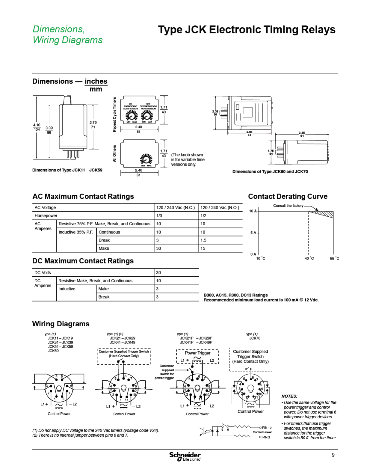
Dimensions, Wiring Diagrams .........................................9
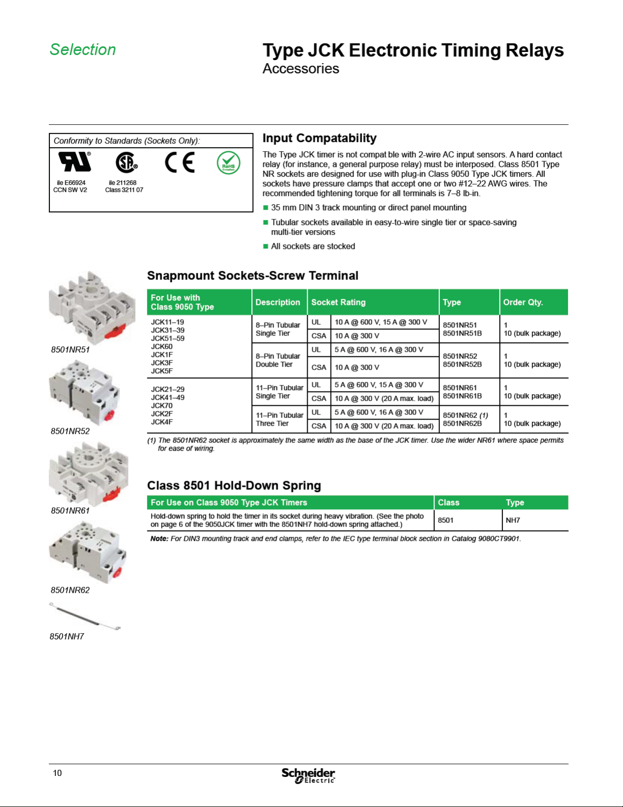
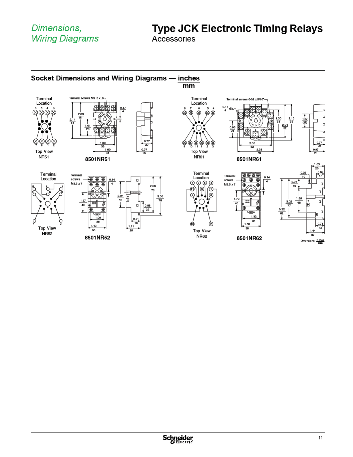
Accessories .....................................................10
3
Page 4

Application,
ON
OFF
ON
OFF
DELAY
Input
Voltage
Relay
Contacts
DELAY
ON
OFF
ON
OFF
Input
Voltage
Relay
Contacts
ON
OFF
CLOSED
OPEN
ON
OFF
Input
Voltage
T r igger
Switch
Relay
Contacts
DELAY
DELAY
DELAY
T r igger
Switch
CLOSED
OPEN
ON
OFF
Input
Voltage
ON
OFF
Relay
Contacts
DELAY
DELAY
General Information
Type JCK Electronic Timing Relays
Timing Functions
Class 9050 Type JCK1•/
JCK2• JCK3• JCK4• JCK5• JCK70
JCK60
Timing
Functions
On Delay
Off Delay
Interval
One Shot
Repeat Cycle–Off
Repeat Cycle–On
On/Off Delay
One Shot Falling
Edge
Watchdog
Trigger On Delay
Number of Pins 8 11 8 11 8 11
9050JCK Electronic Timing Functions
Function Description Timing Diagram
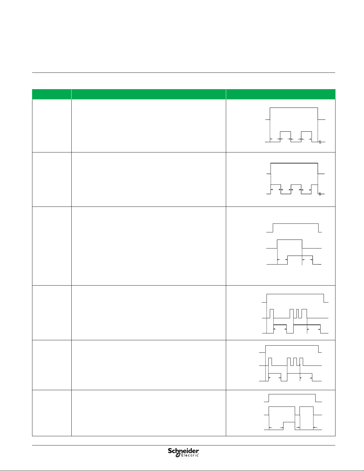
On Delay When the input voltage is applied, the time delay begins. Relay contacts change
state after time delay is complete. When the input voltage is removed, contacts
return to their shelf state. The trigger switch is not used in this function.
Interval When the input voltage is applied, the relay contacts change state immediately
and the timing cycle begins. When the time delay is complete, or when the input
voltage is removed, contacts return to shelf state. The trigger switch is not used
in this function.
Off Delay Switch
and Power Trigger
Input voltage must be applied con inuously. When the trigger switch closes,
the relay contacts change state. When the trigger switch opens, the ime delay
begins. When the delay is complete, the contacts return to their shelf state. If
the trigger switch closes before the time delay is complete, then timing is reset.
When the trigger switch opens, the delay begins again, and the relay contacts
remain in their energized state. If the input voltage is removed, the relay contacts
return to their shelf state.
One Shot Switch
and Power Trigger
Input voltage must be applied con inuously. When the trigger switch closes, he
relay contacts change state and the pre-set delay begins. During time-out, the
trigger signal is ignored. If the input voltage is removed, the relay contacts return
to their shelf state.
4
Page 5
Input
Voltage
ON
OFF
ON
OFF
Relay
Contacts
T2T1
T1
T2
ON
OFF
ON
OFF
Input
Voltage
Relay
Contacts
T1
T1 T1
T1
ON
OFF
ON
OFF
T r igger
Switch
CLOSED
OPEN
Input
Voltage
Relay
Contacts
T1
T1
DELAY
DELAY
Input
Voltage
Relay
Contacts
T r igger
Switch
ON
OFF
CLOSED
OPEN
ON
OFF
Input
Voltage
Relay
Contacts
T r igger
Switch
ON
OFF
CLOSED
OPEN
ON
OFF
DELAY
DELAY
Input
Voltage
Relay
Contacts
T r igger
Switch
ON
OFF
CLOSED
OPEN
ON
OFF
DELAY
DELAY
Application,
Type JCK Electronic Timing Relays
General Information (continued)
9050JCK Electronic Timing Functions
Function Description Timing Diagram
Repeat Cycle-Off When input voltage is applied, the time delay T1 begins. When time delay T1 is
complete, the relay contacts change state for time delay T2. This cycle repeats
until the input voltage is removed. The trigger switch is not used in this function.
Two dials are provided for independen ly adjust able repeat cycle timing ranges.
For JCK70 tim ing relay, T1 equals T2.
Repeat Cycle-On When input voltage is applied, the relay contacts change state immediately and
time delay T1 begins. When time delay T1 is complete, he contacts return to
their shelf state for time delay T1. This cycle repeats until the input voltage is
removed. The trigger switch is not used in this function.
On/Off Delay Upon application of input voltage, the time delay relay is ready to accept trigger
signals. When the trigger switch closes, a pre-set On delay begins. At the end
of the On delay, the relay contacts change state. When the trigger switch opens,
the relay contacts remain in the current state until the pre-set Off delay elapses.
At the end of the Off delay, the relay contacts return to their shelf state. The
cycle can be repeated by re-closing the trigger switch after the timing cycle ends.
If the trigger switch opens before he On delay elapses, the relay remains in its
shelf state, and the delay timer resets. If the trigger switch re-closes before the
Off delay elapses, the relay remains in its changed state, and the delay timer
resets.
One Shot Falling
Edge
Upon application of input voltage, the time delay relay is ready to accept trigger signals. When the trigger switch closes, the relay remains in its shelf state.
When the trigger switch opens, the relay contacts change state and a pre-set
time delay begins. At the end of the time delay, the relay contacts return to their
shelf state unless the trigger switch closes and opens before the time delay
elapses. Continuous cycling of the trigger signal at a rate faster than the time
delay causes the relay to remain in its changed state.
Watchdog Upon application of input voltage, the time delay relay is ready to accept trigger
signals. When the trigger switch closes, he relay contacts change state and the
pre-set time delay begins. At the end of the time delay, the relay contacts return
to their shelf state unless the trigger switch closes and opens before the ime
delay elapses. Continuous cycling of the trigger signal at a rate faster than the
delay time causes the relay to remain in its changed state
Trigger On Delay Upon application of input voltage, the time delay relay is ready to accept trigger
signals. When the trigger switch closes, a pre-set time delay begins. At the end
of the pre-set time delay, the relay contacts change state and remain in that
position as long as either the trigger signal is maintained or the input voltage
remains. If the trigger switch opens during the time delay, the relay contacts
return to their shelf state.
5
Page 6
Page 7
Page 8
Specications
Type JCK Electronic Timing Relays
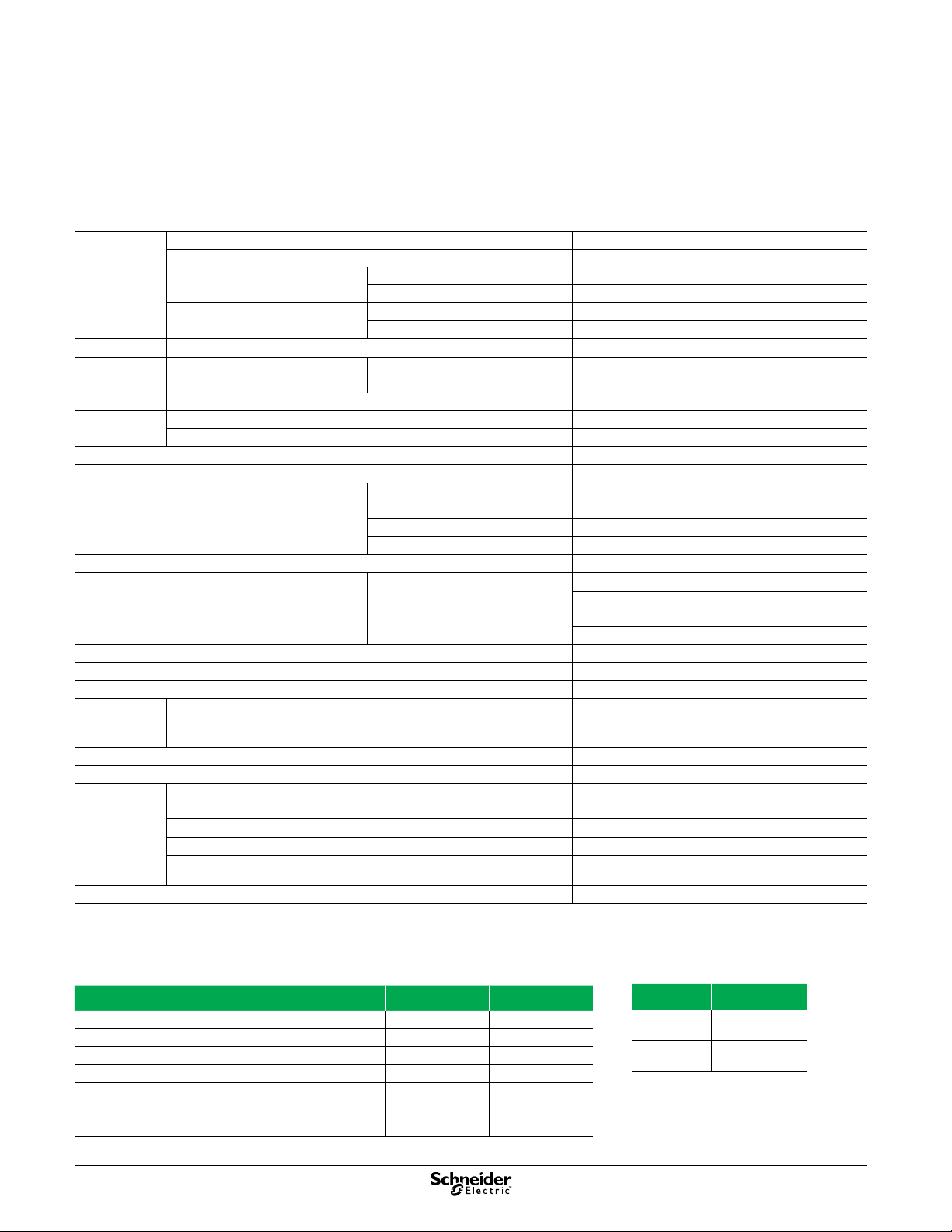
Operating Specifications
Voltage range AC operation +10%, -15% of nominal @ 50/60 Hz
DC operation +10%, -15% of nominal
Repeat
accuracy
Reset time All functions 100 ms
Temperature
range
IEC 60664-1 Degree of pollution 2
Contact material Silver nickel
Mounting position indifferent
Burden 9050JCK11–59, 1, 2–120 Vac/Vdc 2.0 VA
Relative humidity 15% to 85%, per IEC 60068-2-3
Insulation test voltage 9050JCK11–59
Transient protection 13 J, 10x 1000 ms
Vibration 10–55 Hz, 3 g max., 0 5 mm total displacement (+0.25 mm)
Shock 30 g, 11 ms duration, half sine wave
Endurance (1) Mechanical (no load, 18,000 operations/hr max.) 10 million operations
Degree of protection (IEC 60529) IP20
Max. switching frequency 1800 cycles per hour
Compliance UL Component Recognized File E78351 CCN NLDX2 (without socket)
Fuse 10 A, Class CC (e.g., Bussmann KTK-R 10)
(1) The product life expressed on this page is based on average and normal operating conditions. Actual life will vary with conditions. The above statements are not
intended to, nor shall they, create any expressed or implied warranties as to product operation or life. For more information on the listed warranty offered on this
product, refer to the Terms and Conditions of sale found in the Digest.
For constant voltage and temperature 9050JCK11–59 ±0.1%, ±0.04 s, whichever is greater
9050JCK60–70 ±0.1% of set time or ± 0.02 ms, whichever is greater
For variable voltage and temperature,
within specs
Operating (wi h the proper derating,
see curve on page 9)
Storage –67 to +185 °F (–55 to +85 °C)
Overvoltage category III
Electrical (full rated load, 1,800 operations/hr max.,
operating temperature –18 to 104 °F [–28 to 40 °C]).
UL Listed File E78351 CCN NLDX (with the proper socket from page 10)
CSA File 214768 Class 3211 07
CE EN60947-4-1, EN60947-5-1, EN61812-1
RoHS As of Series E for JCK1-59
9050JCK11–59 ±10%
9050JCK60–70 ±0.1% of set time or 0.02 s, whichever is greater
12–120 Vac/Vdc –18 to +150 °F (–28 to +65 °C)
240 Vac –18 to +122 °F (–28 to +50 °C)
9050JCK11–59, 240 Vac 3.0 VA
9050JCK60–70, 12–120 Vac/Vdc 3.0 VA
9050JCK60–70, 240 Vac 3.2 VA
9050JCK60–70
2,000 Vac
1,500 Vac between coil and contacts
1,000 Vac between open contacts
1,500 Vac between contacts of different circuitry
100,000 operations
As of Series D for JCK60 and JCK70
Electromagnetic Compatibility (EMC) Ratings
Test IEC Level
Electrostatic discharge 61000-4-2 3 (6 kV, 8 kV)
Radiated, radio-frequency, electromagnetic field 61000-4-3 3 (10 V/m)
Electrical fast transient/burst 61000-4-4 3 (2 kV, 1 kV) (1)
Surge 61000-4-5 3 (2 kV, 1 kV) (1)
Conducted disturbances, induced by radio-frequency fields 61000-4-6 3 (10 V/m)
Radiated emissions CISPR 22
Conducted emissions CISPR 22
(1) Supply port, output port, and control port
8
LED Indicators (1)
LED State
Steady (On) Power present
Flashing Device is timing
(1) The LED is not an indicator of the
output state of the timing relay.
Page 9
Page 10
Page 11
Page 12

Schneider Electric USA, Inc.
8001 Knightdale Blvd.
Kn igh tda le, NC 2 75 45
USA Customer Care Center
Tel: 888-778-2733
www.schneider-electric.us
Schneider Electric Canada
59 85 M cLau ghl in Rd.
Missassauga, Ontario, Canada L5R 1B8
Canada Customer Care Center
Tel : 80 0-565 -6 699
http://
The information and dimensions in this catalog are provided for the convenience of our customers.
While this information is believed to be accurate, Schneider Electric reserves the right to make
up dat es a nd c han ges wi tho ut p rio r no ti cat ion and as sum es n o liab ili ty f or a ny err ors or omi ssi ons .
Design: Schneider Electric
Photos: Schneider Electric
9050CT9601R04/11
Re pla ces 9050 CT9 601R03 /09 d ate d 0 6/20 09
© 2 011 Sc hne ide r Elec tric . Al l Ri ght s Rese rve d
11/ 2011
 Loading...