

Page 1
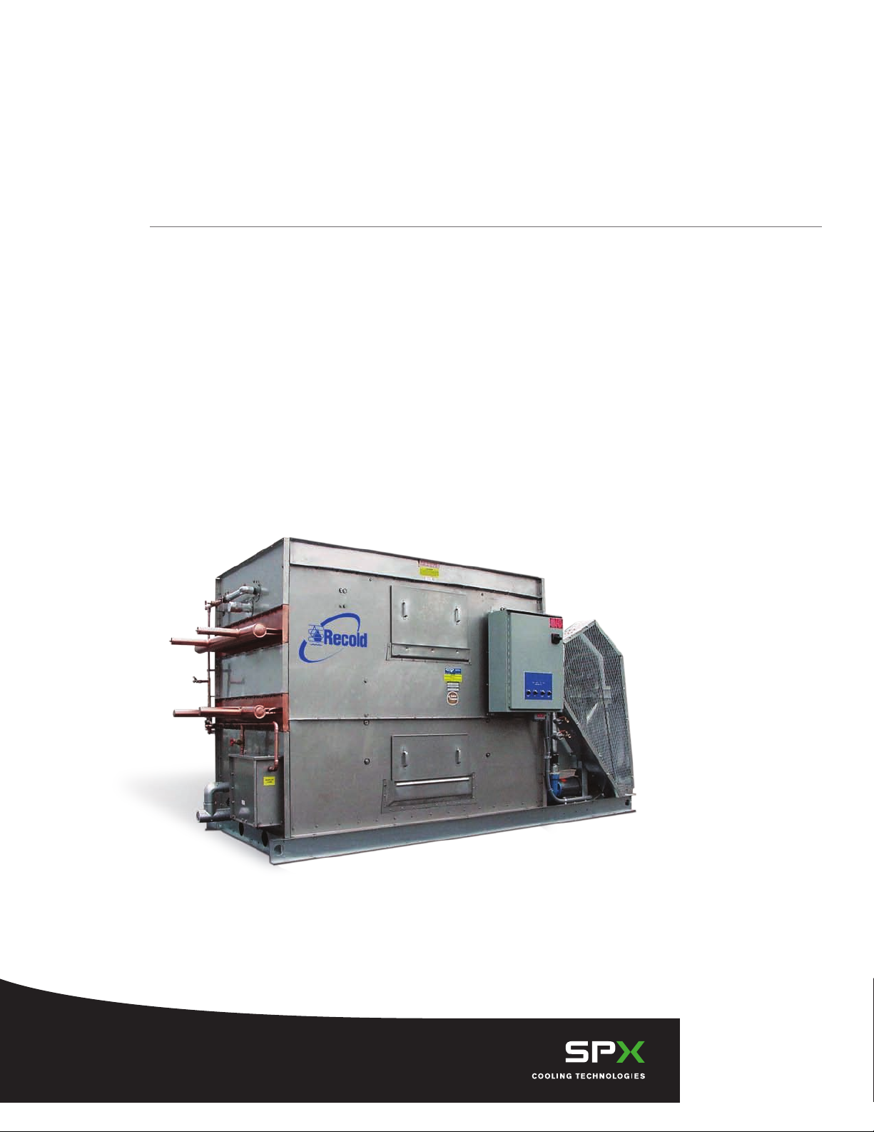
Recold® JW Series Fluid Cooler
/
/
Engineering Data
Page 2
Recold / JW Series Fluid Cooler
Nomenclature
JW L 50 B
Design Series
Optional GPM Range
L = Low Flow
H = High Flow
Approximate Coil Face
(area in sq ft)
Unit Size
Construction ............................................................................................................... 3
Schematic ................................................................................................................... 4
Engineering Data ........................................................................................................ 5
Freeze Protection ..........................................................................................................6
Selection Procedure .....................................................................................................7
Load Factors .................................................................................................................8
Rating Table ................................................................................................................10
Pressure Drop.............................................................................................................11
Accessories ................................................................................................................12
Contents
/
2
RECOLD HYDROSPRAY
Recold engineering has developed an exclusive
water distribution system called hydrospray. This
unique system provides optimum water coverage
of the heat transfer coil for maximum efficiency and
virtual elimination of harmful scale problems that
result from uneven water distribution. This process
is accomplished through a limited number of large
orifice non-clogging diffusers mounted on a heavy
duty PVC pipe water header.
IMPORTANT
Since Recold heat exchange coils are copper, the coil can be drained without regard to
internal corrosion. This must be considered with steel tubes that do not have internal
protection.
Page 3
Recold / JW Series Fluid Cooler
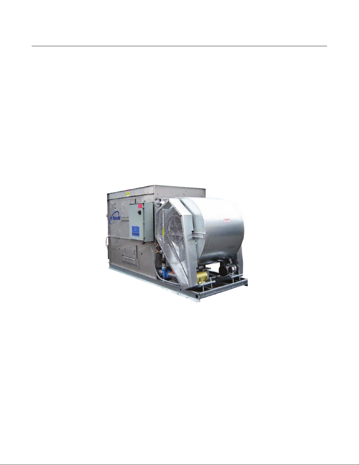
The JW Evaporative Fluid Cooler is a ruggedly built unit constructed to provide many years of durable,
dependable service with minimal maintenance requirements. Quality materials and workmanship are a key
factor in meeting this objective.
Construction
/
3
FAN MOTORS
Fan motors furnished as standard equipment are open
drip-proof type suitable for outdoor service. Motors
have a 1.15 service factor and are mounted on a
heavy duty adjustable base located for easy access.
FAN GUARD SCREENS
All moving parts are protected with OSHA approved
galvanized steel screens. Each guard is easily
removed for access to the fan.
FAN SECTION
The centrifugal fan is
forward curved, statically
and dynamically balanced
and constructed of
galvanized steel. The fan
housing has curved inlet
rings for efficient air entry
and discharge into the
pan. Fans are mounted
on a solid steel shaft
coated to resist corrosion.
Heavy duty, pillow block
type, self-aligning ball
bearings are located at
each end of the fan shaft.
No intermediate bearings are
required
Extended lube lines are supplied as standard
equipment to allow servicing bearings without
removal of fan guard screens.
WATER CIRCULATION PUMP
The water circulation pump is a close coupled, bronze
fitted centrifugal type with mechanical seal. Each
pump is factory mounted and piped. Standard motor
is open drip-proof suitable for outdoor service.
DRIFT ELIMINATORS
Eliminators are constructed of PVC assemblies in
removable, easy to handle sections. Each section has
a three break design allowing three changes in air
flow and measure approximately 5 inches in depth.
The use of durable PVC eliminates the corrosion
problems associated with galvanized eliminators.
HEAT EXCHANGE COIL
Coil tube bundle is constructed of 5⁄8" copper
tubing with stainless steel tube sheets
and copper headers. The copper
construction offers a
noncorrosive coil for extended
service life.
ACCESS DOORS
Large rectangular access
doors are strategically
located to provide access
to both upper water
distribution system and
lower pan basin. The
patented doors provide a
complete air and water tight
seal without the use of
gaskets or fasteners
WATER MAKE-UP
Water make-up is provided
by a solid brass float valve with arm
and float ball installed in an external float
b o x . This allows easy observation of the water
operating level and maintenance of the valve with unit
in operation.
Construction: The Evaporative Fluid Cooler sump pan is constructed of 300 stainless steel and casing panels
are constructed of heavy gauge, G-235 galvanized steel. The sump pan and casing panels are flanged outward
so that all the connecting fasteners are located outside the flooded section of the unit to help prevent leaks
in the unit and provides a more permanent watertight joint. To provide further protection from corrosion, no
welded joints are located below the water line. The unit is designed for a 30 psf on any projected area and ships
in one piece on a minimum 6" high stainless steel channel base to help in handling and installation of the unit.
Page 4
Recold / JW Series Fluid Cooler
A
B
G
F
C
L L
K
H
D
J
12" 2"
DRAIN AND
OVERFLOW
P
EXTERNAL
FLOAT BOX
INLET
CONNECTION
SPRAY HEADER
CLEANOUT
OUTLET
CONNECTION
12"
WATER SUPPLY Q
INLET
OUTLET
ELIMINATOR
ACCESS
ACCESS
DOOR
2" LIFTING
HOLE (4)
7
/8" MOUNTING
HOLE (6)
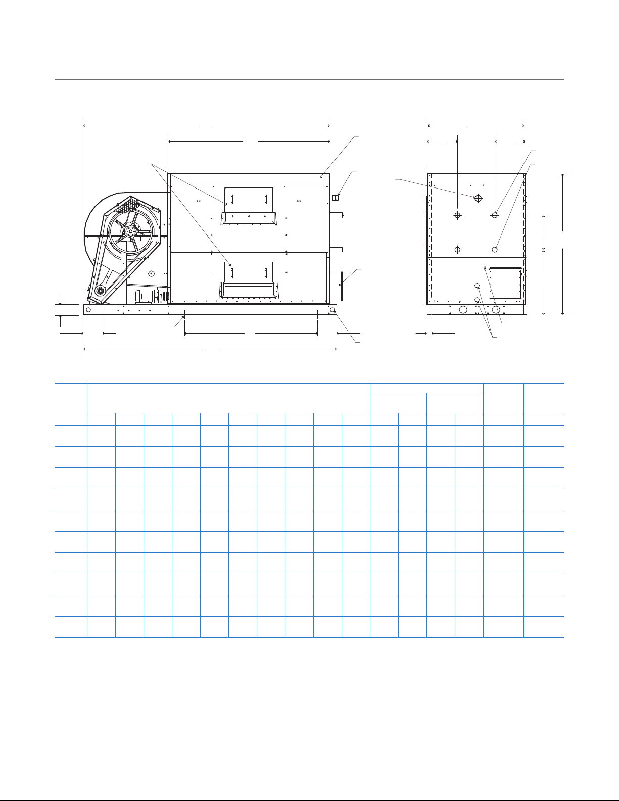
Schematic
/
4
Access Doors Overflow
Model
A B C D F G H J K L Top Bottom Top Bottom P Q
JW10 80" 76" 31" 84" 32
JW15 96" 76" 37" 102" 311⁄2" 191⁄2" — 6" 65" 16 1 1 — — 21⁄2"
JW25 1153⁄4" 77" 451⁄4" 124" 34" 191⁄2" 511⁄4" 6 763⁄4" 201⁄2" 1 1 1
JW35 1391⁄2" 801⁄4" 551⁄2" 144" 38" 191⁄2" 51" 6" 92" 141⁄2" 1 1 1
JW50 1721⁄4" 921⁄2" 667⁄8" 1801⁄4" 41" 191⁄2" 713⁄4" 6" 115" 173⁄8" 2 1 2
JW70 1841⁄4" 981⁄2" 931⁄4" 192" 47" 191⁄2" 841⁄2" 8" 115"
JW85 208" 981⁄2" 933⁄8" 217" 47" 191⁄2" 961⁄2" 8" 1391⁄4"
JW100 221" 1181⁄2" 1001⁄2" 225" 67" 191⁄2" 80" 10" 1391⁄2"
JW115 2451⁄2" 1181⁄2" 1001⁄2" 249" 67" 191⁄2" 104" 10" 1641⁄2"
JW130 269" 1181⁄2" 1001⁄2" 273" 67" 191⁄2" 128" 10" 188"
Note
1 Use this bulletin for preliminary layouts only. Obtain current
drawing from your Recold sales representative.
2 If required add 6" for positive closure dampers. If required
add 6" for booster coil section.
Dimensions
1
⁄2" 191⁄2" — 6" 53" 131⁄2" 1 1 — — 21⁄2"
note 4
note 4
note 4
note 4
note 4
3 An additional bottom access door is installed on the
connection end.
4. Consult Recold for coil connection locations.
5 If supporting the unit on beams, refer to the Recold
suggested supporting steel drawing for required mounting
Far Side Near Side
2 1 2
2 1 2
2 2 2
2 2 2
2 2 2
1
note 3
1
note 3
1
note 3
1
note 3
1
note 3
2
note 3
2
note 3
2
note 3
Drain
FPT
21⁄2"
21⁄2"
21⁄2" 1"
3" 11⁄4"
3" 11⁄4"
4" 11⁄4"
4" 11⁄4"
4" 11⁄4"
Water
Supply
FPT
1
⁄2"
1
⁄2"
1
⁄2"
3
⁄4"
hole location.
Page 5

Recold / JW Series Fluid Cooler
Engineering Data
/
5
Model
Fan Motor
hp*
Air Volume
cfm
Fan
RPM
Standard Fan
Motor Frame
JW10A 2 5280 689 145T
JW10B 2 5150 706 145T
JW10C 3 5450 825 182T
JW15B 5 8500 729 184T
JW15C 5 8300 740 184T
JW25A 5 11700 500 184T
JW25B 5 11800 523 184T
JW25C 7
JW35A 7
1
⁄2 13000 614 213T
1
⁄2 19000 413 213T 1 110 4.0 2955 4300
Pump Motor hpSpray Water
GPM
1
⁄2 40 2.0 910 1400
1
⁄2 40 2.0 955 1400
1
⁄2 40 2.0 1005 1500
1
⁄2 50 2.0 1365 2000
1
⁄2 50 2.0 1435 2400
3
⁄4 70 4.0 1850 2800
3
⁄4 70 4.0 1955 2900
3
⁄4 70 4.0 2075 3200
Sump Heater
kW
Approximate Weight lb
shipping operating
JW35B 10 20000 462 215T 1 110 4.0 3140 4600
JW35C 10 19500 476 215T 1 110 4.0 3305 5000
JW50A 15 30200 385 254T 2 150 6.0 4380 6700
JW50B 15 29200 397 254T 2 150 6.0 4635 7200
JW50C 15 28400 385 254T 2 150 6.0 4885 7600
JW70B 20 37200 385 256T 3 250 8.0 6685 10200
JW70C 25 39000 415 284T 3 250 8.0 7085 10900
JW85B 30 52300 415 286T 3 325 11.0 7725 11900
JW85C 30 50000 430 286T 3 325 11.0 8185 12900
JW100B 30 58300 270 286T 5 375 11.0 9170 16870
JW100C 30 61000 280 286T 5 365 11.0 9675 17775
JW115B 40 66000 280 324T 5 400 14.0 10080 19050
JW115C 40 69000 290 324T 5 400 14.0 10670 20170
JW130B 50 76500 300 326T 5 450 16.0 11025 21425
JW130C 50 80000 305 326T 5 450 16.0 11720 22620
* For static pressure from 1⁄4 to 1⁄2 ESP use next size larger motor
Model
JWL
Circuits Connection OD Circuits Connection OD Circuits Connection OD
JW10A 10 2
JW10B 21 2
JW10C 21 2
JW15B 26 2
JW15C 26 2
JW25A 33 2
JW25B 33 2
JW25C 33 2
JW35A 41 2
JW35B 41 2
JW35C 41 2
JW50A 50 2
JW50B 50 2
JW50C 50 2
JW70B 70 4
JW70C 70 4
JW85B 70 4
JW85C 70 4
JW100B 76 4
JW100C 76 4
JW115B 76 4
JW115C 76 4
JW130B 76 4
JW130C 76 4
@
2 5⁄8" 43 21 2 @ 2 5⁄8" 16 — — 9.7
@
2 5⁄8" 43 42 2 @ 2 5⁄8" 20 — — 9.7
@
2 5⁄8" 43 42 2 @ 2 5⁄8" 24 — — 9.7
@
3 1⁄8" 64 52 2 @ 3 1⁄8" 31 — — 14.5
@
3 1⁄8" 64 52 2 @ 3 1⁄8" 37 — — 14.5
@
3 1⁄8" 95 66 2 @ 3 1⁄8" 37 — — 21.6
@
3 1⁄8" 95 66 2 @ 3 1⁄8" 47 — — 21.6
@
3 1⁄8" 95 66 2 @ 3 1⁄8" 57 — — 21.6
@
3 1⁄8" 163 82 2 @ 3 1⁄8" 54 — — 32.5
@
3 1⁄8" 163 82 2 @ 3 1⁄8" 70 164 4 @ 3 1⁄8" 32.5
@
3 1⁄8" 163 82 2 @ 3 1⁄8" 86 205 4 @ 3 1⁄8" 32.5
@
3 1⁄8" 248 100 2 @ 3 1⁄8" 82 — — 49.6
@
3 1⁄8" 248 100 2 @ 3 1⁄8" 106 200 4 @ 3 1⁄8" 49.6
@
3 1⁄8" 248 100 2 @ 3 1⁄8" 130 250 4 @ 3 1⁄8" 49.6
@
3 1⁄8" 374 140 4 @ 3 1⁄8" 146 280 8 @ 3 1⁄8" 70.4
@
3 1⁄8" 374 140 4 @ 3 1⁄8" 182 350 8 @ 3 1⁄8" 70.4
@
3 1⁄8" 454 140 4 @ 3 1⁄8" 177 280 8 @ 3 1⁄8" 85.5
@
3 1⁄8" 454 140 4 @ 3 1⁄8" 200 350 8 @ 3 1⁄8" 85.5
@
3 1⁄8" 748 152 4 @ 3 1⁄8" 212 304 8 @ 3 1⁄8" 92.5
@
3 1⁄8" 748 152 4 @ 3 1⁄8" 262 380 8 @ 3 1⁄8" 92.5
@
3 1⁄8" 880 152 4 @ 3 1⁄8" 247 304 8 @ 3 1⁄8" 108.9
@
3 1⁄8" 880 152 4 @ 3 1⁄8" 305 380 8 @ 3 1⁄8" 108.9
@
3 1⁄8" 1012 152 4 @ 3 1⁄8" 305 304 8 @ 3 1⁄8" 125.2
@
3
Sump Capacity
gal
1
⁄8" 1012 152 4
Note
Inlet and outlet connection sizes shown are standard
copper OD and are sized for nominal flow rates. Actual
sizes should be specified to conform to job requirements.
JW
Coil Volume
JWH
Coil Face Area
gal
1
@
⁄8" 349 380 8
3
1
@
⁄8" 125.2
3
If special connections are required, such as flanges or
threaded fittings, consult your Recold sales representative.
Connection quantity is total of in and out connections
sq ft
Page 6

Recold / JW Series Fluid Cooler
Freeze Protection
/
6
For the most part, evaporative closed circuit coolers
will be installed for operation on a year-round basis.
Units installed in a cold climate must be provided with
adequate freeze protection for both the recirculating
water and the heat exchange coil for proper
equipment operation and maintenance.
RECIRCULATING WATER
The operation of evaporative cooled equipment under
approximately full load conditions will prevent freezing
of the recirculated water. However, during periods of
very little or no heat load when fans and pumps are
shut down, some form of freeze protection must be
used.
A simple form of freeze protection commonly used
is a remote sump tank inside a heated building
below the evaporative cooled equipment. The water
circulation pump is located at the remote tank
circulating water through the evaporative cooler
during load conditions. When the unit is shut down,
the water drains down into the remote sump tank
which is in a heated atmosphere.
The remote sump installation may be unacceptable in
some cases due to unit location or space limitations.
For these applications, pan water freeze protection
may be attained by means of an optional electric
heater located inside the unit pan. Electric pan
heaters are designed to prevent pan water freezing
during unit shut down with fans and pumps idle.
Water lines to and from the unit, pump, pump
discharge and drain lines must be wrapped with a
heat-tracing element and insulated to protect them
from freezing.
Table 1 Glycol Flow Correction Factors
Unit Model
JW/JWL
10A thru 35C
50A thru 50C
70B thru 130C
Ethylene
Glycol
By Volume
40 50 70 90 100 125 150 175 Above
20% 1.07 1.05 1.02 1.00 1.00 1.00 1.00 1.00 1.00
30% 1.10 1.07 1.02 1.01 1.00 1.00 1.00 1.00 1.00
40% 1.14 1.11 1.05 1.01 1.00 1.00 1.00 1.00 1.00
50% 1.16 1.13 1.06 1.01 1.00 1.00 1.00 1.00 1.00
20% 1.12 1.09 1.05 1.03 1.02 1.00 1.00 1.00 1.00
30% 1.16 1.12 1.07 1.04 1.02 1.00 1.00 1.00 1.00
40% 1.19 1.16 1.11 1.06 1.04 1.01 1.00 1.00 1.00
50% 1.23 1.21 1.14 1.08 1.05 1.01 1.00 1.00 1.00
20% 1.15 1.11 1.09 1.06 1.04 1.03 1.01 1.00 1.00
30% — 1.18 1.11 1.07 1.05 1.03 1.01 1.00 1.00
40% — 1.20 1.15 1.10 1.07 1.05 1.03 1.00 1.00
50% — 1.23 1.20 1.11 1.11 1.07 1.04 1.00 1.00
Design Flow GPM
HEAT EXCHANGE COIL PROTECTION
The best means of heat exchanger coil freeze
protection is to circulate an ethylene glycol water
solution. The solution freeze points with respective
ethylene glycol by volume are given in Table 11
below. This method will allow freeze protection
irrespective of heat load or unit shut down.
Some applications will not permit the use of an
ethylene glycol solution. Under these circumstances,
other means of freeze protections must be used and
the following rules strictly adhered to.
1. Maintain full flow through the coil
2. Maintain heat load on the coil at all time so that the
leaving water temperature does not drop below
+50°F
Full flow alone will not protect the coil.
Temperature of +50°F must also be maintained.
Methods of maintaining the recommended fluid
temperature may vary with system design and
operation. A simple means of preventing heat loss
may be to locate the unit indoors allowing a heated
atmosphere. Adequate space and ductwork must be
provided for proper operation.
Units operating in low ambient conditions with a
heat load which becomes very low or drops off
completely may require the addition of an artificial
load to maintain safe fluid temperature. The amount
of artificial load required may be reduced by means
of discharge positive closure dampers. The addition
of the dampers will prevent induced air circulation or
the chimney effect which may occur during unit shut
down.
The above methods of coil freeze protection, when
properly applied and maintained will provide good
equipment protection. All methods, other than
those using an adequate antifreeze solution, should
provide a means of emergency coil draining. It is
recommended that automatic drain valves and air
vents with vacuum breakers be installed on each
coil circuit. Adequately size drains with heat-tracing
tape and insulation should be provided for free
drainage. Should the circulating pump fail or the water
temperature leaving the coil drop below 50°F for any
reason, the coil will automatically drain preventing
freeze damage.
Ethylene Glycol (by volume)
Freeze
Point °F
20% 30% 40% 50%
14 3 -14 -38
Page 7

Recold / JW Series Fluid Cooler
Selection Procedure
/
Closed circuit cooler selections can easily be made by using the information on pages 6 through 11. The
examples below demonstrate proper procedures for water and ethylene glycol solutions. Other fluids can be
cooled, but since their heat transfer and flow characteristics may vary, please contact your local Recold sales
representative for assistance.
7
WATER SELECTION EXAMPLE
Select a unit to cool 225 GPM of water from 102°F to
90°F at 76°F wet bulb temperature.
1. Determine Range:
102°F - 90°F = 12°F Range
2. Determine Approach:
90°F - 76°F = 14°F Approach
3. Select Load Factor — Enter Unit Load Factor Table 2
for 76°F wet bulb. Select load factor based on
12°F range and 14°F approach. Load factor in this
example equals 3.3. When wet bulb temperature
is an odd number interpolate between appropriate
tables to determine the load factor.
4. Select Unit Model — Table 3, the load factor
determined in step 3 falls between 3.0 and 3.5.
Enter the 3.0 column and read down to the smallest
unit flow rating which is greater than or equal to
225 GPM. For the Model JWL35B, interpolate
between 245 and 190 GPM to determine the
flow rating at the 3.3 load factor. Interpolation
gives a rating of 212 GPM which is less than the
design requirement. Select a Model JWL35C and
again interpolate between load factor columns
to determine flow rating. The second selection
provides a flow rating of 245 GPM which exceeds
the design requirement. The correct unit size is,
therefore, a Model 35C
5. Determine Flow Limitations — Enter Table 3 at unit
size determined in Step 4 to select a JWL low flow
or JW standard flow unit. The Model 35C with 225
GPM design flow falls within the standard coil flow
limitations. The correct unit selection is, therefore,
a JW35C.
6. Determine Coil Pressure Drop — Enter the Coil
Pressure Drop Table at 225 GPM and read across
to the unit model column to select pressure drop
reading. In this example, pressure drop equals
4.8 PSI.
ETHYLENE GLYCOL EXAMPLE
Select a unit to cool 75 GPM of 40% by volume
ethylene glycol from 107°F to 85°F with 78°F wet
bulb.
1. Determine Range:
107°F - 85°F = 22°F Range
2. Determine Approach:
85°F - 78°F = 7°F Approach
3. Select Load Factor — Enter Table 2 for 78°F wet bulb
and select load factor at design range and approach.
Select 6.0 factor.
4. Select Test Unit Model — Enter the Unit Rating
Table 3 at the 6.0 load factor and read down to the
smallest unit flow rating greater than or equal to the
design 75 GPM. Select the test model JWL35C
5. Correct Flow for Ethylene Glycol — The flow correction
factor obtained from Table 1 is 1.04. 75 GPM x 1.04
= 78 GPM
6. Adjust Model Selection — Re-enter Table 3 at the 6.0
load factor and make selection based on corrected
flow of 78 GPM. The adjusted unit selection is the
Model JWL50A indicating an 80 GPM rating
7. Determine Flow Limitations — Enter Table 3 at unit
size determined in Step 6 to select a JWL low flow
or JW standard flow unit. The Model 50A with
75 GPM design flow falls within the low flow coil
limitations. The correct unit selection is, therefore,
a JWL50A.
8. Determine Coil Pressure Drop — For ethylene glycol
pressure drop calculation, the conversion factor
from Table 5 must be applied to design flow before
entering Table 4. 75 GPM x 1.05 = 79 GPM.
The coil pressure drop for 79 GPM is 2.4 PSI
DEFINITIONS
Range: the difference between the entering and
leaving water temperatures (WT in – WT out).
Approach: the difference between the leaving water
temperature and the web bulb temperature (WT out
– WB).
Load BTUH =
GPM x 500 x Sp. Gr. x Sp. Ht. x (T
1
– T2) where
Sp. Gr. = specific gravity at average temperature
Sp. Ht. = specific heat at average temperature
T1 = entering temperature
T2 = leaving temperature
Page 8

Recold / JW Series Fluid Cooler
TABLE NO. 2
60° WET BULB
6 8 10 12 14 16 18 20 22 24 26 28 30 32 34 36 38 40
7
8
9
10
11
12
2.9 3.5 4.0 4.5 4.8 5.1 5.4 5.6 5.8 6.0 6.2 6.4 6.5 6.6 6.8 6.9 7. 0 7. 2
13
2.8 3.2 3.8 4.2 4.5 4.9 5.1 5.4 5.6 5.8 5.9 6.2 6.3 6.4 6.5 6.7 6.8 6.9
14
2.5 3.1 3.6 4.0 4.3 4.6 4.9 5.1 5.3 5.5 5.7 5.9 6.0 6.2 6.3 6.4 6.6 6.8
15
2.4 3.0 3.5 3.9 4.1 4.5 4.7 4.9 5.2 5.4 5.5 5.7 5.8 6.0 6.1 6.3 6.4 6.6
16
2.3 2.8 3.3 3.7 4.0 4.3 4.6 4.8 4.9 5.1 5.3 5.5 5.6 5.7 5.9 6.1 6.3 6.4
17
2.2 2.7 3.2 3.6 3.9 4.1 4.4 4.6 4.8 4.9 5.1 5.3 5.4 5.7 5.8 5.9 6.0 6.2
18
2.1 2.6 3.0 3.6 3.8 4.0 4.2 4.4 4.6 4.8 4.9 5.1 5.3 5.4 5.6 5.8 5.9 6.0
19
2.0 2.5 2.9 3.3 3.6 3.9 4.1 4.3 4.5 4.7 4.8 4.9 5.2 5.3 5.4 5.6 5.8 5.9
20
1. 9 2.4 2.8 3.2 3.4 3.7 3.9 4.2 4.3 4.5 4.7 4.8 4.9 5.1 5.3 5.4 5.6 5.7
APPROACH
21
1. 9 2.4 2.7 3.1 3.4 3.6 3.9 4.1 4.2 4.4 4.6 4.7 4.9 5.0 5.3 5.3 5.4 5.6
22
1. 8 2.3 2.6 3.0 3.2 3.5 3.7 3.9 4.1 4.3 4.4 4.6 4.7 4.9 5.0 5.2 5.3 5.4
23
1. 8 2.3 2.6 3.0 3.2 3.5 3.7 3.9 4.1 4.3 4.4 4.6 4.7 4.8 5.0 5.2 5.3 5.4
24
1. 7 2.1 2.5 2.8 3.1 3.3 3.5 3.7 3.9 4.1 4.3 4.4 4.5 4.6 4.8 4.9 5.1 5.2
25
1. 6 2.1 2.4 2.7 3.0 3.2 3.4 3.6 3.8 3.9 4.1 4.2 4.4 4.6 4.7 4.8 4.9 5.1
26
1. 6 2.0 2.3 2.6 2.9 3.2 3.3 3.5 3.7 3.9 4.0 4.1 4.3 4.4 4.6 4.7 4.8 4.9
27
1. 5 2.0 2.3 2.6 2.8 3.1 3.3 3.4 3.6 3.8 3.9 4.1 4.2 4.3 4.4
28
5 1. 9 2.2 2.5 2.8 3.0 3.2 3.4 3.5 3.7 3.8 4.0 4.1 4.2 4.3 4.4 4.6 4.7
1.
29
1. 4 1. 8 2.1 2.4 2.7 2.9 3.1 3.3 3.4 3.6 3.7 3.9 4.0 4.1 4.2 4.4 4.5 4.6
30
1. 4 1. 8 2.1 2.4 2.6 2.8 3.0 3.2 3.3 3.5 3.6 3.8 3.9 4.0 4.1 4.3 4.4 4.5
6.0 6.4 6.7 7. 2 7. 3 7. 5 7. 7 7. 9 8.0 8.2
5.6 6.0 6.4 6.7 6.9 7. 1 7. 3 7. 5 7. 6 7. 8 7. 9 8.0
4.3 4.8 5.3 5.7 6.0 6.3 6.5 6.8 6.9 7. 1 7. 3 7. 4 7. 6 7. 7 7. 8 7. 9 8.0
4.0 4.5 5.0 5.4 5.7 6.0 6.2 6.4 6.6 6.8 6.9 7. 1 7. 3 7. 4 7. 5 7. 6 7. 8
3.8 4.3 4.7 5.0 5.3 5.6 5.9 6.1 6.3 6.5 6.6 6.8 6.9 7. 0 7. 2 7. 3 7. 4
RANGE
Load Factors
/
4.6 4.7 4.8
62° WET BULB
6 8 10 12 14 16 18 20 22 24 26 28 30 32 34 36 38 40
7
8
9
10
11
3.0 3.6 4.2 4.6 4.9 5.2 5.5 5.7 6.0 6.2 6.3 6.5 6.7 6.8 7. 0 7. 1 7. 2 7. 3
12
2.8 3.5 4.0 4.4 4.7 5.0 5.3 5.5 5.7 5.9 6.1 6.3 6.4 6.5 6.7 6.8 7. 0 7. 1
13
2.7 3.3 3.7 4.1 4.5 4.8 5.1 5.3 5.5 5.7 5.9 6.0 6.2 6.3 6.5 6.6 6.8 6.9
14
2.5 3.1 3.5 3.9 4.3 4.6 4.8 5.0 5.2 5.5 5.6 5.8 5.9 6.1 6.2 6.3 6.5 6.7
15
2.2 2.9 3.3 3.7 4.1 4.3 4.6 4.8 5.0 5.2 5.4 5.5 5.7 5.8 6.0 6.1 6.3 6.4
16
2.2 2.8 3.0 3.6 3.9 4.2 4.4 4.6 4.8 5.1 5.2 5.4 5.5 5.7 5.8 6.0 6.1 6.3
17
2.1 2.7 3.1 3.5 3.8 4.1 4.3 4.5 4.7 4.9 5.0 5.2 5.4 5.5 5.7 5.8 6.0 6.1
18
2.1 2.5 3.0 3.4 3.7 3.9 4.2 4.4 4.5 4.7 4.9 5.0 5.2 5.3 5.5 5.6 5.8 5.9
19
2.0 2.4 2.9 3.2 3.5 3.8 4.0 4.2 4.4 4.6 4.7 4.9 5.0 5.2 5.3 5.4 5.6 5.8
20
1. 9 2.3 2.8 3.1 3.4 3.6 3.9 4.1 4.2 4.4 4.6 4.7 4.9 5.0 5.2 5.3 5.5 5.6
APPROACH
21
1. 8 2.3 2.7 3.0 3.3 3.5 3.8 4.0 4.1 4.3 4.5 4.6 4.8 4.9 5.1 5.2 5.3 5.5
22
1. 8 2.2 2.6 2.9 3.2 3.4 3.7 3.9 4.0 4.2 4.4 4.5 4.7 4.8 4.9 5.1 5.2 5.4
23
1. 7 2.1 2.5 2.8 3.1 3.3 3.5 3.7 3.9 4.1 4.3 4.4 4.5 4.7 4.8 4.9 5.1 5.2
24
1. 6 2.1 2.5 2.7 3.0 3.2 3.4 3.6 3.8 4.0 4.1 4.3 4.4 4.6 4.7 4.8 5.0 5.1
25
1. 6 2.0 2.4 2.6 2.9 3.1 3.3 3.5 3.7 3.9 4.0 4.2 4.3 4.5 4.6 4.7 4.8 5.0
26
1. 5 2.0 2.3 2.6 2.8 3.1 3.3 3.4 3.6 3.8 3.9 4.1 4.2 4.4 4.5 4.6 4.7 4.9
27
1. 5 1. 9 2.2 2.5 2.8 3.0 3.2 3.4 3.6 3.7
28
5 1. 8 2.2 2.4 2.7 2.9 3.1 3.3 3.5 3.6 3.7 3.9 4.0 4.2 4.3 4.4 4.5 4.6
1.
29
1. 4 1. 8 2.1 2.3 2.6 2.8 3.0 3.2 3.4 3.5 3.6 3.8 3.9 4.1 4.2 4.3 4.4 4.5
30
1. 4 1. 7 2.0 2.3 2.5 2.8 3.0 3.1 3.3 3.4 3.5 3.7 3.8 4.0 4.1 4.2 4.3 4.4
5.8 6.3 6.6 6.9 7. 1 7. 3 7. 5 7. 7 7. 9 7. 9 8.1
4.9 5.4 5.8 6.2 6.5 6.7 6.9 7. 1 7. 3 7. 4 7. 6 7. 8 7. 9 8.0 8.1
4.1 4.6 5.0 5.4 5.8 6.0 6.4 6.5 6.7 6.9 7. 0 7. 2 7. 3 7. 5 7. 6 7. 8 7. 9
3.8 4.3 4.8 5.1 5.5 5.8 6.0 6.2 6.4 6.6 6.8 6.9 7. 0 7. 2 7. 3 7. 4 7. 6
RANGE
3.8 4.0 4.1 4.3 4.4 4.5 4.6 4.7
8
64° WET BULB
6 8 10 12 14 16 18 20 22 24 26 28 30 32 34 36 38 40
7
8
9
10
11
2.9 3.5 4.1 4.5 4.9 5.1 5.4 5.6 5.8 6.0 6.2 6.3 6.5 6.7 6.8 6.9 7. 0 7. 2
12
2.7 3.4 3.9 4.3 4.6 4.9 5.1 5.4 5.6 5.8 6.0 6.1 6.3 6.4 6.6 6.7 6.8 7. 0
13
2.6 3.2 3.6 4.0 4.4 4.6 4.9 5.2 5.4 5.5 5.7 5.9 6.0 6.2 6.3 6.5 6.6 6.8
14
2.4 3.0 3.4 3.8 4.2 4.4 4.7 4.9 5.1 5.3 5.5 5.7 5.8 5.9 6.1 6.2 6.4 6.6
15
2.2 2.8 3.2 3.6 4.0 4.2 4.5 4.7 4.9 5.0 5.2 5.4 5.6 5.7 5.9 6.0 6.1 6.3
16
2.1 2.7 3.1 3.5 3.8 4.1 4.3 4.5 4.7 4.9 5.1 5.3 5.4 5.5 5.7 5.9 6.0 6.1
17
2.1 2.6 3.0 3.4 3.7 4.0 4.2 4.4 4.6 4.7 4.9 5.1 5.3 5.4 5.6 5.7 5.8 6.0
18
2.0 2.5 2.9 3.3 3.6 3.8 4.1 4.3 4.4 4.6 4.8 4.9 5.1 5.2 5.4 5.5 5.7 5.8
19
1. 9 2.4 2.8 3.1 3.4 3.7 3.9 4.1 4.3 4.5 4.6 4.8 4.9 5.1 5.2 5.3 5.5 5.7
20
1. 8 2.3 2.7 3.0 3.3 3.5 3.8 4.0 4.1 4.3 4.5 4.6 4.8 4.9 5.1 5.2 5.4 5.5
APPROACH
21
1. 8 2.2 2.6 2.9 3.2 3.4 3.7 3.9 4.0 4.2 4.4 4.5 4.7 4.8 5.0 5.1 5.2 5.4
22
1. 8 2.1 2.5 2.8 3.1 3.3 3.6 3.8 3.9 4.1 4.3 4.4 4.6 4.7 4.8 5.0 5.1 5.3
23
1. 7 2.1 2.4 2.7 3.0 3.3 3.4 3.6 3.8 4.0 4.1 4.3 4.4 4.6 4.7 4.8 5.0 5.1
24
1. 6 2.0 2.4 2.7 2.9 3.2 3.3 3.5 3.7 3.9 4.0 4.2 4.3 4.5 4.6 4.7 4.9 5.0
25
1. 6 1. 9 2.3 2.6 2.8 3.1 3.2 3.4 3.6 3.8 3.9 4.1 4.2 4.4 4.5 4.6 4.7 4.9
26
1. 5 1. 9 2.2 2.5 2.7 3.0 3.2 3.3 3.5 3.7 3.8 4.0 4.1 4.3 4.4 4.5 4.6 4.8
27
1. 5 1. 8 2.1 2.4 2.7 2.9 3.1 3.3 3.5
28
4 1. 8 2.1 2.3 2.6 2.8 3.0 3.2 3.4 3.5 3.6 3.8 3.9 4.1 4.2 4.3 4.4 4.5
1.
29
1. 4 1. 7 2.0 2.3 2.5 2.8 2.9 3.1 3.3 3.4 3.5 3.7 3.8 4.0 4.1 4.2 4.3 4.4
30
1. 3 1. 6 1. 9 2.2 2.4 2.7 2.9 3.0 3.2 3.3 3.4 3.6 3.7 3.9 4.0 4.1 4.2 4.3
5.6 6.1 6.4 6.7 7. 0 7. 1 7. 4 7. 5 7. 7 7. 8 8.0
4.8 5.3 5.6 6.0 6.3 6.6 6.8 7. 0 7. 1 7. 3 7. 5 7. 6 7. 7 7. 8 7. 9 8.0
3.9 4.5 4.9 5.3 5.6 5.9 6.2 6.4 6.6 6.7 6.9 7. 1 7. 2 7. 3 7. 5 7. 6 7. 7
3.7 4.3 4.7 5.0 5.3 5.6 5.9 6.1 6.3 6.5 6.6 6.8 6.9 7. 0 7. 1 7. 3 7. 5
RANGE
3.6 3.7 3.9 4.0 4.2 4.3 4.4 4.5 4.6
68° WET BULB
6 8 10 12 14 16 18 20 22 24 26 28 30 32 34 36 38 40
7
4.4 4.9 5.1 5.7 6.1 6.4 6.6 6.9 7. 0 7. 2 7. 4 7. 5 7. 6 7. 8 7. 9
8
4.0 4.6 5.0 5.4 5.7 6.0 6.2 6.5 6.6 6.8 7. 0 7. 1 7. 2 7. 4 7. 5 7. 6 7. 7
9
3.7 4.3 4.7 5.1 5.4 5.6 5.9 6.1 6.3 6.5 6.6 6.8 6.9 7. 1 7. 2 7. 3 7. 5
10
2.9 3.5 4.0 4.4 4.8 5.1 5.3 5.6 5.7 6.0 6.1 6.3 6.5 6.6 6.7 6.8 7. 0 7. 1
11
2.7 3.3 3.8 4.2 4.6 4.9 5.1 5.4 5.5 5.7 5.9 6.1 6.2 6.4 6.5 6.7 6.8 6.9
12
2.6 3.1 3.6 4.0 4.4 4.7 4.9 5.1 5.3 5.5 5.7 5.8 6.0 6.1 6.3 6.4 6.6 6.7
13
2.4 3.0 3.4 3.8 4.2 4.4 4.7 4.9 5.1 5.3 5.4 5.6 5.8 5.9 6.1 6.2 6.4 6.5
14
2.2 2.8 3.3 3.6 4.0 4.2 4.5 4.7 4.9 5.1 5.2 5.4 5.6 5.7 5.8 6.0 6.1 6.3
15
2.1 2.6 3.1 3.4 3.8 4.0 4.3 4.5 4.7 4.8 5.0 5.1 5.3 5.5 5.6 5.8 5.9 6.1
16
2.0 2.5 3.0 3.3 3.6 3.9 4.1 4.3 4.5 4.7 4.8 5.0 5.2 5.3 5.5 5.6 5.8 5.9
17
1. 9 2.4 2.9 3.2 3.5 3.8 4.0 4.2 4.4 4.5 4.7 4.8 5.0 5.2 5.3 5.5 5.6 5.8
18
1. 9 2.3 2.7 3.1 3.4 3.6 3.9 4.1 4.3 4.4 4.6 4.7 4.9 5.0 5.2 5.3 5.4 5.6
19
1. 8 2.2 2.6 2.9 3.3 3.5 3.7 3.9 4.1 4.3 4.4 4.6 4.7 4.9 5.0 5.1 5.3 5.4
20
1. 7 2.1 2.5 2.8 3.1 3.4 3.6 3.8 4.0 4.1 4.3 4.4 4.6 4.7 4.9 5.0 5.1 5.3
APPROACH
21
1. 7 2.1 2.4 2.7 3.0 3.3 3.5 3.7 3.9 4.0 4.2 4.3 4.5 4.6 4.8 4.9 5.0 5.1
22
1. 6 2.0 2.4 2.7 2.9 3.2 3.4 3.6 3.8 3.9 4.1 4.2 4.4 4.5 4.6 4.7 4.9 5.0
23
1. 6 1. 9 2.3 2.6 2.9 3.1 3.3 3.5 3.6 3.8 3.9 4.1 4.2 4.4 4.5 4.6 4.7 4.9
24
1. 5 1. 9 2.2 2.5 2.8 3.0 3.2 3.4 3.5 3.7 3.8 4.0 4.1 4.3 4.4 4.5 4.6 4.8
25
1. 5 1. 8 2.1 2.4 2.7 2.9 3.1 3.3 3.4 3.6 3.7 3.9 4.0 4.2 4.3 4.4 4.5 4.6
26
1. 4 1. 8 2.1 2.4 2.6 2.8 3.0 3.2 3.3 3.5 3.6 3.8 3.9 4.1 4.2 4.3 4.4 4.5
27
1. 4 1. 7 2.0
28
3 1. 6 1. 9 2.2 2.4 2.7 2.8 3.0 3.2 3.3 3.5 3.6 3.7 3.9 4.0 4.1 4.2 4.3
1.
29
1. 3 1. 6 1. 9 2.0 2.4 2.6 2.8 2.9 3.1 3.3 3.4 3.5 3.6 3.8 3.9 4.0 4.1 4.2
30
1. 2 1. 5 1. 8 2.1 2.3 2.5 2.7 2.8 3.0 3.2 3.3 3.4 3.5 3.7 3.8 3.9 4.0 4.1
2.3 2.5 2.8 2.9 3.1 3.3 3.4 3.5 3.8 3.8 4.0 4.1 4.2 4.3 4.4
RANGE
66° WET BULB
6 8 10 12 14 16 18 20 22 24 26 28 30 32 34 36 38 40
7
8
9
10
11
12
13
14
15
16
17
18
19
20
APPROACH
21
22
23
24
25
26
27
28
29
30
5.0 5.5 5.9 6.3 6.5 6.8 7. 0 7. 2 7. 4 7. 5 7. 6 7. 8 7. 9 8.0
4.7 5.1 5.5 5.9 6.2 6.4 6.7 6.8 7. 0 7. 1 7. 3 7. 4 7. 5 7. 7 7. 8 7. 9
3.8 4.4 4.8 5.2 5.5 5.8 6.0 6.3 6.4 6.6 6.8 6.9 7. 0 7. 2 7. 3 7. 4 7. 6
3.0 3.6 4.1 4.5 4.9 5.2 5.4 5.7 5.9 6.1 6.3 6.4 6.6 6.8 6.9 7. 0 7. 1 7. 3
2.8 3.4 3.9 4.3 4.7 5.0 5.2 5.5 5.7 5.9 6.1 6.2 6.3 6.5 6.6 6.8 6.9 7. 1
2.7 3.2 3.7 4.1 4.5 4.8 5.0 5.2 5.4 5.6 5.8 6.0 6.1 6.3 6.4 6.5 6.7 6.9
2.5 3.1 3.5 3.9 4.3 4.5 4.8 5.0 5.2 5.4 5.6 5.7 5.9 6.0 6.2 6.3 6.5 6.6
2.3 2.9 3.4 3.7 4.1 4.3 4.6 4.8 5.0 5.2 5.3 5.5 5.7 5.8 6.0 6.1 6.2 6.4
2.2 2.7 3.2 3.5 3.9 4.1 4.4 4.6 4.8 4.9 5.1 5.3 5.4 5.6 5.7 5.9 6.0 6.2
2.1 2.6 3.1 3.4 3.7 4.0 4.2 4.4 4.6 4.8 4.9 5.1 5.3 5.4 5.6 5.7 5.8 6.0
2.0 2.5 3.0 3.3 3.6 3.9 4.1 4.3 4.5 4.6 4.8 5.0 5.1 5.3 5.4 5.6 5.7 5.9
1. 9 2.4 2.8 3.2 3.5 3.7 4.0 4.2 4.4 4.5 4.7 4.8 5.0 5.1 5.3 5.4 5.5 5.7
1. 8 2.3 2.7 3.0 3.4 3.6 3.8 4.0 4.2 4.4 4.5 4.7 4.8 5.0 5.1 5.2 5.4 5.5
1. 8 2.2 2.6 2.9 3.2 3.5 3.7 3.9 4.1 4.2 4.4 4.5 4.7 4.8 5.0 5.1 5.2 5.4
1. 7 2.2 2.5 2.8 3.1 3.4 3.6 3.8 4.0 4.1 4.3 4.4 4.6 4.7 4.9 5.0 5.1 5.2
1. 7 2.1 2.5 2.8 3.0 3.3 3.5 3.7 3.9 4.0 4.2 4.3 4.5 4.6 4.7 4.8 5.0 5.1
1. 6 2.0 2.4 2.7 3.0 3.2 3.4 3.6 3.7 3.9 4.0 4.2 4.3 4.5 4.6 4.7 4.9 5.0
1. 6 1. 9 2.3 2.6 2.9 3.1 3.3 3.5 3.6 3.8 3.9 4.1 4.2 4.4 4.5 4.6 4.7 4.9
1. 5 1. 9 2.2 2.5 2.8 3.0 3.2 3.4 3.5 3.7 3.8 3.9 4.1 4.3 4.4 4.5 4.6 4.7
1. 5 1. 8 2.2 2.4 2.7 2.9 3.1 3.2 3.4 3.6 3.7 3.9 4.0 4.2 4.3 4.4 4.5 4.6
1. 4 1. 8 2.1 2.4 2.6
4 1. 7 2.0 2.3 2.5 2.8 2.9 3.1 3.3 3.4 3.6 3.7 3.8 4.0 4.1 4.2 4.3 4.4
1.
1. 3 1. 6 1. 9 2.2 2.4 2.7 2.9 3.0 3.2 3.4 3.5 3.6 3.7 3.9 4.0 4.1 4.2 4.3
1. 3 1. 6 1. 9 2.1 2.3 2.6 2.8 2.9 3.1 3.3 3.4 3.5 3.6 3.8 3.9 4.0 4.1 4.2
2.9 3.0 3.2 3.4 3.5 3.6 3.8 3.9 4.0 4.2 4.3 4.4 4.5
RANGE
70° WET BULB
6 8 10 12 14 16 18 20 22 24 26 28 30 32 34 36 38 40
7
4.2 4.8 5.2 5.6 6.0 6.3 6.5 6.7 6.9 7. 1 7. 2 7. 4 7. 5 7. 7 7. 8 7. 9 8.0
8
3.2 3.9 4.4 4.9 5.3 5.6 5.9 6.1 6.3 6.5 6.7 6.9 7. 0 7. 1 7. 3 7. 4 7. 5 7. 6
9
3.0 3.6 4.2 4.6 4.9 5.2 5.5 5.8 5.9 6.2 6.3 6.5 6.6 6.8 6.9 7. 0 7. 2 7. 3
10
2.8 3.4 3.9 4.3 4.6 4.9 5.2 5.4 5.6 5.8 6.0 6.2 6.3 6.4 6.6 6.7 6.9 7. 0
11
2.6 3.2 3.7 4.1 4.4 4.7 5.0 5.2 5.4 5.6 5.8 5.9 6.1 6.2 6.4 6.5 6.7 6.8
12
2.5 3.0 3.5 3.9 4.2 4.5 4.8 5.0 5.2 5.4 5.6 5.7 5.9 6.0 6.1 6.3 6.4 6.6
13
2.3 2.9 3.3 3.7 4.1 4.3 4.6 4.8 5.0 5.2 5.3 5.5 5.6 5.8 5.9 6.1 6.2 6.4
14
2.2 2.7 3.2 3.5 3.9 4.1 4.4 4.6 4.7 4.9 5.1 5.2 5.4 5.5 5.7 5.8 6.0 6.2
15
2.0 2.5 3.0 3.3 3.7 3.9 4.2 4.4 4.5 4.7 4.9 5.0 5.2 5.3 5.5 5.6 5.8 6.0
16
2.0 2.4 2.9 3.2 3.6 3.8 4.0 4.2 4.4 4.6 4.7 4.9 5.0 5.2 5.3 5.5 5.6 5.8
17
1. 9 2.3 2.8 3.1 3.4 3.7 3.9 4.1 4.3 4.4 4.6 4.7 4.9 5.0 5.2 5.3 5.5 5.7
18
1. 8 2.3 2.7 3.0 3.3 3.6 3.8 4.0 4.1 4.3 4.5 4.6 4.8 4.9 5.1 5.2 5.3 5.5
19
1. 7 2.2 2.6 2.9 3.2 3.4 3.7 3.8 4.0 4.2 4.3 4.5 4.6 4.8 4.9 5.0 5.2 5.3
20
1. 7 2.1 2.5 2.8 3.1 3.3 3.5 3.7 3.9 4.0 4.2 4.3 4.5 4.6 4.8 4.9 5.0 5.2
APPROACH
21
1. 6 2.0 2.1 2.7 3.0 3.2 3.4 3.6 3.8 3.9 4.1 4.2 4.4 4.5 4.6 4.8 4.9 5.0
22
1. 6 2.0 2.3 2.6 2.9 3.1 3.3 3.5 3.7 3.8 4.0 4.1 4.3 4.4 4.5 4.6 4.8 4.9
23
1. 5 1. 9 2.2 2.5 2.8 3.0 3.2 3.4 3.6 3.7 3.9 4.0 4.1 4.3 4.4 4.5 4.6 4.8
24
1. 5 1. 8 2.2 2.5 2.7 2.9 3.1 3.3 3.5 3.6 3.5 3.9 4.0 4.1 4.3 4.4 4.5 4.6
25
1. 4 1. 8 2.1 2.4 2.6 2.8 3.0 3.2 3.4 3.5 3.7 3.8 3.9 4.0 4.1 4.3 4.4 4.5
26
1. 4 1. 7 2.0 2.3 2.5 2.7 2.9 3.1 3.3 3.4 3.6 3.7 3.8 3.9 4.0 4.2 4.3. 4.4
27
1.
3 1. 7 2.0 2.2 2.5 2.7 2.9 3.0 3.2 3.3 3.5 3.6 3.7 3.8 4.0 4.1 4.2 .4.3
28
1. 3 1. 6 1. 9 2.2 2.4 2.6 2.8 3.0 3.1 3.3 3.4 3.5 3.7 3.8 3.9 4.0 4.1 4.2
29
1. 2 1. 5 1. 8 2.1 2.3 2.5 2.7 2.9 3.0 3.2 3.3 3.4 3.6 3.7 3.8 3.9 4.0 4.1
30
1. 2 1. 5 1. 8 2.0 2.2 2.4 2.6 2.8 2.9 3.1 3.2 3.3 3.5 3.6 3.7 3.8 3.9 4.0
RANGE
Page 9

Recold / JW Series Fluid Cooler
TABLE NO. 2
72° WET BULB
6 8 10 12 14 16 18 20 22 24 26 28 30 32 34 36 38 40
7
4.1 4.7 5.1 5.5 5.9 6.1 6.4 6.6 6.8 7. 0 7. 1 7. 3 7. 4 7. 6 7. 7 7. 8 7. 9
8
3.1 3.8 4.3 4.8 5.1 5.5 5.7 6.0 6.2 6.4 6.6 6.7 6.9 7.0 7. 1 7. 3 7. 4 7. 5
9
2.9 3.5 4.1 4.4 4.8 5.1 5.4 5.6 5.8 6.0 6.1 6.4 6.5 6.6 6.7 6.9 7.0 7. 1
10
2.7 3.3 3.8 4.2 4.5 4.8 5.1 5.3 5.5 5.7 5.9 6.0 6.2 6.3 6.5 66 6.7 6.9
11
2.5 3.1 3.6 4.0 4.3 4.6 4.9 5.1 5.3 5.5 5.7 5.8 6.0 6.1 6.3 6.4 6.5 6.7
12
2.4 2.9 3.4 3.8 4.1 4.4 4.7 4.9 5.1 5.3 5.5 5.6 5.7 5.8 6.0 6.2 6.3 6.5
13
2.3 2.8 3.2 3.6 4.0 4.2 4.5 4.7 4.9 5.1 5.2 5.4 5.5 5.7 5.8 5.9 6.1 6.3
14
2.1 2.6 3.1 3.4 3.8 4.0 4.3 4.5 4.6 4.8 5.0 5.1 5.3 5.4 5.6 5.7 5.9 6.1
15
2.0 2.5 2.9 3.2 3.6 3.8 4.1 4.3 4.4 4.6 4.8 4.9 5.1 5.2 5.4 5.5 5.7 5.9
16
1. 9 2.4 2.8 3.1 3.5 3.7 3.9 4.1 4.3 4.5 4.6 4.8 4.9 5.1 5.2 5.4 5.5 5.7
17
1. 9 2.3 2.7 3.0 3.3 3.6 3.8 4.0 4.2 4.3 4.5 4.7 4.8 4.9 5.1 5.2 5.4 5.6
18
1. 8 2.2 2.6 2.9 3.2 3.5 3.7 3.9 4.0 4.2 4.4 4.5 4.7 4.8 5.0 5.1 5.2 5.4
19
1. 7 2.1 2.5 2.8 3.1 3.3 3.6 3.7 3.9 4.1 4.2 4.4 4.5 4.7 4.8 4.9 5.1 5.2
20
1. 6 2.0 2.4 2.7 3.0 3.2 3.4 3.6 3.8 3.9 4.1 4.2 4.4 4.5 4.7 4.8 4.9 5.1
APPROACH
21
1. 6 2.0 2.3 2.6 2.9 3.1 3.2 3.5 3.7 3.8 4.0 4.1 4.3 4.4 4.5 4.7 4.8 4.9
22
1. 5 1. 9 2.2 2.5 2.8 3.0 3.2 3.4 3.6 3.7 3.9 4.0 4.2 4.3 4.4 4.5 4.7 4.8
23
1. 4 1. 8 2.2 2.4 2.7 2.9 3.1 3.3 3.5 3.7 3.8 3.9 4.1 4.2 4.3 4.4 4.5 4.7
24
1. 4 1. 8 2.1 2.4 2.6 2.8 3.0 3.2 3.4 3.5 3.7 3.8 3.9 4.0 4.2 4.3 4.4 4.5
25
1. 3 1. 7 2.0 2.3 2.5 2.7 2.9 3.1 3.3 3.4 3.6 3.7 3.8 3.9 4.0 4.2 4.3 4.4
26
1. 3 1. 7 2.0 2.2 2.4 2.6 2.8 3.0 3.2 3.3 3.5 3.6 3.7 3.8 3.9 4.1 4.2 4.3
27
1.
2 1. 6 1. 9 2.1 2.4 2.6 2.8 2.9 3.1 3.2 3.4 3.5 3.6 3.7 3.9 4.0 4.1 4.2
28
1. 2 1. 5 1. 8 2.1 2.3 2.5 2.7 2.9 3.0 3.2 3.3 3.4 3.6 3.7 3.8 3.9 4.0 4.1
29
1. 2 1. 5 1. 7 2.0 2.2 2.4 2.6 2.8 2.9 3.1 3.2 3.3 3.5 3.6 3.7 3.8 3.9 4.0
30
1. 1 1. 4 1. 7 1. 9 2.1 2.3 2.5 2.6 2.8 3.0 3.1 3.2 3.4 3.5 3.6 3.7 3.8 3.9
RANGE
Load Factors
/
74° WET BULB
6 8 10 12 14 16 18 20 22 24 26 28 30 32 34 36 38 40
7
4.0 4.5 5.0 5.4 5.7 6.0 6.3 6.4 6.7 6.8 7. 0 7. 2 7. 3 7. 4 7. 5 7. 7 7. 8
8
3.0 3.7 4.2 4.7 5.0 5.3 5.6 5.8 6.0 6.2 6.4 6.6 6.7 6.8 6.9 7. 1 7. 3 7. 4
9
2.8 3.4 3.9 4.3 4.7 4.9 5.2 5.4 5.6 5.9 6.0 6.2 6.4 6.5 6.6 6.8 6.9 7. 0
10
2.6 3.1 3.7 4.1 4.4 4.7 4.9 5.1 5.4 5.6 5.8 5.9 6.0 6.2 6.3 6.4 6.6 6.8
11
2.5 3.0 3.5 3.9 4.2 4.5 4.7 4.9 5.2 5.4 5.5 5.7 5.8 6.0 6.1 6.2 6.4 6.6
12
2.3 2.9 3.3 3.7 4.0 4.3 4.5 4.7 4.9 5.1 5.3 5.4 5.6 5.7 5.9 6.0 6.2 6.4
13
2.2 2.7 3.2 3.5 3.8 4.1 4.3 4.6 4.7 4.9 5.1 5.2 5.4 5.5 5.7 5.8 6.0 6.1
14
2.1 2.6 3.0 3.4 3.7 3.9 4.1 4.4 4.5 4.7 4.9 5.0 5.2 5.3 5.5 5.6 5.8 5.9
15
2.0 2.4 2.8 3.2 3.5 3.7 3.9 4.2 4.3 4.5 4.7 4.8 5.0 5.1 5.3 5.4 5.6 5.7
16
1. 9 2.3 2.7 3.1 3.4 3.6 3.8 4.0 4.2 4.3 4.5 4.7 4.8 5.0 5.1 5.3 5.4 5.6
17
1. 8 2.2 2.6 3.0 3.2 3.5 3.7 3.9 4.1 4.2 4.4 4.5 4.7 4.8 5.0 5.1 5.3 5.4
18
1. 7 2.2 2.5 2.8 3.1 3.4 3.6 3.8 4.0 4.1 4.3 4.4 4.6 4.7 4.8 5.0 5.1 5.2
19
1. 7 2.1 2.4 2.7 3.0 3.2 3.5 3.7 3.8 4.0 4.1 4.3 4.4 4.6 4.7 4.8 4.9 5.1
20
1. 6 2.0 2.3 2.6 2.9 3.1 3.3 3.5 3.7 3.8 4.0 4.1 4.3 4.4 4.5 4.7 4.8 4.9
APPROACH
21
1. 5 1. 9 2.3 2.5 2.8 3.0 3.2 3.4 3.6 3.7 3.9 4.0 4.2 4.3 4.4 4.6 4.7 4.8
22
1. 5 1. 9 2.2 2.5 2.7 2.9 3.1 3.3 3.5 3.6 3.8 3.9 4.1 4.2 4.3 4.4 4.5 4.6
23
1. 4 1. 8 2.1 2.4 2.6 2.9 3.1 3.2 3.4 3.5 3.7 3.8 3.9 4.1 4.2 4.3 4.4 4.5
24
1. 3 1. 7 2.0 2.3 2.5 2.8 3.0 3.1 3.3 3.4 3.6 3.7 3.8 3.9 4.1 4.2 4.3 4.4
25
1. 3 1. 7 2.0 2.2 2.4 2.7 2.9 3.0 3.2 3.3 3.5 3.6 3.7 3.8 3.9 4.1 4.2 4.3
26
1. 2 1. 6 1. 9 2.2 2.4 2.6 2.8 2.9 3.1 3.2 3.4 3.5 3.6 3.7 3.8 4.0 4.1 4.2
27
1.
2 1. 6 1. 8 2.1 2.3 2.5 2.7 2.9 3.0 3.1 3.3 3.4 3.5 3.6 3.8 3.9 4.0 4.1
28
1. 2 1. 5 1. 8 2.0 2.2 2.4 2.6 2.8 2.9 3.1 3.2 3.3 3.5 3.6 3.7 3.8 3.9 4.0
29
1. 1 1. 4 1. 7 1. 9 2.1 2.4 2.5 2.7 2.9 3.0 3.1 3.3 3.4 3.5 3.6 3.7 3.8 3.9
30
1. 1 1. 4 1. 6 1. 9 2.1 2.3 2.4 2.6 2.8 2.9 3.0 3.2 3.3 3.4 3.5 3.6 3.7 3.8
RANGE
9
76° WET BULB
6 8 10 12 14 16 18 20 22 24 26 28 30 32 34 36 38 40
7
3.8 4.3 4.8 5.2 5.5 5.6 6.1 6.2 6.5 6.6 6.8 7. 0 7. 1 7. 2 7. 3 7. 5 7. 6
8
2.9 3.5 4.0 4.5 4.8 5.1 5.4 5.6 5.8 6.0 6.2 6.4 6.5 6.6 6.7 6.9 7.0 7. 2
9
2.7 3.3 3.8 4.2 4.5 4.8 5.1 5.3 5.5 5.7 5.9 6.0 6.2 6.3 6.5 6.6 6.8 6.9
10
2.5 3.0 3.5 4.0 4.2 4.6 4.8 5.0 5.2 5.4 5.6 5.7 5.9 6.0 6.2 6.3 6.5 6.6
11
2.4 2.9 3.4 3.8 4.1 4.4 4.6 4.8 5.0 5.2 5.4 5.5 5.7 5.8 6.0 6.1 6.3 6.4
12
2.2 2.8 3.2 3.6 3.9 4.2 4.4 4.6 4.8 5.0 5.2 5.3 5.5 5.6 5.8 5.9 6.1 6.2
13
2.1 2.6 3.1 3.4 3.7 4.0 4.2 4.5 4.6 4.8 5.0 5.1 5.3 5.4 5.6 5.7 5.9 6.0
14
2.0 2.5 2.9 3.3 3.6 3.8 4.0 4.3 4.4 4.6 4.8 4.9 5.1 5.2 5.4 5.5 5.7 5.8
15
1. 8 2.3 2.7 3.1 3.4 3.6 3.8 4.1 4.2 4.4 4.6 4.7 4.9 5.0 5.2 5.3 5.5 5.6
16
1. 8 2.2 2.6 3.0 3.3 3.5 3.7 3.9 4.1 4.2 4.4 4.6 4.7 4.9 5.0 5.2 5.3 5.4
17
1. 7 2.1 2.5 2.9 3.1 3.4 3.6 3.8 4.0 4.1 4.3 4.4 4.6 4.7 4.9 5.0 5.2 5.3
18
1. 6 2.1 2.4 2.7 3.0 3.3 3.5 3.7 3.8 4.0 4.2 4.3 4.5 4.6 4.7 4.9 5.0 5.1
19
1. 6 2.0 2.3 2.6 2.9 3.1 3.4 3.6 3.7 3.9 4.0 4.2 4.3 4.5 4.6 4.7 4.8 4.9
20
1. 5 1. 9 2.2 2.5 2.8 3.0 3.2 3.4 3.6 3.7 3.9 4.0 4.2 4.3 4.4 4.6 4.7 4.8
APPROACH
21
1. 5 1. 8 2.2 2.4 2.7 2.9 3.1 3.3 3.5 3.6 3.8 3.9 4.1 4.2 4.3 4.5 4.6 4.7
22
1. 4 1. 8 2.1 2.4 2.6 2.8 3.0 3.2 3.4 3.5 3.7 3.8 4.0 4.1 4.2 4.3 4.4 4.5
23
1. 4 1. 7 2.0 2.3 2.5 2.8 3.0 3.1 3.3 3.4 3.6 3.7 3.8 4.0 4.1 4.2 4.3 4.4
24
1. 3 1. 6 1. 9 2.2 2.4 2.7 2.9 3.0 3.2 3.3 3.5 3.6 3.7 3.8 4.0 4.1 4.2 4.3
25
1. 3 1. 6 1. 9 2.1 2.3 2.6 2.8 2.9 3.1 3.2 3.4 3.5 3.6 3.7 3.8 4.0 4.1 4.2
26
1. 2 1. 5 1. 8 2.1 2.3 2.5 2.7 2.8 3.0 3.1 3.3 3.4 3.5 3.6 3.7 3.9 4.0 4.1
27
1.
2 1. 5 1. 8 2.0 2.2 2.4 2.6 2.8 2.9 3.1 3.2 3.3 3.4 3.5 3.7 3.8 3.9 4.0
28
1. 2 1. 5 1. 7 1. 9 2.1 2.3 2.5 2.7 2.8 3.0 3.1 3.2 3.4 3.5 3.6 3.7 3.8 3.9
29
1. 1 1. 4 1. 6 1. 8 2.1 2.3 2.1 2.6 2.8 2.9 3.0 3.2 3.3 3.4 3.5 3.6 3.7 3.8
30
1. 1 1. 4 1. 6 1. 8 2.0 2.2 2.4 2.5 2.7 2.8 2.9 3.1 3.2 3.3 3.4 3.5 3.6 3.7
RANGE
80° WET BULB
6 8 10 12 14 16 18 20 22 24 26 28 30 32 34 36 38 40
7
2.9 3.5 4.1 4.5 4.8 5.1 5.4 5.7 5.9 6.1 6.2 6.4 6.6 6.7 6.8 7. 0 7. 1 7. 2
8
2.7 3.3 3.8 4.2 4.5 4.8 5.1 5.3 5.5 5.7 5.9 6.1 6.2 6.4 6.5 6.6 6.8 6.9
9
2.5 3.0 3.5 3.9 4.3 4.5 4.8 5.0 5.2 5.4 5.6 5.7 5.9 6.1 6.2 6.3 6.5 6.6
10
2.3 2.8 3.3 3.7 4.0 4.3 4.5 4.8 4.9 5.1 5.3 5.5 5.6 5.8 5.9 6.1 6.2 6.4
11
2.2 2.7 3.2 3.6 3.9 4.1 4.4 4.5 4.7 4.9 5.1 5.3 5.4 5.6 5.7 5.9 6.0 6.2
12
2.1 2.6 3.0 3.4 3.7 3.9 4.2 4.4 4.6 4.7 4.9 5.1 5.2 5.4 5.5 5.7 5.8 6.0
13
2.0 2.4 2.9 3.2 3.5 3.8 4.0 4.2 4.4 4.6 4.7 4.9 5.0 5.2 5.3 5.5 5.6 5.8
14
1. 9 2.3 2.7 3.1 3.3 3.6 3.8 4.0 4.2 4.4 4.5 4.7 4.8 5.0 5.1 5.3 5.4 5.6
15
1. 8 2.2 2.6 2.9 3.2 3.4 3.6 3.8 4.0 4.2 4.3 4.5 4.6 4.8 4.9 5.1 5.2 5.4
16
1. 7 2.1 2.5 2.8 3.1 3.3 3.5 3.7 3.9 4.0 4.2 4.3 4.5 4.6 4.8 4.9 5.1 5.2
17
1. 6 2.0 2.4 2.7 3.0 3.2 3.4 3.6 3.8 3.9 4.1 4.2 4.3 4.5 4.6 4.8 4.9 5.0
18
1. 6 1. 9 2.3 2.6 2.8 3.1 3.3 3.5 3.6 3.8 4.0 4.1 4.2 4.4 4.5 4.6 4.7 4.9
19
1. 5 1. 9 2.2 2.5 2.7 3.0 3.2 3.4 3.5 3.7 3.8 4.0 4.1 4.2 4.4 4.5 4.6 4.7
20
1. 4 1. 8 2.1 2.4 2.6 2.9 3.1 3.2 3.4 3.5 3.7 3.8 3.9 4.1 4.2 4.3 4.4 4.5
APPROACH
21
1. 4 1. 7 2.0 2.3 2.5 2.8 3.0 3.1 3.3 3.4 3.6 3.7 3.8 4.0 4.1 4.2 4.3 4.4
22
1. 3 1. 7 1. 9 2.2 2.4 2.7 2.9 3.0 3.2 3.3 3.5 3.6 3.7 3.9 4.0 4.1 4.3 4.3
23
1. 3 1. 6 1. 9 2.1 2.4 2.6 2.8 2.9 3.1 3.3 3.4 3.5 3.6 3.7 3.9 4.0 4.1 4.2
24
1. 2 1. 5 1. 8 2.1 2.3 2.5 2.7 2.8 3.0 3.2 3.3 3.4 3.5 3.6 3.8 3.9 4.0 4.0
25
1. 2 1. 5 1. 7 2.0 2.2 2.4 2.6 2.8 2.9 3.1 3.2 3.3 3.4 3.5 3.7 3.8 3.9 3.9
26
1. 1 1. 4 1. 7 1. 9 2.1 2.3 2.5 2.7 2.8 3.0 3.1 3.2 3.3 3.4 3.6 3.7 3.8
27
1.
1 1. 4 1. 6 1. 9 2.1 2.3 2.4 2.6 2.8 2.9 3.0 3.1 3.2 3.3 3.5 3.6 3.7 3.7
28
1. 1 1. 3 1. 6 1. 8 2.0 2.2 2.4 2.6 2.7 2.8 2.9 3.0 3.2 3.3 3.4 3.5 3.6 3.7
29
1. 0 1. 3 1. 5 1. 7 1. 9 2.1 2.3 2.4 2.6 2.8 2.9 3.0 3.1 3.2 3.3 3.4 3.5 3.6
30
1. 0 1. 2 1. 5 1. 7 1. 9 2.1 2.2 2.4 2.5 2.7 2.8 2.9 3.0 3.1 3.2 3.3 3.4 3.5
RANGE
78° WET BULB
6 8 10 12 14 16 18 20 22 24 26 28 30 32 34 36 38 40
7
3.0 3.6 4.2 4.6 5.0 5.3 5.6 5.9 6.0 6.3 6.4 6.6 6.8 6.9 7.0 7. 1 7. 3 7. 4
8
2.8 3.4 3.9 4.3 4.6 4.9 5.2 5.4 5.6 5.8 6.0 6.2 6.3 6.5 6.6 6.7 6.9 7.0
9
2.6 3.1 3.6 4.0 4.4 4.7 4.9 5.1 5.3 5.5 5.7 5.9 6.0 6.2 6.3 6.5 6.6 6.8
10
2.4 2.9 3.4 3.8 4.1 4.4 4.7 4.9 5.1 5.3 5.4 5.6 5.7 5.9 6.0 6.2 6.3 6.5
11
2.3 2.8 3.3 3.7 4.0 4.2 4.5 4.7 4.9 5.1 5.2 5.4 5.5 5.7 5.8 6.0 6.1 6.3
12
2.2 2.6 3.1 3.5 3.8 4.0 4.3 4.5 4.7 4.9 5.0 5.2 5.3 5.5 5.6 5.8 5.9 6.1
13
2.0 2.5 3.0 3.3 3.6 3.9 4.1 4.3 4.5 4.7 4.8 5.0 5.1 5.3 5.4 5.6 5.7 5.9
14
1. 9 2.4 2.8 3.2 3.4 3.7 3.9 4.1 4.3 4.5 4.6 4.8 4.9 5.1 5.2 5.4 5.5 5.7
15
1. 8 2.3 2.7 3.0 3.3 3.5 3.7 3.9 4.1 4.3 4.4 4.6 4.7 4.9 5.0 5.2 5.3 5.5
16
1. 7 2.2 2.6 2.9 3.2 3.4 3.6 3.8 4.0 4.1 4.3 4.4 4.6 4.7 4.9 5.0 5.2 5.3
17
1. 7 2.1 2.5 2.8 3.1 3.3 3.5 3.7 3.9 4.0 4.2 4.3 4.4 4.6 4.7 4.9 5.0 5.1
18
1. 6 2.0 2.4 2.7 2.9 3.2 3.4 3.6 3.7 3.9 4.1 4.2 4.3 4.5 4.6 4.7 4.8 5.0
19
1. 5 1. 9 2.3 2.6 2.8 .31 3.3 3.5 3.6 3.8 3.9 4.1 4.2 4.3 4.5 4.6 4.7 4.8
20
1. 5 1. 8 2.2 2.5 2.7 3.0 3.2 3.3 3.5 3.6 3.8 3.9 4.0 4.2 4.3 4.4 4.5 4.6
APPROACH
21
1. 4 1. 8 2.1 2.4 2.6 2.9 3.1 3.2 3.4 3.5 3.7 3.8 3.9 4.1 4.2 4.3 4.4 4.5
22
1. 4 1. 7 2.0 2.3 2.5 2.8 3.0 3.1 3.3 3.4 3.6 3.7 3.8 4.0 4.1 4.2 4.3 4.4
23
1. 3 1. 6 2.0 2.2 2.5 2.7 2.9 3.0 3.2 3.4 3.5 3.6 3.7 3.8 4.0 4.1 4.2 4.3
24
1. 3 1. 6 1. 9 2.2 2.4 2.6 2.8 2.9 3.1 3.3 3.4 3.5 3.6 3.7 3.9 4.0 4.1 4.1
25
1. 2 1. 5 1. 8 2.1 2.3 2.5 2.7 2.8 3.0 3.2 3.3 3.4 3.5 3.6 3.8 3.9 4.0 4.0
26
1. 2 1. 5 1. 8 2.0 2.2 2.4 2.6 2.8 2.9 3.1 3.2 3.3 3.4 3.5 3.7 3.8 3.9
27
1.
1 1. 4 1. 7 1. 9 2.2 2.4 2.5 2.7 2.9 3.0 3.1 3.2 3.3 3.4 3.6 3.7 3.8 3.8
28
1. 1 1. 4 1. 6 1. 9 2.1 2.3 2.5 2.6 2.8 2.9 3.0 3.1 3.3 3.4 3.5 3.6 3.7 3.8
29
1. 1 1. 4 1. 6 1. 8 2.0 2.2 .24 2.5 2.7 2.9 3.0 3.1 3.2 3.3 3.4 3.5 3.6 3.7
30
1. 0 1. 3 1. 5 1. 7 2.0 2.1 2.3 2.5 2.6 2.8 2.9 3.0 3.1 3.2 3.3 3.4 3.5 3.6
RANGE
3.9
82° WET BULB
6 8 10 12 14 16 18 20 22 24 26 28 30 32 34 36 38 40
7
2.8 3.4 3.9 4.3 4.7 5.0 5.3 5.5 5.7 5.9 6.1 6.3 6.4 6.5 6.7 6.8 6.9 7.1
8
2.6 3.2 3.6 4.0 4.4 4.7 4.9 5.2 5.4 5.6 5.8 5.9 6.1 6.2 6.4 6.5 6.6 6.8
9
2.4 2.9 3.4 3.8 4.1 4.4 4.7 4.8 5.0 5.3 5.4 5.6 5.8 5.9 6.2 6.4 6.5 6.6
10
2.2 2.7 3.2 3.6 3.9 4.2 4.4 4.6 4.8 5.0 5.1 5.3 5.5 5.6 5.8 5.9 6.1 6.2
11
2.1 2.6 3.0 3.4 3.7 4.0 4.2 4.4 4.6 4.8 4.9 5.1 5.3 5.4 5.6 5.7 5.9 6.0
12
2.0 2.5 2.9 3.3 3.6 3.8 4.1 4.2 4.4 4.6 4.8 4.9 5.1 5.2 5.4 5.5 5.7 5.8
13
1. 9 2.4 2.8 3.1 3.4 3.7 3.9 4.1 4.3 4.4 4.6 4.7 4.9 5.1 5.2 5.3 5.5 5.6
14
1. 8 2.2 2.7 3.0 3.2 3.5 3.7 3.9 4.1 4.2 4.4 4.5 4.7 4.9 5.0 5.1 5.3 5.4
15
1. 7 2.1 2.5 2.8 3.1 3.3 3.6 3.7 3.9 4.1 4.2 4.4 4.5 4.7 4.8 4.9 5.1 5.2
16
1. 7 2.0 2.4 2.7 3.0 3.2 3.5 3.6 3.8 4.0 4.1 4.2 4.4 4.5 4.6 4.8 4.9 5.1
17
1. 6 2.0 2.3 2.6 2.9 3.1 3.3 3.5 3.7 3.8 4.0 4.1 4.2 4.4 4.5 4.6 4.8 4.9
18
1. 5 1. 9 2.2 2.5 2.7 3.0 3.2 3.4 3.6 3.7 3.8 4.0 4.1 4.3 4.4 4.5 4.6 4.7
19
1. 4 1. 8 2.1 2.4 2.6 2.9 3.1 3.3 3.4 3.6 3.7 3.9 4.0 4.1 4.2 4.3 4.5 4.6
20
1. 4 1. 7 2.0 2.3 2.5 2.8 3.0 3.2 3.3 3.5 3.6 3.7 3.8 4.0 4.1 4.2 4.3 4.4
APPROACH
21
1. 3 1. 7 2.0 2.2 .24 2.7 2.9 3.1 3.2 3.4 3.5 3.6 3.7 3.9 4.0 4.1 4.2 4.3
22
1. 3 1. 6 1. 9 2.1 2.4 2.6 2.8 3.0 3.1 3.3 3.4 3.5 3.6 3.8 3.9 4.0 4.1 4.2
23
1. 2 1. 5 1. 8 2.1 2.3 2.5 2.7 2.9 3.0 3.2 3.3 3.4 3.5 3.6 3.8 3.9 4.0 4.1
24
1. 2 1. 5 1. 7 2.0 2.2 2.4 2.6 2.8 2.9 3.1 3.2 3.3 3.4 3.5 3.7 3.8 3.9 3.9
25
1. 1 1. 4 1. 7 1. 9 2.1 2.3 2.5 2.7 2.8 3.0 3.1 3.2 3.3 3.4 3.6 3.7 3.8 3.8
26
3.8
1. 1 1. 4 1. 6 1. 9 2.1 2.3 2.5 2.6 2.7 2.9 3.0 3.1 3.2 3.3 3.5 3.6 3.7
27
1.
0 1. 3 1. 6 1. 8 2.0 2.2 2.4 2.5 2.7 2.8 2.9 3.1 3.2 3.3 3.4 3.5 3.6 3.6
28
1. 0 1. 3 1. 5 1. 7 1.9 2.1 2.3 2.5 2.6 2.7 2.8 3.0 3.1 3.2 3.3 3.4 3.5 3.6
29
1. 0 1. 2 1. 5 1. 7 1.9 2.1 2.2 2.4 2.5 2.7 2.8 2.9 3.0 3.1 3.2 3.3 3.4 3.5
30
0.9 1.2 1.4 1. 6 1. 8 2.0 2.2 2.3 2.4 2.6 2.7 2.8 2.9 3.0 3.1 3.2 3.3 3.4
RANGE
3.7
Page 10

Recold / JW Series Fluid Cooler
Ratings
/
10
TABLE NO. 3: Selection Parameters
Do not exceed the minimum and maximum flow rates given for each unit in column 2. Model JWH high flow rate units available only for models
shown. Extrapolation of flow rating should not exceed the flow range printed for each unit.
Model No.
10A
10B
10C
15B
15C
25A
25B
25C
35A
35B
35C
50A
50B
50C
70B
70C
85B
85C
100B
100C
115B
115C
130B
130C
JWL
JW
JWL
JW
JWL
JW
JWL
JW
JWL
JW
JWL
JW
JWL
JW
JWL
JW
JWL
JW
JWL
JW
JWH
JWL
JW
JWH
JWL
JW
JWL
JW
JWH
JWL
JW
JWH
JWL
JW
JWH
JWL
JW
JWH
JWL
JW
JWH
JWL
JW
JWH
JWL
JW
JWH
JWL
JW
JWH
JWL
JW
JWH
JWL
JW
JWH
JWL
JW
JWH
JWL
JW
JWH
GPM
Min-Max
10-35
36 -126
21-6 2
63-25 2
21-6 2
63-25 2
26 -77
78 -312
26 -77
78 -312
33-94
95-396
33-94
95-396
33-94
95-396
41-119
120-492
41-119
120-425
426-550
41-119
120-425
426-550
50-149
150-550
50-149
150-425
426-650
50-149
150-425
426-650
70-209
210-690
691-850
70-209
210-575
576-850
100-209
210-590
591-1000
100-209
210-590
591-1000
100-249
250-650
651-1700
100-200
201-559
600-1700
100-202
203-600
601-1700
100-185
186-500
501-1700
100-190
191-550
551-1700
100-199
200-500
501-1700
Unit L oad Factors
1.0 1.5 2.0 2.5 3.0 3.5 4.0 4.2 4.5 5.0 5.5 6.0 6.5 7.0 7. 5 8.0
140 96 70 53 41 34 32 28 24 21 18 16 15 14 13
241 174 115 83 63 49 39 36 32 27 23 21
260 181 12 7 93 69 54 43 40 35 29 25 22 20
325 210 14 5 105 78 60 48 44 39 32 28 24
355 245 175 126 94 73 57 53 46 37 31 27 23
382 274 200 149 113 87 68 63 55 45 37 31
420 305 222 169 131 102 82 76 66 54 44 37 31
482 355 265 200 156 123 98 90 79 65 54 45 38 33
610 452 340 259 197 155 122 112 98 79 65 54 45 39
535 410 315 245 190 150 138 120 96 79 65 55 47 41
610 470 365 282 221 174 161 140 113 92 76 64 55 48 42
685 515 390 300 235 185 170 147 118 97 80 68 58 51 45
720 550 425 330 260 209 192 167 135 110 92 77 66 57 50
760 585 455 355 281 225 207 181 147 121 101 85 72 63 55
880 705 550 430 340 270 248 215 175 143 118 100 85 74 65
1005 825 645 505 400 318 293 256 208 170 140 118 101 88 78
1090 900 740 565 445 360 332 290 240 200 165 140 119 105 92
1080 805 640 510 430 398 350 285 240 202 170 142 125 107
1701 1405 1080 850 660 540 445 408 370 300 250 205 176 147 131 110
1805 1505 1170 910 710 590 485 443 400 330 263 222 185 154 144 122
1895 1580 1250 995 775 640 530 482 440 360 299 245 202 170 159 136
1700 1370 1060 840 695 570 525 470 390 320 265 220 185 172 149
1780 1470 1150 905 745 615 560 505 415 340 280 230 190 177 154
1890 1600 1250 980 805 665 607 545 445 370 300 250 200 188 165
Page 11

Recold / JW Series Fluid Cooler
TABLE NO. 4: Pressure Drop in PSI
For feet of head, multiply by 2.31.
Pressure Drop
/
11
GPM
10A 10B 10C 15B 15C 25A 25B 25C 35A 35B 35C 50A 50B 50C 70B 70C 85B 85C 100B 100C 115B 115C 130B 130C
10 1.1
20 3.5 0.7 0.9
25 5.2 1.1 1.3 0.8 1.0
30 6.9 1.5 1.8 1.1 1.3 0.7 0.8 1.1
35 9.1 1.0 2.3 1.5 1.8 0.9 1.0 1.4 0.7 0.9 1.1
40 1.7 2.4 2.9 1.8 2.2 1.1 1.4 1.7 0.9 1.1 1.3 0.7 1.0 1.2
45 2.1 3.0 3.6 2.3 2.8 1.4 1.8 2.1 1.0 1.3 1.6 0.9 1.2 1.5
50 2.5 3.6 4.3 2.7 3.3 1.6 2.1 2.6 1.2 1.6 1.9 1.1 1.4 1.8
55 3.0 4.3 5.0 3.2 3.9 1.9 2.5 3.0 1.5 1.9 2.3 1.3 1.7 2.1
60 3.6 5.0 5.9 3.7 4.6 2.2 4.8 3.4 1.7 2.3 2.7 1.5 1.9 2.4
65 4.0 1.0 1.3 4.3 5.2 2.6 3.4 4.1 1.9 2.6 3.1 1.7 2.2 2.8
70 4.5 1.2 1.4 4.7 5.8 2.9 3.7 4.5 2.2 2.9 3.5 1.9 2.6 3.1 1.5 1.8
75 5.0 1.4 1.6 5.4 6.5 3.3 4.2 5.2 2.5 3.4 4.0 2.2 2.9 3.5 1.7 2.1
80 5.6 1.5 1.8 1.1 1.3 3.7 4.8 5.9 2.8 4.7 4.3 2.5 3.2 4.0 1.8 2.3
85 6.3 1.7 2.0 1.2 1.4 4.2 5.4 6.5 3.2 4.2 5.0 2.8 3.6 4.5 2.0 2.5
90 6.9 1.9 2.2 1.3 1.6 4.5 5.8 6.9 3.5 4.6 5.4 3.0 3.9 4.8 2.2 2.8
95 7.7 2.1 2.4 1.5 1.7 0.8 1.0 1.3 3.8 5.0 6.1 3.3 4.3 5.4 2.4 3.1
100 8.5 2.2 2.7 1.6 1.9 0.9 1.1 1.4 4.2 5.4 6.5 3.6 4.8 5.8 2.6 3.3 3.0 3.7 1.7 2.4 2.1 2.9 2.6 3.4
110 10.0 2.8 3.2 1.9 2.2 1.1 1.3 1.6 4.8 6.3 7.8 4.3 5.6 6.9 3.1 3.8 3.5 4.3 2.1 2.8 2.4 3.5 3.0 4.1
120 11.8 3.3 3.8 2.2 2.6 1.2 1.6 1.9 1.1 1.3 1.6 5.0 6.5 8.0 3.5 4.5 4.0 5.0 2.4 3.3 2.7 4.0 3.5 4.7
130 13.5 3.8 4.3 2.6 3.0 1.4 1.8 2.2 1.2 1.5 1.8 5.6 7.4 9.1 4.2 5.2 4.6 5.7 2.7 3.8 3.0 4.6 4.0 5.4
140 4.3 4.9 2.9 3.4 1.6 2.0 2.5 1.4 1.7 2.1 6.5 8.3 10.4 4.6 5.8 5.2 6.4 3.1 4.3 3.7 5.2 4.6 6.1
150 4.8 5.6 3.2 3.8 1.8 2.3 2.8 1.6 1.9 2.3 1.4 1.7 2.1 5.1 6.5 5.9 7.2 3.5 4.9 4.4 5.8 5.2 6.9
160
170 6.1 7.1 4.1 4.8 2.3 2.9 3.5 2.0 2.5 2.9 1.8 2.2 2.6 6.3 8.1 7.1 8.9 4.4 6.0 5.4 7.3 6.5 8.6
180 6.7 7.8 4.5 5.3 2.5 3.2 3.9 2.2 2.7 3.2 1.9 2.4 2.8 7.0 8.9 7.8 9.8 4.9 6.6 6.0 8.0 7.1 9.4
190 7.4 8.5 5.0 5.9 2.8 3.5 4.2 2.4 3.0 3.5 2.2 2.6 3.2 7.6 9.8 8.6 10.7 5.3 7.3 6.5 1.3 7.8 10.3
200 8.0 9.3 5.4 6.4 3.1 3.9 4.6 2.6 3.2 3.9 2.4 2.9 3.5 8.2 10.5 9.4 11.7 5.7 7.9 7.0 1.7 1.4 1.8
225 10.1 11.6 6.7 7.9 3.8 4.8 5.8 3.2 4.0 4.8 3.0 3.6 4.3 2.0 2.4 1.9 2.0 7.1 1.8 1.7 2.1 1.8 2.3
250 12.1 13.9 8.2 9.5 4.5 5.8 6.9 3.9 4.8 5.8 3.5 4.3 5.2 2.3 2.9 2.3 2.6 1.9 2.2 2.2 2.6 2.2 2.8
275 9.9 11.3 5.4 6.8 8.2 4.7 5.7 6.8 4.2 5.2 6.2 2.8 3.4 2.7 3.1 2.3 2.7 2.6 3.2 2.7 3.4
300 11.5 13.0 6.4 7.8 9.5 5.4 6.7 7.8 4.9 6.1 7.2 3.3 3.9 3.1 3.6 2.7 3.2 3.1 3.8 3.2 4.1
350 15.6 17.7 8.4 10.4 12.6 7.3 8.3 10.4 6.5 7.9 9.5 3.8 4.6 4.0 4.7 3.5 4.3 3.9 4.9 4.3 5.2
400 10.6 13.0 15.6 9.2 9.4 2.8 6.8 8.5 10.3 4.3 5.3 5.1 5.9 4.4 5.4 5.1 6.2 5.4 6.5
450 11.6 2.3 3.3 8.3 2.0 3.1 5.2 6.4 6.2 7.1 5.3 6.6 6.1 7.5 6.6 8.1
500 14.3 2.7 4.0 9.9 2.3 3.7 6.3 7.7 7.4 8.5 6.4 8.1 7.4 9.1 8.1 9.6
550 3.1 4.6 12.0 2.7 4.3 7.5 9.2 8.7 10.0 7.5 9.4 8.7 1.2 9.4 1.4
600 3.1 5.0 8.6 2.5 1.7 2.9 8.8 1.2 9.9 1.4 1.9 1.7
650 3.6 5.7 9.9 2.8 2.0 3.3 9.9 1.4 1.9 1.6 1.2 1.9
700 1.9 3.2 2.2 3.7 2.0 1.6 2.2 1.8 2.5 2.1
750 2.1 3.6 2.5 4.2 2.3 1.8 2.5 2.0 2.8 2.4
800 2.4 4.0 2.8 4.7 2.5 2.0 2.7 2.3 3.1 2.7
850 2.7 4.4 3.1 5.2 2.7 2.3 3.1 2.6 3.5 3.0
900 3.4 6.0 3.1 2.5 3.5 2.9 3.9 3.3
950 3.8 6.4 3.4 2.8 3.7 3.1 4.3 3.6
1000 4.1 7.0 3.7 3.0 4.2 3.4 4.7 4.0
110 0 4.5 3.6 5.1 4.1 5.5 4.6
1
200 5.2 4.3 5.8 4.8 6.6 5.4
1300 6.1 5.0 6.7 5.5 7.4 6.0
1400 6.9 5.5 7.7 6.4 8.5 7.0
1500 7.9 6.4 8.6 7.2 9.6 8.0
1600 8.8 7.0 9.5 8.0 11.1 9.0
1700 9.8 8.0 10.8 9.0 12.1 10.0
5.4 6.3 3.7 4.3 2.1 2.6 3.2 1
.8 2.2 2.6 1.6 1.9 2.3 5.7 7.3 6.5 8.0 4.0 5.4 4.9 6.5 5.8 7.7
Model JW - JWL - JWH
TABLE NO. 5: Ethylene Glycol Flow conversion
Ethylene Glycol % by Volume
Factor
20% 30% 40% 50%
1.04 1.05 1.05 1.06
Note: For ethylene glycol pressure drop calculation, the
conversion factor from Table 5 must be applied to
design flow before entering Table 4.
Page 12

Recold / JW Series Fluid Cooler
Accessories
/
12
CAPACITY CONTROLS
Dual Fan Motors—The dual fan motor package is available as
a proven energy saving capacity control option. It consists of
furnishing a high efficiency motor, a 1200 RPM, low speed motor,
two sets of drives and belts, extended fan shaft and motor bases
on opposite sides of the blower. A UL control-starter panel is
available as a completely wired package for one point connection.
Variable Speed Drive—A Variable Speed Drive automatically
minimize the tower’s noise level during periods of reduced load
and/or reduced ambient temperature without sacrificing the
system’s ability to maintain a constant cold water temperature. This
is a relatively inexpensive solution, and can pay for itself quickly in
reduced energy costs.
Electric Damper Controls—An electric damper control package
is available as an accessory for modulating the internal damper
system. A proportional solid state actuator is factory mounted
below the fan scroll and attached to the damper shaft by
connecting linkage. A sensing bulb connected to the actuator by
a capillary tube is normally mounted in the unit pan water basin
for monitoring the system. However, when specified, a pressure
control may be supplied for field mounting to allow direct head
pressure control. An end switch located inside the motor actuator
may be adjusted to cycle the fan motor on for pressure rise and off
when dampers close.
COIL CASING INSULATION
In order to further reduce the heat loss from the unit coil, insulation
factory installed on exterior coil panels is available. A protective
coat of paint is applied to the insulation for protection from the
weather elements.
POSITIVE CLOSURE DAMPERS
Many times during unit shutdown with fan and pump off, it is
desirable to conserve the amount of heat loss from the process
fluid. For those applications, closure dampers are available for this
installation at the air discharge of the fluid cooler. The damper
package is designed to prevent convective air flow through the
idle unit thus minimizing the heat loss. Installation of the closure
dampers requires all wiring to be completed in the field. An electric
actuator is factory mounted, however controls are to be supplied by
others. The damper actuator should be wired into the field control
system to allow the dampers to fully open when the fan cycles on
and close when the fan cycles off. The actuator requires a 115V
power supply
ELECTRONIC WATER LEVEL CONTROL
The electronic water level control package provides a constant
and accurate means of monitoring water level in the unit. For this
reason, it is often recommended for those installations which
require year round operation in low ambient conditions.
The complete package includes an electric float switch with stilling
chamber which is factory installed in the pan section of the unit.
An electric solenoid valve for water make-up is shipped loose for
remote installation. All wiring must be provided in the field by
others.
PUMP STRAINER
Pump intake extension and a cleanable non-ferrous pump strainer in
an easy access location is available.
MODIFICATIONS TO WATER DISTRIBUTION SYSTEM
Various package are available to provide manual or automatic
change-over as a backup system in the event of a spray pump
failure
PAN HEATER
The use of a remote sump tank located indoors is a common form
of pan water freeze protection for evaporative cooling equipment.
However, for those installations which will not allow this type of
system, freeze protection may be provided by electric immersion
heaters or steam or hot water coils installed in the pan.
The electric heater package consists of immersion heaters installed
in the pan to provide efficient even heat distribution. Standard
heaters are selected to provide approximately 40°F pan water at
-10°F ambient temperature. A low water cutout switch is supplied
to prevent heater operation when the elements are not completely
submerged. The heaters are monitored by a sump thermostat
with remote sensing bulb located in the pan water. All heaters and
controls are factory installed for field wiring by others.
NOTE: Pan heater packages are designed to prevent pan water
freezing during unit shutdown with fans and pump idle.
CAPACITY BOOSTER COIL
A finned coil mounted on top of the eliminator section is available
primarily for applications with high entering fluid temperatures
or for applications where dry operation under low entering air
temperatures is anticipated. Copper tube with aluminum or copper
fin coils are available.
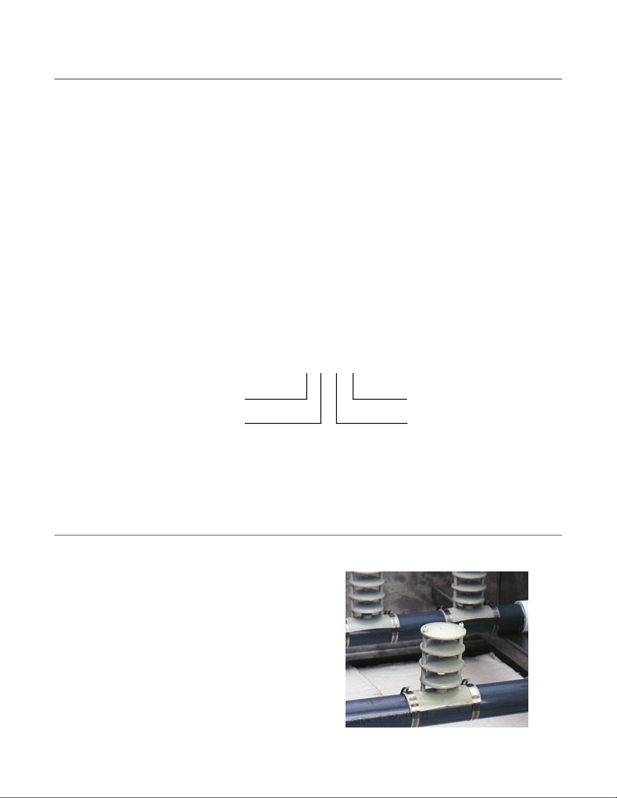
VIBRATION ISOLATORS
Spring type vibration isolator rails may be supplied for field
installation, most units will require an intermediate rigid steel
framework between the isolators and the base of the unit to
provide adequate structural support for the unit. Consult Recold
sales representative for recommendations on any vibration isolation
application.
STAINLESS STEEL CONSTRUCTION
300 stainless steel construction is offered as an option for sump
pan and upper casing panels.
RECOLD PRODUCTS
550 W MERCURY LANE
BREA, CALIFORNIA 92821
UNITED STATES
704 529 6080
info@recold.com
spxcooling.com
In the interest of technological progress,
all products are subject to design and/or
material change without notice.
©2008 SPX Cooling Technologies, Inc.
Printed in USA | RECOLD JW-TECH-08
 Loading...