

Page 1
Marley MS Cooling Tower
/
/
Page 2
SPX COOLING
TECHNOLOGIES
SPX Cooling Technologies has
worldwide recognition as the
pacesetter in the eld of water
cooling technology. Unique
within its industry in the scope of
products and services offered,we
design and manufacture cooling
towers of virtually any capacity
and conguration. More than
400 Marley tower models are
available to service the application
requirements of air conditioning,
industrial processing and electric
generation. More simply stated,
there’s a Marley cooling tower for
almost any conceivable water
cooling need — from as little as
15 gallons per minute to more
than 300,000 gallons per minute.
Page 3
Page 4

Page 5

Page 6
Page 7

Page 8

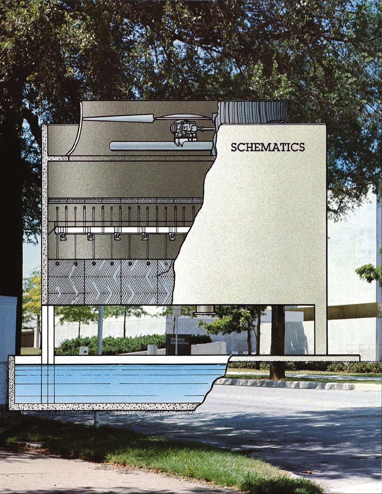
COMPONENTS
FILL: Marley MC high
performance PVC lm ll sheets
are thermoformed at the Marley
factory to exacting quality and
strength standards. Maximum
performance and clog resistant
designs are both available for
a wide range of thermal and
water quality requirements.
ELIMINATORS: Marley XCEL
®
drift eliminator panels—formed
from PVC sheets into a cellular
conguration—offer the lowest
drift rates in the industry.
They signicantly lower air
pressure losses, reducing fan
horsepower requirements.
Page 9

GEAREDUCERS: Marley
Geareducer
®
drives are the
industry quality standard. They
are designed to meet or exceed
the requirements of CTI STD-111
and AGMA Std, 420.4, and are run-
in under load prior to shipment.
Numerous reduction ratios are
available so that horsepower is
applied at optimum fan speed.
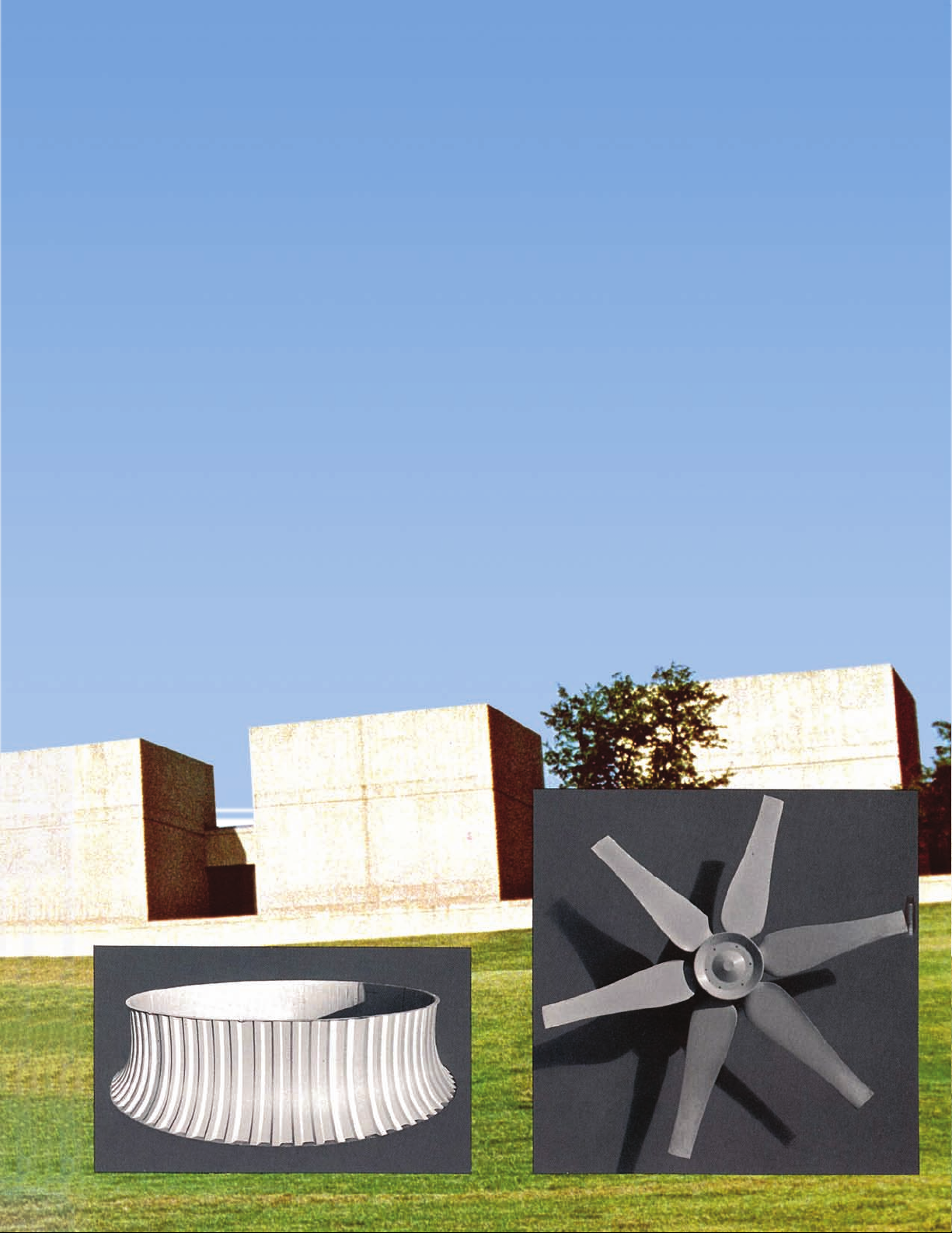
FANS: Designed, tested and
manufactured by Marley, fan
materials include cast aluminum
alloy, glass reinforced polyester
and glass reinforced epoxy. Fan
sizes and materials are selected
to be compatible with individual
application requirements.
DRIVESHAFTS: Rugged Marley
manufactured driveshafts are
built from stainless steel or carbon
ber composite tubes with
stainless steel anges. All Marley
driveshafts are dynamically
balanced at the factory to
minimize operating vibrations.
Page 10
MECHANICAL EQUIPMENT
SUPPORT: The Marley hot-
dipped galvanized torque
tube unitized support assures
permanent alignment of the motor,
driveshaft and Geareducer.
FAN CYLINDERS: Marley FRP
fan cylinders feature venturi
shaped eased inlets and close
fan tip clearance for maximum
efciency. If required, a concrete
fan cylinder may be utilized.
DISTRIBUTION SYSTEM: Marleypatented non-clogging, large
diameter NS spray nozzles assure
an unimpeded, uniform ow
with min-imal operating pump
head. Plus, they free you from
the expense and nuisance of
cleaning clogged nozzles.
STRUCTURE: Normal structure
consists of 8" thick concrete
exterior walls and interior cell
partitions. Cast-in-place fan decks
are normally 6" slabs. A furnished
torque tube spans the full fan deck
opening for mechanical equipment
support, thereby avoiding
concrete beam obstructions.
Page 11

SPECIFICATIONS
COOLING TOWER: Furnish and install (1) Induced
Draft Counterflow Cooling Tower. Cooling tower
shall be______ft. long x ______ft. wide x ______ ft.
overall height with a maximum operating weight
of______lbs. Cooling tower shall consist of_____fan
cells with a maximum of_____total fan horsepower
and a maximum pump head of______ft.
Other contractor(s) will furnish all external piping,
valves, pumps, electrical equipment other than
cooling tower fan motors, wiring, controls, etc. all in
accordance with general overall dimensions to be
supplied by cooling tower manufacturer. All internal
components of cooling tower as described following
will be furnished and installed by the cooling tower
manufacturer.
CAPACITY: Cooling tower shall be selected and
gua rante ed to cool__ _ ___GP M of wate r from
______°F to ______°F at ______°F entering wet bulb
temperature.
MECHANICAL EQUIPMENT: Mechanical equipment
shall be designed specically for cooling tower usage
and shall be mounted on a rigid unitized HDG steel
support to assure permanent drivetrain alignment.
Cooling tower manufacturer shall be responsible for
equipment warranty.
FANS: Fans shall be of a multi-blade propeller
type and blades shall be constructed of solid glass
reinforced polyester, cast aluminum alloy or hollow
glass reinforced epoxy. Hubs shall be HDG steel cast
iron or aluminum plate. Blades shall be individually
adjustable for required pitch angles.
DRIVESHAFTS: Driveshaft tubes and anges shall be
manufactured of type 304 stainless steel. Couplings
shall be hot dip galvanized cast iron, joined to
the driveshaft by exible neoprene bushings and
cadmium plated steel inserts. Connecting hardware
shall be 300 stainless steel. Driveshaft assemblies shall
be dynamically balanced at the factory at full motor
speed.
SPEED REDUCERS: Speed reducers shall be provided
for right angle fan drive and shall be designed to
AGMA standards for continuous duty opera tion,
capable of reverse operation. Oil ll and drain lines
are to be extended outside the fan cylinder to an oil
level sight glass.
ELECTRIC MOTORS: Electric motors shall be_______
speed, single winding, variable torque, _____ hp
maximum, TEFC, and specially insulated for cooling
tower duty. Speed and electrical characteristics shall
be _____ RPM, _____ phase, _____ hertz, _____ volts.
If the load applied to the motor exceeds 90% of the
nameplate rating, then the motor shall have a 1.15
service factor and the service factor beyond 1.0 shall
not be considered available for load.
FILL: Heat transfer ll media shall be crosscorrugated
20 mil PVC sheets supported by stainless steel tubes
which, in turn, are suspended by stainless steel tension
hangers from concrete support beam members.
DRIFT ELIMINATORS: Drift elimina tors shall be
supplied in a 3 pass cellular arrangement of bonded
17 mil PVC sheets. Drift loss shall not exceed ______%
of circulating water.
HOT WATER DISTRIBUTION SYSTEM: Hot water
distribution system in each cell shall be supplied with
a single interior inlet terminating 1'-0 below bottom of
the tower lling. Materials will be of inert PVC and RTR
and polypropylene piping supported by the support
beams utilized to carry heat transfer ll media.
FAN CYLINDERS: Fan cylinders shall have eased inlet
design and be of molded ber reinforced polyester
with a minimum height of 6' 0.
OPTlONS: Factory Mutual Approval. The tower
shall include all design and material modications
necessary to meet the re rating requirements of
Factory Mutual. The product proposed shall be listed
in the FM Approval Guide, latest edition.
Masonry structure options at owner’s election:
1-Shell structure design shall be by cooling tower
manufacturer.
2-Shell structure and cold water basin design shall be
by cooling tower manufacturer.
3-Shell structure and cold water basin design shall
be by cooling tower manufacturer. Shell structure
construction including materials and labor shall be
by cooling tower manufacturer.
4-Shell structure and cold water basin design shall be
by cooling tower manufacturer. Shell structure and
cold water basin construction including materials and
labor shall be by cooling tower manufacturer.
WARRANTY: Warranty on all components against
de fective ma t eri als and workmans hip will be
extended for a period of one (1) year following initial
operation but not exceeding eighteen (18) months
from date of shipment. Components that may fail
within warranty period shall be repaired and/or
replaced including freight and installation labor.
Thermal testin g of cooling tower will be done
within one (1) year following structural completion
in accordance with Cooling Technolog y Institute
Acceptance Test Code CTI ATC 105. In the event test
results indicate deciency, manufacturer shall make
alterations to overcome indicated deciency and if
such alterations are inadequate manufacturer shall
refund a percentage of contract price proportional to
tower deciency.
Page 12

7401 WEST 129 STREET
OVERLAND PARK, KANSAS 66213
UNITED STATES
913 664 7400
spxcooling@spx.com
spxcooling.com
In the interest of technological progress,
all products are subject to design and/or
material change without notice.
©2008 SPX Cooling Technologies, Inc.
Printed in USA | MS-06
 Loading...