

Page 1

Springer Tracts in Mechanical Engineering
Yong Chen
Automotive
Transmissions
Design, Theory and Applications
Page 2

Springer Tracts in Mechanical Engineering
Series Editors
Seung-Bok Choi, College of Engineering, Inha University, Incheon, Korea
(Republic of)
Haibin Duan, Beijing University of Aeronautics and Astronautics, Beijing, China
Yili Fu, Harbin Institute of Technology, Harbin, China
Carlos Guardiola, CMT-Motores Termicos, Polytechnic University of Valencia,
Valencia, Spain
Jian-Qiao Sun, University of California, Merced, CA, USA
Young W. Kwon, Naval Postgraduate School, Monterey, CA, USA
Page 3

Springer Tracts in Mechanical Engineering (STME) publishes the latest developments in Mechanical Engineering - quickly, informally and with high quality. The
intent is to cover all the main branches of mechanical engineering, both theoretical
and applied, including:
• Engineering Design
• Machinery and Machine Elements
• Mechanical Structures and Stress Analysis
• Automotive Engineering
• Engine Technology
• Aerospace Technology and Astronautics
• Nanotechnology and Microengineering
• Control, Robotics, Mechatronics
• MEMS
• Theoretical and Applied Mechanics
• Dynamical Systems, Control
• Fluids Mechanics
• Engineering Thermodynamics, Heat and Mass Transfer
• Manufacturing
• Precision Engineering, Instrumentation, Measurement
• Materials Engineering
• Tribology and Surface Technology
Within the scope of the series are monographs, professional books or graduate
textbooks, edited volumes as well as outstanding PhD theses and books purposely
devoted to support education in mechanical engineering at graduate and
post-graduate levels.
Indexed by SCOPUS. The books of the series are submitted for indexing to
Web of Science.
Please check our Lecture Notes in Mechanical Engineering at http://www.springer.
com/series/11236 if you are interested in conference proceedings.
To submit a proposal or for further inquiries, please contact the Springer Editor in
your country:
Dr. Mengchu Huang (China)
Email: mengchu.Huang@springer.com
Priya Vyas (India)
Email: priya.vyas@springer.com
Dr. Leontina Di Cecco (All other countries)
Email: leontina.dicecco@springer.com
More information about this series at http://www.springer.com/series/11693
Page 4

Yong Chen
Automotive Transmissions
Design, Theory and Applications
123
Page 5

Yong Chen
Hebei University of Technology
Tianjin, China
ISSN 2195-9862 ISSN 2195-9870 (electronic)
Springer Tracts in Mechanical Engineering
ISBN 978-981-15-6702-5 ISBN 978-981-15-6703-2 (eBook)
https://doi.org/10.1007/978-981-15-6703-2
Jointly published with China Machine Press
The print edition is not for sale in China (Mainland). Customers from China (Mainland) please order the
print book from: China Machine Press.
ISBN of the Co-Publisher’s edition: 978-7-111-59945-6
© China Machine Press and Springer Nature Singapore Pte Ltd. 2021
This work is subject to copyright. All rights are reserved by the Publishers, whether the whole or part
of the material is concerned, specifically the rights of translation, reprinting, reuse of illustrations,
recitation, broadcasting, reproduction on microfilms or in any other physical way, and transmission
or information storage and retrieval, electronic adaptation, computer software, or by similar or dissimilar
methodology now known or hereafter developed.
The use of general descriptive names, registered names, trademarks, service marks, etc. in this
publication does not imply, even in the absence of a specific statement, that such names are exempt from
the relevant protective laws and regulations and therefore free for general use.
The publishers, the authors, and the editors are safe to assume that the advice and information in this
book are believed to be true and accurate at the date of publication. Neither the publishers nor the
authors or the editors give a warranty, express or implied, with respect to the material contained herein or
for any errors or omissions that may have been made. The publishers remain neutral with regard to
jurisdictional claims in published maps and institutional affiliations.
This Springer imprint is published by the registered company Springer Nature Singapore Pte Ltd.
The registered company address is: 152 Beach Road, #21-01/04 Gateway East, Singapore 189721,
Singapore
Page 6

Foreword
Professor Chen Yong has been engaged in the research and development of
automotive transmissions for a long time. He worked in the world famous automatic transmission company (JATCO) of Nissan Motor for 19 years, and completed
the development and mass production of many automatic transmission products;
after that, he worked in domestic automobile enterprises for nine years, leading the
independent research and development of manual and automatic transmissions of
Geely Automobile, and achieved fruitful results; now, he is devoted to academic
study in colleges and universities and committed to sorting out and systematically
refining his practical experience and technical accumulation of transmission
research over 30 years, and sharing it with others so as to benefit the industry and
help the development and progress of China’s automotive transmission business.
The book Theory, Design and Application of Automotive Transmissions of the
leading coauthor Chen Yong accumulates the profound knowledge and valuable
experience of first-class transmission experts and scholars at home and abroad,
elaborates the international advanced technology and development trend of automotive transmissions and emphatically explains the mature design theory in the
automotive transmission field and the latest international research and application
progress. It can be used as an engine ering technical book for automotive and
transmission R&D engineers and a reference book for graduates and undergraduates to learn basic theories and carry out academic research. It is a rare masterpiece
of both theory and practice.
Zhao Fuquan
Rotating Chairman of FISITA (2018–2020)
President of Automotive Industry
and Technology Strategy Institute
Tsinghua University, China
v
Page 7

Preface
In order to change the output torque and speed of the engine and other power
systems, it is usually necessary to install a transmission in the transport machinery.
This book deals mainly with the transmissions of road vehicles. Under different
driving conditions, such as standing start, climbing, turning and acceleration, the
torque and speed required by the driving wheel of the vehicle are constantly
changing, while the range of torque and speed change that the engine can provide is
limited. The transmission is to adjust the performance of the engine by changing the
gear ratio and transfer the engine power to the wheels smoothly, reliably and
economically, so as to adapt well to the demands of external load and road conditions and achieve the best match between the characteristic field provided by the
engine and that required by the vehicle.
The automotive transmission is a high technology and process level of typical
products in mass production, and its development and design shall be oriented to
market demands while meeting environmental and regulatory requirements.
Regulatory requirements (such as energy conservation and emissions policies) and
user requirements must be fully considered. The main design objective of the
automotive transmission is to achieve the optimal transformation from engine or
motor power to the vehicle driving force within the wide speed range of the vehicle,
so as to ensure the dynamic property, acceleration and fuel economy of the vehicle.
Meanwhile, the application reliability and service life of new technologies and
processes shall be considered. The transmission design will be increasingly challenging given the increasing demand for fuel consumption, emissions and driveability, especially shift comfort and response speed. The current types of
transmission for passenger vehicles, including Manual Transmission (MT),
Automatic Transmission (AT), Dual Clutch Transmission (DCT), Continuously
Variable Transmission (CVT) and Automated Mechanical Transmission
(AMT) will remain largely unchanged for a long time. However, the application of
hybrid transmissions will grow substantially. The first author of this book worked
as a senior technician in the AT&CVT R&D in the R&D center of JATCO in Japan
for 19 years and was in charge of the R&D of AT and MT in Geely Automobile for
a long time after returning from abroad. He was deeply aware of the rapid progress
vii
Page 8

viii Preface
of transmission technology and accelerated R&D cycle brought by computer
simulation techno logy, and also deeply aware of the urgent demand for systematic
explanation of the transmission development technology in the research and
development.
Therefore, the main purpose of this book is to systematically summarize the
main technical areas of the MT and AT development technology based on practical
development experience, comprehensively elaborate the theory and development
characteristics of the transmissions and display the main development processes
of the transmissions. In particular, many development processes are based on the
experience of trial and error. As a reference book providing main technical information for the research and development of transmission technology, this book is
suitable for engineers working in the field of automobiles and related power
transmission machines and graduate students at school. I would also like to thank
Dr. Guo Lishu, senior technical expert of Geely Commercial Vehicle Research
Institute, Dr. Gao Bingzhao of the College of Automotive Engineering, Jilin
University, for their hard work in this book. I would like to thank Dr. Tian Hua
from SGM Powersoon Research Institute, my doctoral student Zang Libin, Qiu
Zizhen, Li Guangxin, Wei Changyin, my assistant Cao Zhan and other graduate
students from the NEV Research Center of the Hebei University of Technology, as
well as others who have worked hard for this book. I would like to thank the Tianjin
Science and Technology Association for subsidizing this book.
Tianjin, China Yong Chen
Page 9

Contents
1 Introduction .......................................... 1
1.1 Transmission Functions and Requirements
1.2 Types, Advantages and Disadvantages of Transmissions
1.3 Basic Structure of Transmission
........................ 12
1.4 Development Status and Trend of Transmission
Bibliography
.......................................... 21
................ 2
...... 3
............ 14
2 Manual Transmission
2.1 Overview
................................... 23
........................................ 23
2.2 Transmission Drive Mechanism
2.3 Synchronizer
..................................... 26
2.4 Transmission Operating Mechanism
2.5 Determination of Gear Ratio
.......................... 42
2.6 Joint Working of Engine and Transmission
2.7 Shift Performance Evaluation
2.8 New Technologies of MT
Bibliography
.......................................... 60
3 Automatic Transmission
3.1 Overview
........................................ 61
................................. 61
......................... 54
............................ 54
3.2 Composition and Control Principle of AT
3.3 Mechanical Structure of AT
.......................... 66
3.4 AT Speed Change Process Analysis
3.5 Hydraulic Control System of AT
3.6 Electronic Control System of aT
3.7 AT Performance Tests
3.8 Development Direction of aT
Bibliography
.......................................... 108
............................... 99
......................... 103
........................ 23
..................... 38
............... 49
................ 63
..................... 78
....................... 84
....................... 98
ix
Page 10

x Contents
4 Continuously Variable Transmission ........................ 109
4.1 Overview
4.2 Composition of CVT
........................................ 109
............................... 111
4.3 Composition and Drive Theory of VDT Belt .............. 117
4.4 Composition and Principle of Hydraulic Control System
4.5 CVT Electronic Control System
4.6 Control of CVT
................................... 145
4.7 Main Performance Tests of Metal Belt CVT
4.8 CVT Upgrade
Bibliography
..................................... 148
.......................................... 153
........................ 140
............... 145
...... 129
5 Dual Clutch Transmission
................................ 155
5.1 Overview ........................................ 155
5.2 System Composition and Working Principle of DCT
5.3 Typical Design Scheme of DCT
5.4 Dual Clutch
5.5 Select-Shift Actuator
...................................... 162
................................ 177
5.6 Hydraulic Control System
5.7 Control System Hardware Design
5.8 Control System Software Design
....................... 159
............................ 180
...................... 190
....................... 195
........ 157
Bibliography .......................................... 199
6 Automated Mechanical Transmission
6.1 Overview
........................................ 201
....................... 201
6.2 Composition and Working Principle of AMT Control
System
.......................................... 202
6.3 Shifter .......................................... 207
6.4 Clutch
6.5 Select-Shift Actuator
6.6 Hydraulic Control System
6.7 AMT Control Strategy
6.8 AMT Performance Evaluation Indexes
Bibliography
7 Transmission for New Energy Vehicle
7.1 Overview
7.2 Power and Economy Performance of HEV
7.3 AMT Hybrid Transmission
7.4 AT Hybrid Transmission
7.5 CVT Hybrid Transmission
7.6 DCT Hybrid Transmission
7.7 Planetary Gear Hybrid Transmission
7.8 Electric Vehicle Transmission
7.9 Other Hybrid Power Plants
Bibliography
.......................................... 210
................................ 214
............................ 217
.............................. 222
................... 227
.......................................... 232
...................... 233
........................................ 233
................ 235
........................... 240
............................. 243
............................ 248
............................ 254
.................... 257
......................... 261
........................... 267
.......................................... 271
Page 11

Contents xi
8 Transmission Design .................................... 273
8.1 Gear Design
8.2 Shaft Design
...................................... 273
...................................... 292
8.3 Bearing Selection and Design ......................... 297
8.4 Case Design
8.5 Parking Mechanism Design
8.6 Synchronizer Design
8.7 Selection of Seals
8.8 Transmission Ventilation Design
8.9 Transmission Tests
Bibliography
...................................... 300
........................... 308
................................ 328
.................................. 345
....................... 350
................................. 351
.......................................... 356
9 Transmission Fluid
9.1 MTF
9.2 ATF
........................................... 357
............................................ 358
9.3 CVTF
9.4 DCTF
..................................... 357
.......................................... 358
.......................................... 360
9.5 Performance Requirements and Tests for Transmission
Fluid
........................................... 362
9.6 Selection of Transmission Fluid
........................ 366
Bibliography .......................................... 369
10 Design of Hydraulic Torque Conve rter
...................... 371
10.1 Working Principle and Characteristics of Hydraulic Torque
Converter
10.2 Pre-design of Hydraulic Torque Converter
........................................ 371
................ 383
10.3 Blade Shape Design ................................ 391
10.4 Numerical Simulation and Analysis of Internal Flow Field
of Hydraulic Torque Converter
10.5 Parameter Adjustment of Hydraulic Torque Converter
10.6 Hydraulic Torque Converter Matching with Engine
Bibliography
11 Planetary Gear Drive
.......................................... 435
................................... 437
........................ 409
........ 428
......... 432
11.1 Theoretical Calculation of Transmission Efficiency
of Planetary Gear Train
11.2 Transmission Efficiency Test of Planetary Gear Train
.............................. 439
........ 454
11.3 Theoretical Calculation of Vibration and Noise
of Planetary Gear Train
11.4 Vibration and Noise Test of Planetary Gear Train
Bibliography
.......................................... 483
.............................. 464
........... 470
12 Electronic Control System of Auto matic Transmission
12.1 Introduction to AT Electronic Control System
12.2 AT Control System Development
...................... 488
............. 485
.......... 485
Page 12

xii Contents
12.3 Validation of System Validity ......................... 503
12.4 Control Strategies of AT
............................. 506
12.5 Modeling of Hydraulic Torque Converter with Lockup
Clutch
12.6 Lockup Clutch Oil Circuit
.......................................... 507
............................ 508
12.7 Study on Control Strategies for Lockup Process of Lockup
Clutch
Bibliography
.......................................... 510
.......................................... 532
13 Automobile and Transmission Vibration and Noise
13.1 Vibration and Noise Foundation
13.2 Automobile Vibration and Noise
....................... 533
....................... 537
............ 533
13.3 Typical Automobile Vibration and Noise ................. 545
13.4 Analysis of Transmission Vibration and Noise
13.5 Typical Transmission Vibration and Noise Control
Bibliography
.......................................... 569
............. 553
.......... 563
Page 13

Chapter 1
Introduction
Since the small torque range of the automobile engine cannot adapt to the requirements of automobile driving under various road conditions, the transmission that can
change the speed ratio and drive torque is adopted in the automotive drivetrain to
make the torque and speed output by the engine and other power systems vary in
a considerable range. This book deals mainly with the transmissions of road vehicles. Under different driving conditions, such as standing start, climbing, turning
and acceleration, the torque and speed required by the driving wheel of the vehicle
are constantly changing, while the range of torque and speed change that the engine
can provide is limited. The transmission is to adjust the performance of the engine
by changing the gear ratio and transfer the engine power to the wheels smoothly,
reliably and economically, so as to adapt well to the demands of external load and
road conditions and achieve the best match between the characteristic field provided
by the engine and that required by the vehicle.
The automotive transmission is a high technology and process level of typical
products in mass production, and its development and design shall be oriented to
market demands and fully consider the user requirements while meeting environmental and regulatory requirements (such as energy conservation and emissions
policies), as shown in Fig. 1.1. The main design objective of the automotive transmission is to achieve the optimal transformation from engine or motor power to the
vehicle driving force within the wide speed range of the vehicle, so as to ensure
the dynamic property, acceleration and fuel economy of the vehicle. Meanwhile,
the application reliability and service life of new technologies and processes shall
be considered. The transmission design will be increasingly challenging given the
increasing demand for fuel consumption, emissions and driveability, especially shift
comfort and response speed. The current types of transmission for passenger vehicles, including manual transmission (MT), automatic transmission (AT), continuously variable transmission (CVT), dual clutch transmission (DCT) and automated
mechanical transmission (AMT) will remain largely unchanged for a long time.
However, the hybrid transmissions will be more widely used and their number will
increase dramatically. The author of this book worked as a senior technician in the
© China Machine Press and Springer Nature Singapore Pte Ltd. 2021
Y. C h e n, Automotive Transmissions, Springer Tracts in Mechanical Engineering,
https://doi.org/10.1007/978-981- 15-6703-2_1
1
Page 14
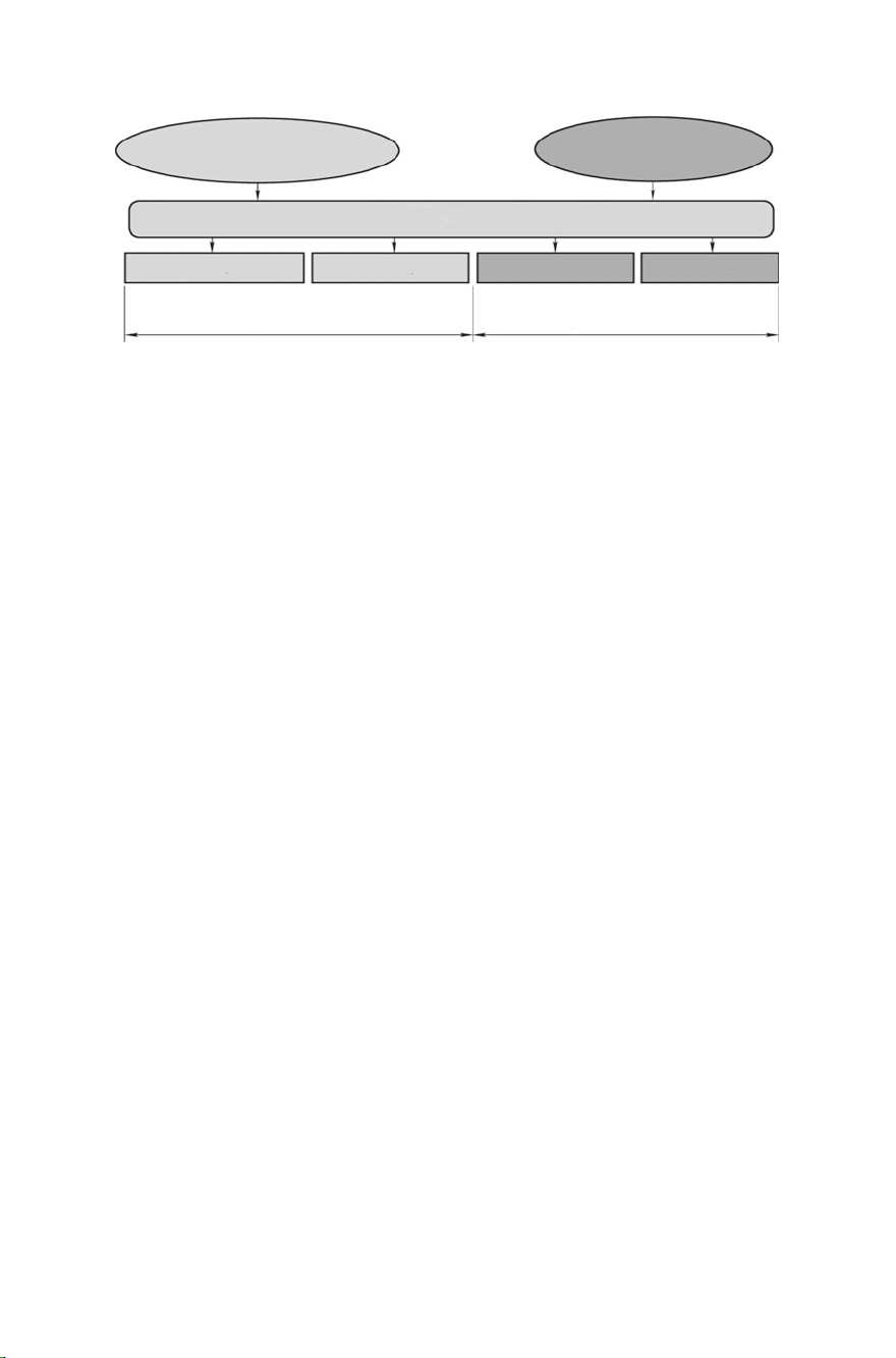
2 1 Introduction
Consumer demands: comfort and economy
Apply more advanced and efficient technology
Wide speed ratio and
multiple gears
Shift smoothness and economy
Fig. 1.1 Transmission design requirements
Shift strategy
optimization
Regulatory requirements: low-carbon,
efficient and environmentally friendly
Improve transmission
efficiency
Low-carbon, efficient and environmentall
Lightweight design
y friendly
AT&CVT R&D in the R&D center of JATCO in Japan for 19 years and was in charge
of the R&D of AT and MT in Geely Automobile for a long time after returning from
abroad. He was deeply aware of the rapid progress of transmission technology and
accelerated R&D cycle brought by computer simulation technology, and also deeply
aware of the urgent demand of the R&D personnel for systematic explanation of the
transmission development technology.
Based on the author’s over 30 years of practical experience in the development of
automotive transmissions at home and abroad, this book systematically summarizes
the main technical areas of the MT and AT development technology, comprehensively elaborates the theory and development characteristics of the transmissions
and displays the main development processes of the transmissions. Many development processes are based on the experience of trial and error. As a reference book
providing main technical information for the research and development of transmission technology, this book is suitable for engineers in the field of automobiles and
related power transmission machines and graduate students at school.
1.1 Transmission Functions and Requirements
The function of the transmission is to change the torque and speed of the engine
according to the requirements of the vehicle in different driving conditions, so that
the vehicle has the right traction and speed, and keeps the engine working in the most
favorable working conditions. To ensure the vehicle reversing and the powertrain
separation, the transmission must have forward as well as reverse and neutral. When
power output is required, power output devices shall also be provided.
Main requirements for the transmission:
(1) Guarantee good dynamic and economic indicators of the vehicle. This require-
ment is met by choosing the appropriate transmission gear number and gear
ratio according to the vehicle dead weight capacity, engine performance parameters, tire performance parameters and vehicle use requirements in the overall
vehicle design.
Page 15

1.1 Transmission Functions and Requirements 3
(2) Reliable work and easy control. Automatic gear dropping, gear mixing and
shift impact are not allowed in the transmission during the vehicle driving.
(3) High safety. Guarantee the safe and reliable vehicle driving in any working
conditions.
(4) Small in size and light in weight. This requirement is met by reasonable use of
engineering plastics and other non-metallic materials, and the use of advanced
material forming technology and heat treatment technology.
(5) Low cost. Minimize the cost under the premise of meeting the vehicle
requirements for the transmission.
(6) High transmission efficiency. In order to reduce the gear engagement loss and
bearing friction loss, it is necessary to improve the manufacture and assembly
quality of components and reduce the gear churning loss. For example, the
proper lubricating oil and installed capacity can be selected to reduce the
churning loss and friction loss, thus improving the transmission efficiency.
(7) Low noise. This requirement can be met by adopting helical gears, selecting
a reasonable modification coefficient, making the axial modification and
profile modification and improving the manufacturing accuracy and assembly
stiffness.
(8) Meet the maximum input torque requirements.
(9) Meet the drive mode requirements.
(10) Meet the vehicle layout and installation requirements.
(11) Meet the reliable ramp parking requirements except for the MT.
(12) Meet the limp home requirements.
(13) With respect to the electrical controlled transmission, the hardware of the
control system shall meet the requirements of electromagnetic compati-
bility and anti-interference, and the software shall meet the requirements of
ISO26262, ASPICE, AUTOSAR and other standards.
(14) Consider factors such as driving pleasure and shift comfort and minimize the
shift impact.
1.2 Types, Advantages and Disadvantages of Transmissions
I. Types of automotive transmissions
Depending on the fixation of the gear ratio, the transmission may be classified into
stepped transmission and continuously variable transmission (CVT). The stepped
transmission, with fixed gear ratio, including ordinary transmission and planetary
transmission, is gear-driven and mostly widely used; the CVT, with the gear ratio
changing in a certain range, includes electric and hydraulic types. The variable speed
drive component of the electric CVT is DC series motor and the drive component of
the hydraulic CVT is hydraulic torque converter. The CVT can overcome the sudden
shift, slow throttle response, high fuel consumption and other shortcomings of the
AT and is mostly used in trolley buses and heavy-duty vehicles.
Page 16
4 1 Introduction
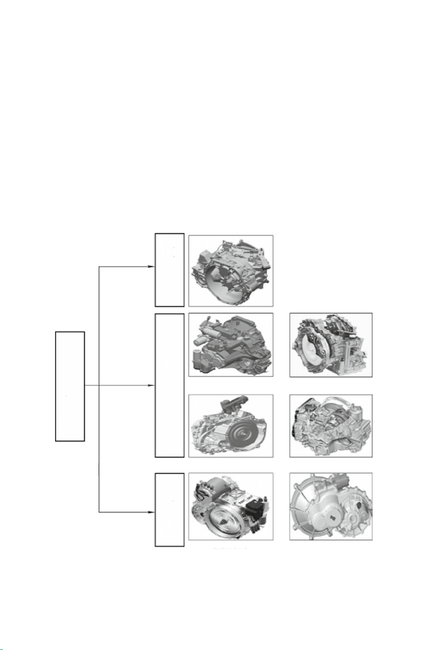
The transmissions used in the passenger vehicles currently include MT, AT, CVT,
DCT, AMT and VIT, as well as the BEV transmission and HEV transmission evolved
on the basis of the above transmissions, as shown in Fig. 1.2.
1. Manual transmission
Manual transmission (MT) is also known as mechanical transmission. The engaging
position of the gears in the transmission is changed by moving the gear shift lever
by hand, thus changing the gear ratio to achieve variable speed. It take a place
in the transmission family because of its high transmission efficiency, high torque
transfer, easy manufacture, low cost, simple structure, low fuel consumption, short
acceleration time and short development cycle. The current MT is mainly 5 speed or
6 speed MT, covering SUV, middle-sized vehicles and compact vehicles. In order to
reduce fuel consumption and improve driving pleasure, the transfer torque increases
MT
Drive
system
AT
NEV
transmi
ssion
HEV transmission BEV transmission
Fig. 1.2 Main types of transmissions for passenger vehicles
AMT CVT
DCT
AT
Page 17

1.2 Types, Advantages and Disadvantages of Transmissions 5
step by step and the 6 speed transmission in the MT will become the mainstream.
ZF and BMW are developing the 7 speed MT currently.
2. Automatic transmission
The automatic transmission (AT) is also known as stepped AT. According to the
different arrangement modes of shafts, AT can be divided into fixed shaft AT and
rotating shaft AT. Due to the large space occupied by the fixed shaft (parallel shaft),
it is impossible to achieve more gears (limited to 5-speed and 6-speed), which is
currently the main technology of Honda. The vastmajority of transmission companies
use the rotating shaft technology solutions. AT may be divided into 4AT, 5AT, 6AT,
7AT, 8AT and 9AT by gear. GM, Volkswagen and other automotive companies have
begun to develop 10AT. With mature technology and small size, 4AT is still the main
AT carried by small cars, although its comfort and economy are poor; 5AT is slightly
better than 4ATin terms of comfort and economy,but has still obvious abrupt shift and
limited late development space; 6AT has relatively superior economy and comfort
and has become a mainstream trend for small, compact and middle-sized vehicles;
7AT and 8AT have been adopted by Lexus, BMW, Audi, Benz and other highend imported models. 8AT has been successfully developed by domestic Shengrui
Transmission Co., Ltd. and installed in Landwind; 9AT represents the innovation of
science and technology has been developed successfully by ZF and Aisin Seiki.
3. Continuously variable transmission
The continuously variable transmission (CVT) becomes an important branch of automotive automatic transmission field since it can produce continuously changing gear
ratio, achieve the best match between the engine and powertrain, simplify the operation, reduce the driver’s labor intensity, increase driving safety, driving smoothness
and comfort and improve emission. CVT is classified into metal pushing V-belt type
CVT, chain type CVT and KRG. With light weight, small volume, simple s tructure,
smooth shift, relatively high cost, inconvenient maintenance and limited carrying
capacity, the metal pushing V-belt type CVT is used in small and compact cars and
has more room for improvement because of its unparalleled comfort. The chain type
CVT is the main technology of Schaeffler in terms of CVT and has higher transmission efficiency and more compact structure than the metal pushing V-belt type CVT,
but its disadvantage is that the protruding pin on the side of the chain will produce
noise when it comes into contact with the pulley point. At present, the KRG may be
unfamiliar to most people, but this kind of transmission may become the mainstream
transmission for low-emission vehicles in the future. Its low cost, high efficiency,
simple structure and multiple advantages in function and comfort deserve people’s
attention.
4. Dual clutch transmission
The dual clutch transmission (DCT), as a new AT, arranges the transmission gears by
odevity respectively on the two input shafts connected with two clutches, completes
Page 18

6 1 Introduction
the shift process and achieves power shift through the alternate switching of clutches.
DCT has the advantages of AT and AMT. With high transmission efficiency, simple
structure and low production cost, it guarantees the dynamic and economy performance of the vehicle and greatly improves the vehicle operating comfort. DCT is
divided into DDCT and WDCT. DDCT is also divided into electro-hydraulic DDCT
and electric DDCT. The former is complicated in structure, needs to be improved
in reliability and is used in Volkswagen vehicles; the latter is simple and reliable
in structure and will become the mainstream trend in the development of small and
medium torque AT in the future. With large carrying capacity, WDCT will be used
greatly in the intermediate class and above vehicles.
5. Automated mechanical transmission
The automated mechanical transmission (AMT), based on the traditional fixed shaft
transmission, controls the hydraulic or electric actuating system through the electronic control unit by use of the electronic technology and automatic transmission
theory to achieve the clutch disengagement and engagement, gear selecting and
shifting, so as to achieve the automatic control of start and shift. AMT has a certain
development space in mini and small cars due to its high transmission efficiency,
easy manufacturing and low cost, but it has not much development space in models
above the compact level due to power failure in the shift process.
The AMT usually consists of electrically controlled hydraulic AMT and electrically driven AMT. The AMT with the core of electro-hydraulic actuator in the
electrically controlled hydraulic AMT has been widely applied in Chery QQ3, Riich
M1, Chevrolet Sail, SAIC MG3 and other models; compared with the electrically
controlled hydraulic AMT, the electrically driven AMT has simpler structure, better
reliability and lower cost and is the mainstream trend of AMT development.
6. Vit
VIT is a new concept of high-power and high-efficiency mechanical CVT successfully developed on the basis of the meshing principle of sliding vane CVT movable
teeth. The working surface of the sliding vane CVT movable teeth is overlapped by
a series of sliding vanes and any shape of meshed tooth profile can be formed by
free stepless slip of the sliding vanes. This design idea is equivalent to the “differentiation and reintegration” of the gears. That is, any required tooth profile, i.e. the
sliding vane CVT movable teeth can be formed by organic combination of multiple
elements. Since the slip direction of the sliding vanes is different from the force direction, the sliding vanes are free to deform with the current meshed tooth profile, while
the force direction is perpendicular to the free slip direction or the angle between
them is self-locking in the equivalent friction angle during the power transmission.
Therefore, the sliding vanes will not change the shape of the tooth profile when
bearing force. With the “rigid and flexible fusion, and movable teeth solidification”
effect, high carrying capacity and transmission efficiency, VIT is the true sense of
“movable teeth meshing CVT” and is applied in saloon cars, passenger cars, trucks
and other high-power and high-torque vehicles.
Page 19
1.2 Types, Advantages and Disadvantages of Transmissions 7
7. BEV transmission
The BEV transmission mainly includes single reduction gear, multi-speed transmission and the wheel-side drive motor integrating reducer and motor. At present,
the single speed reducer with fixed speed ratio is mostly used in the small electric vehicles. This drive mode has simple structure and low manufacturing cost, but
it puts forward higher requirements for the traction motor that the traction motor
shall provide higher instantaneous torque in the constant torque area and higher
running speed in the constant power area, so as to meet the vehicle acceleration
performance requirements and maximum speed design requirements. Meanwhile,
the single speed reducer with fixed speed ratio has the problem of low motor utilization efficiency. In order to ensure the maximum vehicle speed, the speed ratio of
the reducer is often relatively small, which makes the traction motor in a longterm high torque and high current working condition, and relatively low motor efficiency, thus wasting the battery energy and reducing the driving range. The electric
vehicle drivetrain tends to be multi-speed to make the electric vehicles better meet
their dynamic performance and reduce their requirements for traction motors and
batteries. Oerlikon Graziano developed a two-speed transmission to match small
electric vehicles. Antonov designed a new efficient 3 speed AT for BEV that optimizes the powertrain size, weight and development costs while improving the energy
efficiency and guaranteeing the dynamic performance.
8. HEV transmission
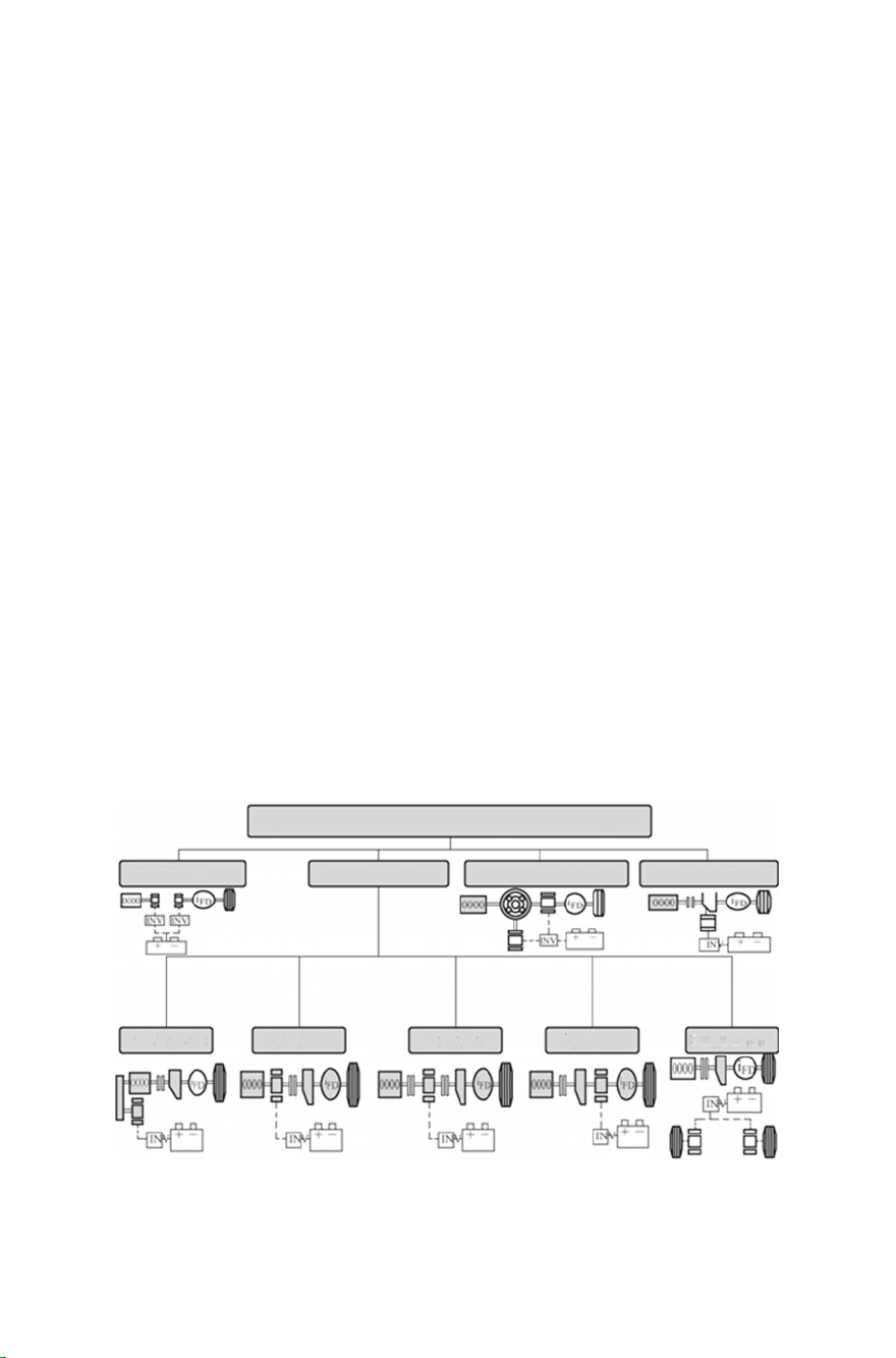
(1) Hybrid drive type: before introducing the HEV transmission, it is important
to know the hybrid drive type. As shown in Fig. 1.3, the hybrid drive mainly
includes tandem hybrid drive, parallel hybrid drive, power-split hybrid drive
and other hybrid drive.
Hybrid drive types
Tandem hybrid drive
P0 hybrid P4 hybrid
Fig. 1.3 Hybrid drive types
Parallel hybrid drive
P1 hybrid
Power-split hybrid drive
P2 hybrid
Other hybrid drive
P3 hybrid
Page 20

8 1 Introduction
(1) Tandem hybrid drive. The engine is completely decoupled from the driving
wheel and simply drives the generator to charge the power battery, which
drives another motor through the motor controller to keep the vehicle
moving. This scheme has low overall efficiency due to many power drive
links, but it is comfortable because the engine is completely decoupled
from the driving wheel.
(2) Parallel hybrid drive. Depending on the motor arrangement on the whole
vehicle, it is divided into P0 (BSG), P1 (ISG), P2, P3 and P4 structural
hybrid drives. In P0 structural hybrid drive, the motor is integrated in the
position of the generator of the traditional engine, playing the role of power
generation, assistance and starting, and acting as the generator in energy
recovery to recover the braking energy; in P1 structural hybrid drive, the
motor is integrated at the output end of the engine crankshaft, playing the
role of power generation, assistance and starting, and acting as the generator
in energy recovery to recover the braking energy; in P2 structural hybrid
drive, the motor is also integrated between the engine and the transmission.
The difference is that the motor is connected to the engine and transmission separately through the clutch, playing the role of power generation,
assistance and starting, and acting as the generator in energy recovery to
recover the braking energy. The motor drives the vehicle alone, either fully
hybrid or plug-in hybrid, which is one of the main forms of hybrid drive;
in P3 structural hybrid drive, the motor is integrated at the output end of
the transmission, playing the role of assistance and power generation, and
acting as the generator in energy recovery to recover the braking energy.
The motor drives the vehicle alone, either fully hybrid or plug-in hybrid;
in P4 structural hybrid drive, the engine drives a drive axle and the motor
drives the other drive axle. The motor plays the role of assistance and
power generation and acts as the generator in energy recovery to recover
the braking energy. The motor can also drive the vehicle alone, either fully
hybrid or plug-in hybrid.
(3) Power-split hybrid drive. It integrates the engine and two motors by means
of the planetary gear train to achieve various functions of the hybrid drive.
A typical example is Toyota Prius HEV, also known as the eCVT because
of the use of planetary gear train and motors to shift the output end of the
engine and planetary gear train.
(4) Other hybrid drive. A typical example is Honda Fit 7DCTH hybrid drive,
in which, the motor is connected to an input shaft of 7DCT through the
drive mechanism, forming a new and unique drive form. In this scheme, the
motor needs to be synchronously tracked in shift of each gear connected
with the motor input shaft, so as to reduce the difference between the active
and passive speeds of the synchronizer and prolong the service life of the
response synchronizer.
Page 21

1.2 Types, Advantages and Disadvantages of Transmissions 9
(2) Common transmissions on HEV: the traditional automotive transmissions are
used in HEVs, among which AT is more widely used, as follows:
The AMT is the ideal choice for HEV transmissions. The electrically driven transmission based on AMT is characterized by coupling the motor used in the NEV
with AMT through high-intensity silent chain drive, which solves the power failure
problem during shift. This new electrically driven transmission fully combines the
advantages of the motor and the AMT to significantly reduce fuel consumption. The
7H-AMT hybrid transmission developed by FEM based on AMT i s characterized by
that the drive motor transfers power through other gears and outputs a certain torque
in the upshift to eliminate the impact caused by power failure during shift.
The application schemes of AT in HEV include coupling the motor at the input
end of the transmission and coupling the motor at the output end of the transmission.
The recent new scheme is to replace the hydraulic torque converter of the AT with
motor.In these schemes, the lubrication system shall be improved and the mechanical
fuel pump of the traditional AT is replaced with an electronic fuel pump or a new
electronic fuel pump is added; otherwise, the EV mode will be difficult to meet the
system lubrication requirements and fast start-stop requirements.
CVT is most frequently used in the mass produced HEVs. The HEV AT is characterized by powertrain integration. That is, the motor is integrated with the transmission, making the system structure more compact, power drive more stable and
control performance better.
The applications of DCT in HEV mainly include that the drive motor is connected
to the input shaft 1 of the transmission through the reducing gear, that the drive motor
is connected to the input shaft 2 of the transmission through the reducing gear and
that the drive motor is connected to the input shaft of the transmission through the
reducing gear. The advantage of the first two schemes is that the motor drive can
change the speed, but the disadvantage is that the motor needs to be synchronously
tracked in the synchronous engagement of the gear of the input shaft connected to the
motor; the advantage of the latter scheme is that the motor may not be synchronously
tracked in the shift, but the disadvantage is that the motor drive cannot change speed.
In addition, the PRIUS hybrid power system is a typical example of PSHEV. The
biggest feature of this system is to use a planetary gear train to couple two motors
and an engine together, so that a single planetary gear train can realize the functions
of CVT. See Table 1.1 for typical hybrid transmission applications.
II. Advantages and disadvantages of transmissions
The transmission, as an important part of the vehicle powertrain system, determines
the power output of the vehicle and has a direct impact on the fuel economy, comfort
and reliability of the vehicle. Different types of transmissions have different characteristics. The advantages and disadvantages of mainstream transmissions in today’s
market are shown in Table 1.2.
Page 22

10 1 Introduction
Table 1.1 Typical hybrid transmission applications
Structure Manufacturer Model Transmission
Start-stop-BSG Buick LaCrosse 6AT
Chevrolet Malibu 6AT
Chery A5 BSG Original transmission
ISG (E-M-C-T) Honda Fit Hybrid MT/LVT
Honda CIVIC Hybrid (II) CVT
Honda CIVIC Hybrid (III) CVT
Honda Insight CVT
Honda CR-Z MT/LVT
BMW BMW 7 Hybrid 8AT
Benz Benz S400 Hybrid 7AT
ISG (E-C-M-T) Hyundai Hyundai Sonata hybrid
6AT
power
Nissan Nissan Fuga 7AT
Audi Audi A6 Hybrid 8AT
Audi Q5 Hybrid quattro 8AT
Audi Q7 Hybrid (EOL)
Porsche Porsche Panamero S
8AT
Hybrid
Volkswagen Volkswagen Touareg 8AT
Parallel rear axle drive Peugeot Peugeot 3008 6AMT
Series-parallel/dual-motor
single
planetary gear train
Toyota Toyota Prius Single reduction gear
Nissan Nissan Altimn Hybrid Single reduction gear
Ford Fusion Hybrid –
Ford Escape Hybrid
Ford C-MAX Hybrid
Series-parallel/dual-motor
dual
Lexus RX400h/HighlanSer
Hybrid
Single reduction gear
planetary gear train
Series-parallel/dual-motor
three-planetary gear train
Lexus GS450h/LS600h Single reduction gear
BMW BMW X6 7AT
Benz Benz ML450 7AT
Page 23

1.2 Types, Advantages and Disadvantages of Transmissions 11
Unlimited
power
Unlimited
application
power
Unlimited
cost
power
Limited
cost
power
Limited
cost
power
Limited
cost
cost
Life Cost Scope of
Good Low Unlimited
Emission
performance
economy
Reliability Fuel
smoothness
good
High Unlimited
Relatively
good
good
Good Bad Relatively
uninterrupted
power
Good Bad High Limited
Relatively
good
Relatively
good
interruption
High Unlimited
good
Good Relatively
Relatively
good
Relatively
good
approximately
without
interruption
Relatively
low
Relatively
good
good
Power failure Bad Good Relatively
good
Torque Efficiency Comfort Shift
Large High Poor Power failure Good Good Relatively
Transmission
form
Table 1.2 Advantages and disadvantages of transmissions
MT Stepped
manual
Large Low Good Approximately
automatic
AT Stepped
Limited Low Best Power without
CVT Stepless
automatic
Large High Good Power
automatic
DCT Stepped
Large High Relatively
automatic
AMT Stepped
Page 24

12 1 Introduction
1.3 Basic Structure of Transmission
The transmission consists of a case, a drive part and a shift control device.
1. Case
As the basic part, the case is used to mount and support all parts of the transmission
and to store the lubricating oil, above which, there is a precise bore for mounting
the bearing. The transmission bears variable load, so the case shall be rigid enough,
with complex ribs on the inner, most of which are castings (made of gray cast iron,
commonly HT200), as shown in Fig. 1.4.
For the convenience of installation, the transmission part and the shift control
device are often made into split type, and the transmission cover is bolted to the case
and positioned reliably. The case is provided with refueling and fuel drain hole and
fuel level inspection ruler hole, and the heat dissipation should also be considered.
2. Drive part
The drive part consists of the transmission gears, shaft, bearing and other driving
media. The geometric dimensions of the shaft are determined by the checking calculation of the strength and stiffness; the material is selected mainly depending on
whether its stiffness meets the requirements. The carbon steel has nearly equal elasticity modulus with the alloy steel, so the shaft is generally made of carbon steel
(usually steel 45) and the alloy steel is used only when the gear and shaft are integrated or when the bearing is under heavy load. The gears are usually made of low
carbon alloy steel (e.g. 20CrMnTi and 20MnCrS). The shaft is mostly splined with
the gears and has the advantages of good centering, reliable transmission of power
and small extrusion stress. The spline part and the bearing mounting site of the shaft
are surface hardened. The shaft is mainly supported by a rolling bearing, with simple
lubrication, high efficiency, small radial clearance and reliable axial positioning and
Controller mounting hole
Fig. 1.4 Transmission case
Flange plate
Bearing hole
Page 25
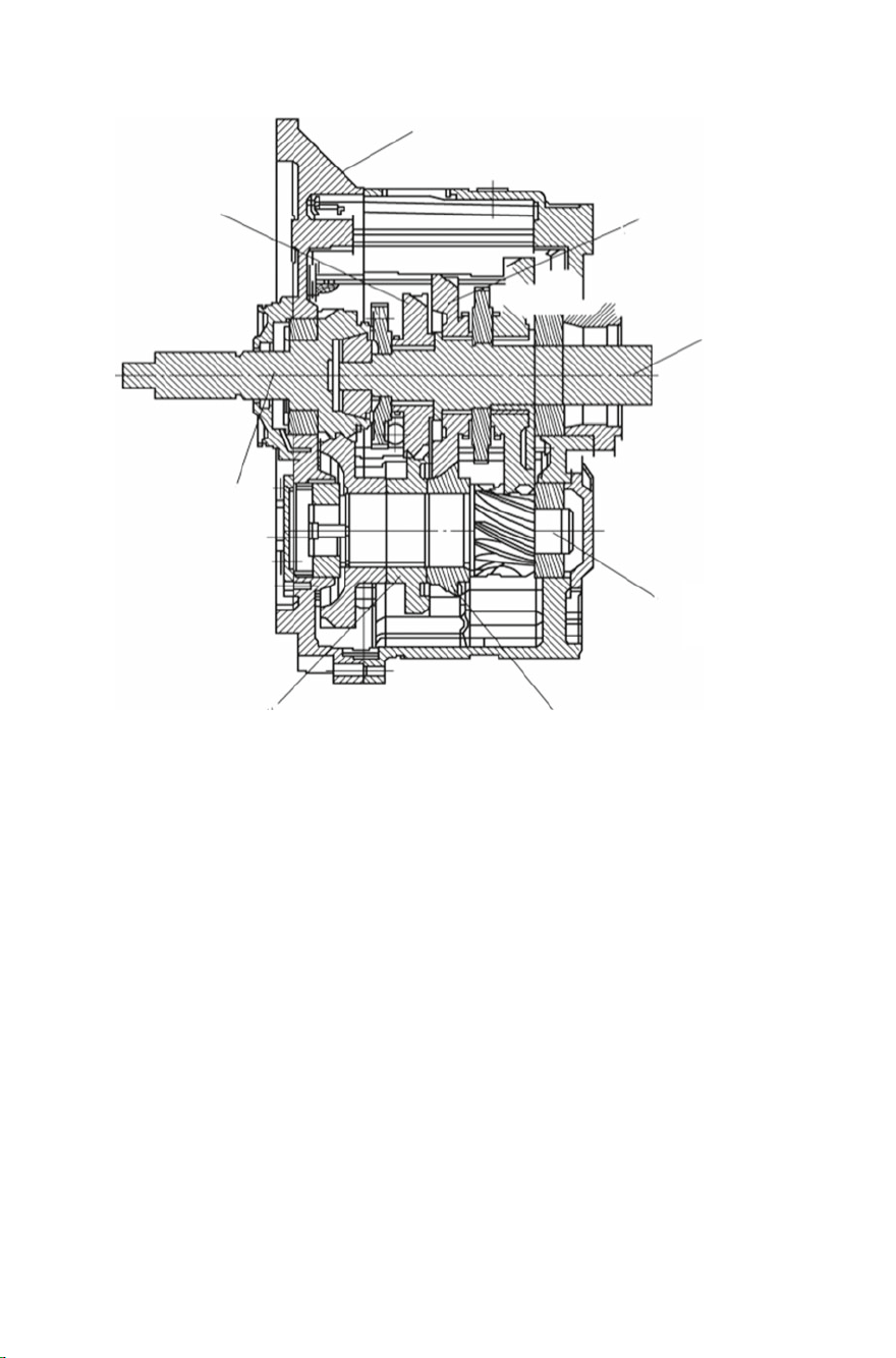
1.3 Basic Structure of Transmission 13
Case
3 speed gear
Input shaft
3 speed gear
Fig. 1.5 Transmission profile
2speed gear
Output shaft
Countershaft
2speed gear
is mainly lubricated by splash lubrication (v>25 m/s, thrown to the wall as long as
the viscosity is appropriate). The transmission profile is shown in Fig. 1.5.
3. Shift control device
In MT, the driver controls the shift, while in AT, the electronic actuating system
completes shift partly or entirely relying on a lot of automation technology. The
neutral, reverse and park are still completed by the driver by controlling the shift
control device. The elements in the shift control device are selected according to the
transmission type and vehicle type. The engaging elements of the transmission for
passenger vehicles mainly include:
(1) Internal engaging elements: shift f ork (Fig. 1.6a), shift synchronizer (Fig. 1.6b),
locking device, multi-disk clutch and brake.
(2) External engaging elements: shift level system, inhaul cable and gear shift lever
Page 26
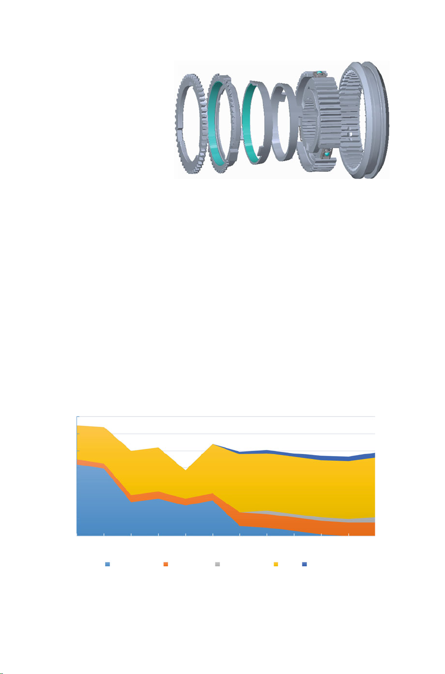
14 1 Introduction
Fig. 1.6 (b) Shift
synchronizer
1.4 Development Status and Trend of Transmission
I. Development status of transmissions
The demand for transmissions varies greatly from region to region. The CVT has
benefited to a certain extent from the continued demand among Japanese users for
small cars that change speeds automatically, making it the best-selling AT type in
Japan. Figure 1.7 shows the demand for transmissions in Japan. The main transmis-
sion enterprises in Japan develop to the high gears (8 and 9) AT. Moreover, the CVT
is developing fast and gradually developing towards high torque.
AT possesses absolute advantage in the US, mainly because the consumers require
simple control and comfortable driving of vehicles but are not sensitive to fuel
consumption, thus forming the AT-dominated AT market in the US. Figure 1.8 shows
the demand for transmissions in the US. The main transmission enterprises in the
US are currently targeting the 6AT. With the continuous development of the wet
clutch technology of BorgWarner, the WDCT will also grow rapidly in the US. The
700
10,000 units
600
500
400
300
200
100
0
2007 2008 2009 2010 2011 2012 2013 2014 2015 2016 2017 2018
3-5 speed AT 6 speed AT 8-9 speed AT CVT DCT&AMT
Fig. 1.7 Demand for transmission in Japan
Year
Page 27
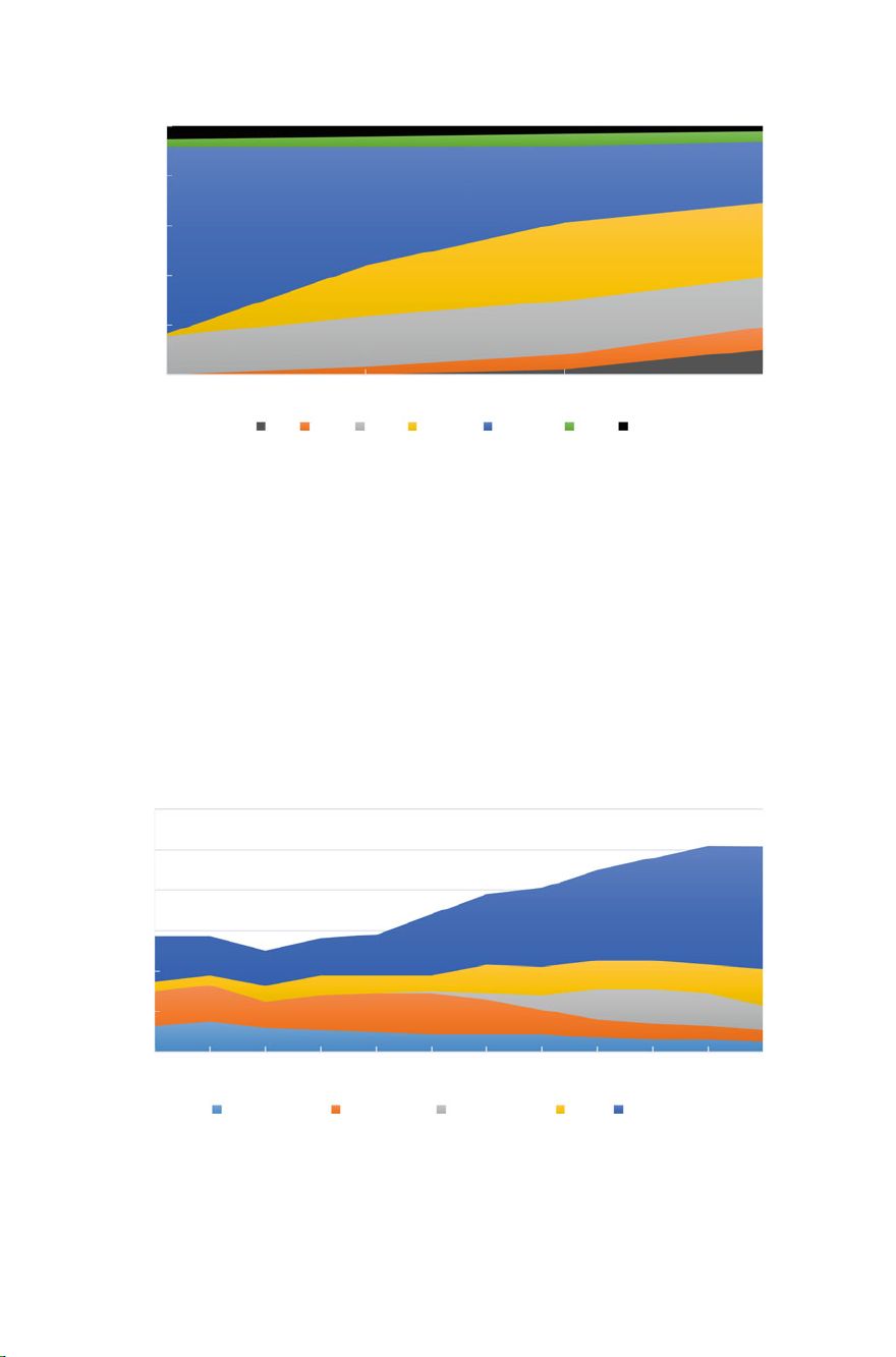
1.4 Development Status and Trend of Transmission 15
100%
80%
60%
40%
20%
0%
2015 2020 2025 2030
EV DHT CVT AT9/10 AT6/7/8 DCT MT
Fig. 1.8 Demand for transmission in the US
Year
higher gear AT produced by the European transmission company is adopted for the
high-grade vehicles.
The European consumers pay attention to driving experience and driving pleasure, like the feeling brought by manual control of the machinery, and think a great
deal of fuel consumption. Therefore, after emergence, the DCT with energy saving
and kinetic characteristics immediately became the darling of the European market.
Figure 1.9 shows the demand for transmissions in Europe. The main transmission
enterprises in Europe have developed towards the high speed (8 and 9) AT and
DCT, and the engineering companies are also pushing the hybrid power technology
vigorously.
600
10,000 units
500
400
300
200
100
0
2007 2008 2009 2010 2011 2012 2013 2014 2015 2016 2017 2018
3-5 speed AT 6 speed AT 8-9 speed AT CVT DCT&AMT
Fig. 1.9 Demand for transmission in Europe
Year
Page 28

16 1 Introduction
10,000 units
AT CVT DCT AMT
Fig. 1.10 Demand for transmission in China
In China, an emerging auto market, the traditional AT was the main choice for
previously automatic transmission vehicles. However, in recent years, the biggest
factors influencing consumers’ decision to buy cars are “price” factors (vehicle
fuel consumption and vehicle price). The number of vehicles assembled with DCT
has increased significantly, and the share of vehicles assembled with CVT has also
increased. Figure 1.10 shows the demand for transmissions in China. Due to accumulated experience in MT development and good process inheritance of AMT and DCT,
the transmission technology develops rapidly in recent years with the involvement
of the engineering companies with outstanding transmission development capability,
and the companies are also trying to make breakthroughs in the AT and CVT fields.
As AT continues to be multi-speed, DCT grows most and the demand for the AT
is increasing year by year. Figure 1.11 shows the demand for AT.
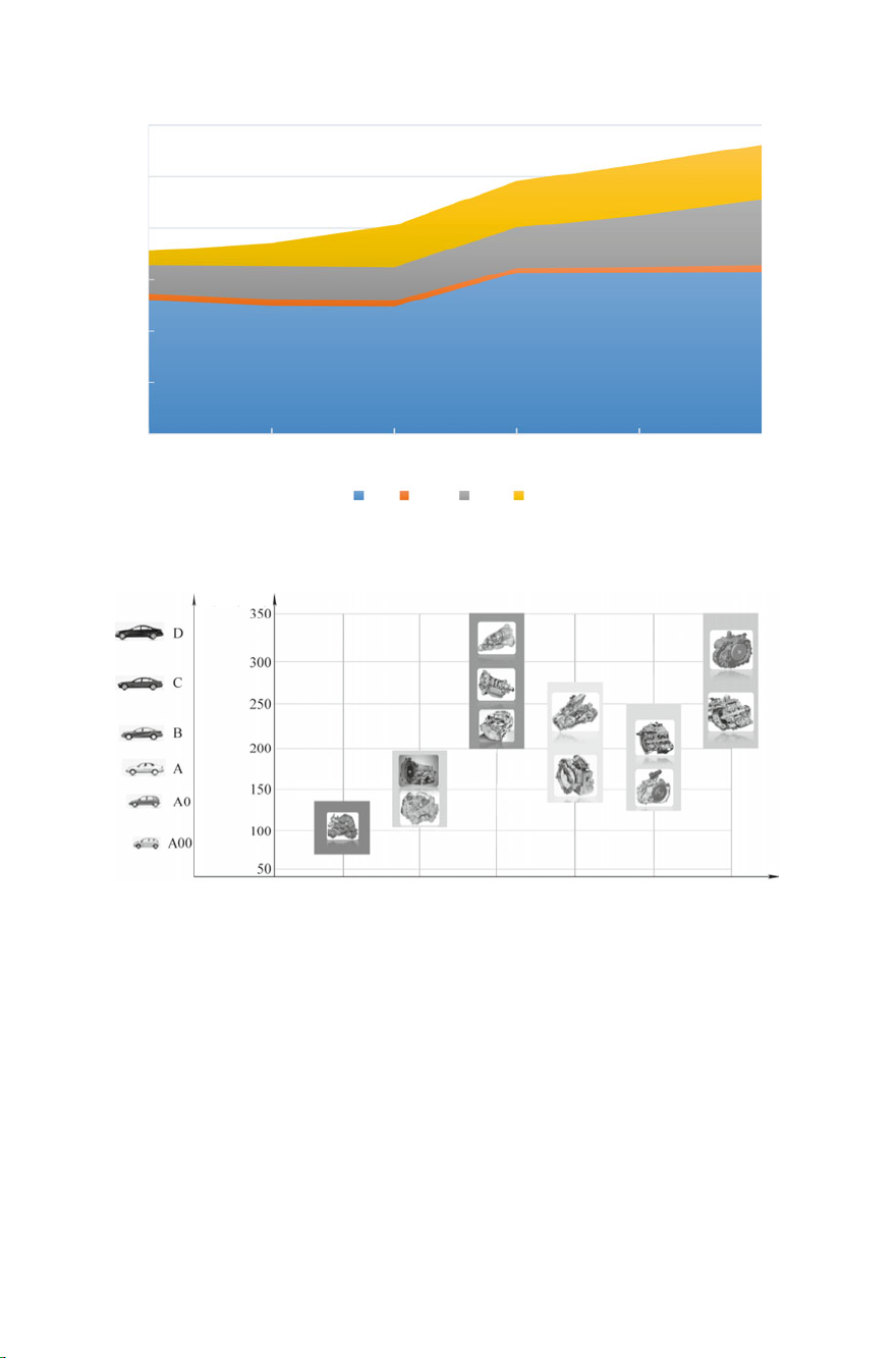
The carrying status of the AT in the passenger vehicles in China is shown in
Fig. 1.12. The 4 speed and 5- speed ATs are mainly assembled in 1.3–1.6 L small
cars and compact cars; the 6-7-8 speed ATs are mainly assembled in the vehicles with
the displacement of 2.0 L and above; the CVT (without hydraulic torque converter) is
mainly assembled in 1.5–1.8 L compact cars; the CVT (hydraulic torque converter)
is mainly assembled in 1.5–2.5 L vehicles; the DDCT is mainly assembled in the
vehicles with the displacement of 2.0 L and below and the WDCT in the vehicles with
the displacement above 2.0 L; the number of applications of turbocharged engine
and DCT combination will increase rapidly.
II. Development trend of transmissions
Energy conservation, environmental protection, safety and high efficiency is the
theme of the development of automotive transmissions, with the pursuit of comfort,
economy and safety from the perspective of consumers and the pursuit of high efficiency, low carbon and environmental protection from the perspective of regulations.
Thus, the transmission companies are required to apply advanced and efficient design,
manufacturing and control technologies and advanced materials to achieve wide gear
Page 29
1.4 Development Status and Trend of Transmission 17
60
Million units
50
40
30
20
10
0
2013 2015 2017 2018 2019 2020
AT AMT CVT DCT
Fig. 1.11 Demand for AT
Torque /(N.m)
Year
5-6 speed AMT 4-5 speed AT 6~8 speed AT CVT DDCT WDCT
Fig. 1.12 Carrying status of the AT in the passenger vehicles in China
ratio and multi-speed of transmission, optimization of the shift strategy,improvement
of the transmission efficiency and light weight of transmissions.
1. Development trend of MT
(1) Multi-speed and large gear ratio of transmission: the three-axis 6 speed
transmission was gradually replacing the dual-axis 5 speed transmission
under thedominance of some European, American and Japanese companies
from twoor three years ago. The 7speed MT supplied by ZF for Porsche 911
Carrera and Carrera S was used in the passenger vehicles for the first time.
Page 30

18 1 Introduction
With increased low speed gear ratio and more reasonable gear, it achieves
the comprehensive optimization of dynamic and economy performance.
(2) High efficiency and reduced NVH: the following measures can be taken
to improve the transmission efficiency: multi-speed transmission; reduce
the immersion height of the differential mechanism in the lubricating oil
and change the lubricating mode from traditional gear splash lubrication
to combination of gear splash lubrication and oil guide lubrication, so as to
reduce the churning loss of the lubricating oil; replace the traditional conical
bearing with ball bearing and roller bearing to reduce the bearing friction
loss; use efficient transmission lubricating oil. To meet the requirement
of noise reduction, the best match of the clutch and transmission shaft
with the transmission shall be considered in addition to the corresponding
measures taken for the transmission, such as precise control of the backlash
in circular tooth of the transmission matching gear, selection of appropriate
gear material, application of low noise bearing and full consideration to the
impact of the gear engagement on the transmission structure in the design
phase.
(3) Light weight and low cost: the light weight and low cost can be achieved
by use of advanced forming technology, reasonable plastics and other nonmetallic materials. The lightweight design of the transmission case based
on CAE can shorten the development cycle, reduce the development cost
and improve the product competitiveness.
(4) Further reduce the space occupied by the transmission and optimize the
space and size of all parts. Due to the application of the start-stop system,
a highly integrated solution with low cost and high reliability that can
identify the neutral and reverse is applied through the detection of reliable
neutral position signals.
2. Development trend of AT
(1) Development trend of hydraulic torque converter: flattened hydraulic torque
converter, increasing torque ratio, extended locking range and sliding friction
range and improved hydraulic torque converter range. With the application of
the engine supercharging technique, the engine torque is increasing and higher
requirements are put forward for the vibration reduction of the transmissions.
The torque converter with centrifugal pendulum vibration absorber and the
torque converter with turbine vibration absorber are presented, significantly
improving the vibration damping performance of the torque converter. The
hydraulic part is optimized to improve the hydraulic torque converter capacity
and optimize the axial space.
(2) Multi-speed AT. The 6~9 speed AT is gradually replacing the 4 or 5 speed trans-
mission. With the increased gears, the transmission may have a larger gear ratio
range and a reasonable gear ratio distribution. ZF has successfully developed
9AT and some companies are already working on 10AT.
(3) AT modular design. The modular design is very obvious in AT, including modu-
larization of hydraulic torque converter, modularization of hydraulic valve body,
Page 31

1.4 Development Status and Trend of Transmission 19
modularization of clutch, modularization of brake, etc. According to different
user requirements, various schemes can be realized through different module
combinations, reducing the design changes, shortening the development cycle
and improving the product competitiveness.
(4) Application of multiple solenoid valves. Multiple solenoid valves are adopted
to control the shift, which can significantly improve the shift quality. To control
the system pressure and achieve shift, six PWM solenoid valves with high flow
capacity are set in the 6AT of ZF, simplifying the valve body structure and
improving the comprehensive performance of the transmission. The transmission efficiency can be further improved if the leakage-free solenoid valve or the
near-leakage-free solenoid valve is used.
(5) Component integration to reduce the mass. For example, the ZF6H26 employs
a gear called Lepetler, which reduces the mass of the gear train by 11 kg; in
A750E/A750F of Toyota, 3 clutches are integrated into the same clutch hub;
the dog clutch used for ZF9HP is longer but smaller than the ordinary clutch
and looks like a spline; some transmission companies use magnesium alloy
transmissions, further reducing the weight of the transmission.
(6) Use of new materials and new processes: the application of new lightweight and
high-strength materials and the application of the stamping forming technology
make great contributions to reducing cost and weight.
3. Development trend of CVT
(1) Improve the CVT efficiency
(1) Reduce the cone disk pressing loss. The applied pressing force and the
adjustment and pressing force are optimized by using a torque sensor
to effectively reduce the flow of the hydraulic system in the adjustment
process, so that a smaller hydraulic pump can be used, which not only
reduces the fuel consumption of the pump, but also reduces the related
energy loss.
(2) Reduce the chain loss. The connecting piece and oscillation pin are used,
characterized by high efficiency, small size, reliable work and low noise.
(3) Reduce the hydraulic pump loss and use the low-energy electric hydraulic
pump.
(4) Reduce the CVT bearing loss and replace the hydraulic torque converter
with the clutch.
(2) Reduce the CVT cost. With respect to the processing technology, the cone disk
group stamped by the steel plates can be used as the main part to reduce the
cost and weight and the shaft machined by cold extrusion can also be used to
reduce the cost; according to different market requirements, the dry clutch or
wet clutch can be used instead of the hydraulic torque converter to reduce the
cost; the CVT case may be optimized to reduce the weight and cost.
(3) Comprehensive optimization of the engine and CVT precise control. The torque
sensor has been widely used, especially for small batch supercharged engines,
to optimize the pressing force and achieve precise control of CVT; it can be
Page 32

20 1 Introduction
integrated with the engine for integrated control to further reduce the fuel
consumption and emission.
(4) Increase the drive torque. Increasing CVT transfer torque has been the focus
of research and development. The new structure of CVT drivetrain, such as
the steel belt designed by BOSCH using new flexible ring materials, with better
dynamic performance, lower cost, higher efficiency and smaller center distance,
can transfer higher torque. The modular design can meet the special customer
requirements in the rapidly developing market, shorten the R&D cycle, and
improve the market competitiveness. The CVT is one of the coupling mechanisms between the HEV engine and the drive motor. An HEV with a CVT
drivetrain can reduce the fuel consumption by 30% and emissions by 50%.
4. Development trend of DCT
(1) Wide gear ratio, multi-speed and light weight: achieve the wide gear ratio,
multi-speed and light weight on the premise of ensuring transmission efficiency.
(2) Modular design: e.g. electro-hydraulic actuator of the motor-controlled DCT,
gear selecting and shifting actuator and wet dual clutch.
(3) Integrated control: the DCT control is combined with engine, ABS, ESP, EPS
and ACC control to realize the integrated control of the powertrain, improve the
performance of the powertrain and optimize the control effect.
(4) Hybrid powertrain: the DCT is combined with the motor/generator to form the
hybrid powertrain, enabling separate engine drive, separate motor drive, and
combined engine and motor drive. When braking, the motor/generator is in the
generating state, and the kinetic energy of the vehicle is converted into electric
energy and stored. This scheme provides the HEV with a dynamic coupling
device that is easy to implement.
(5) Integration and intelligence: all functions of the transmission are integrated into
one unit to reduce the fault sources and improve reliability. In terms of control
strategy, adaptive control, fuzzy control and other intelligent control methods
are adopted to improve the adaptive ability of DCT.
5. Development trend of AMT
(1) Powertrain integration: the AMT control is combined with engine, ABS, ESP,
EPS and ACC control through integrated control to realize the integrated control
of the powertrain, improve the performance of the powertrain and optimize the
control effect.
(2) Use of new structure: for example, ZEROSHIFT has developed a new AMT
technology that uses a series of sliding claws and tooth sockets to allow both
gears to engage at the same time when shifting gears. It has all the advantages
of a dual clutch, with a simple design and low cost.
(3) Hybrid powertrain: the AMT is combined with the wheel-side motor/generator
to form the hybrid powertrain, enabling separate engine drive, separate motor
drive, and combined engine and motor drive. During the shift, the motor drives
the vehicle to improve the dynamic performance of the vehicle; when braking,
the motor/generator is in the generating state, and the kinetic energy of the
Page 33

1.4 Development Status and Trend of Transmission 21
vehicle is converted into electric energy and stored. This scheme provides the
HEV with a dynamic coupling device that is easy to implement.
(4) Integration and intelligence: all functions of the transmission are integrated into
one unit to reduce the fault sources and improve reliability; in terms of control
strategy, adaptive control, fuzzy control and other intelligent control methods
are adopted to improve the adaptive ability of AMT.
In conclusion, due to the increasing traffic congestion and the increasing number
of female drivers, more and more users choose automatic transmission for the convenience of driving; the ATtechnology continues to be mature, the quality and efficiency
are improving and the coverage of models is increasing; in recent years and in the next
few years, most of the AT in mass production is DCT, and the output of Chinese and
European models based on DCT will exceed that of Japanese models based on CVT;
6AT has entered the mature stage, and the AT with more gears will be mainly applied
to high-end models. The overall market share of AT is flat or slightly decreased; the
market share of the AMT will increase slightly due to fuel consumption and cost. The
self-owned brand AT is increased mainly due to the decrease of DCT and MT, but
the reduction rate will not be too fast due to the limitation of consumers’ purchasing
power. The substantial incentives taken by the government in taxation, subsidies and
other aspects are the main reason for the rapid growth of the NEV market. In order
to meet the fuel consumption standard of 5 L/100 km in 2020, enterprises need to
vigorously develop new energy vehicles.
Bibliography
1. Yong Chen (2008) New development and trend of automatic transmission technologies.
Automot Eng 30(10):938–945
2. Ge A (2001) Automatic transmission (I)—overview of automatic transmission. Automob
Technol (5):1.3
3. Guangqiang Wu, Weibin Yang, Datong Qin (2007) Key technique of dual clutch transmission
control system. Chin J Mech Eng 43(2):13–21
4. Li J, Zhang J, Feng J, et al (2000) Development, current situation and forecast of automated
mechanical transmission. Automob Technol (3):1.3
5. Mingkui Niu, Xiusheng Cheng, Bingzhao Gao et al (2004) A study on shifting characteristics
of dual clutch transmission. Automot Eng 26(4):453–457
6. Yang W, Wu G, Qin D (2007) Drive line system modeling and shift characteristic of dual clutch
transmission powertrain. Chin J Mech Eng 43(7):188–194
7. Niu M, Gao B, Ge A, et al (2004) Dual-clutch type automatic transmission system. Automob
Technol (6):1.3
8. Guo L, Ge A, Zhang T et al (2003) AMT shift process control. Trans Chin Soc Agri Mach
34(2):1.3
9. Yongjun Li, Shuxin Chen, Yong Cui et al (2003) Integrated control of the starting process of
automated mechanical transmission. Automot Eng 25(2):178–181
10. Ge A (2001) Automatic transmission (II)—hydraulic torque converter. Automob Technol
(6):1.5
11. Cao G, Ge A, Zheng L, et al (2005) Clutch engagement control during gear shifting process in
automated manual transmission. Chin J Mech Eng 41(12):234–238
Page 34

22 1 Introduction
13. Lei Y, Yi Y, Ge A (2001) Integrated and intelligent shifting control of automated mechanical
transmission. Automot Eng 23(5):311.314
14. Lun Jin, Xiusheng Cheng, Li Sun et al (2005) Simulation and studies on dual-clutch automatic
transmission. Automob Technol 8:4–7
15. Liao C, Zhang J, Lu Q (2005) Coordinated powertrain control method for shifting process of
automated mechanical transmission in the hybrid electric vehicle. Chin J Mech Eng 41(12):37–
41
16. Qin D, Liu Y, Hu J, et al (2010) Control and simulation of launch with two clutches for dual
clutch transmissions. Chin J Mech Eng 46(18):121.127
17. Yong C, Wenjiang Z, Wenzhong L (2009) Present situation and future trends of automatic
transmission in China. SAE-China Congr Proc
18. BingZhou, Qinghua Jiang, YiYang (2011) Transmissionratio optimization with dual objectives
of power performance and economy for a two-speed electric vehicle. Automot Eng 33(9):792–
797
19. Xiaoming Weng (2009) A study on the shift quality of wet double clutch transmission. Automot
Eng 31(10):927–931
20. Justin K, Anne-Catrin U, Lowy FD (2015) Staphylococcus aureus infections: transmission
within households and the community. Trends Microbiol 23(7):437–44
21. Haydon PG, Giorgio C (2006) Astrocyte control of synaptic transmission and neurovascular
coupling. Physiol Rev 86(3):1009–1031
22. Oh HR, Song H (2012) Energy efficient MAC protocol for delay-sensitive data transmission
over wireless sensor network. Wireless Commun Mob Comput 12(9):755–766
23. Kumnuan U, Prasert A, Dowell SF, et al (2005) Probable person-to-person transmission of
avian influenza A (H5N1). New England J Med 352(4):333–340
24. Clayton D (2010) A generalization of the transmission disequilibrium test for uncertain
haplotype transmission. Am J Hum Genet 65(4):1170–1177
25. Jackson JB, Musoke P, Fleming T et al (2003) Intrapartum and neonatal single-dose nevirapine
compared with zidovudine for preventionof mother-to-child transmission of HIV-1 in kampala,
uganda: 18-month follow-up of the HIVNET 012 randomised trial. Lancet 362(9387):859–868
26. Seto WH, Tsang D, Yung RWH, et al (2003) Effectiveness of precautions against droplets
and contact in prevention of nosocomial transmission of severe acute respiratory syndrome
(SARS). Lancet 361(9368):1519–1520
27. Han SH, Lee JH (2005) An overview of peak-to-average power ratio reduction techniques for
multicarrier transmission. IEEE Wirel Commun 12(2):56–65
Page 35

Chapter 2
Manual Transmission
2.1 Overview
Despite the rapid development of automatic transmission technology, the traditional
engine-matched manual transmission (MT) will continue to play an important role
for some time to come, mainly because of its low cost, high efficiency and reliable
operation. At present, 5 speed MT is mainly used in China, and some cars start to
carry 6 speed MT, covering SUV, middle-sized and compact vehicles. The 6 speed
MT will gradually become the mainstream. ZF and BMW are developing the 7 speed
MT.
By the engine and drive shaft connection mode, the MT may be classified into
FF layout, FR layout and RR layout; by the form and arrangement form of the shaft,
the MT can be classified into two-shaft and three-shaft MT; by the gear type, the
MT can be classified into spur gear and helical gear types; by the synchronizer type,
the MT can be classified into constant pressure, inertial and inertial boost types and
the most widely used type currently is the inertial synchronizer of the structures
including slide, lock pin, lock ring and multi-cone types; by the number of gears,
the MT can usually be classified into 5, 6 and 7 speed transmissions. The FF layout
is mostly used for the cars. With the multi-speed development and restricted by the
spatial and axial dimensions of the transmissions, the three-shaft 6 speed or 7 speed
transmission will gradually become the mainstream transmission.
2.2 Transmission Drive Mechanism
An MT mainly consists of the powertrain, shift system, lubrication system and case.
The powertrain consists of the input shaft, output shaft, gears, bearing, synchronizer
and differential mechanism; the shift system consists of the shift fork, gear shifter
shaft, self-lock device and interlock device. Figure 2.1 is the structural diagram of
MT. The transmission has 6 forward gears and 1 reverse gear (R gear) and is of
© China Machine Press and Springer Nature Singapore Pte Ltd. 2021
Y. C h e n, Automotive Transmissions, Springer Tracts in Mechanical Engineering,
https://doi.org/10.1007/978-981- 15-6703-2_2
23
Page 36

24 2 Manual Transmission
Shift system
Case and lubrication system
Fig. 2.1 Structural diagram of MT
Powertrain
Case and lubrication system
3-parallel shaft structure (1 input shaft and 2 output shafts). It has been widely used
in the FF passenger vehicles because of its small axial distance and easy spatial
arrangement. Figure 2.2 shows the MT drive diagram, where, g1–g17 are gears and
S1–S4 are synchronizers. The drive lines of all gears are as follows:
1 speed drive line: clutch C → input shaft → gear g2 → gear g9 → left shift
of synchronizer S1 → output shaft 1 → gear g7 → gear g17 → differential
mechanism → wheel.
2 speed drive line: clutch C → input shaft → gear g3 → gear g10 → right shift
of synchronizer S1 → output shaft 1 → gear g7 → gear g17 → differential
mechanism → wheel.
3 speed drive line: clutch C → input shaft → gear g5 → gear g12 → right shift
of synchronizer S2 → output shaft 1 → gear g7 → gear g17 → differential
mechanism → wheel.
4 speed drive line: clutch C → input shaft → gear g4 → gear g11 → left shift
of synchronizer S2 → output shaft 1 → gear g7 → gear g17 → differential
mechanism → wheel.
5 speed drive line: clutch C → input shaft → gear g4 g4 → gear g15 → left
shift of synchronizer S3 →
output shaft → gear g13 → gear g17 → differential
mechanism → wheel.
6 speed drive line: clutch C → input shaft → gear g6 → gear g16 → right shift
of synchronizer S3 → output shaft 2 → gear g13 → gear g17 → differential
mechanism → wheel.
Page 37

2.2 Transmission Drive Mechanism 25
Fig. 2.2 MT drive diagram
Input shaft 1
Input shaft
Input shaft2
R speed drive line: clutch C → input shaft → gear g1 → gear g8 → gear g14
→ left shift of synchronizer S4 → output shaft 2 → gear g13 → gear g17 →
differential mechanism → wheel.
Based on the above analysis, the gear ratios of all gears are shown in Table 2.1.
The number of teeth of each gear is represented by Z
, and the subscript i corresponds
i
to the gear label in Fig. 2.2. In reverse gear, the input shaft rotates in the opposite
direction to the output gear of the main reducer; in other gears, the input shaft rotates
in the same direction as the output gear of the main reducer.
Table 2.1 Gear ratio of each gear
Gear K 1 2 3 4 5 6 R
Gear ratio i
Z9×Z
gk
Z2×Z
Z10×Z
17
Z3×Z
7
Z12×Z
17
Z5×Z
7
Z11×Z
17
Z4×Z
7
Z15×Z
17
Z4×Z
7
Z16×Z
17
Z6×Z
13
Z14×Z
17
13
Z1×Z
17
13
Page 38

26 2 Manual Transmission
2.3 Synchronizer
As an important part of MT, the synchronizer has a very important impact on the
main technical indicators of the transmission such as shift portability and smoothness,
can reduce the shift force on the shift knob, and reduce the shift impact and driver
fatigue. An ideal synchronizer should have good synchronization performance and
locking performance, which can not only achieve the shortest synchronization time
with small shift force, but also ensure that the synchronizer clutch and lock ring will
not enter the joint when the angular velocity is not consistent at the input and output
ends.
At present, all synchronizers adopt the principle of friction, that is, the friction
moment is generated on the working surface to overcome the inertia moment of the
meshed part, so as to reach the synchronization status in a short time and change
gears easily.
I. Structure and characteristics of synchronizer
There are constant pressure, inertial and inertial boost synchronizers, of which, the
inertial synchronizer is most widely used. The lock ring type inertial synchronizer
is mainly used for the passenger cars and light trucks, as shown in Fig. 2.3, and
mainly consists of the mating spline, synchronous ring, synchronizer splined hub,
synchronizer clutch, locking slider and spring.
The mating spline and the drive gear are combined into one. When the gear is
engaged, the mating spline meshes with the spline inside the synchronizer clutch to
drive the driving moment. The cone angle of its external conical surface is equal to
that of the synchronous ring. When the gear is engaged, the external conical surface
and the synchronous ring generate a synchronous friction moment.
The synchronous ring is a conical ring with grooves on the internal conical surface
that can destroy the oil slick and rapidly discharge the lubricating oil. These grooves
can be radial or circumferential. On the external conical surface, there are usually
uniformly distributed notches equal to the number of sliders to hold and push the
locking slider; in addition, there are short lock teeth and the included angle between
the bevels of the lock teeth is the lock angle. When the mating spline synchronizes
with the synchronizer hub, these bevels allow the synchronizer clutch to slip in with
a slight rotation.
The synchronizer splined hub is connected to the shaft through the spline on the
inner diameter, and the spline is also processed on the outer diameter. The spline
is connected to the synchronizer clutch, and the loading lock sliders are evenly and
uniformly distributed on the outer side of the synchronizer hub.
The splines connected to the synchronizer hub are processed on the inner ring
of the synchronizer clutch; large circumferential grooves are processed on the outer
ring to place the shift fork. The whole gearshift operates the shift fork axially and
then acts on the synchronizer clutch.
The locking slider and spring constitute a central locking and positioning mech-
anism. Usually, there are three or four pairs of locking and positioning mechanisms
Page 39

2.3 Synchronizer 27
Fig. 2.3 Lock ring type
inertial synchronizer. 1,
8—mating spline, 2,
7—synchronizer splined
hub, 4—synchronizer clutch,
5—locking slider, 6—spring
evenly distributed, whose function is to keep the synchronizer clutch in the middle of
the synchronizer hub between two gears in the neutral position and keep the synchronizer clutch in the neutral position under the action of certain axial force. When the
axial force does not reach a given value, the synchronizer clutch is prevented from
sliding axially in relation to the synchronizer hub.
II. Shift process of synchronizer
The shift process of the synchronizer is mainly divided into the following 6 stages,
and the states of each stage are shown in Fig. 2.4.
Stage 1: the synchronizer clutch is not meshed with the mating spline and is in the
neutral position, as shown in Fig. 2.4a. At this point, even if the clutch is engaged,
the transmission cannot drive the torque, the wheel cannot rotate and the vehicle
remains stationary. The locking slider is pressed on the inner circumference of
the synchronizer clutch under the action of the spring force and the bump on
the surface of the locking slider inhibits the axial movement of the synchronizer
Page 40

28 2 Manual Transmission
(a) Stage 1: neutral position (b) Stage 2: locking slider and synchronizer
(c) Stage 3: synchronizer action and speed
synchronization
clutch action
(d) Stage 4: synchronizer staggering after
synchronization
(e) Stage 5: synchronizer clutch in contact with
mating spline
(f) Stage 6: synchronizer clutch and mating
spline are engaged
Fig. 2.4 State of each stage in the synchronizer shift process
Page 41

2.3 Synchronizer 29
clutch. The synchronizer clutch remains in its natural state under the external
force within a certain limit.
Stage 2: The driver manipulates the gear shift lever towards the selected gear, the
action of the shift fork is transferred to the synchronizer clutch, and the synchronizer clutch and locking slider act, as shown in Fig. 2.4b. When moving towards
the selected gear, the locking slider is pressed on the side of the synchronous ring.
Under this force, the synchronous ring is in contact with the integrated cone of the
mating spline. Because of the speed difference between the synchronous ring and
the mating spline, the synchronous ring can only rotate within the range allowed
by the locking slider mounting groove, and the lock chamfer on the end face of the
synchronizer clutch and that of the synchronous ring turn to opposite positions.
This state is called the flag state of synchronization.
Stage 3: The locking slider stops here, the synchronizer clutch further moves
towards the mating spline and the lock chamfer on the end face of the synchronizer
clutch is in contact with that of the synchronous ring, as shown in Fig. 2.4c.
At this time, the synchronous ring presses on the conical surface of the mating
spline, producing the friction moment. The driving moment of the input shaft
→ synchronizer splined hub → synchronizer clutch is transferred to the mating
spline and the speed starts to synchronize. In order to ensure reliable contact and
smooth shift, there are many tricks for the shape selection of lock chamfer on the
end face of the synchronizer clutch and that of the synchronous ring, which are
the key of MT design.
Stage 4: the synchronizer clutch is fully synchronous with the mating spline, as
shown in Fig. 2.4d. The friction moment between the synchronous ring and the
conical surface of the mating spline gradually disappears. In this state, the synchronizer clutch continues to move towards the mating spline. While the contact
surface between the chamfer of the spline on the end face of the synchronizer
clutch and the chamfer of the synchronous ring slides, the synchronizer clutch
moves towards the meshing direction with the mating spline and enters the socalled turning stroke (stagger). The moment generated by the synchronizer clutch
chamfer and synchronous ring chamfer in the turning process affects the shift feel.
It is one of the MT design parameters and the key of MT design.
Stage 5: the synchronizer clutch continues to move towards the mating spline, and
the spline chamfer of the synchronizer clutch comes in contact with the mating
spline, as shown in Fig. 2.4e. During the shift, the control force of the gear shift
lever is small and the synchronizer clutch has been fully synchronous with the
mating spline. In order to prevent noise and ensure relatively smooth engagement,
it is still critical to design the chamfer shape.
Stage 6: the synchronizer clutch continues to move towards the mating spline, the
synchronizer clutch is fully engaged with the mating spline and the shift finishes,
asshowninFig.2.4f. The driveshaft → synchronizer splined hub → synchronizer
clutch → synchronous ring are mechanically connected with the mating spline
and are in the integral rotation state. The engine torque and speed are converted
to the corresponding transmission output torque and speed according to the gear
ratio of the selected gear and transmitted to the wheel via the transmission output
Page 42

30 2 Manual Transmission
shaft and then via the differential mechanism. In the state of torque drive, the
contact surface between the synchronizer clutch and mating spline needs to bear
a large drive torque, which shall be easy to mesh and cannot be out of gear.
III. Working principle of synchronizer and determination of main parameters
1. Working principle of synchronizer
The gear shall be disengaged before shift, so that the transmission is in neutral
position. The output end of the transmission is connected to the vehicle and has a
considerable rotational inertia, so the speed at the output end of the synchronizer
connected to the output end of the transmission is constant at the moment of shift,
while the speed at the input end of the synchronizer is different from that at the output
end. The speed at the input end of the synchronizer can achieve consistent with that
at the output end through the friction moment of the synchronizer. Assuming that the
churning loss at the input end of the synchronizer and the bearing friction moment are
ignored, the following moment equation can be obtained by using the synchronizer
diagram shown in Fig. 2.5:
dω
= J
T
m
i
i
dt
(2.1)
where: T
—friction moment of synchronizer;
m
—rotational inertia at the input end of the synchronizer;
J
i
—rotational angular velocity at the input end of the synchronizer;
ω
i
t—time.
The axial force acting on the synchronizer through the gear shift lever has the
following relationship with the friction moment of the synchronizer
FμR
=
T
m
sin α
Fig. 2.5 Synchronizer
diagram
(2.2)
Page 43

2.3 Synchronizer 31
Fig. 2.6 Force analysis of
locking surface
Synchronous ring
Synchronous gear sleeve
where: F—axial force acting on the synchronizer;
μ—friction factor between working faces;
R—mean radius of conical surface;
α—cone angle.
Assuming that the difference between the rotational angular velocities at the input
and output ends of the synchronizer is ω and the velocity is synchronous at the
time t, the friction moment equation at the time of synchronization is
= J
i
ω
t
(2.3)
FμR
sin α
At the synchronizer action shown in Fig. 2.4c, i.e. the speed synchronization stage,
the lock chamfer on the end face of the s ynchronizer clutch is in contact with that of
the synchronous ring. The force analysis of the locking surface is shown in Fig. 2.6
and the axial force F and tangential force F
are as follows:
z
F = Nsinβ + μ
cos β (2.4)
s
where: N—positive pressure acting on the locking surface;
β—lock angle;
—static friction factor between the locking surfaces.
μ
S
= N(cos β − μssin β
where: F
F
z
—tangential force acting on the synchronous ring.
Z
)
From formulas (2.4) and (2.5)
sin β)
s
The tangential force F
Z
a ring toggle moment M
F(cos β − μ
F
=
z
sin β + μscos β
acting on the synchronous ring forms
T
(2.5)
(2.6)
Page 44

32 2 Manual Transmission
where: R
MT= FzR
—pitch radius of synchronous ring lock chamfer.
S
s
To ensure synchronization before shift, the locking condition of T
m
(2.7)
≥ MTmust
be met, i.e.
= 0, formula (2.8)is
If μ
S
μR
sin β
(sin β − μscos β)
R
s
≥
cos β + μssin β
μR
Rssin β
≥ tan β (2.9)
(2.8)
The formula (2.9) is used to determine the lock angle required for locking. Foreasy
shift of cars, β = 105°–125°, so that a larger ring toggle moment can be generated.
2. Calculation of rotational inertia
The rotational inertia at the input end of each gear of synchronizer shall be calculated
during the shift. Taking the MT drive diagram in Fig. 2.2 for example, this part of
rotational inertia includes the rotational inertia of the input shaft and its connecting
gear, the rotational inertia of the clutch driven plate and the rotational inertia of the
constant mesh gear in the input shaft gears.
The basic relation of the rotational inertia conversion is as follows
2
Z
J
= J
Z
Z
B
Z
B
(2.10)
where: J
—rotational inertia after conversion;
Z
—converted rotational inertia;
J
B
—number of teeth in the converting shaft;
Z
Z
—number of teeth in the converted shaft.
Z
B
The rotational inertia converted to the input shaft in the neutral position is
= JL+ Jsr+ J1+ J2+ J3+ J4+ J5+ J
J
rk
where: J
—rotational inertia of the clutch driven plate;
L
—rotational inertia of the input shaft and its connecting gear;
J
sr
—rotational inertia converted by the gears g8 and g14 to the input shaft;
J
1
—rotational inertia converted by the gear g9 to the input shaft;
J
2
—rotational inertia converted by the gear g10 to the input shaft;
J
3
6
J4—rotational inertia converted by the gears g11 and g15 to the input shaft.
—rotational inertia converted by the gear g12 to the input shaft;
J
5
—rotational inertia converted by the gear g16 to the input shaft.
J
6
(2.11)
Page 45

2.3 Synchronizer 33
J1= J
J
= J
4
g11
2
Z
1
g8
Z
8
J
= J
2
g9
J
= J
3
g10
Z
4
Z
11
J
= J
5
g12
J
= J
6
g16
+ J
2
Z
Z
Z
Z
+ J
Z
Z
Z
Z
2
9
10
12
16
g14
3
5
6
g15
2
Z
1
Z
14
2
(2.12)
(2.13)
2
(2.14)
2
Z
4
Z
15
2
(2.15)
(2.16)
2
(2.17)
where: J
—rotational inertia of gear g8;
g8
—rotational inertia of gear g9;
J
g9
—rotational inertia of gear g10;
J
g10
—rotational inertia of gear g11;
J
g11
—rotational inertia of gear g12;
J
g12
—rotational inertia of gear g14;
J
g14
—rotational inertia of gear g15;
J
g15
—rotational inertia of gear g16.
J
g16
See Table 2.2 for the rotational inertia at the input end of the synchronizer at each
gear.
3. Calculation of angular velocity difference
The angular velocity of the parts at the input end of the synchronizer changes before
and after the shift, while the vehicle speed may be deemed unchanged before and after
shift. Therefore, the angular velocity of the parts at the input end of the synchronizer
before and after shift can be calculated by the speed. Combined with Fig. 2.2, when
the vehicle speed is v (m/s) and the wheel radius is r (m), taking the conversion of
gear 3 to another gear for example, the angular velocity difference of the parts at the
input end of the synchronizer before and after shift is analyzed, as shown in Table 2.3.
Table 2.2 Rotational inertia at the input end of the synchronizer
Gear 1 2 3 4 5 6 R
Rotational inertia at the input
end(× J
)
rk
Z
9
Z
2
2
Z
Z
10
3
2
Z
Z
12
5
2
Z
Z
2
11
4
Z
Z
15
4
2
Z
Z
16
6
2
Z
14
Z
1
2
Page 46

34 2 Manual Transmission
Table 2.3 Angular velocity difference of the parts at the input end of the synchronizer before and
after shift
Gear k 1 2 3 4 5 6
(a) Angular velocity of the parts at the
input end of the synchronizer before
shift×
Vi
g3
r
(b) Angular velocity of the parts at the
input end of the synchronizer after shift
Vi
g3
×
r
(c) Angular velocity difference of the parts
at the input end of the synchronizer
before and after shift×
Vi
g3
r
(d) Angular velocity rise and fall at the
Z
Z
Z
Z
2
Z
9
Z
Z
5
Z
12
(a)–(b) (a)–(b) (a)–(b) (a)–(b) (a)–(b) (a)–(b)
Rise Rise – Fall Fall Fall
Z
Z
3
5
Z
10
5
12
Z
12
Z
5
Z
Z
12
Z
4
Z
11
Z
Z
5
Z
12
Z
4
6
Z
16
15
Z
5
5
Z
12
12
input end of the synchronizer
4. Maximum line velocity of synchronous ring
The friction line velocity u of the synchronous ring plays an important role in the
thermal stress. The friction surface temperature increases exponentially with the
increase of the line velocity and the maximum line velocity under the maximum
angular velocity difference ω
max
is
= R
ω
s
max
of the synchronous ring at each
V
measured at the input shaft when
Vi
u
max
5. Resistance moment T
of synchronous ring
v
It is difficult to calculate the resistance moment T
gear. Table 2.4 shows the resistance moment T
the fuel temperature is 80 °C and their relationship is
where: i
—gear ratio from the input shaft to the synchronizer;
g
—fuel temperature correction factor, taken 1 at the room temperature. The factor
will be greater than 1 with the decrease of the temperature.
Table 2.4 Resistance moment T
Empirical value Passenger vehicle Commercial vehicle Vehicle with auxiliary
Resistance moment
T
/(N m)
Vi
2–5 4–8 10–141
measured at the input shaft at the fuel temperature 80 °C
Vi
transmission
(2.18)
(2.19)
Page 47

2.3 Synchronizer 35
6. Synchronous ring friction moment Trconsidering resistance moment T
V
In the synchronization process, the synchronous ring friction moment Trconsidering
resistance moment T
where: t
—synchronization time.
R
In the upshift, ω < 0, the resistance moment T
moment T
have the same direction and work together, favorable for shifting; in the
R
downshift, ω > 0, the resistance moment T
moment T
are in different directions and work together, not favorable for shifting.
R
maybeexpressedas
V
=−J
T
R
ω
− T
rk
t
v
R
and the synchronous ring friction
v
and the synchronous ring friction
v
(2.20)
7. Sliding friction work W
The relationship of the sliding friction work W with ω, T
and tRin the
v
synchronization
1
(J
W =−
In the upshift, ω < 0, the resistance moment T
work W; in the downshift, ω > 0, the resistance moment T
ω2+ TvωtR) (2.21)
rk
2
reduces the sliding friction
v
increases the sliding
v
friction work W.
8. Sliding friction power P
m
W
Pm=
t
R
(2.22)
9. Stress per unit area σ
The synchronous ring contact pressure N is generated under the action of the shift
force F during synchronization. The stress per unit area σ under the contact pressure
Nis
where: A
N
σ =
A
R
—sum of all friction areas of the synchronizer.
R
(2.23)
10. Lock Angle
There is a drag torque between the MT clutch and its drive mechanism. Even if the
input and output of the synchronizer are fully synchronized, the synchronizer clutch
Page 48

36 2 Manual Transmission
Small lock angle
Middle lock angle
Large lock angle
Minimum drag torque
Maximum drag torque
Drag torque/(N.m)
Shift force/N
Fig. 2.7 Relationship between shift force and drag torque T
Z
shall pass through the synchronous ring and overcome the rotational input of the
drag torque under the shift force to fully engage with the soldered teeth. Therefore,
the drag torque T
and the shift force F must satisfy the following relationship
z
(cos β − μssin β)
FR
s
<
T
z
sin β + μscos β
(2.24)
Figure 2.7 shows the relationship between the shift force F and the drag torque
T
. With respect to a lock angle, only when the rotating torque generated by a certain
z
shift force F is greater than the drag torque, can the synchronizer clutch be fully
engaged with the soldered teeth. That is, the gear can be engaged only when the drag
torque is below the curve. With the decrease of the lock angle, the drag torque T
can be overcome increases.
11. Shift force
The actual shift force applied by the driver is largely dependent on the driving style,
temperature and road conditions. When the temperature is low, the transmission drag
torque is high, the shift force is increased and the shift time is longer. Table 2.5 lists
Table 2.5 Standard values of value shift force and synchronization time
Standard value Gear Passenger vehicle Commercial vehicle
Shift force/N Gear 1—top gear 80–120 180–250
Synchronization time/s Gear 1—top gear 0.15–0.25 0.25–0.40
z
Page 49

2.3 Synchronizer 37
Upshift
Downshift
Synchronization time/s
Shift force/N
Small rotational inertia
Large rotational inertia
Synchronization time/s
Synchronization time/s
Shift force/N
Synchronization time/s
Shift force/NShift force/N
Small rotational inertia
Large rotational inertia
Small upshift drag
Large upshift drag
Small downshift drag
Large downshift drag
Fig. 2.8 Relationship between shift force and synchronization time
the acceptable standard values of shift force and synchronization time, and Fig. 2.8
shows the relationship between the shift force and synchronization time.
IV. Main evaluation indicators of synchronizer
(1) Synchronization time: conform to Table 2.5.
(2) Shift force: conform to Table 2.5.
(3) Maximum line velocity of synchronous ring: conform to Table 2.6.
(4) Compressive stress per unit area: conform to Table 2.6.
(5) Sliding friction work: conform to Table 2.6.
Table 2.6 Designed allowable value for the formation of friction pairs between steel and certain
materials
Synchronous
ring
Special brass 0.08–0.12 5 0.09 0.45 3
Mo-sprayed 0.08–0.12 7 0.53 0.84 6
Sintered
material
Friction
factor
Maximum line
velocity/(m/s)
Sliding
friction work
per unit
area/(J/mm
Sliding friction
power per unit
area/(W/mm
2
)
2
)
0.08–0.12 9 1.00 1.50 7
Compressive
stress per unit
area/(N/mm
2
)
Page 50

38 2 Manual Transmission
(6) Sliding friction power: conform to Table 2.6.
(7) Reliability: the synchronizer works reliably under various operating condi-
tions. In particular, it is necessary to ensure reliable shift at low temperature,
prevent forced engagement when the input and output speeds are out of sync,
and prevent spontaneous out-of-gear after full engagement.
(8) Life: generally more than 150,000 km for passenger vehicles and more than
1,200,000 km for commercial vehicles.
(9) Cost: including development costs and manufacturing costs.
(10) Quality and installation space requirements.
2.4 Transmission Operating Mechanism
The transmission operating mechanism shall ensure that the driver can accurately
and reliably engage the transmission into any required gear and can make it back to
neutral at any time. The transmission operating mechanism shall meet the following
requirements:
(1) Only one gear is allowed when shifting, usually by means of the interlock device.
(2) In the shift, the gears shall be engaged on the full length of the teeth and prevented
from automatic spontaneous out-of-gear.
(3) A reverse lock is usually used to prevent accidental engagement of reverse gear.
When the transmission begins to engage the reverse gear, it draws attention of
the driver that obvious hand feel is generated from large resistance as a result
of the role of the reverse lock.
The transmission operating mechanism can be divided into two types: direct and
indirect control. In the direct control transmission operating mechanism, the transmission is arranged in the lower part of the cab and the gear shift lever is extended
from the cab floor besides the driving seat. It is of simple structure and convenient
operation, but it requires the equal stroke of each gear shift. It has been applied
in the FR vehicles. In the indirect control transmission operating mechanism, the
transmission is arranged far away from the driving seat. The operating mechanism
shall have sufficient stiffness and the gap at the connection points shall be small,
otherwise it will affect the feel when shifting gears. Figure 2.9 shows the indirect
control transmission operating mechanism, which mainly consists of the gear shift
lever, cable and select-shift actuator.
I. Gear shift lever
The gear shift lever, as a part of the transmission assembly and a component of
the human-machine interaction device, is to change the gear ratio of the automotive
transmission through the driver’s control to realize the change of the vehicle driving
gear. The gear number and position of MT of various models are not the same, but
the gear arrangement principle is basically the same: the forward gear progressively
Page 51

2.4 Transmission Operating Mechanism 39
Fig. 2.9 Indirect control
transmission operating
mechanism
Cable
Gear shift lever
Cable
Select-shift actuator
increases from top down, first left and then right; the reverse gear is in the upper left
or lower right corner; the neutral is in t he horizontal middle position. Figure 2.10
shows the gear arrangement of the commonly used hand shift lever.
Fig. 2.10 Gear arrangement
of the commonly used hand
shift lever
Page 52

40 2 Manual Transmission
Table 2.7 Product curvature
radius
Outer diameter of protective
tube/mm
<8 150
≥8 200
Minimum working curvature
radius/mm
II. Cable
The transmission control cable assembly is to change the displacement of the gear
shift lever action into t he angular or linear displacement of the select-shift actuator. In
order to accurately realize the correspondence between the gear of the gear shift lever
and the actual gear, the cable assembly needs to meet the following requirements in
terms of performance:
(1) In terms of the efficiency, the push and pull load efficiency of the cable shall
not be less than 80% and the stroke efficiency shall not be less than 90%.
(2) The gap between cables shall not be greater than 1.6 mm before durability and
not be greater than 2 mm after durability.
(3) The pulling-out force between the core wire and the core wire joint shall not be
less than 1500 N, and between the protective tube and the protective tube joint
shall not be less than 1500 N.
(4) The cable can still be pulled freely and its sliding resistance is not more than
5 N when it is bent 360° under the minimum working curvature radius specified
in Table 2.7.
(5) The cable is tested at 130 °C (150 °C in hot region) and −40 °C (−60 °C
in cold region) respectively after bending 360° under the minimum working
curvature radius specified in Table 2.7. No melting, cracking or other abnormal
phenomena can occur after the test.
(6) After the waterproof performance test, the dust cover is removed and there
should be no water vapor, water drops and other phenomena in the cable.
III. Select-shift actuator
The select-shift actuator of the longitudinal MT of the engine and transmission is
relatively simple and the gear shift lever is mounted directly on the transmission.
However, the select-shift actuator of the horizontal MT of the engine and transmission
is away from the gear shift lever and the driver’s control of the gear shift lever must
be transmitted to the select-shift actuator The usual approach is to divide the driver’s
control of the gear shift lever into front and rear, left and right halves, which are
connected to the transmission select-shift actuator with the shift cable and the select
cable, respectively. For example: as shown in Fig. 2.10, the gear shift lever has two
actions, i.e. front and rear action for shifting (gear engagement and disengagement),
left and right action for gear selecting; with respect to the select-shift actuator in
Fig. 2.11 (with the gear arrangement shown in Fig. 2.10a), to engage the gear shift
lever in the gear 1 from the neutral, the driver shall first transfer the action through the
select cable and change the direction through the select linkage. The select-shift shaft
Page 53

2.4 Transmission Operating Mechanism 41
Shift direction
Shift direction
Gear
Gear
selecting
select
direction
ing
direct
ion
Select-shift
(a) (b)
shaft assembly
Select
-shift
shaft
assem
bly
Fig. 2.11 Transmission select-shift actuator
of the transmission moves up and down and selects the gear 1. Then the shift cable
transfers the action and the select-shift shaft in the shift linkage rotates to engage the
gear 1.
Figure 2.12 shows the structure of the transmission select-shift actuator. The
select-shift shaft assembly of the select-shift actuator may be moved up and down
Selecting
plate
Select hinge
assembly
Interlock plate
guide plate
Gearshift as sembly
Linear bearing
Fig. 2.12 Structure of select-shift actuator
Selecting
pin
Change-over
mechanism
Select locating
spring pin
Shift locating
spring pin
5/6 gear fork shaft
R gear fork shaft
R gear shift fork
Fork shaft self-lock
locating pin
Page 54

42 2 Manual Transmission
and may also be rotated. Around the assembly is equipped with the select locating
ball spring seat assembly, shift locating ball spring seat assembly and shift locating
plate. The locating ball in the select locating ball spring seat assembly is pressed in
the V-groove on the side of the select-shift shaft under a certain spring force. When
the select-shift shaft moves up and down, t he locating ball rolls up and down along
the V-groove, forming a sense of resistance in the direction of the gear selection.
The locating ball in the shift locating ball spring seat assembly is pressed in the axial
V-groove below the select-shift shaft under a certain spring force. When the selectshift shaft moves left and right, the locating ball rolls up and down along axial V
bevel, forming the shift feel in the shift direction. The select locating ball spring seat
assembly and the shift locating ball spring seat assembly also play a role in limiting
the up-and-down movement and rotation of the select-shift shaft. The shift locating
plate is installed in the select-shift shaft assembly near the case. A locating pin on
one side of the case i s loaded into the groove of the shift locating plate to play an
interlock role.
Move up and down to select the shift fork. The gear shift lever shown in Fig. 2.10a
has 4 shift forks including reverse gear. The number of gear shifter shafts corresponds
to the gear arrangement form of the gear shift lever, and 4 shift forks are installed in
the respective gear shifter shafts.
During shift, the shift fork selected by the s elect-shift actuator moves horizontally
to achieve gear disengagement or engagement.
2.5 Determination of Gear Ratio
The vehicle is subject to various drag forces in the process of driving. In order to
overcome these drag forces, the wheels must be provided with a certain traction and
power, which is accomplished by the driving system. The driving system consists of
engine, clutch, transmission and main reducer. Different tractions are required under
different driving conditions and different gear ratios are used to adapt to different
requirements. The gear ratio has a great influence on the dynamic and economy
performance of the vehicle, so it is necessary to choose the appropriate gear ratio to
make the characteristics of traction and power closer to the ideal state.
I. Analysis of ideal characteristics of vehicle
In the case of low road grade, the vehicle driving equation is
2
AV
C
D
= mgf + mgi +
F
t
where: F
—traction (N);
t
m—vehicle mass (kg);
g—acceleration of gravity (9.8 m/s
f —rolling resistance coefficient;
21.25
2
);
+ δma (2.25)
Page 55

2.5 Determination of Gear Ratio 43
i—slope;
—coefficient of air resistance;
C
D
A—frontal area (m
2
);
V—vehicle speed (m/s);
δ—correction coefficient of rotating mass;
2
a—vehicle acceleration (m/s
).
The power required for the vehicle driving is
= FtV (2.26)
P
t
The traction and power required for the vehicle are shown in Fig. 2.13, where,
the value in the curve is i +
δa
The higher the value, the greater the gradeability or
g
acceleration required by the vehicle, and the greater the traction and power required
by the vehicle.
The traction and power that the driving system can provide are limited by the
following conditions: maximum engine power, maximum vehicle speed, and adhesion coefficient of road surface. Based on the above limitations, the ideal traction
and power that the driving system can provide are shown in Fig. 2.14. Obviously,
Fig. 2.13 is very different from Fig. 2.14. In order for the driving system to meet the
vehicle needs, a transmission must be added.
II. Selection of maximum gear ratio
The adhesion coefficient of road surface, maximum gradeability, maximum acceleration and minimum stable engine speed shall be considered for determination of the
maximum gear ratio.
The maximum driving force that can be transferred between the tire and the road
surface is limited by the adhesion coefficient of road surface, which must meet the
following equation
Maximum gradeability (acceleration)
Traction/kN
Average speed on level road
Speed/(km/h)
Fig. 2.13 Traction and power required by the vehicle
Power/kW
Maximum gradeability (acceleration)
Speed/(km/h)
Page 56

44 2 Manual Transmission
Limit of adhesion coefficient of road surface
Maximum engine power limit
Traction/kN
Maximum vehicle speed limit
Speed/(km/h)
Fig. 2.14 Ideal traction and power that the driving system can provide
Power/kW
Maximum engine power limit
Limit of adhesion coefficient
of road surface
Maximum vehicle speed limit
Speed/(km/h)
Ft≤ Fϕ= Fzϕ (2.27)
式中 F
F
—maximum driving force that can be transferred by the road surface;
ϕ
—normal reaction of driving wheel;
z
ϕ—adhesion coefficient of road surface.
In the low-gear and low-speed driving, the air resistance is negligible, and the
maximum driving force obtained is equal to that required, i.e.
T
emaxigmax
η
r
= mg(f cos α + sin α)+ δma (2.28)
where: T
i
gmax
—Maximum engine torque;
emax
—maximum gear ratio;
η—powertrain efficiency;
r—wheel radius;
α—slope angle.
The following two limiting cases shall be considered for the maximum gear ratio
: maximum gradient that can be passed at an acceleration of 0; maximum accel-
i
gmax
eration of a level road. According to formula (2.28), the maximum gear ratio designed
from the maximum gradeability is
i
gmax
mgr(f cos α + sin α
=
T
emax
)
η
(2.29)
When the driving force on the driving wheel is large and the vehicle must drive
steadily at a low speed, the maximum gear ratio of the powertrain is
n
r(1 − s)
i
gmax
= 0.377
min
V
min
(2.30)
Page 57

2.5 Determination of Gear Ratio 45
where: n
V
—minimum stable engine speed;
min
—minimum stable vehicle speed;
min
s—slip ratio of driving wheel.
In formula (2.30), s = 0 in the actual design and the actual maximum gear ratio
takes the larger value above. Then the maximum acceleration on the level road under
the maximum gear ratio is
a
max
T
emaxigmax
=
δmr
η
gf
−
δ
(2.31)
III. Selection of minimum gear ratio
If the driving wheel does not slip at high speed,
i
gmin
= 0.377
V
nr
max
(2.32)
where: n—engine speed.
Many factors shall be considered when choosing the minimum gear ratio. With
respect to a passenger vehicle, the running time at this gear may be up to 80%.
According to the differences in design types, there are three design schemes as
follows:
(1) Optimum gear ratio design: in order to convert the maximum engine power into
the highest performance, the resistance power must pass through the maximum
power point of the engine, namely the intersection point A of curves 2 and 4
as shown in Fig. 2.15. In this s pecial case, it is very simple to combine the
maximum speed, engine power and gear ratio. It is only required to change the
engine speed n in formula (2.32) to the speed at the maximum engine power.
Fig. 2.15 Selection of
minimum gear ratio
Power/kW
Vehicle Speed/(km/h)
1-ig=3.3
2-i
=2.9
g
3-i
=2.5
g
4-i
=Resistance power
g
Page 58

46 2 Manual Transmission
This design scheme can well take into account the acceleration power reserve
and fuel economy at the top gear.
(2) Sports design: the sports design requires a large amount of power reserve at the
top gear. The available power intersects the resistance power at the descending
section of the engine, as shown at point B in Fig. 2.15. At this point, the minimum
gear ratio is larger than the optimum gear ratio.
(3) Economic design: the economic design requires that the resistance power be
close to the engine power at the top gear and pays attention to the fuel economy of
the vehicle. The available power intersects the resistance power at the ascending
section of the engine, as shown at point C in Fig. 2.15. At this point, the minimum
gear ratio is smaller than the optimum gear ratio. The minimum gear ratio
determined by this method is called energy saving gear, which shall make the
resistance curve close to the lowest fuel consumption curve. The highest speed
gear is the second top gear.
To sum up, among the three schemes to select the minimum gear ratio, the first
one gives consideration to both dynamic and economy performance, and can achieve
the highest speed; the second pays more attention to dynamic performance with poor
economy and can achieve a higher speed; the third pays more attention to economy
performance with poor dynamic performance and can achieve a lower speed than
the first two. The minimum gear ratio is selected as required in practical application.
The minimum gear ratio obtained from the economic design scheme may be deemed
as the top gear, while the minimum gear ratio obtained from the other two design
schemes can be selected as the second top gear.
IV. Determination of gear ratio spread
The gear ratio spread is the ratio of the maximum gear ratio to the minimum gear
ratio, mainly depending on the vehicle purpose, engine speed spread and specific
power of vehicle. Generally, the maximum gear ratio is determined by the starting
conditions, and the minimum gear ratio is determined by the fuel economy range or
maximum speed on the engine characteristic diagram. The formula of the gear ratio
spread is
i
G,tot
gmax
=
i
gmin
(2.33)
i
V. Selection of middle gear ratio
Different types of vehicles have different number of gears. Increasing the number
of gears will improve the dynamic and economy performance of the vehicle, but
will complicate the transmission structure and increase the cost and weight of the
transmission. With the increase of the fuel economy requirement, the transmission
tends to be multi-speed.
Page 59

2.5 Determination of Gear Ratio 47
The relationship between the gear ratios of two adjacent gears (speed ratio range
) can be expressed as
Ψ =
i
g,k−1
i
g,k
n
max
≤
nT
max
(2.34)
The following shall be considered for the selection of middle gear ratio:
(1) If there are more gears, the working range of the low fuel consumption area
of the engine can be used more fully, so as to better give consideration to both
dynamic and economy performance of the vehicle. However, if the number of
gears is increased, the shift frequency, the weight and size of the transmission
will be increased accordingly.
(2) The driving distance at the low gear accounts for a s mall proportion and the
driving distance at the high gear accounts for a large proportion.
(3) The percentage of driving distance at each gear depends on the specific power,
road distribution, traffic conditions and driving style.
(4) The smaller the speed ratio range , the easier the shift and the more fun it is
to drive.
(5) The thermal load of the synchronous ring is in direct proportion to the square
of the speed ratio range .
Some of the above aspects are contradictory, so it is required to make a compromise
in the transmission design. Practice has proved that the geometric gear ratio range
and gradient gear ratio range are two effective calculation methods.
(1) Geometric gear ratio range: in the gear design, the theoretical value of the gear
ratio range among the gears is always equal, i.e.
i
i
g1
g2
=
q =
i
g2
= ... (2.35)
i
g3
Giving the maximum gear ratio i
i
= i
g1
gmaxig2=ig1
/qig3=ig1/q2igm=ig1/q
, the minimum gear ratio i
gmax
m−1
q=
(i
gmax/igmin
and m gears,
gmin
) (2.36)
(m−1)
=i
gmin
(2.37)
The geometric speed ratio range is mostly used in the commercial vehicle
transmissions, which avoids the overlap of the gears.
(2) Gradient speed ratio range: the gradient speed ratio range is used for the
passenger vehicle transmissions. The higher the gear, the smaller the range.
Table 2.8 shows the calculation results of the 6 speed transmission with the
maximum gear ratio of 13.752 and the minimum gear ratio of 2.637 under two
speed ratio ranges. Figure 2.16 shows the calculation results of the change in
the engine speed and driving force of different gears with the vehicle speed
Page 60

48 2 Manual Transmission
Table 2.8 Calculation results of 6 speed transmission in two algorithms
Gear 1 2 3 4 5 6
Geometric gear ratio (theoretical) 13.752 9.883 7.103 5.105 3.669 2.637
Adjacent gear ratio range 1.3915 1.3914 1.3914 1.3914 1.3914
Gradient gear ratio (theoretical) 13.752 7.463 5.120 3.897 3.146 2.637
Adjacent gear ratio range 1.8428 1.4575 1.3139 1.2389 1.1929
Gradient gear ratio (actual) 13.752 7.954 5.303 4.036 3.173 2.637
Adjacent gear ratio range 1.7289 1.4999 1.3139 1.2720 1.2033
Gear 1 Gear 2 Gear 3 Gear 4 Gear 5 Gear 6
Engine speed (r/min)
Gear 1
Gear2
Gear3
Gear4
Driving force/kN
Geometric speed ratio range Geometric speed ratio range
Vehicle speed (km/h)
Gear5
Geometric speed ratio range
Gear6
Vehicle speed (km/h) Vehicle speed (km/h)
Engine speed (r/min)
Gear 1 Gear 2 Gear 3 Gear 4 Gear 5 Gear 6
Vehicle speed (km/h)
Gear 1
Gear2
Gear3
Driving force/kN
Geometric speed ratio range
Gear4
Gear5
Gear6
Fig. 2.16 Calculation results of the change in the engine speed and driving force with the vehicle
speed under two speed ratio ranges. Calculation results of the change in the engine speed and driving
force with the vehicle speed under two gear ratio ranges
under two speed ratio ranges. Obviously, in the geometric speed ratio range, the
deviation between each gear and the engine power curve is small and this range
is suitable for the case where the use time of each gear is uniform; while in
the gradient speed ratio range, the deviation between each gear and the engine
power curve is different, large at low gear and small at high gear. Therefore,
this speed ratio range is suitable for the case where the use time is short at low
gear and long at high gear.
Page 61

2.6 Joint Working of Engine and Transmission 49
2.6 Joint Working of Engine and Transmission
The engine and transmission shall be subject to joint working performance calculation after matching: calculation of vehicle dynamic performance, mainly including
the maximum speed, gradeability and acceleration capacity; calculation of vehicle
fuel economy, i.e. the ability of the vehicle to drive economically with minimal fuel
consumption under the condition of dynamic performance guaranteed. Generally,
the fuel economy is measured by the fuel consumption of a vehicle driving 100 km
under certain operating conditions or the mileage of the vehicle driving under a
certain amount of fuel.
I. Vehicle dynamic performance
1. Maximum speed
The maximum speed is the maximum speed a vehicle can travel on a level and good
road surface. Theoretically, the maximum speed refers to the intersection point of
the driving force curve and the driving resistance curve in the driving force diagram
(Fig. 2.17) or the intersection point of the driving power curve and the driving resistance power curve. The actual measurement method is to maintain the average of the
maximum speed in both directions at the measurement distance of 1 km. The main
test conditions are: load the vehicle to half the load; level and dry road surface, and
favorable adhesion coefficient of road surface; maximum wind speed not exceeding
3 m/s; the vehicle must travel along the test track in both directions.
2. Maximum gradeability
The maximum gradeability refers to the road grade that a vehicle can climb when
all the remaining driving force is used for climbing at constant speed, which is used
to measure the climbing performance of the vehicle. As shown in Fig. 2.18, with the
Fig. 2.17 Maximum driving
speed determined by the
driving force diagram
Gear 1
Gear2
Gear 3
Gear 4
Gear 5
Driving force and driving resistance/kN
Gear 6
Vehicle speed (km/h)
Driving resistance
Maximum speed
Page 62

50 2 Manual Transmission
Fig. 2.18 Ve h i cle
gradeability at all gears
Gear 1
Gradeability (%)
Gear 2
Gear3
Gear5
Vehicle speed (km/h)
Gear 4
increase of the gear, the gradeability gradually decreases, and there is no gradeability
at gear 6.
3. Acceleration capacity
Acceleration capacity refers to the capacity of the vehicle to accelerate with all of
its remaining driving force on a level road, as shown in Fig. 2.19.
II. Vehicle fuel economy
The specific fuel consumption b
at the working point at any time can be read from the
e
engine fuel consumption characteristic curve in Fig. 2.20. It is necessary to know the
engine speed and torque at this time, where the engine speed can be obtained directly
from the engine data or through formula (2.38 ); the engine torque can be obtained
either directly from engine data or through formula (2.39). Point A in Fig. 2.20 means
that the fuel consumption rate is 250 g/(kW h) when the engine speed is 3100 r/min
Fig. 2.19 Ve h i cle
acceleration performance at
each gear
Gear 1
)
2
(M/s
Acceleration
Gear 2
Gear 3
Gear 4
Gear 5
Vehicle speed (km/h)
Page 63

2.6 Joint Working of Engine and Transmission 51
m)
Engine torque (N
Engine speed (r/min)
Fig. 2.20 Engine fuel consumption characteristic curve
and the torque is 92 N m.
V
i
g
=
n
e
0.377r
r
F
t
T
=
e
igη
The engine power P
Fuel consumption per hundred kilometers Q
where: b
—specific fuel consumption;
e
may be obtained through formula (2.40)
e
V
F
t
=
P
e
η
s
Qs=
100b
ρv
ePe
100b
=
eFt
ρη
ρ—fuel density.
Calculation example of fuel consumption per hundred kilometers: with respect
to point A in Fig. 2.20, b
vehicle speed v = 0.377
= 250g/kw h, Pe=
e
rn
= 0.377
i
g
0.269×3100
2.674
fuel consumption per hundred kilometers is Q
Ten
e
= 29.9kw, ρ = 755 g/L, and
9549
km/h = 117 km/h at gear 6, then the
= 8.46L/100 km.
s
(2.38)
(2.39)
(2.40)
(2.41)
Page 64

52 2 Manual Transmission
The fuel economy calculation is to calculate the fuel economy under the test
operating cycle as shown in Fig. 2.21, which mainly includes the calculation of fuel
consumption under the conditions of driving at constant speed, driving at constant
acceleration, driving at constant deceleration and idle shutdown.
1. Fuel consumption at constant speed
Under the driving condition at constant speed, the power provided by the engine
needs to overcome the rolling resistance and air resistance. If the speed is v, the
power to be provided by the engine is
2
Av
C
D
= mgf +
P
e
v/η (2.42)
21.25
The abscissa of the engine fuel consumption characteristic curve in Fig. 2.20 is
changed from the engine speed to the vehicle speed and the ordinate is changed from
the engine torque to the engine power to form the engine characteristic performance
curve as shown in Fig. 2.22. Then the fuel consumption per hundred kilometers
under the driving condition at constant speed can be calculated according to formulas
(2.41) and (2.42). The fuel consumption Q
constant speed
of this section can be calculated
according to the given mileage or time.
2. Fuel consumption at constant acceleration
Under the driving condition at constant acceleration, the power provided by the
engine needs to overcome the rolling resistance and air resistance, as well as the
acceleration resistance. The power to be provided by the engine at a certain speed is
Fig. 2.21 Test operating
cycle
= mgf +
P
e
2
Av
C
D
21.25
Vehicle speed (km /h)
+ δm
dv
V /η (2.43)
dt
Time /s
Page 65

2.6 Joint Working of Engine and Transmission 53
Fig. 2.22 Engine
characteristic performance
curve
Power /kW
Vehicle speed (km /h)
Taking the example of vehicle speed Vaat the start, vbat the end and the
acceleration of dv/dt, the fuel consumption of this section is calculated.
Vb−V
(1) The driving section is divided into n =
vehicle speed.
(2) Average speed V
(3) Time t
(4) Power P
1
=
of the section i (i = 1, 2, …, n).
i
v
i
of the section i (i = 1, 2 .......n), calculated from the formula
e,i
= Va+ (i − 0.5)
i
dV
at the section i (i = 1,2 .......n)
dt
a
= Vb− Vasections by 1 km
1
(2.43).
(5) Calculate the fuel consumption per hundred kilometers in the section i (i =
1, 2 .......n) according to the formula (2.41).
(6) Calculate the fuel consumption Q
(7) Total fuel consumption Q
acceleration
in the section i.
i
n
=
Qiin the driving section with constant
i =1
acceleration.
3. Fuel consumption at constant deceleration
When decelerating, the throttle is released and slightly braked. The engine is in the
forced idle state, and its fuel consumption is that in the normal idle state. Taking the
example of vehicle speed v
at the start, vbat the end and the deceleration of dv/dt,
a
the fuel consumption of this section is calculated.
va−v
b
(1) Total deceleration time t =
(2) If the idle fuel consumption rate is q
is Q
deceleration
= qdt.
dv/dt
;
, the fuel consumption during deceleration
d
Page 66

54 2 Manual Transmission
4. Fuel consumption in idle shutdown
If the idle shutdown time is t
(s), the fuel consumption during idling is Q
s
idle
= qdts.
With respect to a vehicle with start-stop system, the fuel consumption during
idle shutdown is mainly related to the temperature and not related to the idle shutdown time. The fuel consumption in this period should be a function of the coolant
temperature and may be expressed as Q
idle
= f(t
emperature
).
5. Fuel consumption per hundred kilometers in the whole drive cycle
The fuel consumption per hundred kilometers in the test operating cycle as shown
in Fig. 2.21 is
Q
Q
constant speed+Qacceleration
=
s
+ Q
deceleration
S
+ Q
idle
× 100 (2.44)
where: S—driving distance in the whole cycle.
2.7 Shift Performance Evaluation
The shift performance evaluation mainly includes the evaluation of the shift performance under static, dynamic and low temperature conditions and the evaluation
criteria range from 1 to 1, with 1 being the worst and 10 being the best. The subjective shift performance evaluation items listed in Table 2.9 are weighted and scored
according to the subjective s hift performance evaluation criteria listed in Table 2.10.
The evaluation results of all items are represented by the spider diagram shown
in Fig. 2.23. Figure 2.24 shows the measurement results of the dynamic shift force.
There is a certain unsmooth resistance from gear 2 to the front segment of the neutral,
and a certain inhalation feel in the rear segment; from the neutral to gear 1, there is
a slight step sense, with large gear engagement force and obvious second impact.
2.8 New Technologies of MT
From the perspective of energy saving, MT mainly has three new technologies to be
applied: start-stop function, gear shifting indicator, and active speed control of the
engine during the shift.
1. Start-stop function
MT needs to realize the start-stop function, that is, the engine can be stopped automatically when the vehicle stops and the engine idles, and the engine can be restarted
automatically when needed, so as to save fuel and reduce emissions. To achieve this
Page 67

2.8 New Technologies of MT 55
Table 2.9 Subjective shift performance evaluation items
Item Static Dynamic Low temperature
Shift noise O O
Free clearance of gear O O O
Shift smoothness O O
Overshoot O O
Select force O O O
Accuracy O O
Shift safety O O
Static shift force O
Dynamic shift force O O
Shift force mode O O O
Second impact O O
Inhalation O O O
Irregular shift resistance O O O
Shift viscous resistance O O O
Abuse of the shift O O
Low temperature shift O
Upshift scratch O O
Low temperature scratch O
Clutch release O O O
Reverse locking O O O
Control force to restore the neutral O O
Gear shift lever vibration O O
Retention O O O
Ergonomics O O O
Shift stroke O O O
Note ◯ is the item requiring subjective evaluation
function, it is required to install a neutral position switch on the transmission that can
detect whether it is in neutral. Figure 2.25 is the schematic diagram of the MT startstop function. The engine stops automatically in case of the vehicle speed below
a certain value, full of battery, brake vacuum large enough, allowed engine shutdown (satisfactory water temperature and catalyst temperature), satisfactory safety
conditions (driver on the seat and engine hood closed), air conditioning defogging
state not requested, accelerator pedal release or neutral transmission; the engine may
be restarted automatically in case of low battery, air conditioning defogging state
requested and accelerator pedal pressed under neutral transmission or clutch release.
Page 68

56 2 Manual Transmission
Fully satisfied
Good Very good Excellent
good
Satisfied Ver y
satisfied
dissatisfied
Just audible Inaudible
audible
Clear audible Audible Partially
sound
1 2 3 4 5 6 7 8 9 10
Evaluation
Table 2.10 Subjective shift performance evaluation criteria
Dissatisfied Partially
All customers General customer Picky customer
index
Evaluation Unacceptable Poor Unclear Acceptable Relatively
Customer
satisfaction
Improvement
requirement
NVH Very loud Loud Disturbing
Page 69

2.8 New Technologies of MT 57
Control force to
restore the neutral
Gear shift lever
vibration
Reverse
locking
Clutch release
Low temperature
scratch
Retention
Upshift
scratch
Ergonomics
Low temperature
shift
Shift stroke
Abuse of
the shift
Shift viscous
resistancea
Free clearance
of gear
Irregular shift
resistance
Fig. 2.23 Spider diagram of shift performance evaluation results
Overshoot
Inhalation
Shift smoothness
Select force
Accuracy
Shift safety
Shift force mode
Second impact
Shift force (dynamic
and static)
Shift force/N
Gear 2
Shift start
Neutral
Stroke/mm
Gear 1
Shift end
Fig. 2.24 Dynamic shift force. 1—Gear disengagement, 2—neutral, 3—synchronizer locating pin
off point, 4—pre-synchronization point, 5—start of synchronization, 6—end of synchronization,
7—meshing point between synchronizer clutch and soldered teeth. A—Maximum out-of-gear force,
B—maximum gear engagement force, C—maximum synchronizing force D—second impact force
Page 70

58 2 Manual Transmission
Starter relay
R1
Drive chain state
relay
R2
Starter state
Drive chain state
Clutch state
Neutral state
Starter
Fig. 2.25 Schematic diagram of the MT start-stop function
2. Gear shifting indicator
The EU Parliament and Council amended and added the provisions in the “Requirements for Gear Shifting Indicator (GSI) for M1 vehicles”, which came into force
on November 1, 2012 for newly finalized vehicles and on November 1, 2014 for
all new vehicles in production. Although there are no relevant provisions in China
currently and the gear shifting indicator is only visible in the joint venture and
imported high-end cars, it is still more worthy of promotion as the energy saving
function of the vehicle. Over the past few decades, the cutting-edge technologies
have been constantly used to improve fuel economy in vehicles, but few studies have
been conducted to improve fuel economy based on driving habits. The gear shifting
indicator is an indicator that suggests or prompts the driver when to shift gears while
driving. Shifting gears at the right time can mean lower fuel consumption, ensure
more efficient use of fuel, and reduce emissions, which can help novice drivers
grasp the right time to shift gears as soon as possible and improve driving pleasure.
Page 71

Bibliography 59
Fig. 2.26 Information on
MT gear shifting indicator
Figure 2.26 shows the information on the MT gear shifting i ndicator. As shown in
the figure, the current gear is 3, and the upshift prompt message prompts the driver to
upshift. To achieve this function, information about the engine, transmission, etc., is
acquired, decisions are made according to certain control rules, and signals are sent
to the gear shifting indicator for the driver to operate.
3. Active speed control of engine
An automated function is provided in 7 speed MT of Chevrolet Corvette that the
engine is subject to active speed control through the electronic throttle valve instead
of running freely after the clutch release during shift, so that the engine speed can
track the target speed of the new gear, so as to reduce the sliding friction time and
sliding friction work of the clutch engagement, and reduce the shift impact brought
by the clutch engagement. In the power downshift condition, the usual MT vehicle
will give the passenger the feeling of power replenishment delay, which can be
significantly solved by the active speed control of the engine during the shift. With
this technology, the engine speed can be increased to be equal to or slightly larger
than the target speed at the new gear in the clutch release time, so that the friction
moment is in the direction of the driving force at the clutch engagement without
generating a drag force, which greatly improves the shift acceleration and comfort.
In the upshift condition, this function can also shorten the shift time and reduce the
shift impact. The difference is that, in the upshift condition, the engine speed control
is reduce the speed of the engine to the synchronous speed at the new high gear after
the clutch release, but the engine speed shall be guaranteed to rise to slightly higher
than the target speed at a new gear at the moment of the clutch engagement after
the new gear is engaged, so that the clutch friction moment plays a driving role and
shortens the power interruption time.
Page 72

60 2 Manual Transmission
Bibliography
1. Chen Yuxiang, Zang Mengyan, Chen Yong, et al (2012) Shift force analysis of manual
transmission based on virtual prototyping technology. China Mech Eng 23(8)
2. Wang F, Fuqiang Z, Guanghui L (2007) MT modeling example tutorial: PRO/ENGINEER
Wildfire (with CD). China Machine Press, Beijing
3. Zhou F, Hu Z (2012) The testing methods of manual gear shift. Straits Sci (12):9–11
4. Ma X, Peng G, Yu B (2011) Study and optimization of automotive manual transmission idle
knock noise. Chin J Automot Eng 1(z1):167–167
5. Yue X (2010) Implementation of automobile clutch and manual transmission repair. China
Machine Press, Beijing
6. Longyang X, Shuguang Z, Qing S et al (2013) The experimental study of NVH characteristics
of automotive manual transmissions. Manuf Autom 35(6):50–53
7. Fan W, Fang W (2015) Development and optimization of shift performance of manual
transmission in passenger vehicles. In: 2015 SAE-China Congress Proceedings
8. Junlin W (2015) Methods for detection and diagnosis of manual transmission. Mach China
20:131–132
9. Hu Z, Chen Y, Chen Y, et al (2011) The method of multi-body dynamics evaluation for the
shiftability of manual transmission. In: 2011 SAE-China congress proceedings
10. Zheng L, Liu J, Xu L (2014) Application of MT neutral gear sensor in start-stop system. In:
TM symposium China IEC, (P) HEV and EV transmissions and drives
11. Li Y, Fang W, Chen A (2010) Development of high-efficiency manual transmission. In: 2010
SAE-China congress proceedings
12. Li Y, Fang W, Liu Q (2008). How to evaluate the manual transmission shift feeling. In: 2008
SAE-China congress proceedings
13. Jiang F, Han Y, Huang L (2012) A control method for starting vehicles with manual
transmission: CN102518519A. 2012.06.27
14. Huifang Z, Lirong Z (2011) manual transmission efficiency of factor analysis and improvement
measures. Manufact Autom 33(4):31–33
15. Longyang X, Shuguang Z, Qing S et al (2013) The experimental study of NVH characteristics
of automotive mManual transmissions. Manufact Autom 35(6):50–53
16. Zhang H, Bai Y, Wang W, et al (2015) Simulated analysis of shift force of manual transmission.
Technol Bus (19):251–251
17. De l CM, Theodossiades S, Rahnejat H. An investigation of manual transmission drive rattle.
Proc Inst Mech Eng, Part K: J Multi-body Dyn 224(2):167–181
18. Lucente G, Montanari M, Rossi C (2007) Modelling of an automated manual transmission
system. Mechatronics 17(2–3):73–91
Page 73

Chapter 3
Automatic Transmission
3.1 Overview
Automatic transmission (AT), as the earliest AT, mainly consists of the hydraulic
torque converter, planetary gear train and shift control system. Its variable speed
and variable torque function is mainly accomplished through different gear combinations and hydraulic transfer. The AT is mainly classified into FR layout and FF
layout. The gear change of the AT is mainly accomplished by two-parameter control
based on speed and load, namely the stroke of the accelerator pedal. As one of
the most important parts of AT, the hydraulic torque converter mainly consists of
impeller, turbine and guide wheel. It can change the torque through the change of
liquid moment of momentum, and it has good adaptability and automatic adjustment
function for external load as well as the roles of clutch, stepless change and torque
adjustment. Another important part of AT is planetary gear train. The gear ratio of AT
is determined by the number of planetary gear trains and their different combinations
controlled by the clutch and brake.
The AT technology has been applied to the automobile industry for more than
80 years and achieves high passability, good driving safety, good adaptability, simple
and easy control of vehicles. With the emergence of more new automotive technologies, the structure of AT is constantly improved, and its technology is gradually
mature. Compared with the traditional manual transmission, the AT not only can
better adapt to the driving requirements of the vehicles, but also has the following
significant advantages.
(1) Simple and easy control and excellent driving performance. One the one hand,
the hydraulically or electronically controlled vehicle with AT realizes the automatic shift. When AT is used, the shift can be easily realized by simply manipulating the slide valve in the hydraulic control device, while the MT can complete
shift only by using the shift fork to toggle the shifting slide gear tediously. It
is obvious that the AT is easier to manipulate in terms of shift. On the other
hand, in addition to the influence of the vehicle structure, the vehicle driving
performance is also related to the correct choice of the control and manipulation
© China Machine Press and Springer Nature Singapore Pte Ltd. 2021
Y. C h e n, Automotive Transmissions, Springer Tracts in Mechanical Engineering,
https://doi.org/10.1007/978-981- 15-6703-2_3
61
Page 74

62 3 Automatic Transmission
mode. The AT may achieve the best dynamic and economy performance of the
vehicle because of its automatic shift under the established optimum shift rule.
The driver’s skills and experience are unrelated to the shift.
(2) Make the driving safer and reduce the fatigue strength of the driver. It has
been surveyed that a car shifts the gears an average of five to nine times per
kilometer while driving downtown, with the shift frequency of 3–5 times/min,
the maximum shift frequency up to 4 times/20 s and generally 4–6 concerted
actions ineach shift, which will inevitably generate two results: first, speed up the
driver’s metal and physical fatigue speed and distract the driver’s driving attention, which will inevitably cause hidden trouble of traffic over time; second, the
driver reduces the shift times due to fatigue and changes the speed by controlling
the accelerator pedal, thus reducing the vehicle fuel economy. After the vehicle
realizes the automatic speed changing, the driver only needs to control the accelerator pedal to realize the automatic speed changing easily, thus canceling the
control of the clutch pedal and gear shift lever, greatly reducing the driver’s
control fatigue strength and making the driving safer.
(3) Improve the dynamic performance of the vehicle. The automatic shift charac-
teristic of AT and the torque conversion characteristic of the hydraulic torque
converter can effectively improve the vehicle starting acceleration. The power
transferred by the whole powertrain is not interrupted during automatic shift.
The fuel supply is not controlled as in the manual shift and the gear is always
shifted when the engine power is fully utilized, thus improving the dynamic
performance of the vehicle.
(4) Reduce exhaust emissions. The engine of a vehicle equipped with AT may
always work in its economic speed range, i.e. in the speed range with less
emissions and pollution. This is because AT can automatically adjust the gear
ratio according to the speed and load within a certain range, thus greatly reducing
the exhaust emission and pollution.
(5) High fuel economy. It is generally believed that AT has low transmission effi-
ciency and is not conducive to the realization of fuel economy. However, considering the whole driving condition of the vehicle, the AT always automatically
takes the best match with the engine, and can automatically adapt to the change
of resistance at the best shift moment, so that the vehicle can have better fuel
economy.
(6) Prolong the service life of the powertrain parts. The AT adopts hydrodynamic
drive, which can reduce or even eliminate the vibration in the powertrain, especially in the case of bad driving conditions. Relevant tests show that when the
vehicle equipped with AT is driving on bad roads, the maximum dynamic load
torque borne by its transmission shaft is 20–40% of that of the vehicle equipped
with MT; while in the standing start, the maximum dynamic load torque is
50–70% of that of the MT, which prolongs the service life of the auto parts.
Of course, ATalso has many disadvantages: low efficiency in transmission without
stepless change; high machining accuracy and manufacturing process of the parts,
resulting in the increase of the manufacturing cost, complex mechanism and repair
difficulties.
Page 75

3.2 Composition and Control Principle of AT 63
3.2 Composition and Control Principle of AT
Figure 3.1 shows an 8-speed AT composed of a hydraulic torque converter and a
planetary transmission, with the working principle as follows: the throttle position
sensor and vehicle speed sensor convert the engine throttle percentage and vehicle
speed into an electrical signal that is sent to the electronic control unit (ECU) of the
electronic control system along with other sensor signals that reflect the performance
of various parts of the vehicle and the system. Then the AT compares the input
signal with the control law stored in the ECU memory. The ECU issues instructions
to a number of corresponding electro-hydraulic proportional valves to regulate the
hydraulic oil flowing to the control valve, so that the actuator, clutches and brakes
are under control, thus accurately controlling the shift gear moment and locking the
clutches. The control principle of the AT is shown in Fig. 3.2. It mainly consists
of four parts: hydrodynamic transmission (hydraulic torque converter), mechanical
transmission, hydraulic control unit and electronic control unit.
I. Hydrodynamic transmission
The hydrodynamic transmission is classified into the hydraulic coupler and hydraulic
torque converter and the hydraulic torque converter is used in most hydrodynamic
drives of modern automatic transmissions.
Fig. 3.1 8-speed AT (picture source: ZF)
Page 76

64 3 Automatic Transmission
Engine
Ignition
signal
Vehicle speed
Throttle
position
sensor
Engine ECU
Throttle percentage
Engine speed
Integrate
d control
Torque
convert
er
Transmission
Joint
element
Hydra
ulic
pump
Control valve
Proportional solenoid v alve
Oil temperat ure sensor
Locking solenoid valve
Shift valve A
Planetary gear set
Shift valve
B
Speed sensor
Engine brake solenoid valve
A
T
ECU
Gear shift lever position
Shift mode selection
Fig. 3.2 Control schematic diagram of AT
Shift mode indicator
Page 77

3.2 Composition and Control Principle of AT 65
The hydraulic torque converter is located at the most significant end of the AT and
is mounted on the engine flywheel, acting like a clutch with MT. It is a vane transmission with the liquid as the working medium. When working, the interaction between
the active wheel blade and working liquid is used to realize the interconversion of
mechanical energy and liquid energy (that is, the impeller continuously absorbs the
power of the internal combustion engine and transfers it to the turbine), and the transmitted torque is changed through the change of the liquid moment of momentum.
With the ability to continuously change the speed and torque, it is a continuously
variable transmission (CVT) most successfully used in the vehicles, fundamentally
simplifies the control procedure; makes the vehicle start smoothly, accelerate quickly
and gently with excellent vibration damping performance, thus prolonging the life
of the powertrain and improving the ride comfort, average vehicle speed and driving
safety; during stall, it has the maximum torque ratio, which prevents engine flame-out
and more importantly, greatly improves the vehicle passability.
The drawback of the hydraulic torque converter is its low efficiency and narrow
efficiency range. The loss is emitted as heat, further increasing the burden on the
radiator, so the fuel economy is not high.
II. Mechanical transmission
The mechanical transmission includes planetary gear train and shift actuator.
The planetary gear train, as one of important parts of AT, mainly consists of sun
gear, gear ring, planetary carrier, planetary gear and other elements. The planetary
gear train is a mechanism for realizing speed change. The change of gear ratio
is realized by taking different elements as the driving elements and restricting the
movement of different elements. During the process of gear ratio changing, the whole
planetary gear set is in motion, and the transmission of power is not interrupted, thus
realizing the power shift.
The shift actuator is mainly used to change the driving elements in the planetary
gear train or restrict the movement of an element and change the power transmission
direction and gear ratio. It mainly consists of multi-disk clutch, brake and one-way
overrunning clutch. The clutch is to transmit the power to an element of the planetary
gear train to make it a driving element. The brake is to hold an element in the planetary
gear train to keep it motionless. The one-way overrunning clutch is also one engaging
element of the planetary transmission, with basically the same role as the multi-disk
clutch and brake. It is also used to fix or connect some of the sun gear, planetary
carrier, gear ring and other basic elements in several planetary gear sets, so that the
planetary transmission consists of the gears with different gear ratios.
III. Hydraulic control unit
The hydraulic control unit is mainly composed of hydraulic pump, main pressure
regulator valve, throttle valve,manual valve and electro-hydraulic proportional valve,
playing the role of transmission, control, manipulation, cooling and lubrication.
Controlled by the electronic control system, the hydraulic control system feeds the
hydraulic fluid into the clutch or brake cylinder that needs to work, so as to change
the speed ratio and meet the driving requirements.
Page 78

66 3 Automatic Transmission
IV. Electronic control unit
The electronic control unit includes three parts: signal input device, electronic control
unit and actuator.
The signal input device, composed of the sensor and signal switching device,
is responsible for converting the vehicle driving state information into an electrical
signal for the control circuit to receive. There are three types of sensor signals: analog,
pulse and switch.
The electronic control unit (ECU), as the core of the electronic control system,
receives the vehicle driving state information detected by the sensor and the intervention information given by the driver, makes a comparison operation and then
issues an instruction according to a rule to automatically control the powertrain. The
ECU mainly consists of the input channel, controller and output channel. The input
channel receives various input signals, and the controller compares these signals
with the data in memory. Based on the comparison results, the controller makes the
decision whether to shift gears or not. The output device processes the control signal
or directly sends it to the actuator such as the solenoid valve.
The actuator mainly refers to electro-hydraulic proportional valve, which adjusts
the pressure in the hydraulic circuit according to the command of the ECU.
3.3 Mechanical Structure of AT
I. Mechanical structure of hydraulic torque converter
The hydraulic torque converter mainly consists of the rotatable impeller B, turbine
W and fixed guide wheel D, as shown in Fig. 3.3, all of which are precisely cast with
aluminum alloy, or made by stamping and welding with steel plates. The impeller B
is integrated with torque converter housing 4 and bolted to the flange at the rear end
of the engine crankshaft 1. The torque converter housing 4 is made into two halves,
which are connected together after assembly. The turbine W is installed on the driven
shaft 2, and the guide wheel D is fixed on the guide wheel fixing casing 3. After all
the active wheels are assembled, a circular body with circular section is formed.
When the integrated torque converter is in the working area of the coupler, even at
the maximum efficiency point, there is still about 5% slippage between the impeller
and the turbine, i.e. corresponding energy loss. The multi-speed AT reduces the
dependence on the function of the hydraulic torque converter. In order to reduce fuel
consumption, a lockup clutch can be used to integrate the impeller and turbine under
certain conditions. It is mounted on the spline of the turbine shaft. At low vehicle
speed or the low speed ratio of the torque converter, the operating oil pressure flows
into the front of the lockup clutch through the cavity between the turbine shaft and
the impeller shaft, F
, making it in the state of disengagement, as shown in
2>F1
Fig. 3.4. At the medium and high vehicle speed or the torque converter condition of i
, the operating oil pressure flows into the rear through the oil circuit between the
>i
M
turbine and the guide wheel shaft bush. The oil in the front is discharged through the
Page 79

3.3 Mechanical Structure of AT 67
Fig. 3.3 Mechanical structure of hydraulic torque converter.1—engine crankshaft, 2—driven shaft,
3—guide wheel fixing casing, 4—torque converter housing. B—impeller, W—turbine, D—guide
wheel
Fig. 3.4 Locking of hydraulic torque converter
Page 80

68 3 Automatic Transmission
Fig. 3.5 3 speed Simpson planetary gear train. B
C
—reverse and high gear clutch, C2—forward clutch, F1—low-gear OWC
1
—2 speed brake, B2—low and reverse gear brake,
1
turbine shaft cavity, F1>F2, and the hydraulic torque converter is locked. Therefore,
there is no power loss and no oil temperature rise and there is no need to send the
hydraulic torque converter oil to the radiator for cooling.
II. Mechanical structure of planetary gear train
1. Simpson planetary gear train
The 3 speed Simpson planetary gear train, as shown in Fig. 3.5, consists of two
planetary gear sets with completely same gear parameters. It is characterized by
few gear types, small amount of finish, good manufacturability and low cost; input
and output with gear ring, high strength and high transmitted power; high efficiency
without power cycling; low component speed and smooth shift; for a three-degreeof-freedom transmission, although two elements need to be operated for each shift,
they are the controls with the adjacent gear if arranged reasonably, that is, only one
control is actually replaced. Since its invention, the Simpson planetary gear train has
been widely adopted by various countries around the world.
When the structure shown in Fig. 3.5 changes from gear 2 to gear 3, the alternation
of the release brake B
and engaging clutch C1shall be timely and accurate. If C1is
1
not engaged prematurely, there will be motion interference between the independent
components; if B
increase (Table 3.1). In order to improve the shift quality, an OWC F
in series between B
is released too fast, the engine will run idle and the shift impact will
1
is connected
2
and sun gear assembly to make the gear shift smooth (Fig. 3.6),
1
and its working law is shown in Table 3.2.
To further improve fuel economy and reduce noise, vehicles have developed to
multi-speed, with the 4 speed becoming standard facility. The front and rear planetary
gear sets are connected by an auxiliary member and all the others are independent,
forming a Simpson mechanism with five independent components (the above are four
independent components), so a control (clutch or brake) may be added to achieve
Page 81

3.3 Mechanical Structure of AT 69
Table 3.1 Working law of shift actuator of 3 speed Simpson planetary gear train
Control
lever
position
D Gear
Note ◯ means engagement, brake or locking
Gear Shift actuator Control
C1C2BiB2F
1
Gear
2
Gear3O O Gear 2 O O
O O R Reverse
O O S, L Gear 1 O O
1
lever
position
Gear Shift actuator
C1C2BiB
O O
gear
2
Fig. 3.6 Improved 3 speed Simpson planetary gear train. B1—2 speed brake, B2—low and reverse
gear brake, B
low-gear OWC, F
—2 speed force brake, C1—reverse and high gear clutch, C2—forward clutch, F1—
3
—2 speed OWC
2
4 speed transmission (Fig. 3.7 and Table 3.3). It is characterized by small size and
small mass.
On the basis of the original 3 speed Simpson planetary gear train, the building
block composition method, together with a parameter and the first two rows of
planetary gear sets, is used to obtain a 4 speed AT. The planetary gear sets added can
be prepositioned or post-positioned to achieve overspeed or speed reduction and to
obtain 4 schemes. The parts with high universality are conductive to reduce the cost.
2. Ravigneaux planetary gear train
The Ravigneaux planetary gear train is a compound planetary gear train composed
of a single planetary gear set and a dual-planetary gear set, which share a planetary
carrier, long planetary gear and gear ring, so the gear train has only 4 independent components (Fig. 3.8 and Table 3.4). It is characterized by few components,
Page 82

70 3 Automatic Transmission
2
F
1
F
3
b
2
b
i
B
2
C
1
C
Table 3.2 Working law of shift actuator of improved 3 speed Simpson planetary gear train
1
F
2
b
i
B
2
C
1
C
Control lever position Gear Shift actuator Control lever position Gear Shift actuator
Gear 2 O O S, L Gear 1 O O
Gear 3 O O Gear 2 O O
D Gear 1 O O R Reverse gear O O O
Note ◯ means engagement, brake or locking
Page 83

3.3 Mechanical Structure of AT 71
Fig. 3.7 4 speed Simpson planetary gear train. B1—2 speed and 4 speed brake, B2—low and
reverse gear brake, C
force clutch, F
—reverse clutch, C2—high gear clutch, C3—forward clutch, C4—forward
1
—forward OWC, F2—low-gear OWC
1
Table 3.3 Working law of shift actuator of 4 speed Simpson planetary gear train
Control lever position Gear Shift actuator
C1C2C3C4B1B2F1F
2
D Gear 1 ◯ ◯
Gear 2 ◯ ◯ ◯
Gear 3 ◯ ◯ ◯
Overdrive ◯ ● ◯
R Reverse gear ◯ ◯
S, L Gear 1 ● ◯ ◯
Gear 2 ● ◯ ◯ ◯
Gear 3 ◯ ● ◯
Note ◯ means engagement, brake or locking; ● means engagement, brake or locking without
transmitting power
Fig. 3.8 Ravigneaux planetary gear train. B1—2 speed brake, B2—low and reverse gear brake,
C
—forward clutch, C2—reverse and high gear clutch, F1—1 speed OWC
1
Page 84

72 3 Automatic Transmission
2
f
1
F
2
B
1
B
2
C
1
C
Table 3.4 Working law of shift actuator of 3 speed Ravigneaux planetary gear train
1
F
2
B
1
B
2
C
1
C
Control lever position Gear Shift actuator Control lever position Gear Shift actuator
Gear 2 O O S, L Gear l O O
Gear 3 O O Gear 2 O O
D Gear l O O R Reverse gear O O
Note ◯ means engagement, brake or locking
Page 85

3.3 Mechanical Structure of AT 73
Fig. 3.9 Improved Ravigneaux planetary gear train. B1—2 speed brake, B2—low and reverse
gear brake, C
F
—low-gear OWC, F2—forward OWC
1
—forward clutch, C2—reverse and high gear clutch, C3—forward force clutch,
1
low speed; compact structure, small axial dimensions; large and flexible gear ratio
variation range; suitable for FF layout.
The improved 3 speed Ravigneaux planetary gear train, as shown in Fig. 3.9,
is added a force clutch C
and OWC F2between the input shaft and the rear sun
3
gear, improving the shift quality and achieving engine braking in gears 2 and 3. The
working law of the actuator is shown in Table 3.5.
The improved 3 speed Ravigneaux planetary gear train is added a clutch C
between the input shaft and the planetary carrier to change toa4speed transmission.
Or a brake B
may be added to achieve 4 speed transmission (Fig. 3.10 and Table 3.6).
3
Meanwhile, the power dividing scheme is adopted at the gear 3, with 60% engine
power transmitted mechanically and 40% transmitted through the hydraulic torque
converter; the torque converter is locked in gear 4 to improve the efficiency.
4
III. Mechanical structure of shift actuator in transmission
All the gears of the planetary gear train are normally engaged and the gear shift is
achieved by constraining the basic elements of the planetary mechanism (fixing or
connecting s ome elements) instead of using the shift fork to change the speed in the
MT. The shift actuator consists of multi-disk clutch, brake and OWC, and, with the
connection, fixing or locking function, may make the transmission achieve different
gear ratios, so as to shift the gear.
1. Structure of multi-disk clutch
As shown in Fig. 3.11, the drive hub 8 is connected to the turbine shaft 2 by splines,
and the axial displacement is controlled by the snap ring 12. The clutch driven hub
14 is welded to the sun gear of the planetary gear train. The clutch drive friction plate
(steel plate) 10 is connected with the keyway of the clutch drive hub 8 through the
internal splines, and the driven friction plate 13 is connected with the clutch driven
hub 14 through the internal splines. The drive friction plates 10 and driven friction
Page 86

74 3 Automatic Transmission
2
F
1
F
2
B
1
B
3
C
2
C
1
C
Table 3.5 Working law of shift actuator of improved Ravigneaux planetary gear train
2
F
1
F
2
B
1
B
3
C
2
C
1
C
Control lever position Gear Shift actuator Control lever position Gear Shift actuator
Gear 2 O O O S, L Gear 1 O O
Gear 3 O O O Gear 2 O O
D Gear 1 O O R Reverse gear O O
Note ◯ means engagement, brake or locking
Page 87

3.3 Mechanical Structure of AT 75
Fig. 3.10 power-split 4 speed Ravigneaux planetary gear train. B1—2 speed brake, B2—low and
reverse gear brake, B
clutch, F
—1 speed OWC, F2—2 speed OWC
1
—2 speed pre-brake, C1—forward clutch, C2—reverse clutch, C3—lockup
3
plates 13 are placed alternately in the same amount. When the electronic control unit
controls the corresponding shift solenoid valves on and off, the hydraulic oil enters
through the hydraulic oil supply hole 3, so that the piston 5 overcomes the force
of the piston reset spring 15 to compress the drive friction plate 10 and the driven
friction plate 13 in a jointed state. The power of the turbine shaft 2 is transferred to
the sun gear of the planetary gear train. Conversely, the hydraulic oil on the right side
of piston 5 is decompressed, and the reset spring 15 makes the piston 5 reset. The
drive and driven friction plates release from each other, forming a gap and cutting
off the power transmitted to the sun gear by the turbine shaft 2.
2. Structure of brake
As shown in Fig. 3.12, the band brake in the AT uses a brake band with internal
friction material wrapped on the cylindrical surface of the brake drum. One end of
the band is fixed to the transmission case and the other end is connected to the piston in
the brake hydraulic cylinder. When the brake oil enters the brake hydraulic cylinder,
the compression piston reset spring pushes the piston, thus moving the free end of
the brake band and tightening the brake drum. Since the brake drum is integrated
with a part of the planetary gear train, the brake drum clamping means that the part
is clamped so that it cannot rotate. After the brake oil pressure is removed, the reset
spring resets the piston in the brake hydraulic cylinder and pulls back to the free end
of the brake band, thus releasing the brake drum and removing the brake.
3. Structure of one-way clutch (OWC)
The OWC, as shown in Fig. 3.13, realizes the fixation or connection based on the
principle of one-way locking. With high transmission torque capacity and small friction when idling and without control mechanism, the OWC is completely controlled
by the direction of force applied to the connected element and can be engaged or
disengaged instantly, automatically cut off or switch on the torque when changing
speed, so as to ensure smooth shift without impact and greatly simplify the structure
of the hydraulic control system. The most common OWC types are roller and wedge
types.
Page 88

76 3 Automatic Transmission
2
F
o
F
3
B
2
B
o
B
3
C
2
C
o
C
1
F
3
B
2
B
1
B
3
C
2
C
1
C
Table 3.6 Working law of shift actuator of power-split Ravigneaux planetary gear train
Gear lever handle position Gear Shift solenoid valve A Shift solenoid valve B Shift actuator
P Park OFF ON
Gear 2 ON ON O O O
Gear 3 ON OFF O O
Overdrive OFF OFF O O
Gear 2 ON ON O O O
Gear 3 ON OFF O O
R Reverse gear OFF OFF O O
N Neutral OFF ON
D Gear 1 OFF ON O O
3 Gear 1 OFF ON O O
Gear lever handle position Gear Shift solenoid valve A Shift solenoid valve B Shift actuator
Gear 2 ON ON ◯ ● ◯
2 Gear 1 OFF ON ◯ ◯
1 Gear 2 OFF ON ◯ ◯
Note ◯ means engagement, brake or locking; ● means engagement, brake or locking without transmitting power
Page 89

3.3 Mechanical Structure of AT 77
Fig. 3.11 Multi-disk clutch and band brake of Benz W5 A5 gear AT. 1—Case, 2—turbine shaft,
3— hydraulic oil supply hole, 4—oil ring, 5—piston, 6—slotted ring, 7—O ring, 8—steel plate
carrier (drive hub) and brake drum, 9—brake band, 10—drive friction plate (steel plate), 11—end
plate, 12—snap ring, 13—driven friction plate, 14—friction plate carrier (driven hub), 15—piston
reset spring
Fig. 3.12 Belt brake
Energy
direction
(Action side)
Release hydraulic
Operating hydraulic
Inverse
energy
direction
(Reaction side)
Page 90

78 3 Automatic Transmission
Locking state
(a)
Free state
Locking
state
Outer ring
Free state
(b)
(c)
Fig. 3.13 OWC
The OWC can be used to prevent the transmission of power from the output shaft
to the engine (prevent the engine braking), but when the engine braking is needed in
the downhill and other conditions, additional auxiliary brakes are required.
3.4 AT Speed Change Process Analysis
U340E AT is an electronically controlled 4 speed AT driven by the front wheel.
The planetary gear train and the shift actuators of the U340E AT are arranged in
Fig. 3.14a and the drive route is shown in Fig. 3.14b. There are a total of 8 shift
actuators, including 3 clutches, 3 brakes and 2 OWCs in the U340E AT. The roles of
the shift actuators are shown in Table 3.7 and the worksheet is shown in Table 3.8.
I. Power transmission route at reverse gear
The power transmission route at reverse gear is shown in Fig. 3.15. In the reverse
gear, the reverse clutch C
the rear planetary gear rotates anticlockwise; the 1 speed/reverse gear brake B
is engaged to drive the rear sun gear clockwise, and then
3
works
3
to fix the rear planetary carrier and front annular gear, the rear planetary gear drives
the rear annular gear, and the front planetary carrier and rear annular gear slow down
reversely.
II. Power transmission route in gear 1
1. Power transmission route in gear D
1
The power transmission route in gear D1is shown in Fig. 3.16. In the gear D1,
the forward clutch C1is engaged to drive the front sun gear clockwise and the front
planetary gear anticlockwise. The front planetary carrier is connected with the vehicle
Page 91

3.4 AT Speed Change Process Analysis 79
Input
Output
(a)
Output
Input
(b)
Fig. 3.14 Structure and drive route of U340E AT. B
brake, B
clutch, F
—1 speed/reverse gear brake, C1—forward clutch, C2—direct gear clutch, C3—reverse
3
—OWC
1,F2
—Overdrive/2 speed brake, B2—2 speed
1
body,and the resistance to motion is relatively large, so it can be temporarily regarded
as fixed. Then the front annular gear has the tendency of anticlockwise rotation. At
this time, the low-gear OWC F
is locked to prevent anticlockwise rotation of the
2
front annular gear. While the planetary gear rotates anticlockwise, it drives the front
planetary carrier clockwise around the front annular gear. That is, the front planetary
carrier and rear annular gear slow down in the same direction. In gear D
OWC F
is locked to unidirectionally fix the front annular gear and the rear planetary
2
, the low-gear
1
carrier, which is an essential condition for the power transmission. It cannot transmit
the power reversely, so there is no engine braking in D
2. Power transmission route in gear L
1
.
1
The power transmission route in gear L1isshowninFig.3.17. In gear L1, in addition
to the working parts in D
, the 1 speed/reverse gear brake B3works to bidirectionally
1
Page 92

80 3 Automatic Transmission
Table 3.7 Roles of shift actuators
Shift actuator Role
C1(forward clutch) Drive the front row of sun gears
C2(direct gear clutch) Drive the rear planetary carrier and front annular gear
C3(reverse clutch) Drive the rear sun gear
B4(overdrive/2 speed brake) Fix the rear sun gear in gears 2 and 4
B2(2 speed brake) Work in gear 2 and unidirectionally fix the rear sun gear
through the OWC F
i
B3(4 speed/reverse gear brake) Fix the front annular gear and the rear planetary carrier in
the reverse gear
F4(OWC) The brake B2is locked in gear 2. Unidirectionally fix the
rear sun gear
F2(OWC) Unidirectionally fix the front annular gear and the rear
planetary carrier
Table 3.8 Worksheet of actuators
Gear C
C
1
C
2
B
3
B
1
B
2
F
3
F
1
2
R O O O
D 1 O O
2 O O O
3 O O O
4 O O O
2 1 O O
2 O O O O
L 1 O O O
Note ◯ means engagement, brake or locking
Fig. 3.15 Power transmission route at reverse gear
Output
Input
Page 93

3.4 AT Speed Change Process Analysis 81
Output
Input
Fig. 3.16 Power transmission route in gear D
Fig. 3.17 Power transmission route in gear L
1
Output
Input
1
fix the front annular gear and the rear planetary carrier. The low-gear OWC locking
is no longer an essential condition for the power transmission. The power can be
transmitted reversely, so there is engine braking in L
.
1
III. Power transmission route in gear 2
1. Power transmission route in gear D
2
The power transmission route in gear D2is shown in Fig. 3.18a. In gear D2,the
forward clutch C
the OWC F
carrier and rear annular gear slow down in the same direction. In gear D
locking is an essential condition for the power transmission. It cannot transmit
F
1
the power reversely, so there is no engine braking in D
is engaged to drive the front sun gear; the 2 speed brake B2works,
1
is locked to unidirectionally fix the rear sun gear, and the front planetary
1
,theOWC
2
.
2
The gear ratio in gears 1 and 2 is subject to qualitative analysis below. Withrespect
to the planetary gear train, the rear planetary carrier and front annular gear are fixed,
and the rear annular gear and front planetary carrier (power output end) slow down
and rotate clockwise. After rising to gear 2, the rear planetary carrier is relaxed, the
rear sun gear is fixed and the rear annular gear is connected with the vehicle body
Page 94

82 3 Automatic Transmission
Output
Input
a) Power transmission route in gear D2
Output
Input
b) 2-position power transmission route in gear 2
Fig. 3.18 Power transmission route in gear 2
and still slows down and rotates in the same direction. Then the rear planetary carrier
and front annular gear rotate at reduced speed in the same direction from static state.
With respect to the front planetary gear train, if the front sun gear and the input shaft
rotate in the same direction and at the same speed and the front annular gear is fixed,
the front planetary carrier rotates at reduced speed in the same direction, which is
gear 1; if the front annular gear can also rotate at the input shaft speed in the same
direction, the front planetary carrier rotates in the same direction and at the same
speed, which is gear 3; if the front annular gear rotates at reduced speed in the same
direction, the speed of the front planetary carrier is between the above two cases,
which is gear 2. In other words, in the gears 1 and 2, the annular gear of the front
planetary gear train rotates at reduced speed in the same direction from the fixed
state when the input element (sun gear) is in unchanged state, so the speed of the
front planetary carrier increases.
2. 2-position power transmission route in gear 2
The 2-position power transmission route in gear 2 is shown in Fig. 3.18b. In the
2-position gear 2, in addition to the working parts in D
works and is connected in parallel with (B2+ F1). The rear sun gear is fixed
B
1
bidirectionally. At this time, the OWC F
locking is no longer the only condition for
1
, the overdrive/2 speed brake
2
the power transmission, so there is engine braking in 2-position gear 2.
Page 95

3.4 AT Speed Change Process Analysis 83
Output
Input
Fig. 3.19 Power transmission route in gear D
IV. Power transmission route in gear D
3
3
The power transmission route in gear D3is shown in Fig. 3.19. In gear D3,the
forward clutch C
is engaged to drive the front sun gear; the direct gear clutch C
1
is engaged to drive the rear planetary carrier and front annular gear. Since two parts
in the planetary gear train are driven simultaneously, the whole planetary gear train
rotates as a whole, which is the direct drive gear. In gear D
engaged, but it does not work since the OWC F
is involved in the power transmission in the gear D
V. Power transmission route in gear D
4
is overrunning (slipped). No OWV
1
, so there is engine braking.
3
, the brake B2is still
3
The power transmission route in gear D4is shown in Fig. 3.20. In gear D4, the direct
gear clutch C
the overdrive/2 speed brake B
is engaged to drive the rear planetary carrier and front annular gear;
2
works to fix the rear sun gear, and then the front
1
planetary carrier and rear annular gear speed up in the same direction. Similarly,
there is engine braking in gear D
.
4
Output
2
Fig. 3.20 Power transmission route in gear D
Input
4
Page 96

84 3 Automatic Transmission
3.5 Hydraulic Control System of AT
The hydraulic control system is divided into four parts: main hydraulic control
system, shift control system, shift quality control system and hydraulic torque
converter control system. The hydraulic control system provides the required
hydraulic oil for all parts of AT. Its specific functions are:
(1) Supply oil to the control system and maintain the operating oil pressure of the
main oil circuit to ensure the smooth operation of the control mechanisms.
(2) Ensure the oil supply of the shift actuators to meet the need of shift and other
operations.
(3) Provide the lubricating oil for all moving parts of the transmission, such as gear,
bearing, thrust washer and clutch friction plate and ensure normal lubricating
oil temperature.
(4) Dissipate the heat of the whole AT through the circular cooling of the oil and
keep the transmission working in the reasonable temperature range.
(5) Control the work of the hydraulic torque converter and timely take away the
heat from the hydraulic torque converter in time to maintain normal operating
temperature.
I. Main hydraulic control system
The main hydraulic control system is the power source of the whole hydraulic system,
including hydraulic pump and hydraulic regulating system.
The hydraulic pressure supplied by the hydraulic pump is distributed to the control
actuator through the control valve. The hydraulic circuit consists of the valve body
shown in Fig. 3.21 and the spool valve for hydraulic switching and adjustment is
placed in the valve body, as shown in Fig. 3.22.
The current is delivered to the solenoid valve for hydraulic control (Fig. 3.23)
through the A/T control unit for hydraulic control. The solenoid valves can be divided
Fig. 3.21 Valve body
appearance
Page 97

3.5 Hydraulic Control System of AT 85
Upper valve body
Lower valve body
Fig. 3.22 Hydraulic valve assembly
Pilot hydraulic pressure
To shift valve
Shift
A/T control unit
Drain outlet
Solenoid valve
a) ON-OFF solenoid valve b) DUTY solenoid valve
Solenoid valve
Joint
Slide valve Coil
c) Linear solenoid valve
Fig. 3.23 Solenoid valve for hydraulic control
Sleeve
Signal pressure
Pressure regulating part
Supply voltage
Orifice
Va lv e
Spring
Filter
Discharge
outlet
A/T control unit
Needle valve
Two -wa y
valve
Page 98

86 3 Automatic Transmission
into three categories: ON-OFF solenoid valve, which changes the hydraulic pressure through ON-OFF switching according to the electrical wave signals; DUTY
solenoid valve, which regularly supplies the pulse current and simulates and adjusts
the hydraulic pressure by changing the current additional width (DUTY) of each
pulse; linear solenoid valve, which is equipped with a pressure regulator valve to
convert the electromagnetic force into hydraulic pressure.
The above solenoid valves can be combined to form a hydraulic control circuit
with different functions shown in Fig. 3.24. All control functions are integrated to
form the valve assembly unit shown in Fig. 3.25.
Fig. 3.24 Main pressure
control circuit
Fig. 3.25 Appearance of
valve assembly unit
To friction elements
Primary oil pressure
Pressure control
solenoid valve
Secondary oil pressure
To cooler
Low oil
pressure
Main pressure
Main pressure
Pressure control valve
Reducing valve
Va l v e bo dy
Solenoid
valve
Page 99

3.5 Hydraulic Control System of AT 87
r
(I) Hydraulic pump
1. Function of hydraulic pump
As the power source of the AT, the hydraulic pump is mounted between the hydraulic
torque converter and the planetary gear train and driven by the shaft sleeve at the
rear end of the hydraulic torque converter housing. The technical performance of
hydraulic pump has a great influence on the working performance of AT.
2. Structure and principle of hydraulic pump
There are three types of hydraulic pumps in AT: internal gear pump, rotor pump and
vane pump.
(1) Internal gear pump: the internal gear pump mainly consists of the pinion, internal
gear, external gear, crescent-shaped separator and case, as shown in Fig. 3.26.
The pinion is a drive gear driven by the hydraulic torque converter shaft sleeve
and the internal gear is a driven gear. The crescent-shaped separator separates the
working chamber between the drive and driven gears into oil suction chamber
and oil pressure chamber. When the hydraulic pump works, the drive gear drives
the driven gear to rotate together. As the drive and driven gears are constantly
out of mesh in the oil suction chamber, the volume increases, forming partial
vacuum, which generates suction to draw the hydraulic oil from the oil inlet.
With the rotation of the gear, the oil in the oil suction chamber is brought into the
oil pressure chamber through the backlash. In the oil pressure chamber, the gear
Crescent-shaped separator
Crescent-shaped separator
(a) (b)
Fig. 3.26 Internal gear pump
Case
Pinion
Internal gea
External gear
Filter
Page 100

88 3 Automatic Transmission
Fig. 3.27 Va n e
pump. 1—Rotor, 2—stator,
3—case, 4—vane
is continuously meshed and its volume decreases, so that the oil is discharged
from the oil outlet with a certain pressure.
(2) Vane pump: the structure of vane pump is shown in Fig. 3.27, which is composed
of stator, rotor, vane, case and pump cover. When the rotor rotates, the vane
opens outward under the action of the centrifugal force and oil pressure at the
bottom, close to the internal surface of the stator, and reciprocates in the rotor
blade slot with the rotation of the rotor, thus forming a sealed working chamber
between every two adjacent vanes. The vane pump has the advantages of smooth
operation, low noise, uniform pump oil volume and high volume efficiency, but
it is complex in structure and sensitive to the pollution of the hydraulic oil.
The hydraulic system of the AT is a low pressure system and the operating oil
pressure does not exceed 2 MPa generally, so the gear pump is most widely used.
(II) Hydraulic regulating system
1. Function of hydraulic regulating system
The hydraulic regulating system of the AT liquid feeding system is composed of the
main pressure regulator valve and auxiliary pressure regulator valve to control the
oil pressure in the main oil circuit and the flow of the hydraulic pump.
2. Structure and principle of hydraulic regulating system
(1) Main pressure regulator valve: the oil pumped by the hydraulic pump first enters
the main pressure regulator valve for oil pressure regulation. The structure of the
main pressure regulator valve is shown in Fig. 3.28, which is mainly composed
of the valve element, spring, plunger and plunger sleeve.
When the hydraulic pump does not rotate, under the action of spring force, the
valve plugs 1–3 in the main pressure regulator valve move up to the top, and
 Loading...