

Page 1
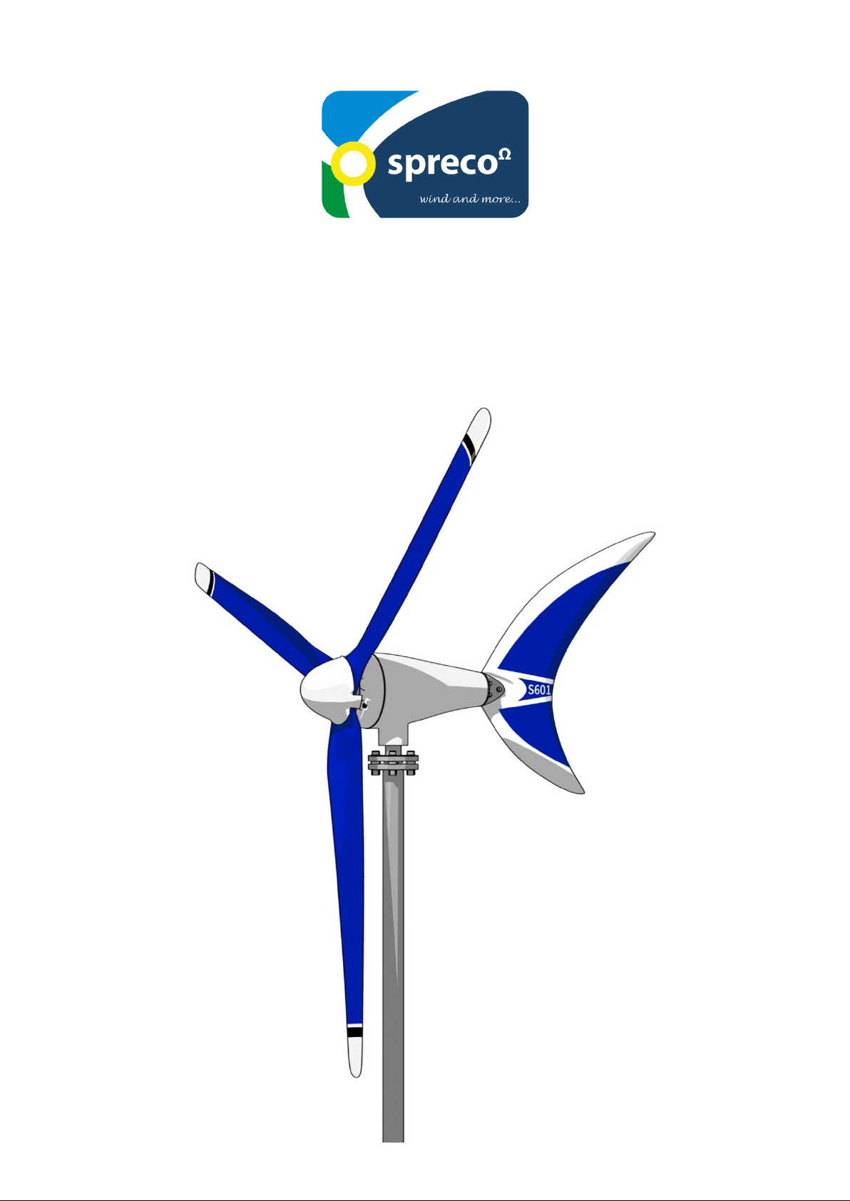
User and installation guide
SHARK 12V / 24V / 48V
Page 2

2
Dear customer!
Congratulations on your decision to purchase the SHARK S601. He is
distinguished from conventional wind generators with high security,
enormous efficiency and very low noise level over the entire range.
You also benefit from our more than 30 years of experience with various
wind generators used on the high seas (Silent Wind from Spreco on
sailing boats).
Electric current is particularly important there and ensures safety and
comfort on board.
Please note that this user manual is part of the product. We recommend
that you read this manual carefully before installing the SHARK S601 and
follow the instructions. Please keep this user manual in a safe place.
Good luck and always enough wind wishes you your
Spreco Team
Page 3

3
Index:
1. Use and area of application .................................................................................................................. 4
2. Safety instructions ............................................................................................................................... 5
2.1 Mechanical hazards ........................................................................................................................... 5
2.2 Electrical hazards ............................................................................................................................... 6
2.3 Installation hazards ............................................................................................................................ 6
3. Technical data ....................................................................................................................................... 7
3.1 Wind generator .................................................................................................................................. 7
3.1.1 Electrical data .................................................................................................................................. 7
3.1.2 Mechanische Daten ......................................................................................................................... 7
3.2 Charge controller ............................................................................................................................... 8
3.2.1 Electrical data .................................................................................................................................. 8
3.2.2 Mechanical data.............................................................................................................................. 8
3.4 Power curve ....................................................................................................................................... 9
3.5 Dimensions ......................................................................................................................................... 9
4. Scope of delivery................................................................................................................................. 10
5. Functional description ........................................................................................................................ 11
6. Cable sizing ......................................................................................................................................... 12
7. Assembly ............................................................................................................................................. 13
8. Commissioning .................................................................................................................................... 17
9. Start and stop ..................................................................................................................................... 19
10. Charging indicator ............................................................................................................................. 19
11. Checks ............................................................................................................................................... 20
11.1 Rotor blades .................................................................................................................................... 20
11.2 Screw connections .......................................................................................................................... 20
11.3 Bearings, seals ................................................................................................................................ 20
11.4 Corrosion protection ...................................................................................................................... 21
11.5 Mast construction ........................................................................................................................... 21
11.6 Electrical System ............................................................................................................................. 21
12. Maintenance ..................................................................................................................................... 22
Page 4

4
13. Troubleshooting ................................................................................................................................ 22
14. Warranty ........................................................................................................................................... 24
1. Use and area of application
You achieve the greatest regenerative energy yield by the combination of wind
generator and solar module, whereby you save the gained energy in a battery
system and thus use the daylight and the available wind energy. Our charge
controller is designed to connect an additional 300Wp max. solar power (hybrid
charge controller).
The possible applications are diverse and suitable for stationary and mobile standalone systems via the battery voltage with a 230 V inverter.
Our wind generator is very efficient and aerodynamic. If the energy requirement
is higher, several SHARK S601 wind generators can be used in parallel. Due to
the low noise level, the SHARK S601 wind generator can be installed in
residential areas and on sailing yachts without disturbing the neighbors.
The supplied hybrid charge controller is designed with inputs for solar panels and
wind generator for the SHARK S601.
Another advantage of the SHARK S601 is that almost no electronics are installed
in the housing. This drastically reduces maintenance work.
The electric energy is conducted via three cables down to the regulator. The handlaminated carbon fiber blades of the new generation have been successfully tested
in the wind tunnel according to the DIN EN-61400-2 standard. You don't have to
worry about the SHARK 601 in storms because a specially developed storm brake
is installed. The brake procedure starts at 130 degrees Cᵒ on the stator, after
cooling it is switched on again.
For maintenance work please use the enclosed stop switch.
Application examples:
Electric car charging station in connection with PV
Stationary / mobile island systems
Measuring stations on grid / off grid, Emergency call systems, Street lighting,
Development aid projects, Wireless-Lan Access Points, Holiday homes with
230V (110V) inverter or wherever there is no power connection.
Page 5
5
2. Safety instructions
Wind generators are due to the high speed and the voltage generated not harmless.
Therefore, please read the following safety instructions with great care:
2.1 Mechanical hazards
The rotating rotor poses a great danger. Above a certain wind speed, it even
appears transparent so that the danger is not visually recognized. Our blades are
coated with three colors so that they can be better recognized visually. Never touch
the rotating blades! Never try to stop the rotating blades by hand!
Please keep your distance!
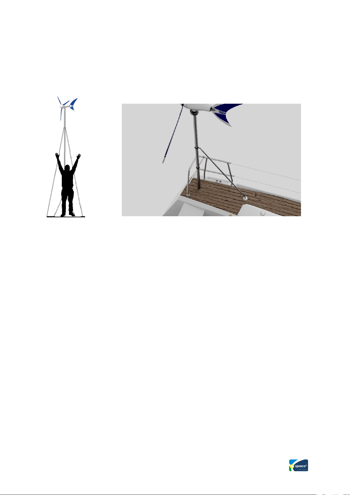
Install the generator only in places where it is impossible for anyone to reach out
to it! This is particularly important on sailing yachts. Install the wind generator at
a sufficient height from the deck.
The rotor blades are made from hand-laminated carbon fiber material that can
withstand even hurricane-like wind speeds. Always keep away from the rotating
blades to avoid injuries.
Parts or lines flying around can still break the rotor blades. If a rotor blade is
damaged, the system must be shut down by manually operating the stop switch.
Damage to a rotor blade can result in significant imbalances, so that the entire
mast on which the wind generator is mounted can be endangered. Please take this
into account when choosing your installation site, so that it is really safe. During
assembly, the three electrical cables from the generator must be disconnected and
short-circuited, or a blade must be tied to the mast.
The mast and the mast struts must be such that they can withstand the wind forces
and varying loads. Furthermore, the mast foot and struts should be installed in
such a way that vibrations that may arise are not amplified. It is recommended to
consult a specialist.
Page 6
6
2.2 Electrical hazards
Only connect all components if you have the relevant experience. Complete all
electrical connections before the wind generator runs for the first time. These
voltages / currents can cause burns or fire if safety is disregarded.
Caution with pacemakers, etc.! Never touch stripped cable ends. The current
strength when charging batteries can reach more than 50 A direct current (DC).
All cables, electrical components and connection points must be able to withstand
a minimum of 60 A at 12 V. For protection, a 60 A fuse at 12 V (30 A at 24 V)
must be installed in the supply line (+) to the battery, as close as possible to the
battery.
Warning: Lines with insufficiently dimensioned cross sections can heat
up to such an extent that a fire can occur.
Cables must be laid so that there is no mechanical damage to the cables. A frayed
cable poses security risks.
Warning: Sparks can occur when connecting the batteries.
Avoid short-circuiting the batteries. Always make sure there is adequate
ventilation!
It must be ensured that the electrical installation is only carried out by people with
expertise.
Before a storm, the SHARK S601 should be braked using the stop switch built
into the charge controller. In the event of an oncoming hurricane, it makes sense
if a rotor blade is tied to the mast. This is especially recommended when operating
the SHARK S601 on a sailing yacht.
2.3 Installation hazards
Only use mast constructions that can withstand the loads generated by the wind
generator and its wind pressure, as well as movements of the ship (forces can add
up) at any wind speed.
Work on the mast should preferably be carried out on a windless day. No one
should be in the danger area of the generator mast.
Page 7
7
The battery must be electrically isolated from the system during all work
on the system. The rotor must not run loose during work by tying up a rotor blade,
otherwise the charge controller may be destroyed. The electrical installation must
be completed.
3. Technical data
3.1 Wind generator
3.1.1 Electrical data
Generator type
Permanent magnet generator, 3-phase,
AC
Nominal voltage
12 V DC / 24 V DC / 48V DC with
boost charge controller
Rated capacity
600 Watt 700 Watt 800 Watt
Nominal wind speed
Ca. 14 m/s
Start-up wind speed
Ca. 3 m/s
Start of charging
Ca. 200 Upm
3.1.2 Mechanical data
Safety test in the wind tunnel
122 km/h
Rotor diameter
1,50 m
Number of blades
3
Blade weight
250g / Blade
Blade material
Carbon Cfk
Hand laminated
Speed range
200 - 950 rpm
Page 8
8
Weight
Ca. 12 kg (Generator)
Color
White, powder coated 2 layers
Warranty
24 Months
3.2 Charge controller
Charging criteria are set using the supplied external hybrid charge controller with
boost function.
The charge end voltage is adjustable for lead acid, gel, AGM, and lithium
batteries. Please follow the instructions of the battery manufacturer!
Braking process: electronically depending on the individual parameter setting,
manually with the inbuilt stop switch or with the extended external switch.
3.2.1 Electrical data
System voltage
12V
24V
48V
Max. Power input wind generator
600 W 700W 800W
Max. Current input wind generator
32 A 25A 12,5A
Max. Power input solar
300 Wp at 12 V
Max. Current input solar
20 A 10 A 5 A
Max. Open circuit voltage input solar
18 V DC 36 V DC 72 V DC
Multi function display + LED
W, V, A, kWh, Ah,
3.2.2 Mechanical data
Weight
2.8 kg (charge controller)
Package dimensions
220 x 150 x 82 mm
Page 9
9
Warranty
24 Months
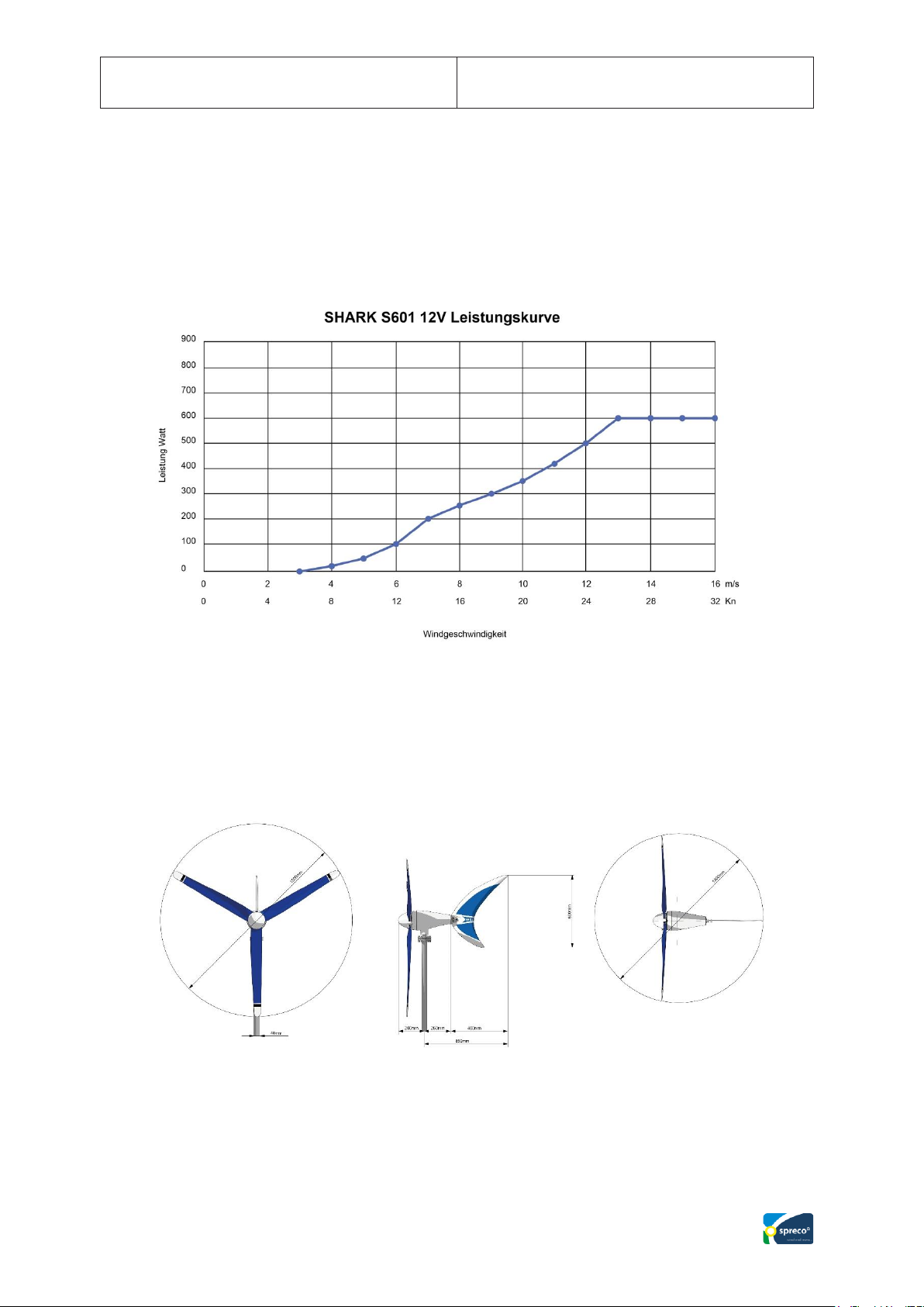
3.4 Power curve
3.5 Dimensions
Page 10
10
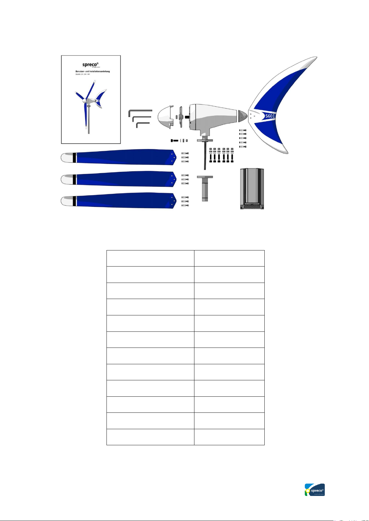
4. Scope of delivery
Generator, powder coated
1
Fin, Carbon
1
Hub
1
Nose cone, ABS
1
Rotor blade, Carbon
3
Boost charge controller
1
Quickguide
1
Screw set rotor blades
1
Screw set Fin
1
Allen key 4mm
1
Allen key 5mm
1
Allen key 8mm
1
Page 11

11
All information is reliable. However, the manufacturer assumes no responsibility
for inaccuracies or imperfection. The user of this information as well as the
product bears full responsibility and risk.
All specifications are subject to change without prior notice.
5. Functional description
All wind generators use the kinetic energy contained in the wind. This energy is
partially (theoretically 58%) converted into a rotary motion by the rotor blades
and then converted into a 3-phase alternating current in the generator. The power
of the wind energy increases proportionally to the 3rd potency with the wind
speed. That means doubling the wind speed leads to an eightfold increase in
performance. This is particularly important in stormy weather.
Our rotor blades are made from high-tensile carbon fiber mats, hand laminated
with epoxy resin. This material offers the highest strength with the lowest weight.
As a result, the newly developed blades are extremely light and cannot be
destroyed by wind forces during operation.
For normal operation, we have added additional safety to our controllers with an
electronic and manual brake system.
There is also a patented strong wind brake in the generator housing. If the current
is drained, the stator can heat up considerably and there is a risk of fire. the brake
is then activated by a bimetal switch and, after cooling the brake is released again.
Page 12
12
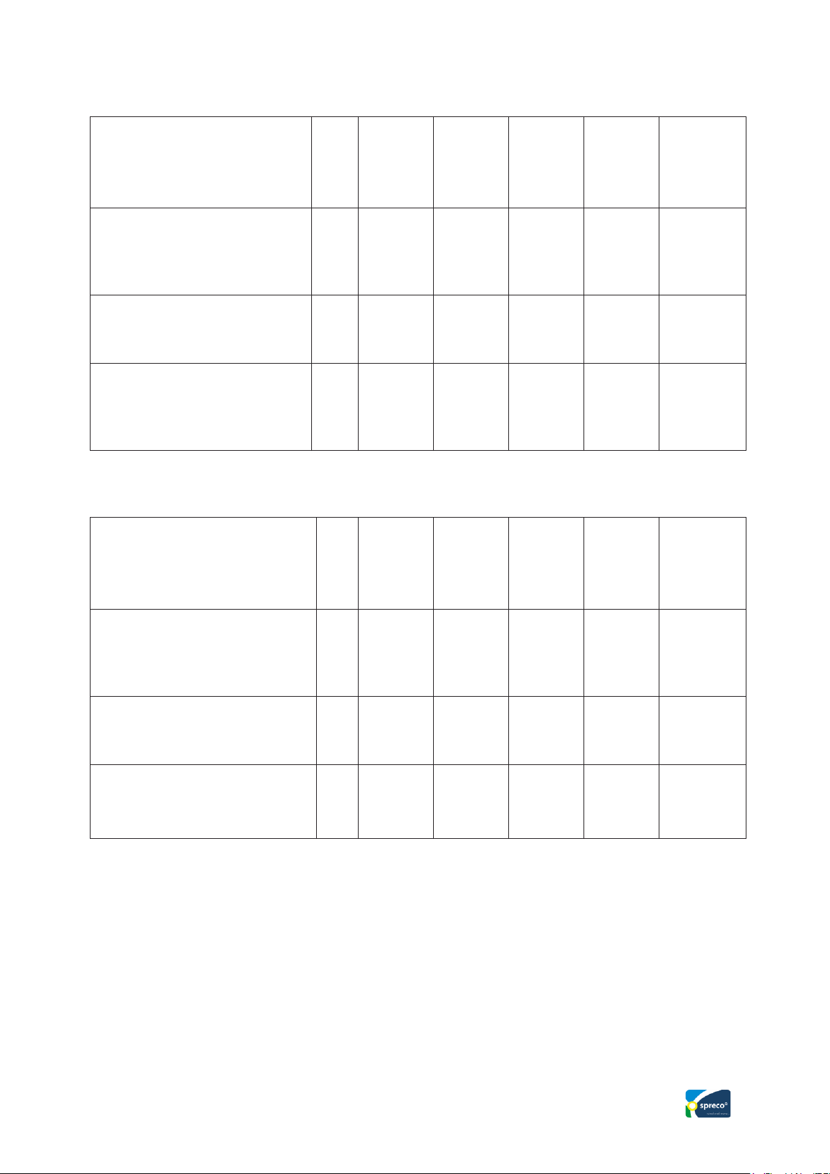
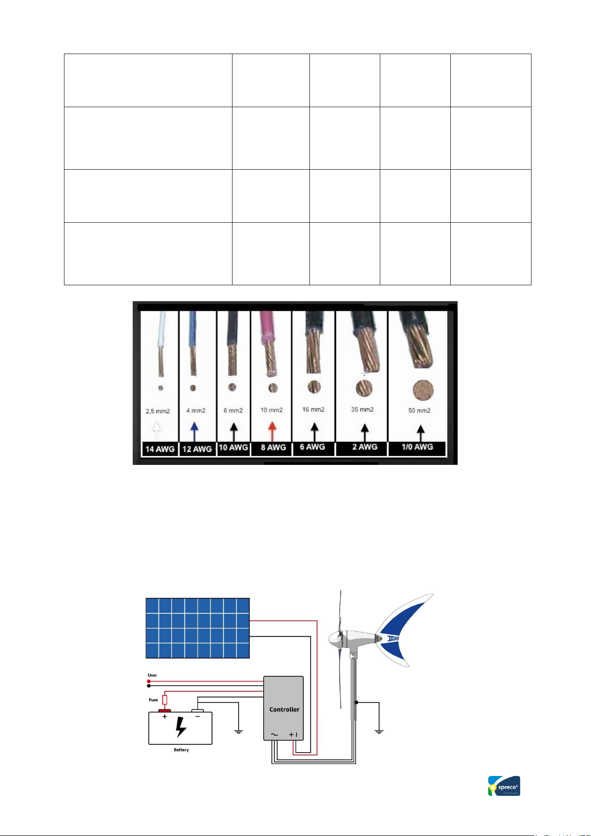
6. Cable sizing
System voltage 12 Volt:
Distance from wind
generator to charge
controller in m
0 - 9
10 – 19
20 – 29
30 – 44
45 – 69
70 – 110
Cable cross section in mm2
AWG
6
10
10 8 16 6 25 4 35 2 50
1
Distance from charge
Controller to Battery in m
0 - 9
10 – 19
20 – 29
30 – 44
45 – 69
70 – 110
Cable cross section in mm2
AWG
10 8 16 6 25 4 35 2 ---
---
---
---
System voltage 24 Volt:
Distance from wind
generator to charge
controller in m
0 -
10
11 – 19
20 – 29
30 – 44
45 – 69
70 – 110
Cable cross section in mm2
AWG
2.5
14
4
12
6
10
10 8 16 6 25
4
Distance from charge
controller to Battery in m
0 - 9
10 – 19
20 – 29
30 – 44
45 – 69
70 – 110
Cable cross section in mm2
AWG
10
8
16
6
25
4
35
2
---
---
---
---
Page 13
13
Electrical installation example
System voltage 48 Volt:
Distance from wind
generator to charge
controller / inverter in m
0 - 29
30 – 79
80 – 99
100 – 150
Cable cross section in mm2
AWG
2.5
14
4
12
6
10
10
8
Distance from charge
controller to Battery / Inverter
in m
0 – 29
30 – 69
70 – 99
100 – 150
Cable cross section in mm2
AWG
4
12
6
10
10 8 16
6
7. Assembly
Before the wind generator assembly, you should find the right location. This is
often the most difficult task. Ideal would be if the rotor blades were always flowed
evenly. This presupposes that the wind generator is installed high enough and free
of obstacles.
Page 14

14
Stationary assembly: The required assembling height depends on how much the
surrounding objects deflect the wind from his main direction. To do this, you can
first carry out a simple experiment by attaching a plastic tape (approx. 3 m long
and 4 cm wide) to a rod that is at least 4 m long, at the upper end and additionally
attach a second tape two meters lower.
If the top band blows perpendicularly or moves back and forth up to 30 degrees,
you have found a suitable location. If the tape moves more or even winds around
the rod, the location is unsuitable. This experiment is only a rough statement and
should only be carried out with light wind. We recommend doing several tries to
get a better feel for it. You do not need to do this if the wind generator is
completely free.
Page 15
15
Assembly on a sailing yacht: The assembling height must be chosen so that no
crew member is endangered by the rotor. The mechanical anchoring of the base
point of the generator mast must be able to withstand the mechanical loads that
occur, especially with rough seas. We advise an additional rigging, to the rail or
to the deck of the ship. In order to avoid vibrations, we recommend to set the mast
fixation point about 25 cm bellow the blade tip.
Note: Please note that the SHARK S601 can never achieve its full performance if
it is not in the main wind direction or is deflected. Therefore, it is important to
find a suitable location that is free of obstacles in the prevailing wind direction!
Once you have found the right location, the right mast with accessories must be
selected.
The mast outer diameter should be 48 mm and made of stainless steel, with a wall
thickness of at least 2.5 mm. Please also consider possible maintenance work.
Grounding the mast is also recommended. The grounded sail mast is suitable on
sailing yachts.
When the mast is installed in the correct location, the relatively simple assembly
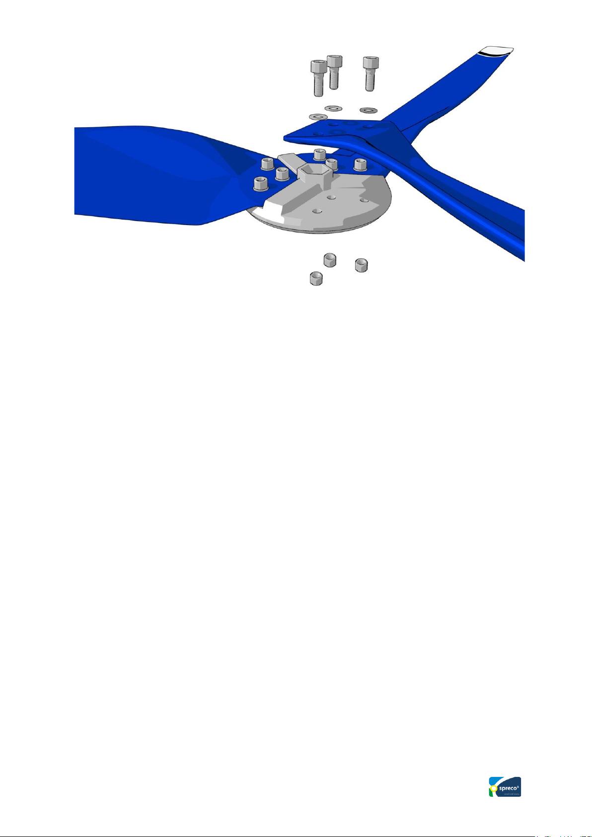
of the SHARK S601 can begin. To do this, first mount the three carbon fiber
blades with the respective screw set on the Hub. Note - The screws must be
properly tightened (the tightening torque is 7 - 8 Nm.) Please see our videos in the
download area.
Page 16
16
An incorrect tightening torque represents a considerable safety risk. Check the
rotor blades regularly for tightness, optically and mechanically!
Should it happen that a blade is damaged by external influences, a single blade
can be ordered by notifying the exact weight of the remaining good blades.
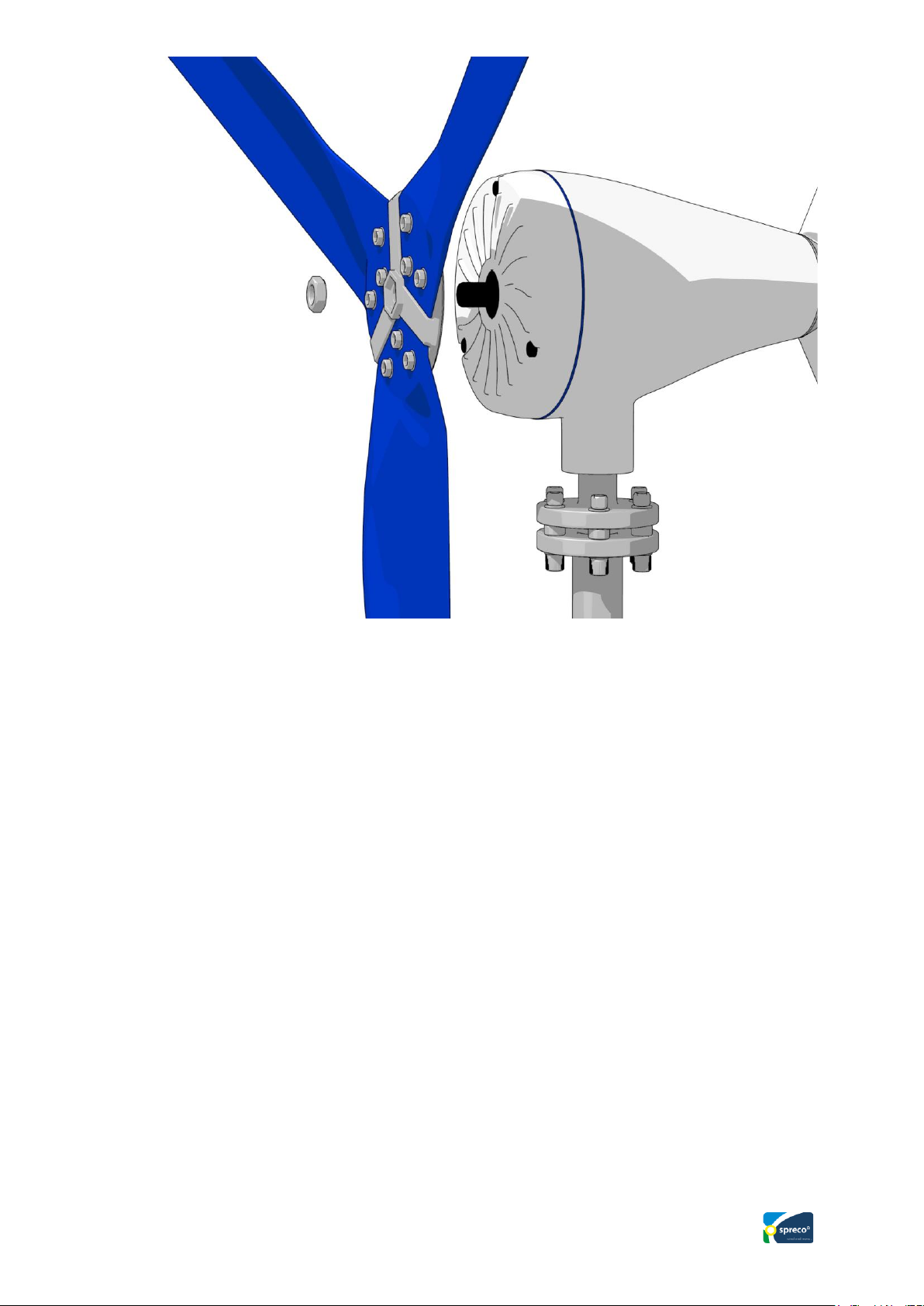
After the blade assembly, the blade set is plugged onto the generator axis and
screwed down with the enclosed nut and Allen key. Then press the nose cone onto
the Hub until it is fully engaged (see assembly video).
Page 17
17
Attention: During this work on the rotor it must be ensured that the rotor cannot
start. The 3 wired cable must be short-circuited. Otherwise, the rotor can start
running and cause injuries.
If you remove the SHARK S601 from the mast to replace the rotor blades, you
must ensure that the blades do not start moving before you have finished the work
(3 AC cable short circuit).
8. Commissioning
Before releasing up your SHARK S601, please check the correct assembly and
installation using the following checklist:
Page 18
18
O.K.
Mast construction (not included);
Check according to the enclosed instructions, in particular all screw
connections, anchoring, vertical alignment.
Earthing and lightning protection connected according to local regulations?
Electrical installation:
Check the condition of the battery and connect it to the charge controller with
the correct polarity
Charge controller:
Is the charge controller securely attached to the installation site? (Choose
cool place)
Connect the battery with the correct polarity, otherwise the controller will be
destroyed. Caution: Always connect the battery to the charge controller first!
Are all screw terminals tightened?
Is the external stop switch set to ON?
CAUTION: No voltage may be applied to the stop switch socket !! This
destroys the controller. Only connect the enclosed cable harness with socket
there. (see installation video in the download)
Automatic circuit breaker:
Automatic circuit breaker, at least 60 amps, connected between battery and
charge controller?
Cables:
Are all cables / lines connected according to the connection diagram?
Is the cables polarity checked at all connection points?
Is the three-pole cable from the generator to the charge controller
connected?
Are the cables crimped correctly?
Page 19
19
Mast mounting:
Is the damping rubber correctly screwed to the flange and checked for
tightness?
Rotor blades:
Is the assembly carried out according to the instructions?
Blade Hub:
Is the hub mounted on the generator shaft?
Has the central fastening screw been tightened to 30 Nm?
If our charge controller is not used:
Connection to the three-phase rectifier (optionally available from us in the shop)
can be found in the package Leaflet. This enables you to provide the energy
generated by the wind generator to downstream systems. e.g. Inverter input,
energy management systems, island systems.
NOW YOU CAN GET STARTED!
9. Start and stop
Set the external stop switch to “ON”. If the plus / minus cable is connected to the
battery with the correct polarity, the wind generator should now run if there is
enough wind available. You can see this on the LCD display of the charge
controller. (blade symbol turns). Small stop switch should be provided by the
customer or optionally ordered from us in the shop.
10. Charging indicator
The amount of charge is shown on the charge controller display.
Page 20

20
11. Checks
Your SHARK S601 is designed to last for years without any maintenance.
However, simple and regular checks are always part of it to ensure the necessary
operational safety.
Your safety is very important to us!
Before you start the check, make sure that during all work on the system, the rotor
is brought to a standstill and the battery is disconnected from the system.
The following checks should be carried out every 12 months:
11.1 Rotor blades
Check the rotor blades for possible damage, such as broken edges, surface
damage, cracks. If you find any damage, the generator must not be operated.
Check the screw connection after one day of operation and then after one month.
You can then switch to longer intervals.
11.2 Screw connections
Check all screw connections that are accessible from the outside for tightness or
correct tightening torque. Check the rotor blade bolts, the central hub nut and the
mast attachment in particular.
11.3 Bearings, seals
The bearings of the generator shaft and the bearing for the Yaw shaft are designed
as permanently lubricated ball bearings. Please check these bearings for ease of
movement, bearing play and tightness. Please replace defective bearings or have
them replaced by a service center. The Shark rotor is supported on both sides and
therefore has a longer service life and is quieter.
Page 21
21
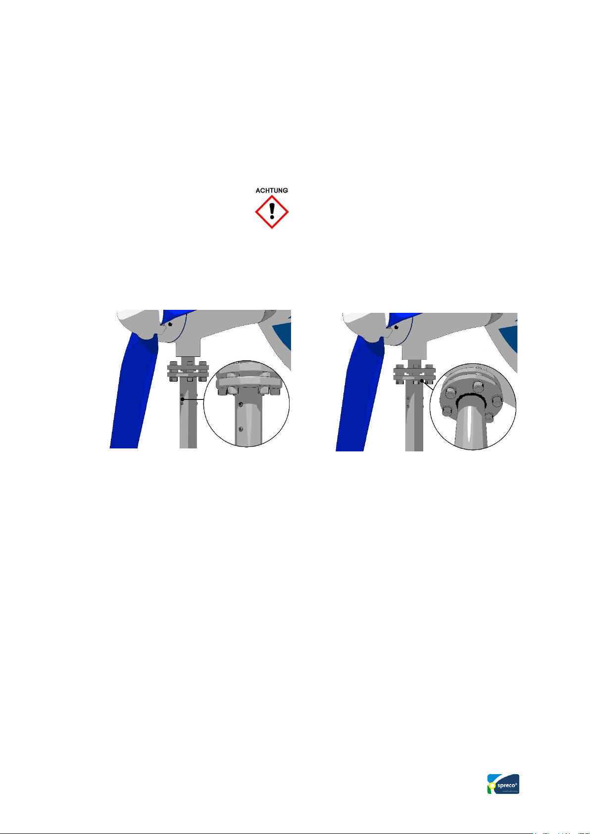
SHARK welded to the mast
11.4 Corrosion protection
All housing parts consist of a seawater-proof aluminum alloy and are additionally
treated with a powder coating (2-layer structure). If this layer is damaged, there is
a risk of corrosion. Please touch up with a suitable varnish.
11.5 Mast construction
The Shark S601 flange must be attached to the mast! Either with 2 screws (picture
1) or welded on (picture 2).
11.6 Electrical System
Please bring the wind generator to a standstill first so that all lines are free of
voltage.
Check all connection points for tight fit and corrosion. Correct any corrosion that
may have occurred and treat with contact spray. You should pay particular
attention to the battery connections. These are to be cleaned and treated with pole
grease. The battery must be checked and repaired according to the manufacturer's
instructions. If there are several batteries, you should also check for different
capacities (self-discharge). Only connect the same size (Ah) and the same aged
batteries in parallel!
SHARK attached with 2 screws
Page 22
22
12. Maintenance
There is no maintenance work on the SHARK S601.
The SHARK S601 was designed for years of trouble-free operation. This goal was
very important to us.
13. Troubleshooting
You should be able to solve a problem yourself with the following checklist:
Wind generator does not start:
Possible cause
Test
Fix
Stop switch is set to
"STOP"
set to "RUN"
Generator shaft stiff
turn by hand
Connecting cable
Generator to charge
controller damaged,
Short circuit of ACElectric wire,
Generator short circuit,
Customer service
Wind generator does not deliver power:
Possible cause
Test
Fix
Too low wind
measure wind speed at
rotor height.
(Wind speed at the top of
the main mast
is higher)
charging starts depending
on the charge level of the
setting
Electrical conductance is
broken
cables and devices
or devices
Page 23

23
Fuse interrupted
Check conductance of
fuse
automatic circuit breaker
to cool down
Built-in
Current collector (slip
ring unit) has
no contact
Check carbon brushes and
make springs usable
Battery is not fully charged:
Possible cause
Test
Fix
Battery old, defective
Battery voltage and
capacity with Battery
tester (Hardware store
available) check.
Replace battery, refill
Fuse defective
Check conductance
Replace the defective fuse
and find the reason for the
defect
Charge controller
incorrectly connected
connect properly
Charge controller, stop
switch is set to "STOP"
"ON"
Follow instructions in
manual
Generator defective,
cable short circuit
Check AC voltage at the
input of the charge
controller
After disconnecting the
charge controller, check
all three cables for shortcircuit interruptions
Charge controller
defective,
battery reverse polarity
Check settings according
to manual
replacement
Page 24

24
14. Warranty
The company Bach Energiesysteme guarantees that all of the devices it sells have
no defects in materials and workmanship within the warranty period from the time
of purchase.
The following warranty periods apply:
SHARK S601 24 Months
BOOST charge controller 24 Months
Should defects in the device become apparent during this period, which can be
attributed to material or processing errors, Bach Energiesysteme will repair or
replace the device itself or defective parts in accordance with the following
conditions, without calculating the labor and material costs.
Warranty services are only provided if the warranty certificate in the appendix to
these installation instructions is completely filled out and the original invoice from
the dealer is presented.
The warranty does not cover: Regular inspections, maintenance, repair or
replacement of parts due to normal wear and tear.
Transport, freight costs and freight risks that are directly or indirectly related to
this device guarantee.
Travel expenses to and from the repair center, troubleshooting, diagnostics and
repair work.
Damage caused by misuse and failure to operate the device, especially when
installed on an unsuitable mast. In the event of damage, the buyer must provide
proof that the installation was carried out on a suitable mast.
Damage caused by force majeure or other causes for which Bach Energiesysteme
is not responsible, in particular lightning strikes, flooding, snow loads, fire,
hurricanes, etc.
If the delivery item has to be dismantled as part of the warranty and rebuilt after
repair or replacement, dismantling and reconstruction costs will not be borne by
Bach Energiesysteme. Bach Energiesysteme company alone decides whether
repairs or new deliveries are appropriate or necessary. If neither repairs nor new
deliveries are possible, the client is only entitled to withdraw.
Unless mandatory law provides otherwise, the buyer's claims against Bach
Energiesysteme are limited to these warranty provisions, and neither Bach
Page 25
25
Energiesysteme nor the distributors of the products assume liability for direct or
indirect damage.
Otherwise, the "General terms of delivery for products and services of the
electrical industry" apply in Germany.
Name
Adress
Purchase date
SHARK S601 Serial Nr.
Boost Charge Controller
Serial Nr.
Dealer
Dealer adress
SPRECO Windgenerator
Bach Energiesysteme
Brand 74
D-91729 Haundorf
Telefon: +49 (0)4193/8709925
Telefon: +49 (0)9837/9769838
Mail: [email protected]
Web: www.sprecowindgenerator.com
 Loading...