

Sportplus SP-HT-2507-TS Instruction Manual

INSTRUCTION MANUAL
Home Trainer
Bedienungsanleitung
Heimtrainer
UK
DE
1
SP-HT-2507-TS

Dear Customer,
Congratulations for choosing a SportPlus product. We have every expectation that
you will be fully satised with your new purchase.
To guarantee optimal function of this product, please adhere to the following
instructions:
Before using this product, please read the manual carefully.
•
The product has been designed with safety in mind. Nevertheless, please
•
read the safety instructions carefully and use the equipment only as
described in the manual. Taking these precautions will prevent hazardous
situations and personal injury.
Please retain this manual for future reference.
•
Should you pass on this product, ensure to include the corresponding
•
instruction manual.
CONTENTS
1. TECHNICAL DATA ......................................................................................... 3
2.
SAFETY INSTRUCTIONS ........................................................................ 3
3. ASSEMBLY DIAGRAM .................................................................................. 6
4. PARTS LIST ...................................................................................................
7
5. ASSEMBLY INSTRUCTIONS ........................................................................ 9
EXERCISE COMPUTER OPERATION MANUAL .......................................13
6.
7. TRAINING TIPS ............................................................................................18
IMPORTANT ADVICE FOR TRAINING .................................................. 19
WARM-UP / STRETCHING / COOL-DOWN ............................................... 20
8. MAINTENANCE & CLEANING .................................................................... 21
9. ADVICE FOR THE DISPOSAL OF PACKAGING ....................................... 21
10. COMPLAINTS & WARRANTY ..................................................................... 22
CUSTOMER SERVICE ................................................................................ 22
WARRANTY CONDITIONS ......................................................................... 23
2

1. TECHNICAL DATA
2. SAFETY INSTRUCTIONS
TECHNICAL DATA
Specications of the product
Dimensions (L x B x H): 80 x 51 x 137 cm
•
Total Weight: 25 kg
•
Brake system: speed-dependent
•
Movement pattern: dependent
•
•
Class: H.C
Max. Weight of User: 100 kg
•
Specications of the computer
Number of batteries: 2
•
Battery type: R03 AAA Micro / 1.5V
•
SAFETY INSTRUCTIONS
PURPOSE
The product is intended for domestic use only and is not suitable for
•
professional or medical use.
The maximum weight of a person using this product is 100 kg.
•
If used regularly, this home trainer can help you to develop your cardio-
•
vascular function, as well as leg and hip muscles. In combination with a
suitable nutrition it can also help you to reduce weight.
ENGLISH
DANGER FOR CHILDREN
Parents and other supervisory persons should be aware of their
•
responsibility for children using this equipment. Because of the natural play
instinct of children and their eagerness to experiment; those persons have
to anticipate usage and situations for which this product is not intended.
Children may be unaware of the potential hazards posed by this product.
•
Ensure that unsupervised children are kept clear from the equipment at
all times; this is not a toy. Equipment should be stored safely away from
children and pets.
Do not let unsupervised children near this equipment. A responsible adult
•
should make the suitable equipment settings and supervise activity at all
times.
Beware! The packaging material is not suitable for children. There is a
•
danger of suffocation!
ATTENTION – RISK OF INJURIES
Do not use the product if it is damaged or defective. In the case of which,
•
please consult a qualied technician or our service centre.
Check the product on every occasion prior to its use. Defective parts
•
may impair the use of the machine; these should be repaired or replaced
3

immediately.
This equipment is to be used by only one person at any one time.
•
Use the product only on even and non-slipping surfaces. Do not use it near
•
water and always allow sufcient surrounding space to ensure safety.
This equipment has many moving parts; keep your ngers and other limbs
•
clear of these parts. Failure to do so could cause injury. Do not insert any
implements into openings in the equipment.
ATTENTION – PRODUCT DAMAGE
Please do not attempt to alter or modify the product in any way. Only
•
use original spare parts. Repairs should only be carried out by qualied
technicians – unauthorized repairs could put the user at risk. Use this
product only as described in this manual.
Protect the product from splashes, humidity, high temperature and direct
•
sunlight.
ADVICE FOR BATTERY HANDLING
Batteries can be extremely dangerous if swallowed. Therefore, keep
•
batteries away from children. If a battery has been swallowed, seek medical
help immediately.
Remove batteries when they are out of charge or if the device should not
•
be used for a longer period of time, in order to avoid accidents due to
battery leaking.
Do not recharge, disassemble ou throw batteries into the re. RISK OF
•
EXPLOSION.
Pay attention to the polarity marks (+) and (-). Always replace all batteries,
•
do not mix used batteries with new ones, or with batteries of a diffent type!
The use of alcaline batteries is preferrable, because they have a longer life
•
than zinc coal batteries.
It is necessary to replace the batteries when the display becomes weaker
•
or completely blank.
ADVICE FOR THE ASSEMBLY
The product should be carefully assembled by a responsible adult. If in any
•
doubt, please refer to a technically qualied person.
Before commencing with assembly, read the safety and assembly
•
instructions carefully.
Choose a clear, at surface to begin your assembly. If possible, use an
•
underlay to protect the assembly space from dirt and scratches. Remove
all packaging materials and lay out all the parts. This will help you visualize
your nished product and simplify the procedure.
Using the ‘Parts List’ ensure that no parts are missing. Dispose of all the
•
packaging materials when the assembly is completed.
Assemble the product carefully. There is always a risk of injury when using
•
tools for technical work.
4

During assembly, maintain a safe working environment. Keep tools and
•
packaging materials clear of your workspace. Foils and plastic bags are
potentially hazardous to children (danger of suffocation)!
When the assembly is complete, ensure that all nuts, bolts and fasteners
•
are correctly engaged and tightened.
If required, use an underlay to protect the oor (not included). The rubber
•
feet of the product could mark or damage some surfaces.
ENGLISH
5
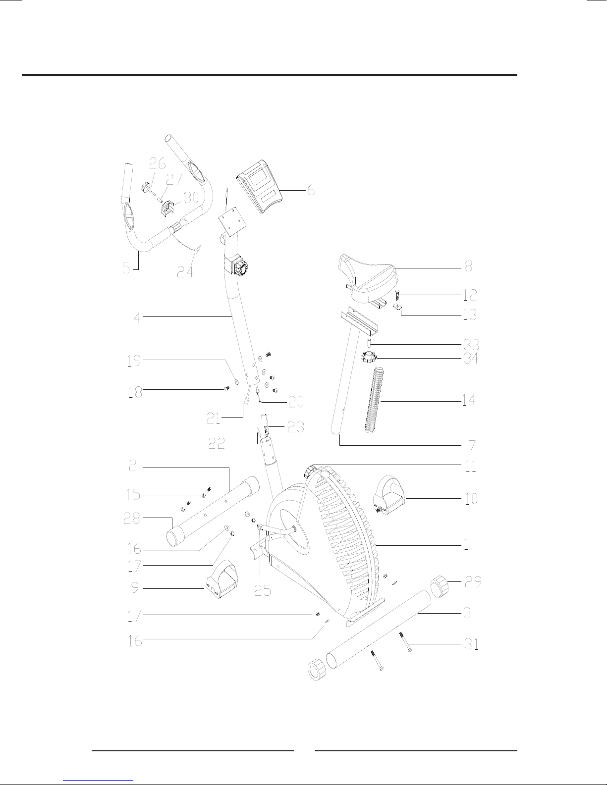
3. EXPLODED DIAGRAM
6

4. PARTS LIST
ENGLISH
NO
1
2 Front Stabilizer 1 PC
3 Rear Stabilizer 1 PC
4 Front Post 1 PC
5 Handlebar W/GripW/Grip 1 PC
6 Computer 1 PC
7 Seat Post 1 PC
8 Seat 1 PC
9 Left Pedal 1 PC
10 Right Pedal 1 PC
11 Quick Release Adjustment KnobAdjustment Knob 1 PC
12 Carriage Bolt M8*60 1PCS
13
14 Seat Support Sleeve 1PCS
15
DESCRIPTION Q’TY
Main Frame 1 PC
Flat Washer 1PCS
M10x50mm Carriage Bolt50mm Carriage Boltmm Carriage Bolt 2 PCS PCSS
16
17 M10 Domed Nut 4 PCSPCS
18
199 Ø22 Curve Washer22 Curve Washer Curve Washer 3 PCS PCSS
20 Tension Knob + Upper Tension Cable+ Upper Tension Cable Upper Tension Cablepper Tension Cableable 1 PC
21 Middle Computer Wire 1 PC
222 Lower Computer Wire 1 PC
23 Lower Tension Cableension Cable 1 PC
24 Hand Pulse Wire 1 PC
25 Crank Arm 1 PC
266 T Knob 1 PC PC
27 Allen Bolt M8*200 1 PC
28 Front Stabilizer End Cap Stabilizer End CapCap 2 PCS
299 Rear Stabilizer End CapStabilizer End CapEnd Cap 2 PCS PCSPCS
30 Clamp
31 M10x75mm Carriage Bolt75mm Carriage Boltmm Carriage Bolt 2 PCS PCSS
Ø25 Curve Washer25 Curve Washer Curve Washer
M8*15mm Allen Bolt
4 PCS PCS
3 PCS PCSS
1 PC
32 Upper Computer Wire Computer Wire 1 PCS PCSS
33
34 Adjusted Knob 1PCS
Bushing 1PCS
7
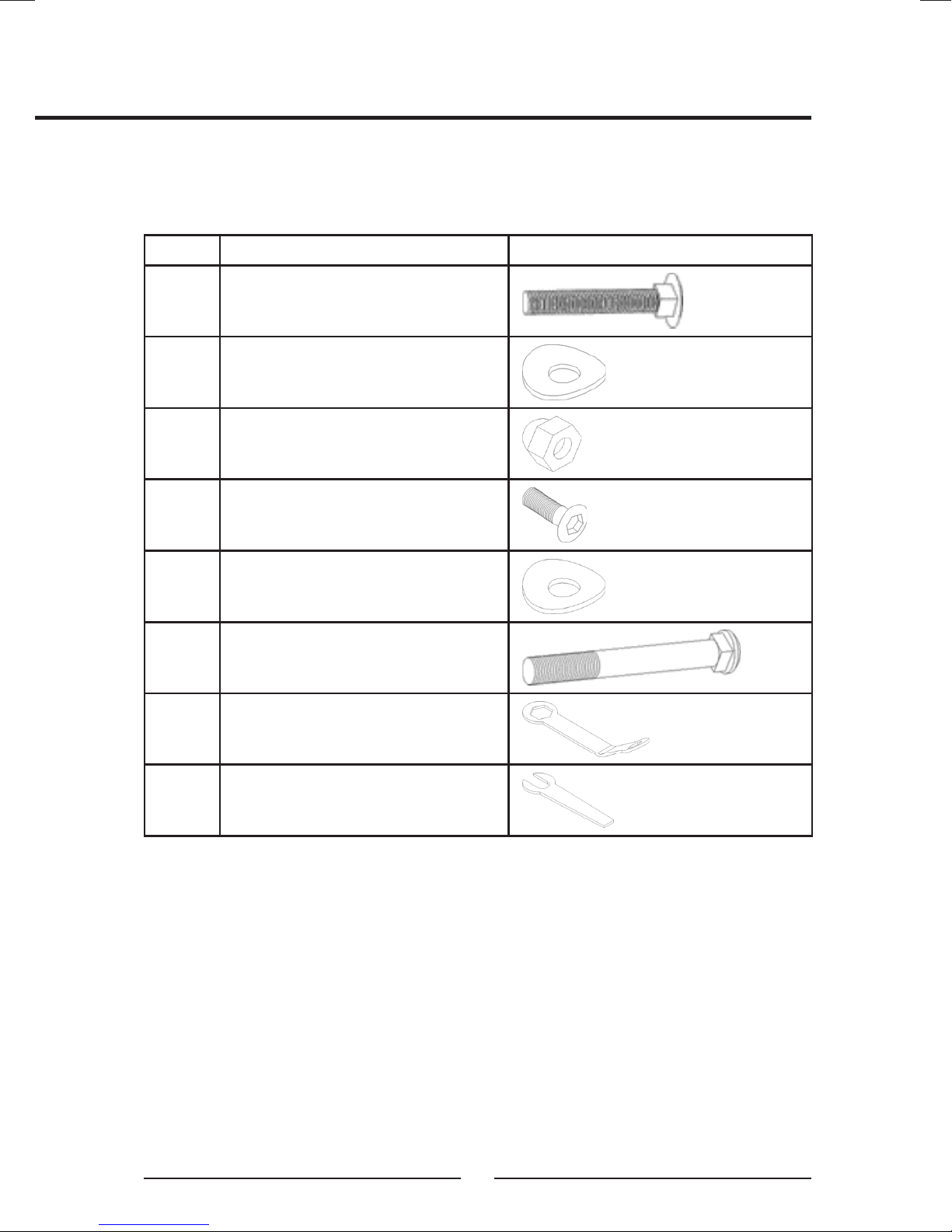
HARDWARE PARTS LIST
Key# Description Quantity
#15.
Carriage Bolt M10*50
#16. Curve Washer Ø10.5*Ø25*T1.5Ø10.5*Ø25*T1.510.5*Ø25*T1.5Ø25*T1.525*T1.5
#17. Domed Nut M10
#18. Alley Bolt M8*15
#19. Curve Washer Ø10.5*Ø25*T1.2Ø10.5*Ø25*T1.210.5*Ø25*T1.2Ø25*T1.225*T1.2
#31. Carriage Bolt M10*75
Box Wrench 13/17
2
4
4
3
3
2
Spanner 15
1
1
8
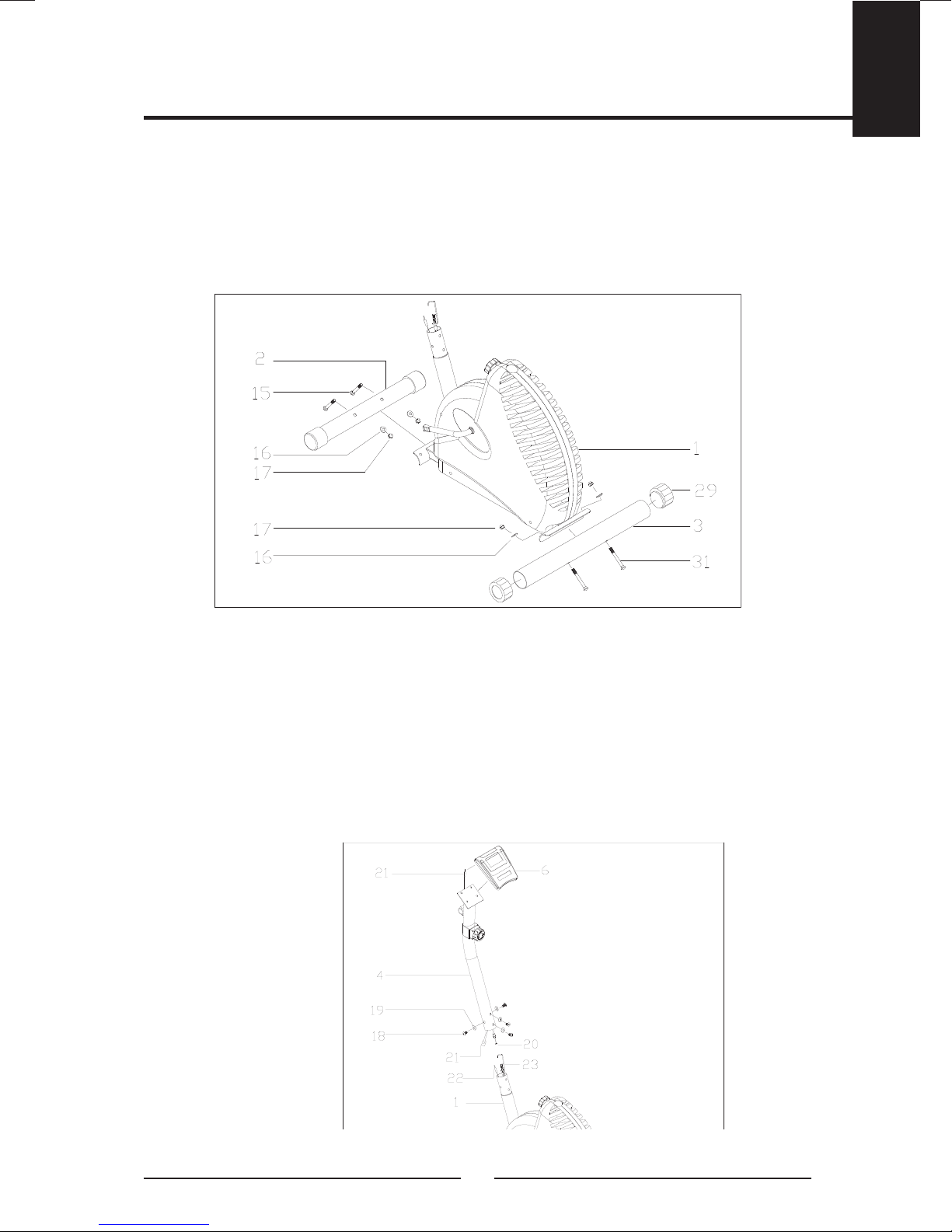
5. ASSEMBLY STEPS
STEP 1
Attach the Front Stabilizers (2) to the Main Frame (1),tighten 2 sets of M10*50mm
Carriage Bolt (15) Φ25 Curve Washer (16) and M10 Domed Nut (17).
Then, attach the Rear Stabilizer (3) to the Main Frame (1), tighten 2 sets of
M10*75mm Carriage Bolt (31) Φ25 Curve Washer (16) and M10 Domed Nut
(17).
ENGLISH
STEP 2
Take the Front Post (4) and join the Middle Computer Wire (21) with Lower
Computer Wire (22). Release the Tension Knob + Upper Tension Cable (20) from
the Front Post (4) and connect the Lower Tension Cable (23). Tighten with 3 sets
of M8*15Hex Bolt (18) and Φ22 Curve Washer (19).
Attention to let the Middle Compute Wire(21) comes out from the rear gap, then
connect the Upper Computer Wire (32). Then Slide the Computer (6) onto the
computer holder of Front Post (4).
9
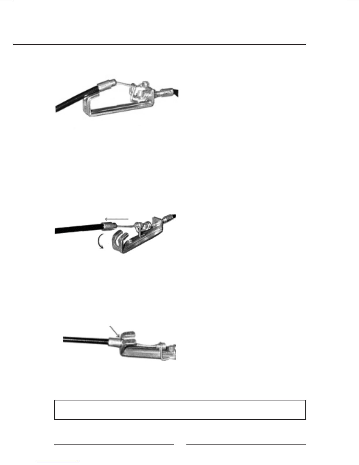
HOW TO CONNECT TENSION CONNECTOR
Slide the Cable wire from the Upper
Tension Connector in between the
opening on the wire holder on the
Lower Tension Connector.
Pull the Upper Tension Connector
backward and slide the wire through
the slot on the bracket.
NOTE: In able to hold the Computer Post while connecting the cables and
wires, extra help may be needed.
Drop down the Connector so
the tting sits rmly on top of the
bracket.
10
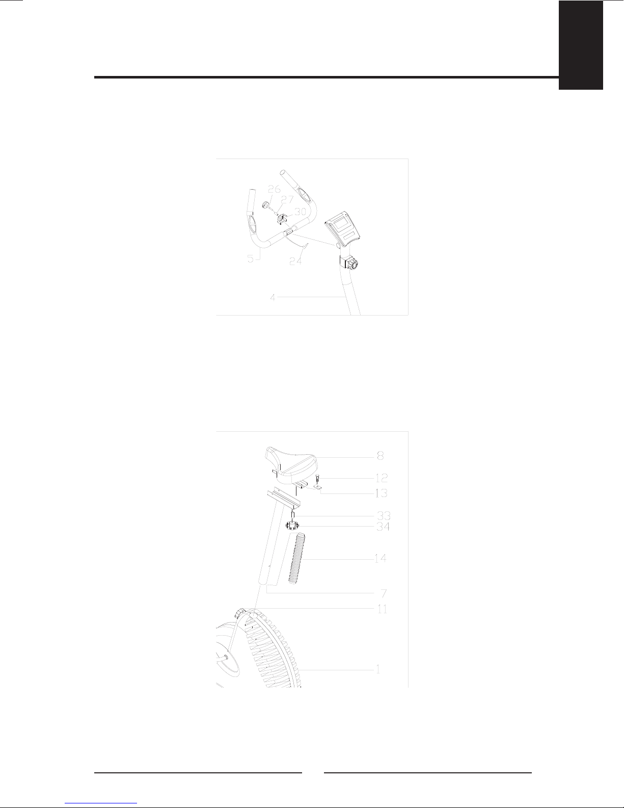
STEP 3
Fix the Handlebar (5) to the Front Post (4) and tighten with 1set of Hex Bolt M8*20
(27) on Clamp (30), then T Knob(26). Plug Hands Pulse Wire (24) to the computer
“pulse” hole.
STEP 4
Fix the Seat (8) to the Seat Post (7) using 3 setsΦ16 Flat Washer (12), Spring
Washer (13) and M8 Nylon Lock Nut (14), then insert into the Main Frame (1). Line
up the holes and secure the seat in position with the Adjustment Knob (11). The
Correct height for the seat can be adjusted after the bike is fully assembled.
ENGLISH
11
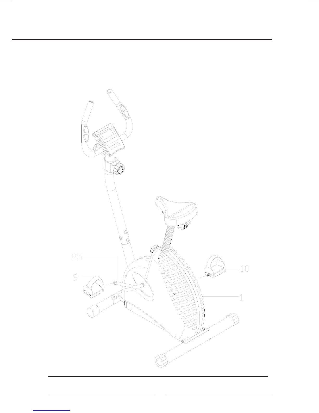
STEP 5
The Left and Right Pedal (9) &(10) are marked “L” and “R”.
Connect them to their appropriate Crank Arm (25). The right pedal is on the right
hand side of the cycle as you sit on it. Note that the right pedal should be threaded
on clockwise and the left pedal on counter-clockwise.
Recheck all bolts and nuts are tightened securely before use the machine.
12
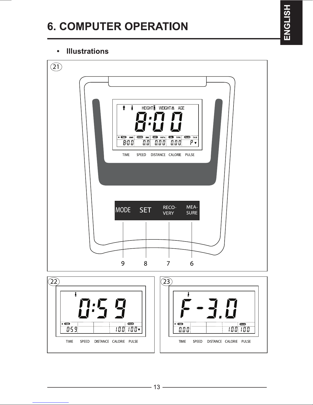
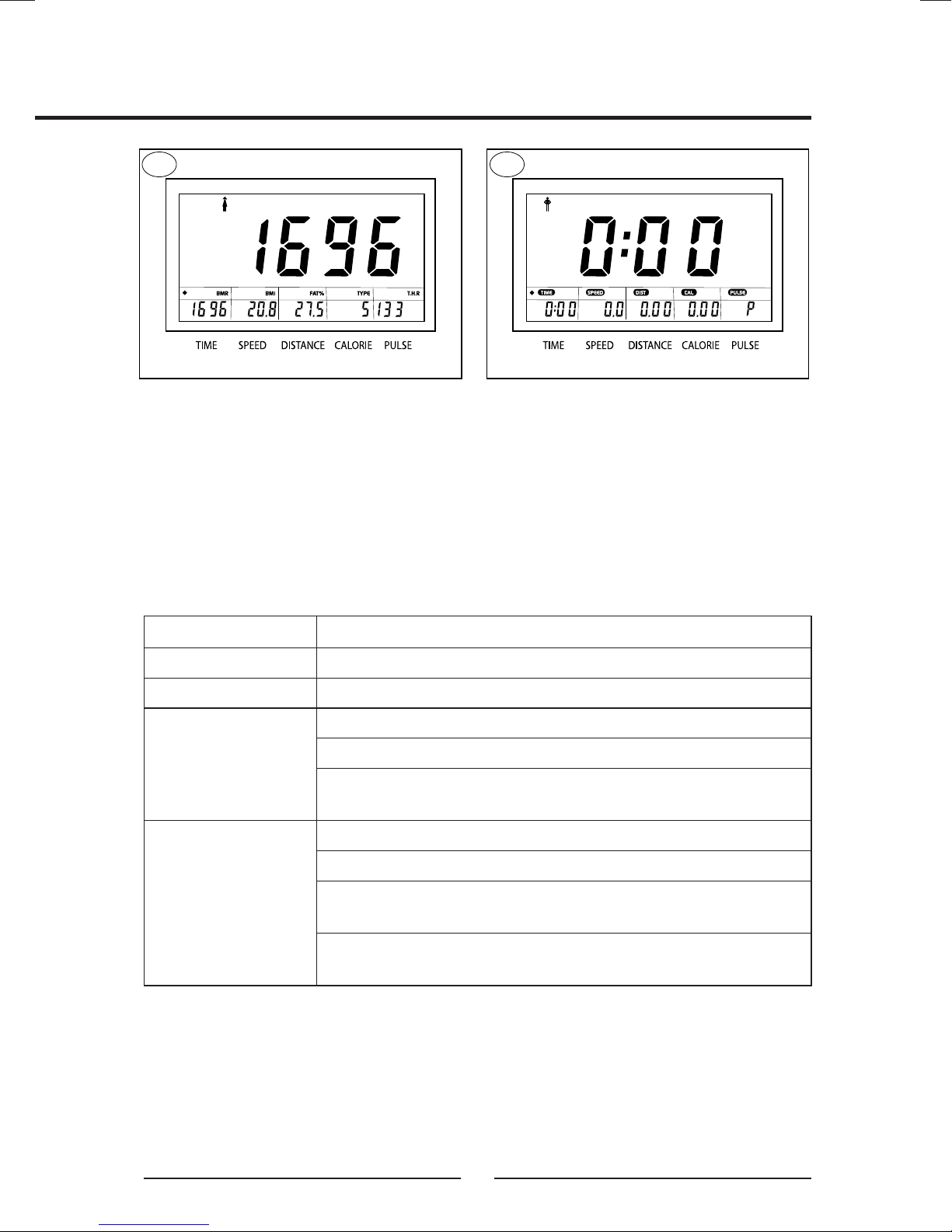
24 25
Your tness equipment comes equipped with a programmable computer, which
enables you to monitor the training progress and motivates the user to set and
achieve training goals. Prior to starting the training session, the user can preset a
target value for several functions, i.e. training time, distance or desired number of
burnt calories per session.
Switch On: Press one button or move the pedals
Switch Off: Automatically after 4 minutes.
BUTTON FUNCTION
MEASURE (6) • Select Body-Fat Mode
RECOVERY (7) • Select Recovery Pulse Mode
SET (8) • Adjustment
• Data Input
Note: By holding the button down the value of the
parameter will quickly increase
MODE (9) • Conrm
• Select Function
• Reset value :Hold the button for longer than 2
minutes
• Preset data/Enter value: Hold the button for 5
seconds
14
 Loading...