


Bulletin No. SPTS0130807
August 2007
9/10 Speed
Transmission
MODELS:
PS95-9A PSO100-10S
PS125-9A PSO125-10S
PS140-9A PSO140-10S
PSO125-9A PSO150-10S
PSO140-9A
PSO150-9A
Service Manual

9 SPEED TRANSMISSION
SAFETY FIRST
Carefully read this service |
manual |
General Safety Precautions |
before beginning any work |
on your |
|
Spicer transmission.
Throughout this literature, you will see symbols that warn of potential physical danger or product damage if the accompanying instructions aren't followed. Here are the symbols and their meanings.
This symbol indicates a potentially hazardous situation. If the instructions aren't followed, the result could be death or serious injury.
This symbol indicates that you must do some thing in order for the transmission to function properly. For example, you must use only one gasket underneath the shift tower. If it is eliminated, or more than one gasket is used, binding can occur. This would prevent proper shifting of the transmission and could damage the unit.
This symbol indicates that you must NOT do something in order to avoid damaging the transmission. For example, you must not use sealant underneath the shift tower. Using sealant underneath the tower will prevent proper interlock functioning and could damage the unit.
Be sure you understand all procedures and instructions in this manual before you begin working on your Spicer Transmission. If you have any questions, contact your Spicer® Transmission representative.
Use a hoist whenever lifting the transmission or shaft assemblies. Using a hoist can help prevent muscle strain or other possible injuries.
Always wear safety glasses when working on the transmissions to help prevent possible eye injury due to small parts (such as snap rings) or metal chips that may fly up unexpectedly during a teardown or rebuild.
Be careful when picking up gears or other sharp components. If you aren't careful, you could cut your hands. Consider wearing heavy cloth gloves or covering sharp objects with shop towels before picking them up.
When draining the transmission prior to working on it, be careful to let the unit cool down first.
Otherwise, hot transmission fluid could cause burns.
The information in this service manual was current at the time of publication.
This information is subject to change at any time without notice.
2
tech line 800-401-9866 |
www.ttcautomotive.com |
SECTION l |
GENERAL INFORMATION |
|
|
9-SPEED SPECIFICATIONS |
4 |
|
10 -SPEED SPECIFICATIONS |
4B |
|
TORQUE SPECIFICATIONS |
5 |
|
DRIVER INSTRUCTIONS |
6-7 |
SECTION II |
MAINTENANCE |
|
|
AIR LINE PIPING DIAGRAM |
8 |
|
FILTER REGULATOR |
9 |
|
LUBRICATION |
10 |
SECTION Ill |
GENERAL DISASSEMBLY |
11-12 |
SECTION IV |
SHIFT TOWER DISASSEMBLY |
13 |
SECTION V |
REMOTE CONTROL DISASSEMBLY |
14 |
SECTION VI |
RANGE CASE DISASSEMBLY |
|
|
CASE EXPLODED DRAWING |
15 |
|
GEARS EXPLODED DRAWING |
16 |
|
DISASSEMBLY |
17-21 |
SECTION VII |
MAIN CASE DISASSEMBLY |
|
|
CASE & SHIFT FORKS EXPLODED DRAWING |
22 |
|
CLUTCH HOUSING EXPLODED DRAWING |
23 |
|
MAIN CASE OPTILUBE EXPLODED DRAWING |
24 |
|
MAIN CASE GEARS EXPLODED DRAWING |
25 |
|
DISASSEMBLY |
26-28 |
SECTION VIII |
COUNTERSHAFT DISASSEMBLY & REASSEMBLY |
29 |
SECTION IX |
CLEANING & INSPECTION PROCEDURES |
30 |
SECTION X |
MAIN CASE REASSEMBLY |
31-33 |
SECTION XI |
RANGE CASE REASSEMBLY |
34-38 |
SECTION XII |
REMOTE CONTROL REASSEMBLY |
39 |
SECTION XIII |
SHIFT TOWER REASSEMBLY |
40 |
SECTION XIV |
TROUBLESHOOTING |
41-44 |
GENERAL INFORMATION
Section I
Gear Ratios
Gear |
Ratio |
O/D Ratio |
Rev |
14.30 |
13.95 |
1st |
13.95 |
10.40 |
2nd |
9.05 |
6.74 |
3rd |
6.51 |
4.85 |
4th |
4.77 |
3.55 |
5th |
3.55 |
2.65 |
6th |
2.55 |
1.89 |
7th |
1.83 |
1.37 |
8th |
1.34 |
1.00 |
9th |
1.00 |
0.74 |
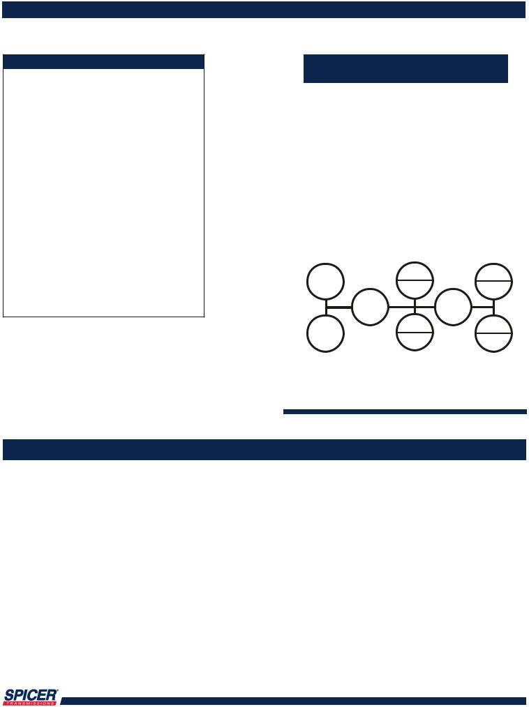
 Pro-Shift Nine Speeds
General Application Guidelines
On-Highway Use
GVW: |
PSO100: 80,000 Ibs. |
|
PSO125:110,OOOIbs. |
|
PSO140 & PSO150: 140,000 Ibs. |
HP Range: |
250 - 430 |
RPM Range: |
1,600 - 2,400 |
Engine Types: |
8-, 10-, and 14-liter diesel |
 Simple Shift Patterns
R |
6 |
8 |
|
2 |
4 |
||
|
|||
|
N |
N |
|
1 |
7 |
9 |
|
3 |
5 |
||
|
Model |
Weight * |
Clutch Housing |
Lube Capacity |
Overall Length |
PTO Speed (% of engin) |
|
PS95-9A |
|
|
|
|
|
|
|
|
|
|
|
||
PS125-9A |
625-635 lbs. |
Iron SAE |
18 pints |
28.96” |
|
|
284-288 (kgm) |
#1 or #2 |
(8.5 liters) |
(736 mm) |
61.5 |
||
PS140-9A |
||||||
|
|
|
|
|
||
|
|
|
|
|
|
|
PSO125-9A |
625-635 lbs. |
Iron SAE |
18 pints |
28.96” |
|
|
PSO140-9A |
|
|||||
284-288 (kgm) |
#1 or #2 |
(8.5 liters) |
(736 mm) |
82.6 |
||
PSO150-9A |
||||||
|
|
|
|
|
||
|
|
|
|
|
|
|
* weight includes clutch housing |
|
|
|
|
||
4
tech line 800-401-9866 |
www.ttcautomotive.com |


GENERAL INFORMATION
Section I
TORQUE SPECIFICATIONS FOR NUTS AND CAP SCREWS
|
|
|
|
Wrench Torque(ft. Ibs.) |
|
|
|
|
|
|
|||
Nom. Thread Size |
PART NAME |
NON-LOCKING TYPE |
LOCKING TYPE |
|||
(Dia.) |
|
|
|
|
(Bonded Nylon Patch) |
|
Inches |
mm |
|
Min. |
Max. |
Min. |
Max. |
|
|
|
|
|
|
|
.250 |
6 |
Cap Screw or Nut |
7 |
10 |
10 |
13 |
.312 |
|
|
13 |
17 |
20 |
24 |
.375 |
10 |
|
25 |
32 |
34 |
41 |
.438 |
|
|
40 |
50 |
52 |
62 |
|
12 |
|
|
|
60 |
80 |
.500 |
|
|
60 |
80 |
78 |
98 |
|
14 |
|
|
|
80 |
100 |
.562 |
|
|
90 |
115 |
112 |
137 |
.625 |
|
|
120 |
150 |
150 |
180 |
.750 |
|
|
200 |
250 |
240 |
290 |
1.250 |
|
Nut |
|
|
400 |
450 |
1.375 |
|
|
|
|
550 |
600 |
1.750 |
|
|
|
|
550 |
600 |
|
|
|
|
|
|
|
|
|
PTO Aperture Cover Cap Screws |
|
|
|
|
|
|
|
|
|
|
|
.375 |
|
Cap Screw |
10 |
15 |
16 |
24 |
.438 |
|
Cap Screw with Gasket 97-324-2 |
20 |
25 |
36 |
41 |
.438 |
|
Cap Screw with Gasket 22P22 |
20 |
25 |
29 |
34 |
|
|
|
|
|
|
|
5
tech line 800-401-9866 |
www.ttcautomotive.com |

GENERAL INFORMATION
Section I
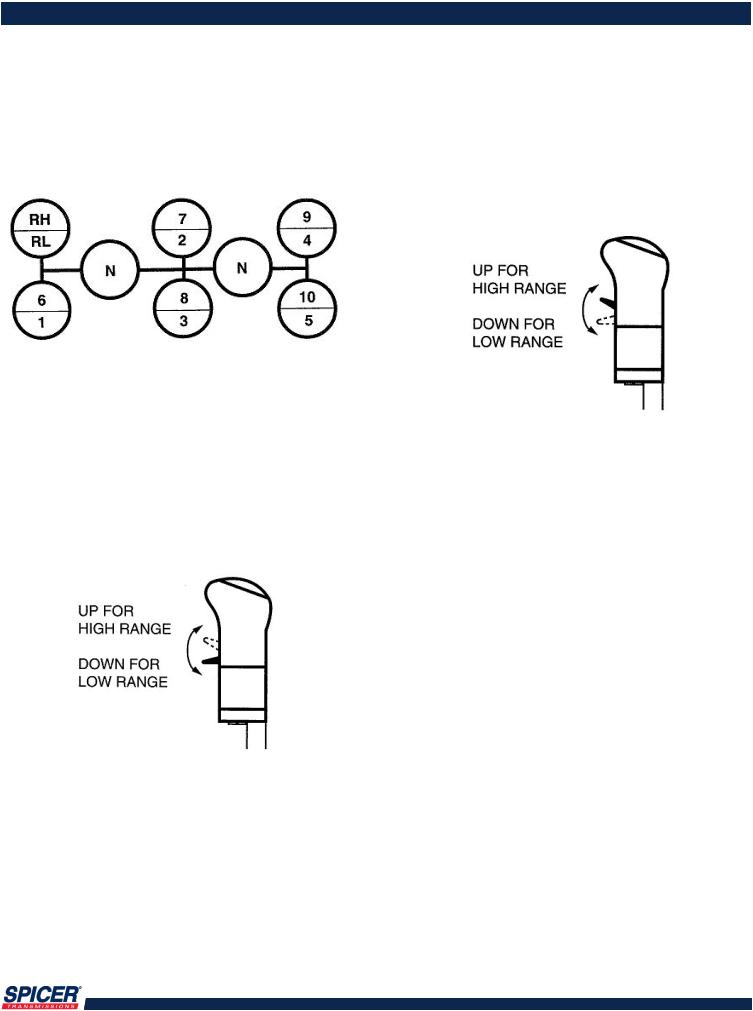
How to Shift the Spicer
PSO100-10S,PSO125-10S,
PSO140-10S & PSO150-10S
Transmissions
Starting Vehicle From a Stop
1.(A) With the gear shift lever in neutral,
(B)Clutch pedal depressed,
(C)And brakes set,
(D)Start the engine. Allow it to build to maximum air pressure.
2.(A) With the clutch pedal fully depressed to engage the clutch
brake (see "Clutch Brake"),
(B) Position the range selector to low range. Move the gear shift lever into 1st gear position.
3.(A) Release the tractor parking brakes and trailer parking brakes where applicable.
(B)Release the clutch pedal gradually to full position.
(C)Depress the throttle to start the vehicle moving.
4.(A) After attaining optima! speed in 1st gear,
(B)Depress the clutch pedal.
(C)Move the gear shift lever to neutral (See "Double Clutching: Upshifting’).
(D)Then move the gear shift lever to 2nd gear.
MODELS:
PS95-9A/PS125-9A/PS140-9A
PSO125-9A/PSO140-9A/PSO150-9A
5.(A) Continue the above procedures through 5th gear position.
6.(A) To continue upshifting (6th gear through 10th gear)
(B)Preselect high range on the range selector.
(C)Depress the clutch pedal.
(B) Move the |
gear |
shift lever from the 5th gear position |
to neutral |
(See |
"Double Clutching: Upshifting") |
(E) Then move the gear shift lever into 6th gear position.
7.(A) After attaining optimal speed in 6th gear,
(B)Depress the clutch pedal.
(C)Move the gear shift lever to neutral (see "Double Clutching: Upshifting")
(D)Then move the gear shift lever into 7th gear position.
8.(A) Continue these procedures for 8th - 10th gear positions.
Downshifting
Downshifting is actually just the reverse of upshifting (see "Double Clutching: Downshifting").
Clutch Brake
The clutch brake used with this unit is designed for stopping gear rotation so you can shift into 1st and reverse gears. The last one inch of clutch pedal travel activates the clutch brake. So on shifts other than 1st or reverse from a stop, only depress the clutch pedal enough to release the clutch. Depressing the pedal to the floorboard will activate the clutch brake and could cause gear hang-up or hard shifting.
When selecting a starting gear, if you have a butt-tooth condition, gradually release the clutch so the drive gear can rotate to align the gear clutching teeth to complete the shift.
6
tech line 800-401-9866 |
www.ttcautomotive.com |
GENERAL INFORMATION
Section I
How to Shift the Spicer
PSO100-10S,PSO125-10S,
PSO140-10S & PSO150-10S
Transmissions
Starting Vehicle From a Stop
1.(A) With the gear shift lever in neutral,
(B)Clutch pedal depressed,
(C)And brakes set,
(D)Start the engine. Allow it to build to maximum air pressure.
2.(A) With the clutch pedal fully depressed to engage the clutch
brake (see "Clutch Brake"),
(B) Position the range selector to low range. Move the gear shift lever into 1st gear position.
3.(A) Release the tractor parking brakes and trailer parking brakes where applicable.
(B)Release the clutch pedal gradually to full position.
(C)Depress the throttle to start the vehicle moving.
4.(A) After attaining optima! speed in 1st gear,
(B)Depress the clutch pedal.
(C)Move the gear shift lever to neutral (See "Double Clutching: Upshifting’).
(D)Then move the gear shift lever to 2nd gear.
MODELS:
PS95-9A/PS125-9A/PS140-9A
PSO125-9A/PSO140-9A/PSO150-9A
5.(A) Continue the above procedures through 5th gear position.
6.(A) To continue upshifting (6th gear through 10th gear)
(B)Preselect high range on the range selector.
(C)Depress the clutch pedal.
(B) Move the |
gear |
shift lever from the 5th gear position |
to neutral |
(See |
"Double Clutching: Upshifting") |
(E) Then move the gear shift lever into 6th gear position.
7.(A) After attaining optimal speed in 6th gear,
(B)Depress the clutch pedal.
(C)Move the gear shift lever to neutral (see "Double Clutching: Upshifting")
(D)Then move the gear shift lever into 7th gear position.
8.(A) Continue these procedures for 8th - 10th gear positions.
Downshifting
Downshifting is actually just the reverse of upshifting (see "Double Clutching: Downshifting").
Clutch Brake
The clutch brake used with this unit is designed for stopping gear rotation so you can shift into 1st and reverse gears. The last one inch of clutch pedal travel activates the clutch brake. So on shifts other than 1st or reverse from a stop, only depress the clutch pedal enough to release the clutch. Depressing the pedal to the floorboard will activate the clutch brake and could cause gear hang-up or hard shifting.
When selecting a starting gear, if you have a butt-tooth condition, gradually release the clutch so the drive gear can rotate to align the gear clutching teeth to complete the shift.
6
tech line 800-401-9866 |
www.ttcautomotive.com |

GENERAL INFORMATION
Section I
Double Clutching
Upshifting: The normal double clutching technique is suggested. When you want to shift, depress the clutch and move the lever to neutral. Engage the clutch and allow the engine RPM to drop so engine speed and driveline speed match. Depress the clutch and move the lever into gear. Engage the clutch and accelerate as conditions permit.
Downshifting: Downshifting is the reverse of upshifting. As the engine approaches the shift point (start the downshift approximately 50 -100 RPM above the shift point), depress the clutch and move the lever to neutral. Engage the clutch and raise the engine RPM until the engine and driveline speeds are equal (normally, governed speed). Depress the clutch, then shift into the next lower gear. Engage the clutch.
Skip Shifting
Experienced drivers sometimes want to skip some of the ratios. This is acceptable. However, you should do this only when operating conditions allow. Your speed, the load, and The road type and condition should be considered.
MODELS:
PS95-9A/PS125-9A/PS140-9A
PSO125-9A/PSO140-9A/PSO150-9A
Reminders
Double clutch when shifting. This will help
components match speed better during shifts and will help ensure proper engagement.
Downshift through all gear speeds when you are
slowing down. Chassis and trailer brake life can be increased by doing this.
Do not force the shift since this can cause damage
to clutch collars and clutching teeth. Use steady force on the shift lever to complete shifts.
Do not coast in neutral. The vehicle could lose RPM’s during coasting and you may not be able to shift back into the proper gear.
Do not downshift at road speeds that are too fast.
This could prevent proper gear engagement and could damage clutching teeth.
Do not tow vehicles without first pulling the axles
or disconnecting the driveshaft. If you tow the vehicle without doing this, you can damage drive train components because the system lubrication is inadequate when the vehicle is towed.
7
tech line 800-401-9866 |
www.ttcautomotive.com |
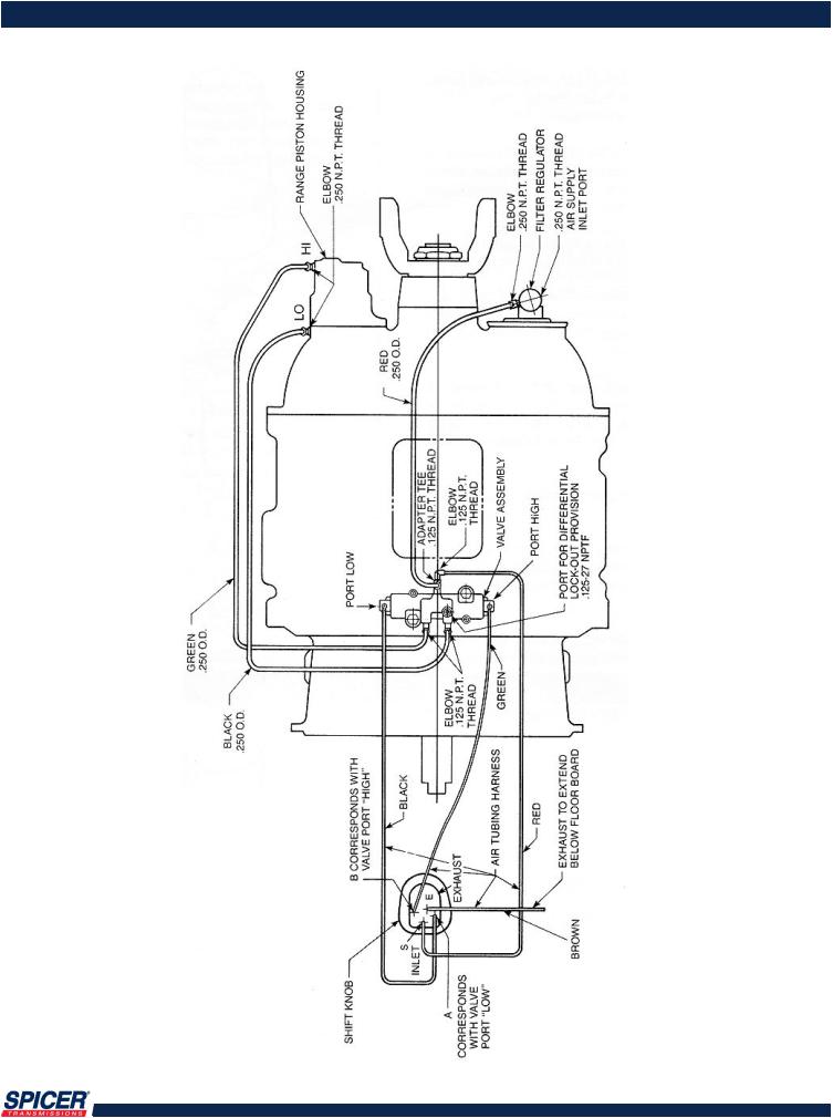
AIR LINE PIPING DIAGRAM
Maintenance
MODELS:
PS95-9A/PS125-9A/PS140-9A
PSO125-9A/PSO140-9A/PSO150-9A
8
tech line 800-401-9866 |
www.ttcautomotive.com |
MAINTENANCE
Section II
Filter Regulator
The 9 speed uses a filter regulator preset at 55-61lbs.
Use only petroleum-based solvents to clean parts. Other types of solvents could damage filter components and affect proper operation.
Blow air through the filter (inside and outside) to dislodge surface contaminants. Otherwise, these contaminants could affect proper filter operation and lead to equipment damage.
Do not disassemble the regulator section (9): it is not field-repairable. If it is damaged, replace it.
1. Clean or replace the filter element (7) every 6-12 months, or whenever slow shifting is encountered. The element should be replaced after three cleanings. If regulator malfunction is indicated, replace the entire unit.
2.To service the filter section, shut off the air pressure. Unscrew the bowl (1) and remove the O-ring (2). Unscrew the stud (4). Remove the louver (5), upper gasket (6), element (7),
and lower gasket (8) from the stud. Do not disassemble the regulator section (9).
3.After cleaning, inspect the parts carefully. Replace any damaged parts.
4.Reassemble the unit by first installing the element (7) on the stud (4), so that the large end of the internal taper (thinnest wall section) is toward the hex on the stud. Torque the stud to 5 - 10 Ibs. inch.
5.Apply a wipe coat of Dow Corning DC7 Silicone Grease (or equivalent) to the O- ring (2) seating surfaces on the regulator (9) and bowl (1). Apply a light, even coat of Molykote "G" (or equivalent) to the bowl threads. Torque the bowl to 5 -10 Ibs. inch. If the drain valve (3) was removed, reinstall it and torque it to 10-15 Ibs. Inch.
MODELS:
PS95-9A/PS125-9A/PS140-9A
PSO125-9A/PSO140-9A/PSO150-9A
9
tech line 800-401-9866 |
www.ttcautomotive.com |

MAINTENANCE
Section II
Lubrication
CAUTION: To ensure proper lubrication and
operating temperatures in this unit, the proper
lubricants must be used. Correct oil levels must be maintained. Spicer recommends using only lubricants produced by reputable, well-known suppliers. If you want to use a lubricant not specified below, please contact your local truck dealer to determine whether the lubricant is suitable for your purposes.
Recommended Lubricants
The lubricants listed below are recommended for use in all Spicer mechanical transmissions, auxiliaries, and transfer cases.
Oil Changes
Many factors influence oil change periods. Changes should be scheduled at three years or 250,000 miles with synthetic engine oil for normal over-the-highway operations. Offhighway use usually requires an oil change every 1,000 hours. The oil level in the transmission should be checked every 5,000 miles (8,045 km) on-highway, or every 40 hours in off-highway operation. When it is necessary to add oil, Spicer recommends that types and brands of oil not be mixed. The correct oil level in this transmission is established by the filler plug opening.
MODELS:
PS95-9A/PS125-9A/PS140-9A
PSO125-9A/PSO140-9A/PSO150-9A
Refill
First, remove all dirt around the filler plug. Then refill the transmission with new oil. Use the grade recommended for the existing season and prevailing service. The lubricant should be level with the oil fill plug located on the left side of the transmission case.
Overfilling:
CAUTION: Do not overfill the transmission. This usually results in oil breakdown due to excessive heat and aeration from the churning action of the gears. Early breakdown of the oil will result in heavy varnish and sludge deposits that plug up oil ports and build up on splines and bearings
Temperature |
Grade |
Type |
All |
CD 50 |
Synthetic engine oil meeting MIL-L-2104 D |
|
|
or MIL-L-46152 B, API-SF or API-CD |
Oil Cooler |
|
|
See standard application requirements. |
|
|
10
tech line 800-401-9866 |
www.ttcautomotive.com |

GENERAL DISASSEMBLY
Section III
Important Procedure
To locate and correct unit power or auxiliary transmission troubles, a systematic procedure should be followed.
Road test whenever possible. Mechanics usually get secondor third-hand reports of trouble experienced with the unit. These reports do not always accurately describe the actual conditions. Sometimes symptoms seem to indicate trouble in the transmission, while actually the problem is with the axle, driveshaft, universal joints, engine or clutch. This is especially true of noise complaints. Therefore, before removing the transmission or related components to locate trouble, road test to check the possibility of trouble in other closely associated units. Road testing is most effective when the mechanic drives the vehicle. However, riding with the driver can be very informative.
Check Functioning
Prior to Disassembly
If a remote control is used, a careful check of the remote and connecting linkages (and their adjustment) must be made. The remote unit must be in good working order if the transmission is expected to shift satisfactorily.
Many times, the answer to the trouble is apparent when the unit is inspected prior to disassembly. But this evidence is often lost when the parts are separated. If possible, check the unit prior to disassembly. Bear in mind that a careful inspection of the unit should be made as each disassembly step is performed.
MODELS:
PS95-9A/PS125-9A/PS140-9A
PSO125-9A/PSO140-9A/PSO150-9A
Inspect Thoroughly
During Disassembly
It is poor practice to disassemble a unit or the complete transmission as quickly as possible without examining the parts. The mechanic may completely disassemble a unit and fail to find the cause of the trouble, unless he examines the parts. After the transmission is disassembled, check the lubricant for foreign particles. This is a source of trouble often overlooked during the disassembly.
Repair or Replace Worn Parts
Many times the parts or critical adjustments causing the trouble are not replaced or corrected because the mechanic only inspects and replaces parts that have failed completely. All pieces should be carefully examined because broken parts are often just the result not the cause of the problem. All parts that are broken or worn and no longer meet specifications should be replaced.
Also, parts that are worn to the extent that they do not have a long service life remaining should be replaced. Replacing these parts now will avoid another teardown on the unit in the near future. Also at this time, make the recommended changes or modifications to bring the transmission up to date and increase the service life of the unit.
11
tech line 800-401-9866 |
www.ttcautomotive.com |
GENERAL DISASSEMBLY
Section III
 Read this section before starting the detailed disassembly procedures. Follow procedures closely to ensure proper transmission operation.
Rebuild Facilities
A suitable holding fixture or overhaul stand with a hole for the input shaft is desirable.
For easier working conditions, table height should be 28 - 30 inches. A light chain hoist should be used to handle the mainshaft and countershafts during removal and reassembly procedures.
Cleanliness
Transmissions should be steam cleaned prior to disassembly. Seal all openings before steam cleaning to prevent entry of dirt and water which can damage serviceable parts.
Dirt is abrasive and will cause premature wear of bearings and other parts. Spicer suggests that mechanics have a wash tank available to clean parts just prior to reassembly.
MODELS:
PS95-9A/PS125-9A/PS140-9A
PSO125-9A/PSO140-9A/PSO150-9A
Do not hammer on end yokes and flanges to remove or install them. It is not only destructive to the yoke or the flange itself, but can also cause serious
internal transmission damage. Hammering destroys or mutilates the pilot diameters and warps or bends the flange. Hammering on end yokes will close-in the bearing bores or misalign yoke lugs. This will result in early failures of journal needle bearings.
Serious damage can be done internally to bearings, thrust faces and washers by hammering on external parts. In most designs, when the yoke/flange locknuts are tightened and secure, the internal bearings and gears are in proper location. When the yoke/flange is driven on the shaft, however, two conditions can exist.
(A)If the bearing fit is tight on the shaft, usually the bearings will brinell as they must absorb the pounding force.
(B)If the bearing fit is loose, the shaft will keep moving inward until it is stopped by the internal parts such as the pilot bearing thrust washers.
These conditions must be prevented.
Power Take-Offs
Refer to your owner's manual, installation procedures, and safety precaution when installing any PTO on your transmission.
Bearings
When a transmission is removed at relatively low mileage, bearings should be removed with pullers designed for this purpose. Wrap the bearings to keep out dirt. Clean, inspect, and lubricate all bearings just prior to reassembly. If accumulated mileage is over 150,000 miles, we suggest that all bearings be replaced. If bearings are worn or damaged, always replace them regardless of mileage.
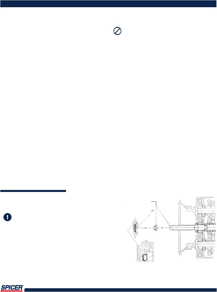
Front Bearing Retainer & Seal 
When installing the front bearing retainer and seal in the transmission, use the red plastic sleeve to prevent serious damage to the oil seal. Failure to use the seal sleeve will void the seal warranty.
Push sleeve over end of shaft install bearing cap assembly
After red sleeve is in place install seal dry
Hydrodynamic Lip
Seal must be installed so that Hydrodynamic Lip faces toward inside of transmission.
Remove seal cardboard shipping tube or plastic installation sleeve just prior installing bearing cap assembly to transmission.
12
tech line 800-401-9866 |
www.ttcautomotive.com |
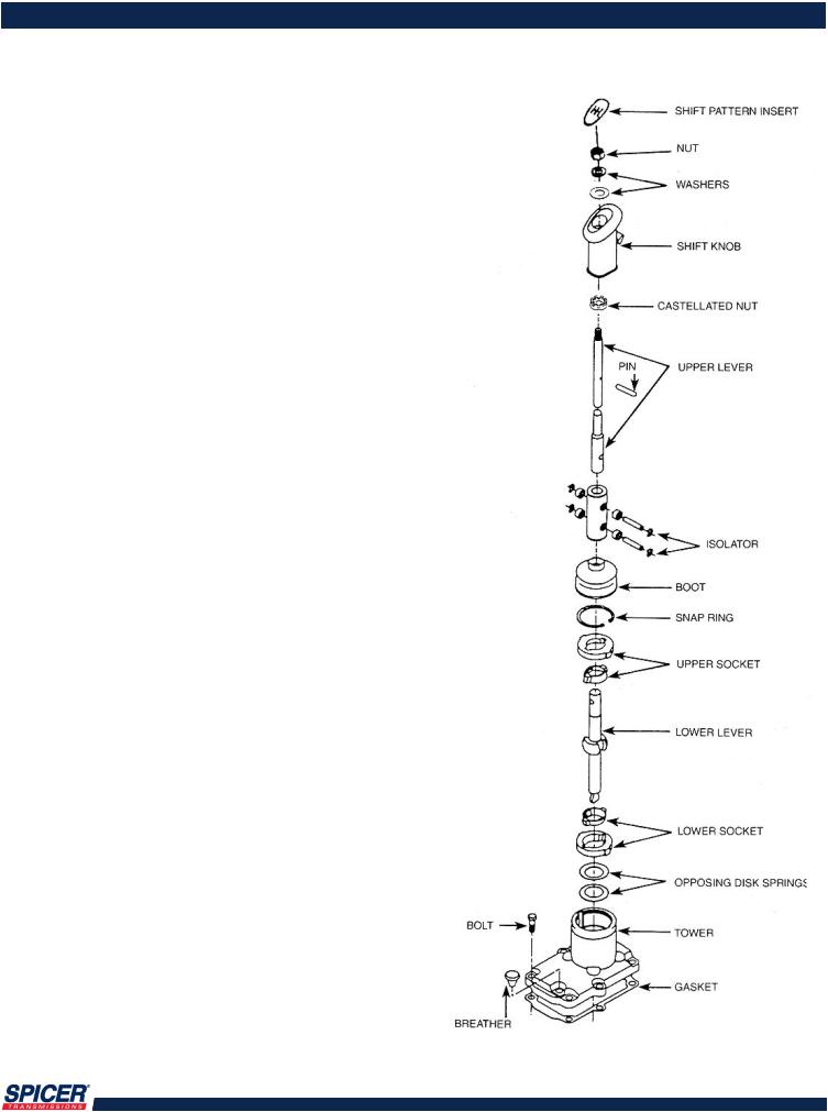
SHIFT TOWER DISASSEMBLY
Section IV
1.Cut the tie-down straps and lift the boot off the lever.
2.Holding the lever in a vise,. Remove the tower snap ring.
3.Pull the lever, the upper and lower plastic sockets, and the two opposing springs from the tower.
MODELS:
PS95-9A/PS125-9A/PS140-9A
PSO125-9A/PSO140-9A/PSO150-9A
13
tech line 800-401-9866 |
www.ttcautomotive.com |
 Loading...