

Page 1
Water heaters Workshop Manual
DBW 160
DBW 230(2020)
DBW 300
DBW 350
Status: 07/2010
Visit www.butlertechnik.com for more technical information and downloads.
www.butlertechnik.com
Page 2

Visit www.butlertechnik.com for more technical information and downloads.
www.butlertechnik.com
Page 3
DBW 160 / 230 (2020) / 300 / 350 Contents
2
Contents
1 Introduction
1.1 Contents and purpose .......................................................................................................................... 101
1.2 Applicability of the manual.... ... ... ... ....................................................................................................... 101
1.3 Meaning of accentuations..................................................................................................................... 101
1.4 Further documentation to be used........................................................................................................ 101
1.5 Safety information and regulations....................................................................................................... 101
1.5.1 General safety regulations......................................................................................................... 101
1.6 Legal requirements regarding the installation.................... ... ... .... ... ... ... ................................................ 102
1.7 Suggestions for improvements and modifications ................................................................................ 103
2 General Description
2.1 Combustion air fan................................................................................................................................ 204
2.2 Motor..................................................................................................................................................... 204
2.3 Fuel pump............................................................................................................................................. 204
2.3.1 Nozzle-block preheater.............................................................................................................. 205
2.4 Heat exchanger .................................................................................................................................... 205
2.5 Combustion chamber............................................................................................................................ 206
2.6 Control unit ........................................................................................................................................... 206
2.7 Flame sensor........................................................................................................................................ 207
2.8 Electronic ignition unit with ignition electrodes ..................................................................................... 207
2.9 Temperature limiter /thermal fuse......................................................................................................... 208
2.10 Control thermostat................................................................................................................................ 208
2.11 Fan thermostat...................................................................................................................................... 209
2.12 Circulation pump................................................................................................................................... 209
3 Function Description
3.1 General................................................................................................................................................. 301
3.2 Operation.............................................................................................................................................. 301
3.2.1 Activation................................................................................................................................... 301
3.2.2 Heating operation...................................................................................................................... 301
3.2.3 Deactivation............................................................................................................................... 301
3.2.4 Malfunction cut-out................. ... ... ... ... .... ... ... ............................................................................. 301
4 Technical data
Electrical components..................................................................................................................................... 401
Fuel .............................................................................................................................................................. 401
Visit www.butlertechnik.com for more technical information and downloads.
www.butlertechnik.com
Page 4
Contents DBW 160 / 230 (2020) / 300 / 350
3
5 Troubleshooting
5.1 General................................................................................................................................................ 501
5.2 General fault symptoms....................................................................................................................... 501
5.3 Troubleshooting – quick diagnostic...................................................................................................... 503
5.4 Fault symptoms........................ .... ........................................................................................................ 504
5.4.1 Heater does not start when being switched on......................................................................... 504
5.4.2 Heater repeatedly switches into malfunction mode approx. 30 s after bein g switched on ....... 505
5.4.3 Heater requires several attempts to start ................................................................................. 506
5.4.4 Heater turns off by itself during operation................................................................................. 506
5.4.5 Heater creates black smoke..................................................................................................... 507
5.4.6 Heater creates white smoke................................ ..................................................................... 508
5.4.7 Heater cannot be switched off.................................................................................................. 508
6 Function Checks
6.1 General................................................................................................................................................ 601
6.2 Settings................................................................................................................................................ 601
6.2.1 Adjusting CO
2
contents ............................................................................................................ 601
6.3 Checks of individual components ........................................................................................................ 602
6.3.1 Check of flame-sensor resistance ............................................................................................ 602
6.3.2 Check and adjustment of ignition electrodes............................................................................ 603
6.3.3 Check of electronic ignition unit................................................................................................ 603
6.3.4 Check of fuel pump................................................................................................................... 603
6.3.5 Check of burner motor.............................................................................................................. 604
6.3.6 Check of solenoid valve............................................................................................................ 604
6.3.7 Check of nozzle-block preheater.............................................................................................. 604
7 Wiring diagrams
7.1 General................................................................................................................................................ 701
8 Service and Maintenance
8.1 General................................................................................................................................................ 801
8.2 Heater servicing................................................................................................................................... 801
8.3 Vehicle servicing.......................................... ... ..................................................................................... 801
8.4 Heater test run..................................................................................................................................... 801
8.5 Maintenance work................................................................................................................................ 801
8.5.1 Swinging the burner head open and closed ............................................................................. 802
8.6 Visual inspections /
installation specifications 803
8.6.1 Connection to the vehicle's cooling system.............................................................................. 803
8.6.2 Connection to the vehicle's fuel system.................................................................................... 803
8.6.3 Combustion air supply.............................................................................................................. 805
8.6.4 Exhaust pipe............................................................................................................................. 805
Visit www.butlertechnik.com for more technical information and downloads.
www.butlertechnik.com
Page 5
DBW 160 / 230 (2020) / 300 / 350 Contents
4
8.7 Removal and installation....................................................................................................................... 806
8.7.1 Heater, removal and installation................................................................................................ 806
8.7.2 Replacing the temperature limiter.............................................................................................. 806
8.7.3 Replacing the control thermostat............................................................................................... 806
8.7.4 Replacing the fan thermostat..................................................................................................... 806
8.7.5 Replacing the thermal fuse........................................................................................................ 806
8.7.6 Replacing the burner head........................................................................................................ 806
8.7.7 Replacing the electronic ignition unit......................................................................................... 806
8.7.8 Replacing the flame sensor....................................................................................................... 806
8.7.9 Replacing the combustion chamber.......................................................................................... 807
8.8 Start-up................................................................................................................................................. 808
8.8.1 Bleeding the coolant circuit........................................................................................................ 808
8.8.2 Bleeding the fuel-supply system................................................................................................ 808
9Repair
9.1 General................................................................................................................................................. 901
9.1.1 Measures on components in disassembled condition............................................................... 902
9.1.2 Carrying out modifications......................................................................................................... 902
9.2 Disassembly and assembly.................................................................................................................. 907
9.2.1 Replacing the temperature limiter.............................................................................................. 907
9.2.2 Replacing the control thermostat............................................................................................... 907
9.2.3 Replacing the fan thermostat..................................................................................................... 909
9.2.4 Replacing the thermal fuse........................................................................................................ 909
9.2.5 Replacing the control unit.......................................................................................................... 909
9.2.6 Replacing the burner head........................................................................................................ 909
9.2.7 Replacing the motor .................................................................................................................. 911
9.2.8 Replacing the high-pressure nozzle.......................................................................................... 912
9.2.9 Replacing the nozzle-block preheater....................................................................................... 912
9.2.10 Replacing the electronic ignition unit......................................................................................... 912
9.2.11 Replacing the flame sensor....................................................................................................... 912
9.2.12 Replacing the ignition electrodes............................................................................................... 912
9.2.13 Replacing the fuel pump............................................................................................................ 914
9.2.14 Replacing the solenoid valve..................................................................................................... 914
9.2.15 Replacing the combustion chamber.......................................................................................... 914
9.2.16 Thermostat of the nozzle-block preheater................................................................................. 914
9.2.17 Replacing the heat exchanger................................................................................................... 916
9.2.18 Replacing the nozzle block........................................................................................................ 917
9.2.19 Replacing the combustion air fan.............................................................................................. 917
10 Packaging / Storage and Shipping
10.1 General............................................................................................................................................... 1001
A Appendix
Regular maintenance of heater....................................................................................................................... A-2
Visit www.butlertechnik.com for more technical information and downloads.
www.butlertechnik.com
Page 6
List of Figures DBW 160 / 230 (2020) / 300 / 350
5
List of Figures
301 Function sequence (heaters with control unit 1553)...................................................................................... 302
501 General fault symptoms ............................................... .................................................................................. 501
701 Au tomatic wiring diagram, DBW 160 with control unit 1553 and switch, system variants and pin allocation 702
702 Automatic wiring diagram, DBW 230/300 with control unit 1553, 24 volts..................................................... 704
703 Automatic wiring diagram, DBW 300/350 with control unit 1553, 24 volts..................................................... 706
704 Application ex ample for DBW 160/230/300, 12 and 24 volts, operation with timer and battery switch.......... 708
801 Swinging the burner head open and closed................................................................................................... 802
802 Example of heater installation in a bus .......................................................................................................... 804
901 Replacement of temperature limiter, control thermostat, fan thermostat and thermal fuse ........................... 908
902 Replacement of the control unit..................................................................................................................... 910
903 Replacement of the burner head.................................................................................................................... 910
904 Replacement of the motor.............................................................................................................................. 911
905 Replacement of nozzle block, nozzle-block preheater, high-pressure nozzle and flame sensor................... 913
906 Replacement of the thermostat of the nozzle-block preheater....................................................................... 915
907 Replacement of the solenoid valve................................................................................................................ 915
908 Replacement of the combustion chamber and the heat exchanger............................................................... 916
909 Replacement of the combustion air fan.......................................................................................................... 918
Visit www.butlertechnik.com for more technical information and downloads.
www.butlertechnik.com
Page 7
DBW 160 / 230 (2020) / 300 / 350 1Introduction
101
1Introduction
1.1 Contents and purpose
This workshop manual serves to support trained personnel in the repair of coolant heaters DBW 160/230/300 /350.
The heater may only be operated with the specified fuel
(diesel) and only with the type of electrical connection
specified for the respective model.
1.2 Applicability of the manual
The manual is applicable for the heaters listed on the title
page. The heaters mainly differ with regard to their technical data (see Section 4).
1.3 Meaning of the warning and safety
notices
In this manual, the signal words DANGER, CAUTION and
NOTE have the following meanings:
DANGER
This heading is used when incorrect compliance or noncompliance with instructions or procedures may result in
injuries or lethal accidents.
CAUTION
This heading is used when incorrect compliance or non-
compliance with instructions or procedures may result in
damage to components.
NOTE
This headline is used to indicate particularly useful or
special information.
1.4 Further documentation to be used
This workshop manual contains all information and instructions required for the repair of coolant heaters DBW
160/230/300/350.
The use of additional documentation is normally not required.
If required, the installation instructions and the operating
instructions can be used in addition.
1.5 Safety information and
regulations
As a rule, the applicable general regulations and instructions concerning accident prevention and work safety
must be observed.
"General safety regulations" beyond the scope of these
regulations are listed in the following.
The special safety regulations of importance for this
manual are indicated in the relevant sections or process
descriptions in the form of signal words (warnings, cautions, notes).
1.5.1 General safety regulations
For the heaters DBW 160/230/300/350, type approvals
according to EC directives 72/245/EEC (EMC) and 2001/
56/EC (heater systems) have been granted, with the EC
approval number:
e1*2001/56*0006xx
For installation, primarily the provisions of Annex VII to di-
rective 2001/56/EC must be observed.
CAUTION
Non-compliance with the installation instructions and the
notes contained will lead to exclusion of liability by Spheros. The same applies to repairs not carried out by experts
or without the use of genuine spare parts. This will result
in the invalidation of the General Build-Type Approval of
the heater and hence the General Certification (German
'ABE').
The year the heater was initially commissioned must
be permanently marked on the type label
by removing the relevant year.
The heaters are approved for heating the vehicle engine
and the passenger compartment. When the heater is used
in vehicles not subject to the StVZO [German road-traffic
licensing regulations] (e.g. ships), locally applicable regulations must be complied with.
The heater may only be installed in vehicles or in independent heating systems with a minimum coolant volume
of 10 litres.
Visit www.butlertechnik.com for more technical information and downloads.
www.butlertechnik.com
Page 8
1Introduction DBW 160 / 230 (2020) / 300 / 350
102
The heater may not be installed in the driver's or passenger's compartments of vehicles. If the heater is nevertheless installed in such a compartment, the installation case
must be tightly sealed towards the vehicle interior. From
the outside, the installation case must be sufficiently
vented so that a maximum temperature of 85 °C in the installation case is not exceeded. If this temperature is exceeded, malfunctions may occur.
DANGER
Because of danger of poisoning and suffocation, the
heater must not, not even with a timer, be operated in
enclosed rooms such as garages or workshops
without exhaust-gas extraction systems.
Because of explosion hazard, the heater must be
switched off at filling stations and filling systems.
CAUTION
Wherever flammable fumes or dust can form (e.g.
near fuel, carbon, wood-dust, cereal storage sites or
similar), the heater must be switched off due to explosion hazard.
The heater may not be operated in the vicinity of flammable materials, such as dry grass, leaves, cardboard
boxes, paper etc.
In the vicinity of the control unit, an ambient temperature
of 110°C (storage temperature) must not be exceeded
(e.g. when paint work is carried out on the vehicle).
If the specified temperature is exceeded, permanent
damage to the electronics may occur. When checking the
coolant level, proceed according to the vehicle manufac-
turer's instructions. The coolant in the heating circuit must
contain at least 10% of a brand-name anti-freeze agent.
Additives in the heating circuit may not be aggressive
against metals, plastics and rubber and may not cause
any deposits.
The opening pressure in the vehicle cooling syst em usually indicated on the radiator cap – must range
between 0.4 and 2.0 bar allowable working pressure (also
applies to separate heating circuits).
1.6 Legal requirements regarding the
installation
For installation, primarily the provisions of Annex VII to directive ECE R122 must be observed.
NOTE:
The provisions of these directives are binding in the
area of application of the ECE directive and should
also be observed in countries without specific regula-
tions!
(Excerpt from directive ECE R122, Appendix VII)
7.1 A clearly visible operation indicator in the operator's
field of vision must inform about the heater being switched
on or off.
Regulations regarding the installation in the vehicle
5.3.1 Area of application
5.3.1.1 As stipulated in Section 5.3.1.2, combustion
heaters must be installed according to the provisions of
Section 5.3.
5.3.1.2 In class-O vehicles with heaters for liquid fuel, it is
assumed that they comply with the pr ovisions of Section
5.3.
5.3.2 Positioning of the heater
5.3.2.1 Parts of the vehicle body and other components
in the vicinity of the heater must be protected from excessive heating and possible fuel or oil-induced soiling.
5.3.2.2 Even in the event of overheating, no fire hazard
may be caused by the combustion heater. This provision
is considered to be complied with if, during installation, relevant clearance to all components is maintained, sufficient ventilation is provided for or fire-resistant materials
or heat shields have been used.
5.3.2.3 In class-M2 and M3 vehicles, the combustion
burner may not be located in the passenger compartment.
Its installation in the passenger compartment is, however,
permissible when it is located in a properly se aled casing
which also complies with the provisions of Section 5.3.2.2.
5.3.2.4 The label named in Appendix 7, Section 1.4 or a
duplicate must be positioned to allow for easy reading
when the heater is installed in the vehicle.
5.3.2.5 The heater must be installed in a location where
the risk of injuring persons and damaging items carried is
as small as possible.
5.3.3 Fuel supply
5.3.3.1 The fuel-filler neck may not be located in the passenger compartment and must be equipped with a tigh tlysealing cap which prevents fuel from escaping.
5.3.3.2 In heaters for liquid fuel, where the fuel supply is
separated from the vehicle's fuel supply, the type of fuel
and the filler neck must be clearly marked.
5.3.3.3 On the filler neck, a note must be visible, saying
that the heater must be switched off before refuelling it. A
corresponding instruction must also be included in the
Visit www.butlertechnik.com for more technical information and downloads.
www.butlertechnik.com
Page 9

DBW 160 / 230 (2020) / 300 / 350 1Introduction
103
manufacturer's operating manual.
5.3.4 Exhaust system
5.3.4.1 The exhaust outlet must be positioned so that no
exhaust fumes can get into the vehicle's interior via
venting devices, hot-air inlets or window openings.
5.3.5 Combustion air inlet
5.3.5.1 The air for the heater's combustion chamber must
not be drawn in from the vehicle's passenger compartment.
5.3.5.2 The air inlet must be protected and positioned in
a way that it cannot be blocked by garbage or luggage.
5.3.6 Heating air inlet
5.3.6.1 The combustion air supply may consist of ambient
air or circulating air and must be drawn in from a clean
area which can presumably not be contamina ted by
exhaust gas from the engine, the combustion heater or
another source in the vehicle.
5.3.6.2 The inlet opening must be protected by grilles or
other suitable means.
5.3.7 Heating air outlet
5.3.7.1 Hot air pipes in the vehicle must be protected and
positioned so touching them will not result in injuries or
damage.
5.3.7.2 The air outlet must be protected and positioned in
a way that it cannot be blocked by garbage or luggage.
5.3.8 Automatic control of the heating system
5.3.8.1 When the engine stalls, the heating system must
automatically be switched off and the fuel supply interrupt-
ed within five seconds. If a manually operated control
device has already been activated, the heating system
can remain in operation.
CAUTION:
Non-compliance with the installation instruction s and
the notes contained will lead to exclusion of liability
by Spheros. The same applies to repairs not carrie d
out by experts or without the use of original spare
parts. This results in the invalidation of the heater's
type approval and hence the ECE type approval.
Installation instructions for separate fuel tanks with regard
to the fuel supply of coolant heaters in vehicles:
• In busses, the installation in the passenger's or driv-
er's compartment is not permissible.
• In no vehicle may the fuel-filler neck be located in the
passenger's or driver's compartment.
• The fuel tanks must either be equipped with a vent ilat-
ed cap or any other type of ventilation (vent line).
Only caps in compliance with DIN 73400 may be used.
1.7 Suggestions for improvements and
modifications
Please address any complaints, improvements or suggestions for correction of this technical manual to:
Spheros GmbH
Friedrichshafener Straße 9 - 11
82205 Gilching
Phone: +49 (0) 8105 7721-201
Fax: +49 (0) 8105 7721-199
Visit www.butlertechnik.com for more technical information and downloads.
www.butlertechnik.com
Page 10
1Introduction DBW 160 / 230 (2020) / 300 / 350
104
Notes
Visit www.butlertechnik.com for more technical information and downloads.
www.butlertechnik.com
Page 11
DBW 160 / 230 (2020) / 300 / 350 2 General Description
201
2 General Description
The Spheros DBW 160, 230, 300 and 350 coolant heaters
supplement the vehicle's heating system
– to heat the passenger compartment
– to defrost the windows, and
– to preheat liquid-cooled engines.
The coolant heater functions independently of the vehicle
engine and is connected to the cooling system, fuel
system and electric system.
The heater is designed for heat transfer a nd is contr olled
by a temperature sensor. It's operation is intermittent.
The heaters of the type DBW 160, 230, 300 and 350 com-
prise the following main components:
– combustion air fan
– fuel pump
– heat exchanger
– combustion chamber
– electronic ignition unit with ignition electrodes
Some heater variants are equipped with a nozzle- blo ck
preheater.
The heater is controlled by
– a control unit
– a flame sensor
integrated in the device.
The control units are fitted laterally at the rear or on the
top, depending on the heater variant.
The heater may comprise
– a temperature limiter
– a thermal fuse
– a fan thermostat
depending on variant.
An external circulation pump is installed in the vehicle.
Visit www.butlertechnik.com for more technical information and downloads.
www.butlertechnik.com
Page 12
2 General Description DBW 160 / 230 (2020) / 300 / 350
202
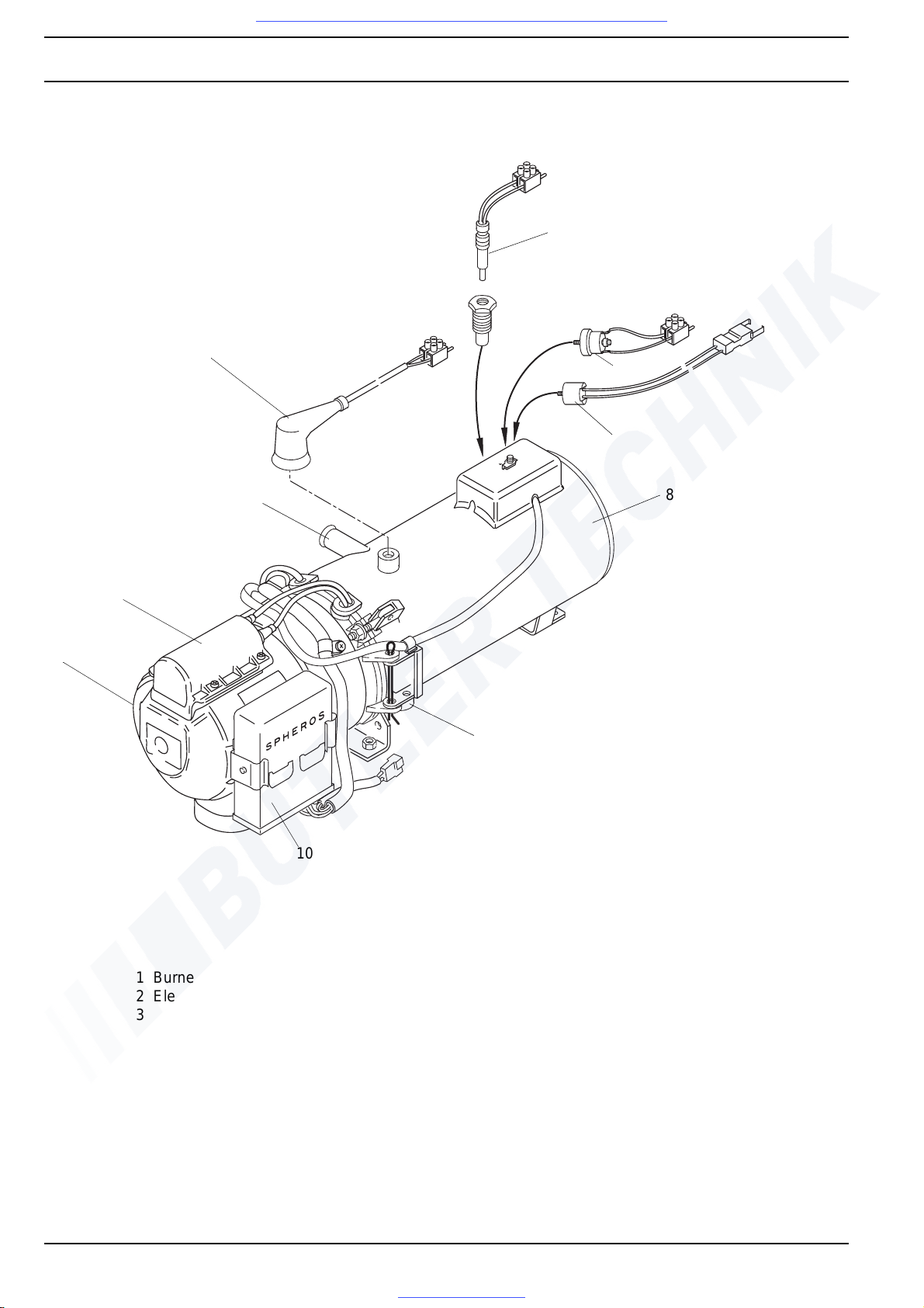
Heater DBW 160
1 Burner head
2 Electronic ignition unit
3 Coolant outlet
4 Control thermostat
5 Fusible link
6 Temperature limiter
7 Fan thermostat
8 Heat exchanger
9 Exhaust outlet
10 Control unit
8
7
6
4
3
2
1
9
10
5
Visit www.butlertechnik.com for more technical information and downloads.
www.butlertechnik.com
Page 13

DBW 160 / 230 (2020) / 300 / 350 2 General Description
203
Heater DBW 230, DBW 300 and DBW 350
1 Burner head
2 Electronic ignition unit
3 Coolant inlet
4 Fusible link *
5 Control thermostat *
6 Temperature limiter *
7 Coolant outlet
8 Heat exchanger
9 Fuel return
10 Fuel supply
11 Exhaust outlet
12 Control unit
* for components installed in applicable
heater variants
3
2
1
4
5
6
8
7
9
10
12
11
Visit www.butlertechnik.com for more technical information and downloads.
www.butlertechnik.com
Page 14

2 General Description DBW 160 / 230 (2020) / 300 / 350
204
2.1 Combustion air fan
The combustion air fan supplies the air required for combustion from the air intake into the combustion chamber.
Heaters are fitted with the following fan types:
DBW 160 – side-channel fan,
DBW 230 / 300 – radial fan,
DBW 350 – two-stage radial fan.
2.2 Motor
The motor drives the combustion air fan via a co up ling
and the fuel pump via a gearset.
2.3 Fuel pump
The fuel pump supplies fuel for combustion. It is driven by
the combustion air fan motor via a coupling. Inside the fuel
pump, the fuel is pressurised to approx. 10 bar (DBW 160
11.5 bar) and is vaporised by the high-pressure atomiser.
Fuel supply to the atomiser is controlled by a solenoid
valve.
DBW 160
DBW
230 / 300
DBW 350
DBW
300.62
DBW 160 /
230 / 300 /
350
Visit www.butlertechnik.com for more technical information and downloads.
www.butlertechnik.com
Page 15

DBW 160 / 230 (2020) / 300 / 350 2 General Description
205
2.3.1 Nozzle-block preheater
The nozzle-block preheater heats the fuel flowing to the
high-pressure nozzle.
Heaters without nozzle-block preheaters may show malfunctions at extremely low temperatures.
At temperatures < 0° C, the heating element in the nozzle
block is actuated via a thermostat.. Heating duration
depends on the heat reflected in the combustion chamber,
and the heater switches off when the thermostat reaches
a temperature of +8° C.
Heaters without nozzle-stock preheaters can be retrofitted.
For parts required please refer to parts list.
2.4 Heat exchanger
The heat exchanger transfers the heat generated by combustion into the cooling system.
DBW 160
Heating element
Nozzle block
Thermostat
DBW 230 /
300 / 350
Heating element
Nozzle block
Thermostat
DBW 160
to DBW
230(2020).32
to DBW
300.15
from DBW 230(2020).33
from DBW 300.15
from DBW 350.01
Visit www.butlertechnik.com for more technical information and downloads.
www.butlertechnik.com
Page 16

2 General Description DBW 160 / 230 (2020) / 300 / 350
206
2.5 Combustion chamber
The fuel/air mixture is distributed in the combustion
chamber where it is burned, thus heating the he at
exchanger.
2.6 Control unit
The control unit is the core control element ensurin g th e
system function and the monitoring of the combustion.
Control unit 1553
DBW 160
to
DBW 300.15
from
DBW 230(2020).33
DBW 300.16
DBW 300.62 without flame pipe
DBW 350.01
to
DBW 230(2020).32
Visit www.butlertechnik.com for more technical information and downloads.
www.butlertechnik.com
Page 17
DBW 160 / 230 (2020) / 300 / 350 2 General Description
207
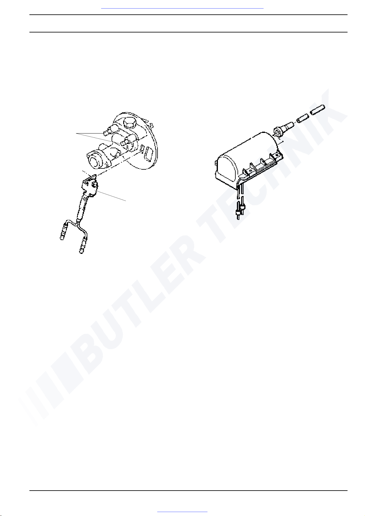
2.7 Flame sensor
The flame sensor monitors the flame during the entire
combustion process. The flame sensor acts as a photoelectric resistor detecting the absence of a flame or as a
photoelectric transistor detecting the presence of a flame
and responding to its luminous intensity.
Its signals are received and processed by the control unit.
Flame sensor for control unit 1553
2.8 Electronic ignition unit with ignition
electrodes
The electronic ignition unit creates the high voltage
required to ignite the fuel/air mixture. Ignition is then realised by high-voltage spark-over between the two ignition
electrodes.
Ignition
electrodes
Flame sensor
Visit www.butlertechnik.com for more technical information and downloads.
www.butlertechnik.com
Page 18
2 General Description DBW 160 / 230 (2020) / 300 / 350
208
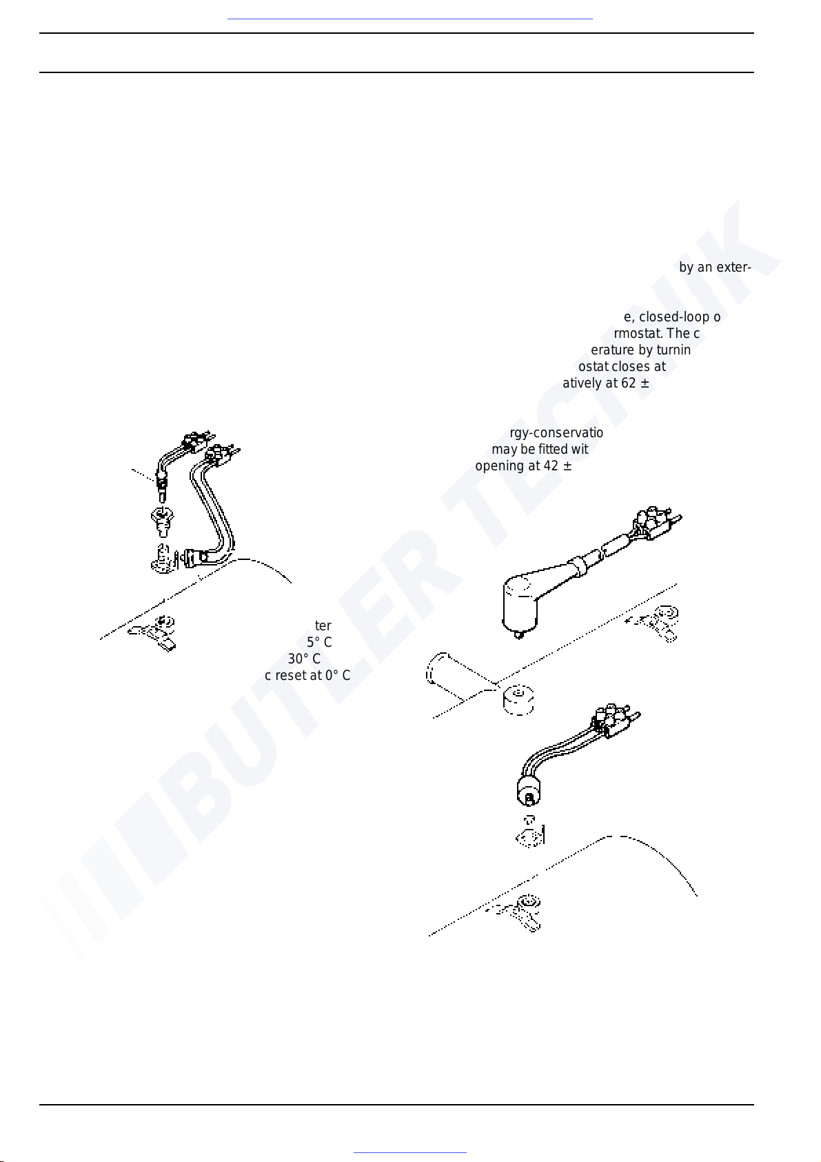
2.9 Temperature limiter / Thermal fuse
Temperature limiter
The temperature limiter (bi-metal) protects the heater
against excessive operating temperatures. The temperature limiter trips when a temperature of 107° C or 117° C
is exceeded, turning off the heater. The temperature
limiter is resetable or self-resetting.
Thermal fuse
The thermal fuse protects the heater against excessive
operating temperatures. It comprises a fusible link that
trips at excessive temperatures, turning off the heater.
Heaters can be retrofitted with temperature limiters
replacing the thermal fuses.
2.10 Control thermostat
Control thermostat at heater
After reaching operating temperature, closed-loop operation is performed by the control thermostat. The coolant is
maintained at a constant temperature by turning the
heater on and off. The thermostat closes at 63 ± 5° C and
opens at 70 ± 3° C.
External control thermostat
Closed-loop operation can also be executed by an exter-
nal control thermostat.
After reaching operating temperature, closed-loop operation is performed by the control thermostat. The coolant is
maintained at a constant temperature by turning the
heater on and off. The thermostat closes at 71 ± 2° C and
opens at 78 ± 2° C; alternatively at 62 ± 2° C and
70 ± 2° C.
Heaters with energy-conservation function (temperature
conservation) may be fitted with a thermostat closing at 35
± 2° C and opening at 42 ± 2° C.
Thermal
fuse
Reset
button
Temperature limiter
opens at 107 ± 5° C
resetable at 30° C
automatic reset at 0° C
DBW 160
DBW 230 / 300 / 350
Control thermostat at heater
Visit www.butlertechnik.com for more technical information and downloads.
www.butlertechnik.com
Page 19
DBW 160 / 230 (2020) / 300 / 350 2 General Description
209
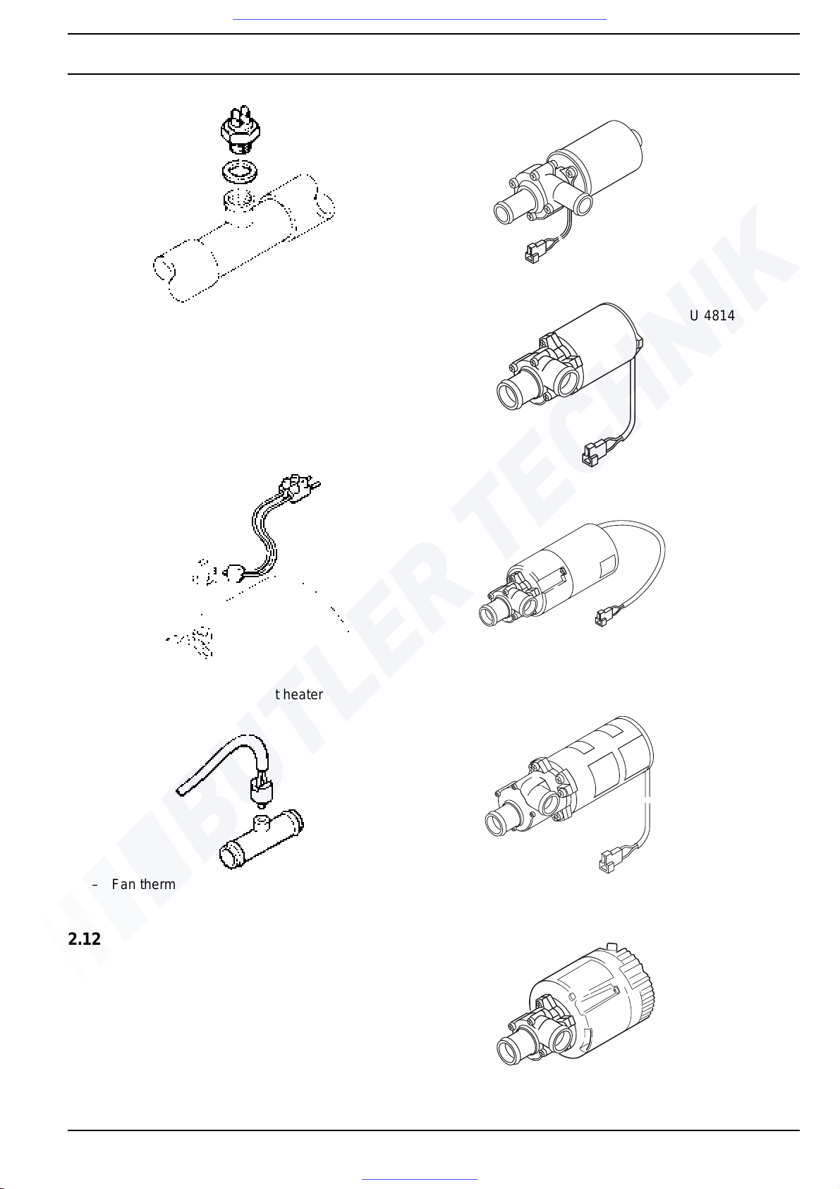
2.11 Fan thermostat
The fan thermostat turns the vehicle heater's fan on and
off at coolant temperatures between 30° C and 40° C. The
thermostat closes at 40 ± 3° C and opens at 30 ± 5° C.
Fan thermostat at heater
– Fan thermostat in coolant system
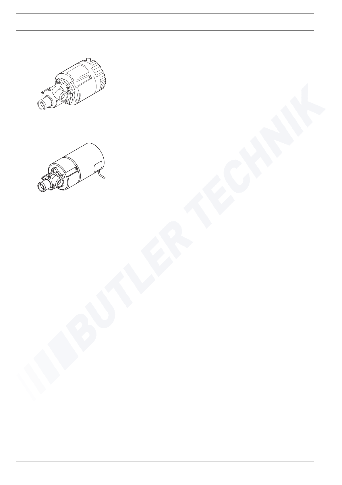
2.12 Circulation pump
The external circulation pump circulates the coolant in the
cooling system of the vehicle and in the heater. The pump
is activated by the control unit and runs througho ut the
entire operating period of the heater. Heaters are compatible with pumps of the type U 4810 (DBW 160 only),
U 4814, U 4851, U 4854, U 4855 or U 4856.
External control thermostat
U 4810
Recommended
for heater DBW
160
U 4814
Recommended
for heater DBW
230, 300 and
350
U 4851
Recommended
for heater DBW
230, 300 and 350
U 4854
Recommended
for heater DBW
230, 300 and
350
U 4855
(replaces
U 4851)
Recommended
for heater DBW
230, 300 and
350
Visit www.butlertechnik.com for more technical information and downloads.
www.butlertechnik.com
Page 20
2 General Description DBW 160 / 230 (2020) / 300 / 350
210
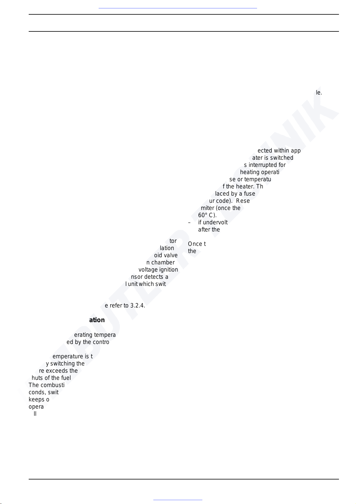
U 4856
(replaces
U 4852)
Recommended
for heater DBW
230, 300 and 350
U 4852
Recommended
for heater DBW
230, 300 and 350
Visit www.butlertechnik.com for more technical information and downloads.
www.butlertechnik.com
Page 21
DBW 160 / 230 (2020) / 300 / 350 3 Function Description
301
3 Function Description
3.1 General
The heaters are equipped with burners using high-pressure atomisers and run in intermittent operation. They are
thermostatically controlled (control unit 1553).
3.2 Operation
The heater is switched on and off at the
– switch (On/Off) or
– by the timer.
Its operating mode is shown by an operation indicator in-
tegrated in the timer or by a separate indicator light.
Heaters can be fitted with optional nozzle-block pre-
heaters and heater elements for operatio n at extremely
low temperatures.
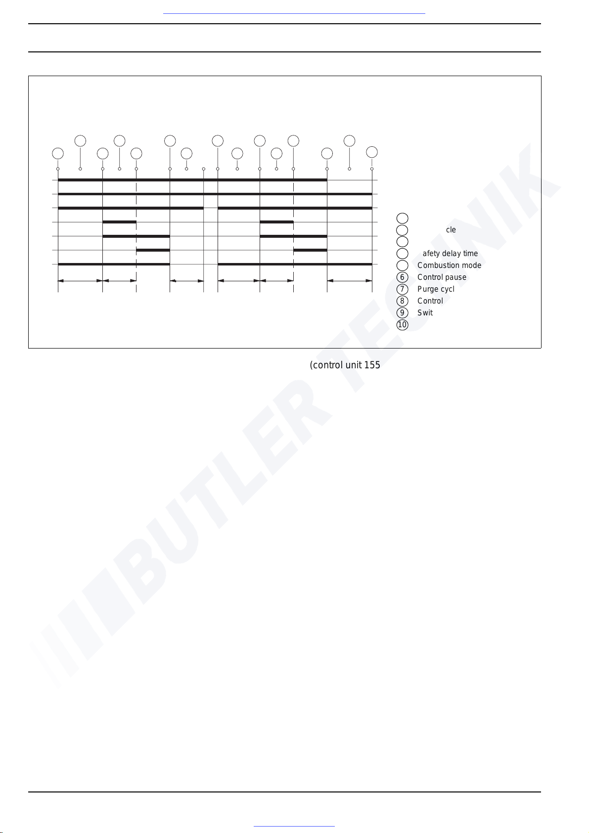
Operation (see Fig. 301)
3.2.1 Switch on
When the system is switched on, the operation indicator
lights up. Combustion air fan, fuel pump and circ ulation
pump start. After approx. 15 seconds, the solenoid valve
opens and fuel is injected into the combustion chamber
via the atomiser. At the same time, a high-voltage ignition
spark is generated. When the flame sensor detects a
flame, it outputs a signal to the control unit which switches
the electronic ignition unit off.
If no flame is detected, please refer to 3.2.4.
3.2.2 Heating operation
After reaching operating temperature, closed-loop operation is performed by the control thermostat.
Coolant temperature is then maintained at a constant
level by switching the heater on and off. When the temperature exceeds the upper switch point, the solenoid valve
shuts of the fuel supply, causing the flame to extinguish.
The combustion air fan then runs on for approx. 150 seconds, switching off automatically. The circulation pump
keeps on running during the burner's off-periods, and the
operation indicator remains on. When the temperature
falls below the lower switch point, the heater is restarted.
3.2.3 Switch off
When the heater is switched off, combustion is stopped.
The operation indicator is turned off, and the purge cycle
begins. Combustion air fan and circulation pump are
switched off after approx. 150 seconds.
The heater cannot be restarted during purge cycle.
3.2.4 Malfunction cut-out
Heaters with control unit 1553
A malfunction cut-out occurs
– if no combustion is detected within approx. 30
seconds after the heater is switched on,
– if the fuel supply is interrupted for more than 10
seconds during heating operation,
– if thermal fuse or temperature limiter detect over-
heating of the heater. The thermal fuse must always
be replaced by a fuse of the identical type (observe
colour code). Reset the button of the temperature
limiter (once the heater has cooled down to below
60° C).
– if undervoltage is detected approx. 10 – 25 seconds
after the temperature falls below the switch point.
Once the cause of the malfunction has been eliminated,
the heater can be unlocked by switching it off and back on.
Visit www.butlertechnik.com for more technical information and downloads.
www.butlertechnik.com
Page 22
3 Function Description DBW 160 / 230 (2020) / 300 / 350
302
Fig. 301 Function sequence (control unit 1553)
1
10
3
5
82 4 6
7
3
2 4
5 7
9
10-25 s 5-25 s
ca.150 s
10-25 s
5-25 s
ca.150 s
A
B
C
D
E
F
G
A Operation indicator
B Circulation pump
C Combustion air fan
D Electronic ignition unit
E Solenoid valve
F Flame sensor
G Control thermostat
1 Activation
2 Initial cycle
3 Start
4 Safety delay time
5 Combustion mode
6 Control pause starts
7 Purge cycle
8 Control pause ends
9 Switch-off
10 Heater stops
Visit www.butlertechnik.com for more technical information and downloads.
www.butlertechnik.com
Page 23
DBW 160 / 230 (2020) / 300 / 350 4 Technical Data
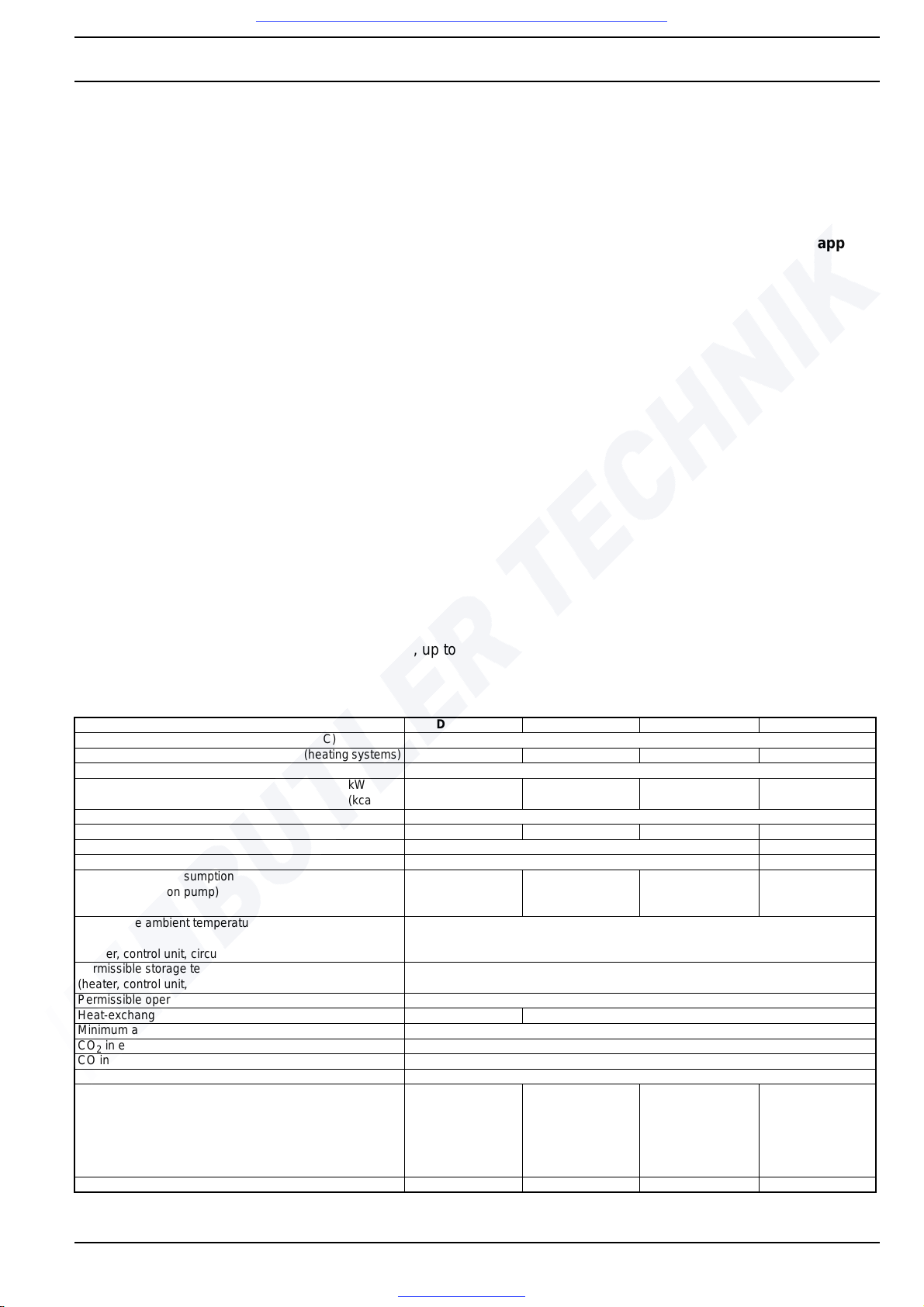
401
4 Technical data
Where no limit values are specified, technical data are understood to include standard tolerances for heaters of
±10% at an ambient temperature of +20° C and at nominal
voltage.
Electrical components
Control unit, motors for combustion air fan and circulation
pump, solenoid valve, electronic ignition unit, heating element, nozzle-block preheater and timer are designed for
24 volts. The components temperature limiter, flame
sensor, temperature sensor and switch are voltage-independent.
NOTE
Combinations of circulation pumps and heaters must be
selected in accordance with coolant flow resistance
Fuel
Only the type of fuel indicated on the heater's type label
may be used.
Commercially available diesel fuels in accordance with
DIN EN 590 (diesel fuel) may be used.
According to the diesel-fuel standard DIN EN 590, up to
5% of biodiesel additive is also permissible.
At temperatures below 0°C, a commercially available
winter diesel fuel should be used.
The use of flow improvers or additives is permissible.
Adverse effects are not known.
CAUTION:
For fuel taken from the vehicle tank, the vehicle manufacturer's specifications regarding additives apply.
Heater DBW 160 DBW 230 DBW 300 DBW 350
ECE approval number according to R10 (EMC) 025038
ECE approval number according to R122 (heating systems) 000204 000205 000206 000207
Build type High-pressure atomiser
Heat flow kW
(kcal/h)
16
(13 800)
23.3
(20 000)
30
(26 000)
35
(30 000)
Fuel Diesel fuel as per DIN 51601
Fuel consumption kg/h 1.9 2.5 3.3 3.7
Nominal voltage V – 12 or 24 24
Nominal-voltage range V – 10...14 / 21...28 21...28
Nominal power consumption
(without circulation pump)
W 100 (12V)
90 (24V)
110 (12V)
110 (24V)
100 (12V)
130 (24V)
.62: 100 (24V)
170 (24V)
Permissible ambient temperature during operation
(heater, control unit, circulation pump)
°C -40... + 60
Permissible storage temperature
(heater, control unit, circulation pump)
°C -40... + 85
Permissible operating pressure bar 0.4...2.0
Heat-exchanger filling capacity l 1.1 2.4
Minimum amount of coolant in circuit l 10.00 I
CO
2
in exhaust gas at nominal voltage Vol % 10.5 ± 0.5
CO in exhaust gas Vol % max. 0.2
Bacharach smoke number Vol % < 4.0
Heater dimensions (tolerance ± 3 mm) mm
mm
mm
length 584
width 205
height 228
length 681 to .32
length 680 to .50
width 230 to .32
width 240 to .50
height 279 to .32
height 269 to .50
length 681 to .15
length 680 to .30
width 230 to .15
width 240 to .30
height 279 to .15
height 269 to .30
length 725
width 240
height 279 to .10
height 269 from .11
Weight kg 14.5 24 from .33: 22 24 from .33: 22 23
Visit www.butlertechnik.com for more technical information and downloads.
www.butlertechnik.com
Page 24
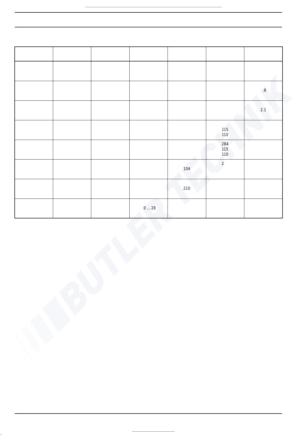
4 Technical Data DBW 160 / 230 (2020) / 300 / 350
402
Circulationpump type
Volume flow Nominal voltage
Operating
voltage range
Nominal power
consumption
Dimensions Weight
l/h V – V – W
length
width
height
kg
U 4810
1600 (at approx.
0.15 bar)
12 or 24 10 …14 / 20 …28 25
173
94
77
0.8
U 4814
5000 (at approx.
0.2 bar)
12 or 24 10 …14 / 20 …28 104
228
100
105
2.1
U 4851
6000 (at approx.
0.4 bar)
24 20 …28 209
279
115
110
2.7
U 4852
6000 (at approx.
0.4 bar)
24 20 …28 209
284
115
110
2.95
U 4854
5200 (at approx.
0.15 bar)
24 20 …28 104
221
100
105
2.1
U 4855
6000 (at approx.
0.4 bar)
24 20 …28 210
225
110
115
2.4
U 4856
6000 (at approx.
0.4 bar)
24 20 …28 210
229
110
115
2.5
Visit www.butlertechnik.com for more technical information and downloads.
www.butlertechnik.com
Page 25
DBW 160 / 230 (2020) / 300 / 350 5 Troubleshooting
501
5 Troubleshooting
5.1 General
CAUTION
The analysis and resolution of faults requires intimate
knowledge of the design and function of the heater's components and may be performed by qualified personnel
only.
When in doubt about the functional relationships, please
refer to sections 2 and 3.
CAUTION
Fault identification is usually limited to the identification of
defective components.
The following fault causes have not been considered a nd
should always be checked to eliminate these faults as
causes for malfunctions:
Corrosion on connector
Loose contact at connector
Crimping faults at connector
Corrosion at wiring and fuses
Corrosion at battery poles
A function check in the vehicle must be performed each
time a fault has been resolved.
5.2 General fault symptoms
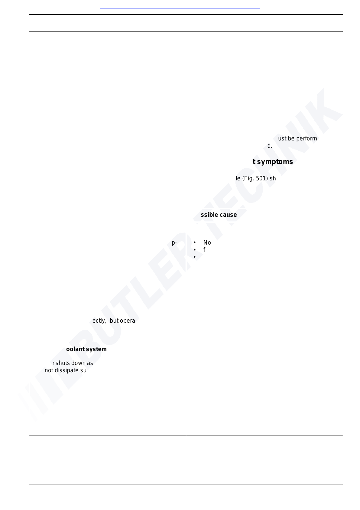
The following table (Fig. 501) shows general fault symptoms.
Fig. 501 General fault symptoms (page 1 of 2)
Fault symptom Possible cause
Faults in the electric system
Activation light does not light up, heater does not op-
erate.
• No voltage supply,
• fuses,
• Supply line to contacts of
connector A of control unit.
Fuse F2 blows. Short-circuit in circulation pump or
heater supply line.
Fuse F3 blows. Short-circuit in supply line to heater/motor/
nozzle-block preheater (if installed)
Heater functions correctly, but operation indicator
does not light up.
Operation indicator is defective or wiring
to operation indicator is interrupted or short-circuited.
Faults in coolant system
Heater shuts down as the connected heat exchangers
do not dissipate sufficient heat.
Flow rate insufficient because of
• air or gas in heater, heat
exchangers or system sections.
• Valves (flow controllers): restricted flow,
soiled, closed.
• System contamination, e.g. filter or tight spots.
• Insufficient feed from circulation pump (air or gas
in pump housing), reversed sense of rotation
– check wiring colours (black + / brown –)
• Insufficient anti-freeze protection,
Visit www.butlertechnik.com for more technical information and downloads.
www.butlertechnik.com
Page 26
5 Troubleshooting DBW 160 / 230 (2020) / 300 / 350
502
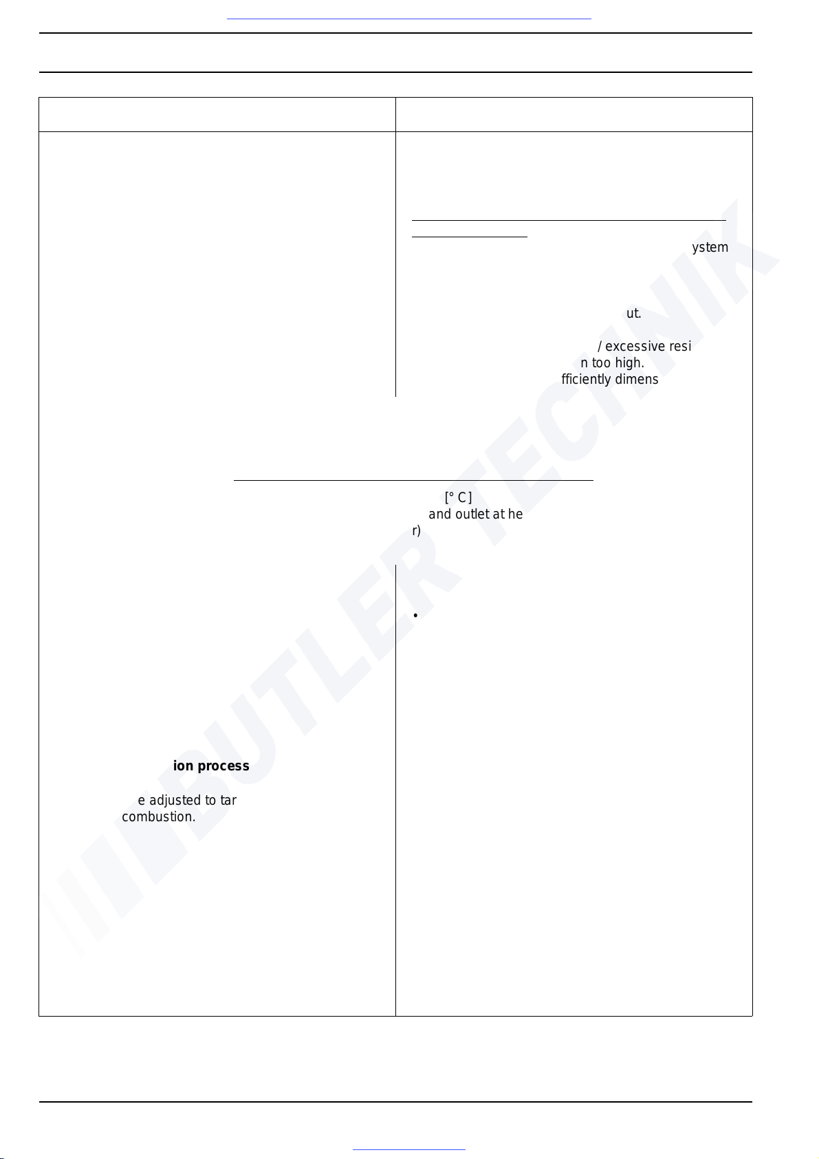
Fig. 501 General fault symptoms (page 2 of 2)
Fault symptom Possible cause
• Excessive system resistance (especially when
cold).
• Circulation pump defective
Heat exchangers (coolant/air) do not dissipate sufficient heat because
• of air or gas in the heat exchangers or in system
sections.
• Soiled thermal transfer surfaces
(inside/outside).
• Insufficient air intake or air output.
• Fan: insufficient flow /
reversed sense of rotation / excessive resistance.
• Anti-freeze concentration too high.
• Heat exchanger insufficiently dimensioned.
Estimation of flow rate
Heat flow [kW] acc. to type plate
Flow rate in [l/h] = x 860
Temperature difference Δt in [K] or [° C]
measured between coolant inlet and outlet at heater
(e.g. with contact thermometer)
Fault in fuel supply
No fuel supply to heater. • Fuel tank empty.
• Kinked, blocked, clogged or leaking lines.
• Paraffin wax separation or frozen water in fuel
filter or lines.
• Tank vent plugged.
• Fuel lines reversed.
• Fuel filter soiled.
Faults in combustion process
CO
2
cannot be adjusted to target value.
Unsmooth combustion.
• Air bubbles in suction line
(leak in suction line).
• Fuel filter soiled or leaking.
• Fuel supply system leaks
(suction height, vacuum in tank);
observe installation instructions.
• Fuel pump defective (pump pressure).
• Return line flow restricted.
• Pump strainer soiled.
• Atomiser defective.
• Combustion air and exhaust line flow restricted,
lines clogged.
• Burner motor speed too slow.
Visit www.butlertechnik.com for more technical information and downloads.
www.butlertechnik.com
Page 27
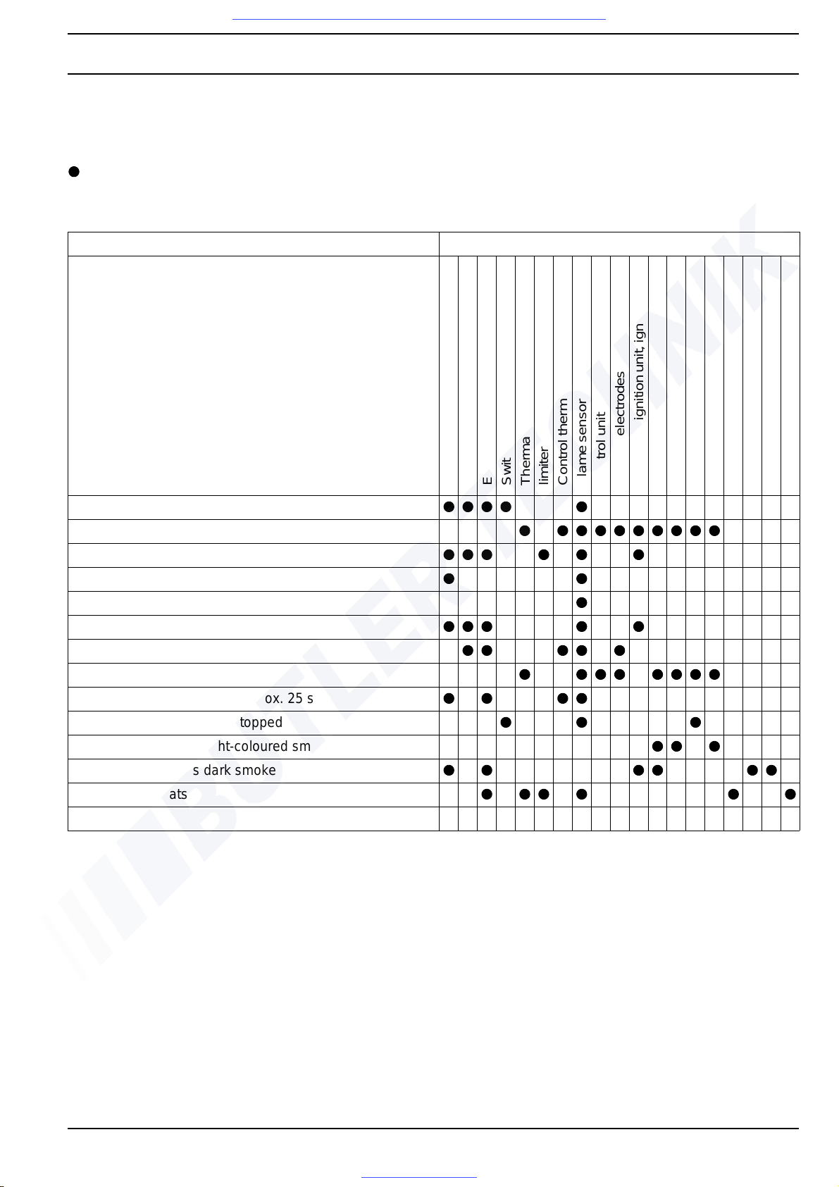
DBW 160 / 230 (2020) / 300 / 350 5 Troubleshooting
503
5.3 Troubleshooting – Quick diagnostic
Heater types:
all heaters
Fault symptom Check, repair, if required, replace
After activation – no function
Function indicator – extinguishes after approx. 25 s
Combustion air fan – does not run
Combustion air fan – no run-up
Combustion air fan – no run-down
Circulation pump – does not run
Ignition spark – not present
Combustion – does not start
Combustion – stops after approx. 25 s
Combustion – cannot be stopped
Combustion causes light-coloured smoke
Combustion causes dark smoke
Heater overheats
Power supply
Fuses
Electr. lines and connections
Switches
Thermal fuse and/or temperature
limiter
Control thermost.
Flame sensor
Control unit
Ignition electrodes
Electronic ignition unit, ignition cable
Drive (motor)
Fuel supply
Fuel pump
Fuel solenoid valve
Atomiser nozzle
Circulation pump
Combustion air duct
Exhaust duct
Visit www.butlertechnik.com for more technical information and downloads.
www.butlertechnik.com
Page 28
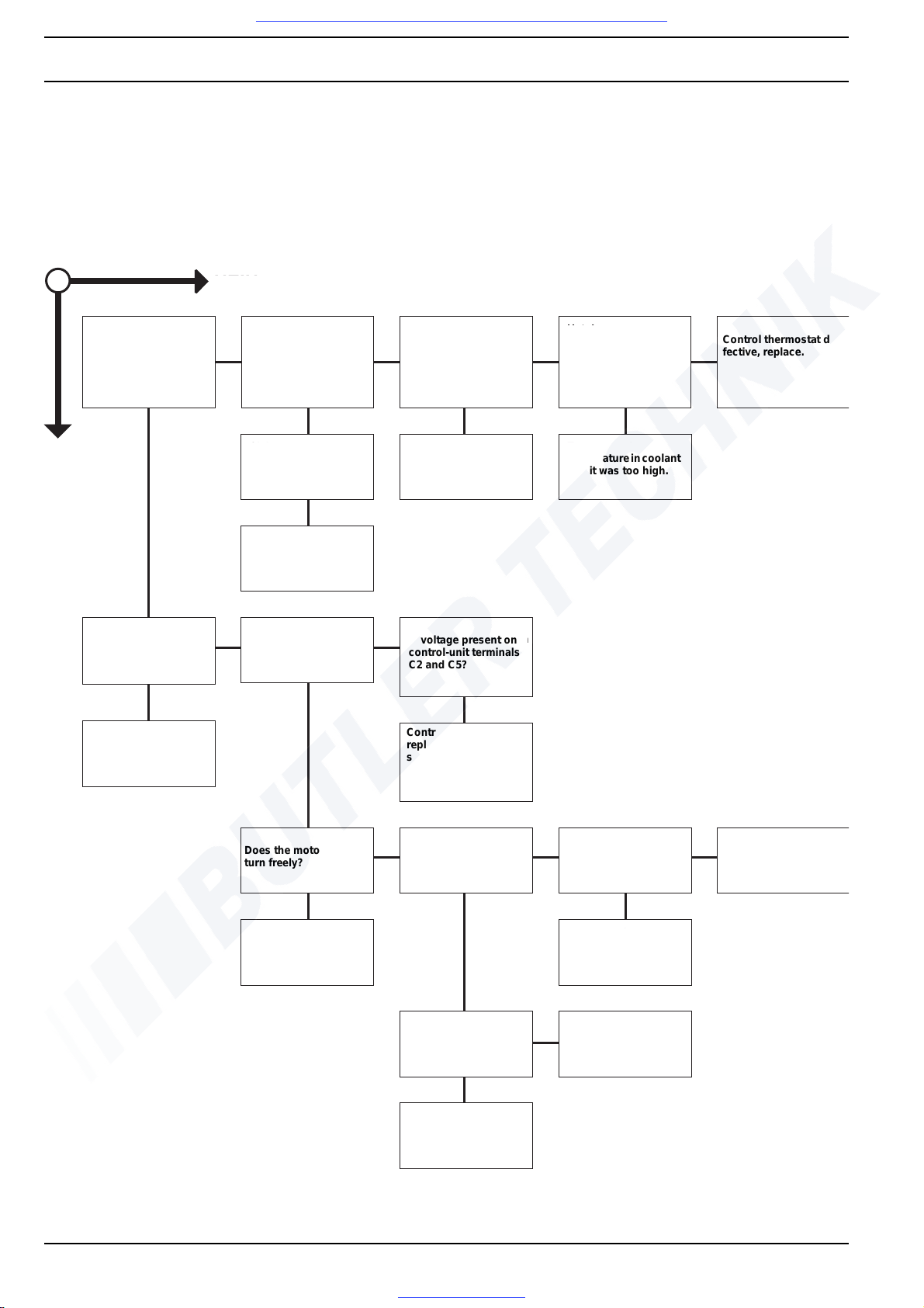
5 Troubleshooting DBW 160 / 230 (2020) / 300 / 350
504
5.4 Fault symptoms
5.4.1 Heater does not start when being
switched on
Liegt Spannung
an Klemmen B1, B2
und B4?
Hat der
Regelthermostat
Durchgang?
Hat der
Regelthermostat
nach Abkühlung des
Wasserkreislaufs
Durchgang?
Regelthermostat
defekt,
auswechseln.
JA
NEIN
Sind die beiden
Sicherungen F2/F3
defekt?
Zuleitung defekt
Temperatur im
Wasserkreislauf
war zu hoch.
Sicherungen aus-
wechseln und Heiz-
gerät einschalten. Löst
Sicherung wieder aus?
Kurzschluss suchen
und beseitigen.
Liegt Spannung
am Motor
(Brennluftgebläse)
an?
Spannung zu gering?
<18±1,0Vbzw.
< 9 ± 0,5 V
Unterspannung
schutz im Steuergerät
hat angesprochen;
Batterie laden.
Liegt Spannung an den
Klemmen C2 und C5
des Steuergerätes?
Steuergerät defekt,
auswechseln.
Zuleitungen zum Motor
(Brennluftgebläse) auf
Unterbrechung prüfen.
Lässt sich die
Motorwelle leicht
durchdrehen?
Lässt sich die Motor-
welle bei demontierter
Düsenstockplatte
leicht durchdrehen?
Lässt sich die
Motorwelle bei
demontiertem Motor
leicht durchdrehen?
Motor
(Brennluftgebläse)
defekt,
auswechseln.
Motor
(Brennluftgebläse)
defekt, auswechseln.
Lagerung des
Gebläserades defekt.
Lässt sich das
große Stirnrad
leicht durchdrehen?
Brennstoffpumpe
defekt,
auswechseln.
Motor
(Brennluftgebläse)
defekt, auswechseln.
NO
Y
ES
Is voltage present on
terminals B1, B2 and
B4?
Are the two F2/F3
fuses defective?
Does the control thermostat have continuity?
Does the control thermostat have continuity
after the coolant circuit
has cooled down?
Control thermostat defective, replace.
Replace fuses and
switch heater on. Does
the fuse trip again?
Supply line defective
Temperature in coolant
circuit was too high.
Find short circuit and
eliminate it.
Voltage too low? < 18 ±
1.0 V or < 9 ± 0.5 V
Is voltage present at
the motor of the combustion air fan?
Is voltage present on
control-unit terminals
C2 and C5?
Voltage too low?
<18 ± 1.0 V or < 9 ± 0.5 V
Undervoltage protection in control unit was
triggered; charge battery.
Control unit defective,
replace. Check motor
supply lines (combustion air fan) for interruption.
Does the motor shaft
turn freely?
Does the motor shaft
turn freely with the
nozzle-block plate removed?
Does the motor shaft
turn freely with the
motor removed?
Motor (combustion air
fan) defective, replace.
Motor (combustion air
fan) defective, replace.
Fan-wheel bearing
defective.
Does the large spur
gear turn freely?
Fuel pump defective,
replace.
Motor (combustion air
fan) defective, replace.
Visit www.butlertechnik.com for more technical information and downloads.
www.butlertechnik.com
Page 29
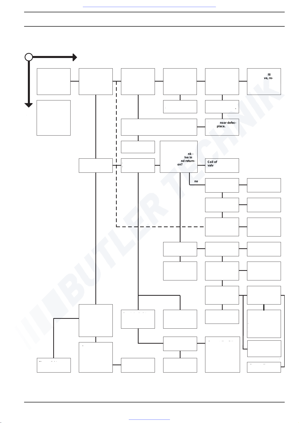
DBW 160 / 230 (2020) / 300 / 350 5 Troubleshooting
505
5.4.2 Heater repeatedly switches into malfunction mode approx. 30 s after being switched on
Has thermal fuse F1
tripped? Was the temperature limiter triggered?
NO
Y
ES
Is the buzzing of the
(mechanical) electronic ignition unit
audible after approx.
20 s to 12 s?
Is voltage present on
terminals C8 and C5?
Check supply lines
from control unit. Interruption?
Does symptom still
occur with a new electronic ignition unit?
Electronic ignition
unit defective, re-
place.
Eliminate cause for
tripping, e.g. lack of
coolant. Renew
thermal fuse or reset
temperature limiter.
Eliminate
interruption.
Ignition-electrode
insulation defective.
Is the resistance / voltage of the flame sensor
> 100 kOhm without exposure to light?
Flame sensor defec-
tive, replace.
Control unit defective, replace.
Is combustion noise
audible?
Does fuel spray from
the atomiser nozzle?
Does the solenoid
valve in the heater
open and - if present
due to elevated tank -
the solenoid valve in
the suction and return-
flow position?
no
yes
Do the solenoid
valves have continuity?
Solenoid valve defective, replace.
Is voltage present at
the solenoid valve?
Check supply lines.
Is the position of the
ignition electrodes
correct when
checked with gauge?
Align ignition electrodes using gauge.
Does the pump
supply fuel?
Is there fuel in the
tank?
Refill
Atomiser nozzle
clogged, replace.
Are all fuel lines
tightly connected?
Retighten, replace
seals.
Is the sealing surface
of the control plunger
or the vent soiled?
Remove fuel pump, is
the drive lug at the
shaft ok?
Is the resistance /
voltage of the flame
sensor < 1.56 kOhm
if exposed to a light
intensity of 50 Lux?
Does the nozzle
create a defined spray
cone?
Check intake and
exhaust port for free
flow, clean if required.
Clean or replace.
Suction line clogged.
Paraffin wax separation or frozen water
inclusions. Or: tank
vent plugged.
Is the viscosity
below 20 cSt.?
Fuel quality does not
correspond to the
mixture specified in
the operating
manual for low temperatures.
Screen in the suction
connection for fuel
pump soiled, clean.
no
no
yes
yes
Flame sensor defective, replace.
Voltage at heater is
in limit range of
control unit's undervoltage protection.
Charge battery.
Atomiser nozzle
clogged, replace.
Replace fuel pump.
Coil of solenoidvalve head defective.
Visit www.butlertechnik.com for more technical information and downloads.
www.butlertechnik.com
Page 30
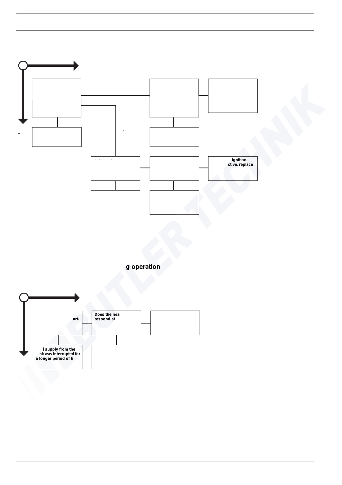
5 Troubleshooting DBW 160 / 230 (2020) / 300 / 350
506
5.4.3 Heater requires several attempts to start
5.4.4 Heater turns off by itself during operation
Tritt bei den
vergeblichen
Startversuchen
Qualm aus dem
Abgasrohr?
Brennstoffspiegel ist
beim Stillstand des
Heizgerätes abgefallen:
Saug- und Rücklauf-
leitung abdrücken.
Sind Undichtigkeiten
feststellbar?
Brennstoffpumpe
defekt, auswechseln.
Druckregelventil
verstopft.
JA
NEIN
Abdichten.
Schlägt der
Zündfunke an den
Hochspannungs-
leitungen über?
Zündfunkengeber
defekt, auswechseln.
Hochspannungsleitung
defekt
Siehe 5.4.7
Schlägt der
Zündfunke an der
Isolierung der
Zündelektroden über?
Zündelektrode
defekt, auswechseln.
nein
nein
NO
YES
Is smoke emitted
from the exhaust pipe
during the vain startup attempts?
Fuel level has sunk
during heater standstill:
pressure-check suction
and return line. Are
leaks present?
Fuel pump defective,
replace it.
Pressure control valve
blocked.
See 5.4.7
Seal
Is there spark-over
between the highvoltage lines?
Is there spark-over at
the insulation of the ignition electrodes?
Electronic ignition
unit defective, replace
it.
High-voltage line defective
Ignition electrode defective, replace.
no
no
NO
YES
Does the heater function after another start-
up attempt?
Does the heater
respond at all?
See 5.4.1
Fuel supply from the
tank was interrupted for
a longer period of time.
Heater switches into
malfunction mode after
approx. 30 s, see 5.4.2
Visit www.butlertechnik.com for more technical information and downloads.
www.butlertechnik.com
Page 31
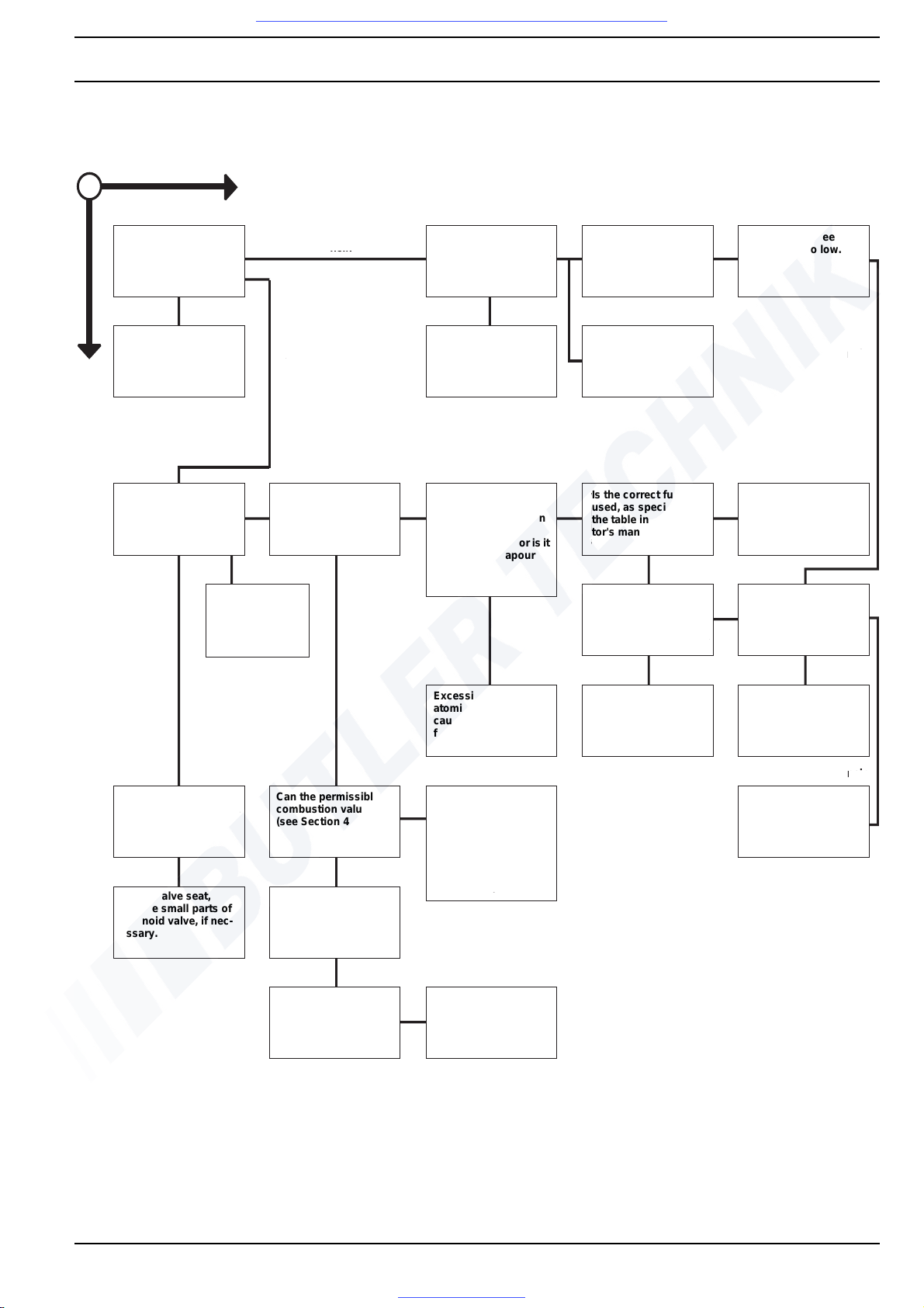
DBW 160 / 230 (2020) / 300 / 350 5 Troubleshooting
507
5.4.5 Heater creates black smoke
NO
Y
ES
Are combustion air
intake pipe or exhaustgas outlet soiled?
Are the gas ducts of
the heat exchanger
heavily soiled?
Is there vacuum or
overpressure at the
combustion air inlet,
possibly also while
driving?
Clean, adjust installation, if necessary (see
Section 8).
Clean according to instructions.
Swirler (in DBW 160)
defective? Protective
cap of burner/ grommets untight?
Does the heater
produce black smoke
during start-up only?
Has the fuel/air ratio
changed?
Are there tight spots or
spots with restricted
flow in the fuel-retu r n
line or does the
suction line leak or is it
overheated (vapour
bubbles)?
Is the correct fuel
used, as specified in
the table in the operator's manual?
Observe notes in the
operator's manual.
Let heater burn
off deposits.
Check fuel-pump pressure (see Section 6). Is
the pump-pressure too
high?
Is voltage present at
the motor under load
below 10 V or 20 V?
Excessive flow rate at
atomiser nozzle
caused by increased
fuel pressure.
Adjust (see Section 6).
Charge battery; electrical lines corroded or
cross-section insufficient; motor defective.
no
no
no
no
Solenoid valve seat
leaks? (valve seat
damaged, armature
stuck)
Can the permissible
combustion values
(see Section 4) be set?
Clearance between fan
wheel and housing too
large (for DBW 160) or
motor speed too low
(see Section 6).
Check valve seat,
replace small parts of
solenoid valve, if nec-
essary.
Replace atomiser
nozzle.
Does the heater continue to produce black
smoke after the settings have been
changed?
Does the atomiser
nozzle spray evenly?
Clean or replace atomiser nozzle.
Motor speed (see
Section 6) too low.
Visit www.butlertechnik.com for more technical information and downloads.
www.butlertechnik.com
Page 32
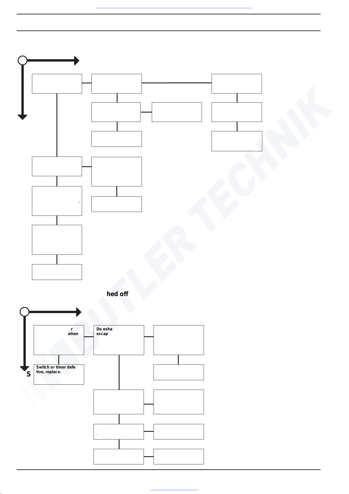
5 Troubleshooting DBW 160 / 230 (2020) / 300 / 350
508
5.4.6 Heater creates white smoke
5.4.7 Heater cannot be switched off
NO
ES
Does the heater
produce smoke for
more than 20 s?
Does the heater produce
smoke during operation
(also erratically)?
Does the heater
produce smoke after it
has been shut off?
Is the electrode position
correct when checked
with a gauge (see
Section 6)?
Align ignition electrodes using gauge
(see Section 6).
Does the solenoidvalve seat not close
properly?
Replace atomiser
nozzle.
Check solenoid-valve
seat, replace small
parts, if necessary.
Have several unsuccessful start-up attempts been made?
Is the flow rate of the
atomiser nozzle too
low? -Replace. Does
the heater still produce
smoke?
Oil accumulated in the
combustion chamber
must first evaporate.
Does the heater continue to produce smoke?
Replace atomiser
nozzle.
Open burner and pull
out combustion chamber. Is a carbon
deposit visible in the
combustion chamber?
Clean combustion
chamber.
NO
YES
Do switch or timer
have continuity when
switched off?
Do exhaust gases still
escape after shut-off?
Does the heater run on
for more than 180 s
after it has been shut
off?
Switch or timer defective, replace.
Control unit defective,
replace.
Does the control thermostat open when the
switching point is
reached?
Control thermostat defective, replace.
Is there voltage loss at
the solenoid valve?
Control unit defective,
replace.
Does the solenoid
valve close?
Solenoid valve defective, replace.
Visit www.butlertechnik.com for more technical information and downloads.
www.butlertechnik.com
Page 33
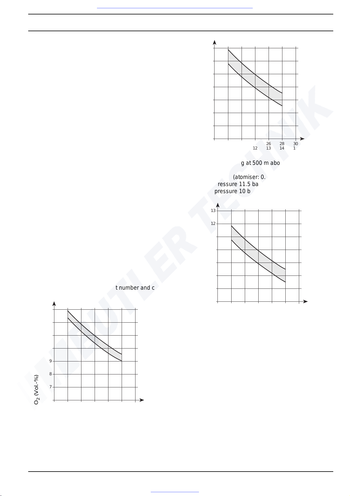
DBW 160 / 230 (2020) / 300 / 350 6 Function Checks
601
6 Function Checks
6.1 General
This section describes the checks and settings to be performed on the installed and removed heater to verify its
fitness for operation.
WARNING
The heater must never be operated in enclosed rooms
such as garages or workshops without exhaust-gas extraction systems.
Risk of fire! Do not switch on the heater with the burner
swung away from its operating position.
6.2 Settings
6.2.1 Adjusting CO2 contents
The combustion air quantity set at the factory may be
changed by turning the adjustment ring.
The CO
2
content of the exhaust must be measured and
the combustion air quantity must be adjusted, if required:
– after repair of the burner
– in case of irregular combustion
– during function checks
– after atomiser replacement
Adjustment procedure
– Measure input voltage at heater
– Run heater for approx. 5 min.
–Measure CO
2
and smoke spot number and compare
with applicable diagram.
DBW 160 (atomiser: 0.3 gph)
DBW 230(2020)(
>
=
.33)
DBW 300 / DBW 350
Fuel-pump pressure 10 bar
DBW 160 (atomiser: 0.4 gph)
Fuel-pump pressure 11.5 bar (0.4 gph)
Fuel-pump pressure 10 bar (0.3 gph)
DBW 230(2020)(
<
=
.32)
DBW 300 (
<
=
.15)
Fuel-pump pressure 10 bar
Voltage
CO
2
setting at 500 m above sea level
CO
2
(Vol.-%)
18 20 22 24 26 28 30
6
7
8
9
10
11
12
13
9101112131415
18 20 22 24 26 28 30
6
7
8
9
10
11
12
13
9101112131415
Voltage
CO
2
setting at 500 m above sea level
CO
2
(Vol.-%)
18 20 22 24 26 28 30
6
7
8
9
10
11
12
13
9101112131415
Voltage
CO
2
setting at 500 m above sea level
CO
2
(Vol.-%)
Visit www.butlertechnik.com for more technical information and downloads.
www.butlertechnik.com
Page 34
6 Function Checks DBW 160 / 230 (2020) / 300 / 350
602
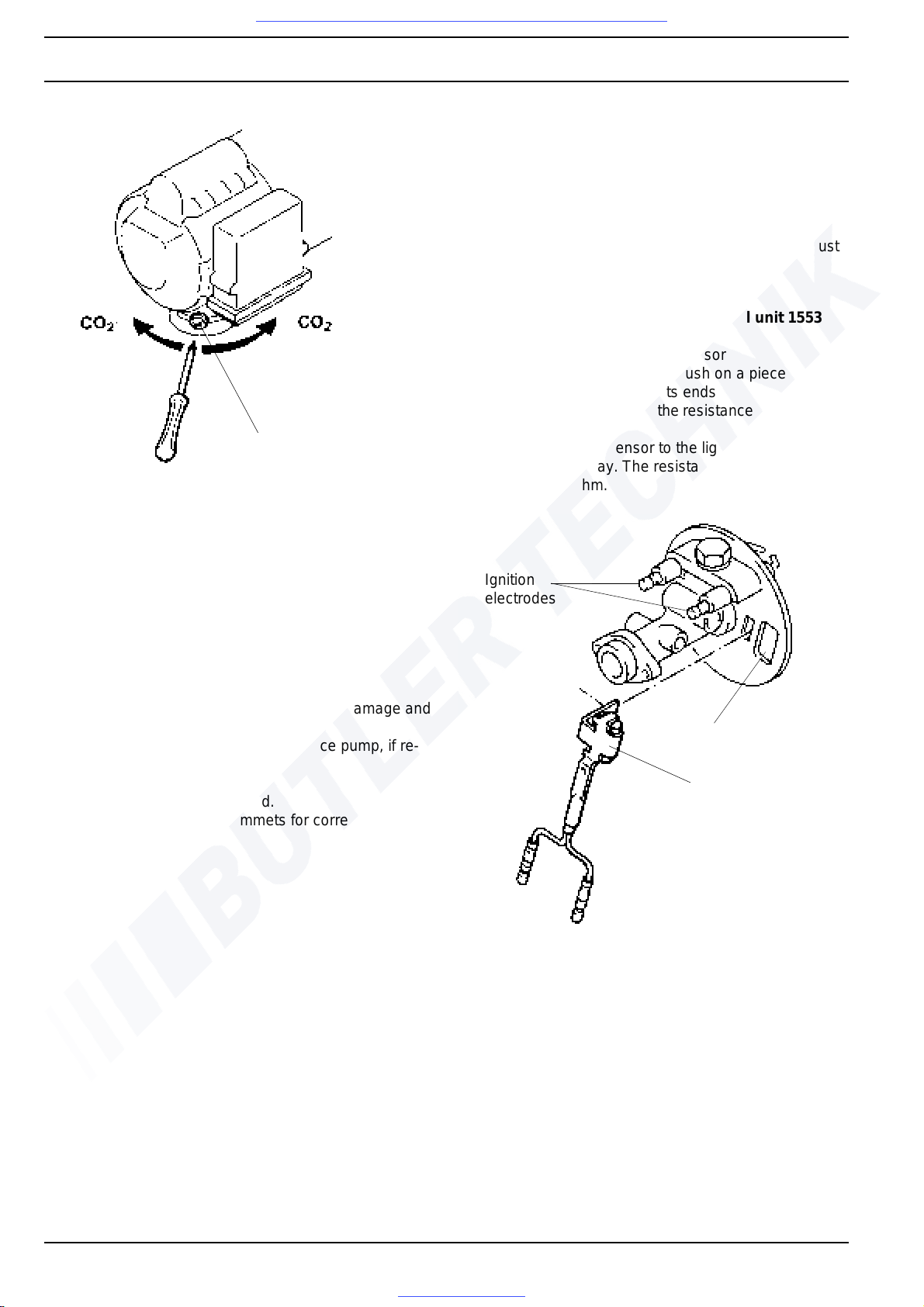
– Release locking bolt (see Fig.) and move the adjust-
ment ring with the locking bolt until the target value is
achieved.
– Torque locking bolt to 1.0 +0.5 Nm an d secure it with
locking compound.
NOTE
The CO
2
setting depends on the fuel (visco-sity) and the
height above sea level (0.1% per 100 m).
If the CO
2
value cannot be adjusted to target value
proceed as follows:
– Check air intake side of bur ne r h ead for d ama ge and
replace, if required
– Check fuel pump pressure and replace pump, if re-
quired
– Replace atomiser
– Measure burner motor speed.
– Check wiring conduit grommets for correct installa-
tion.
6.3 Checks of individual components
6.3.1 Check of flame sensor resistance
NOTE
The glass body of the flame sensor and the sight glass
(see Fig.) must be cleaned if soiled. In case of damage or
if the target value is not reached, the flame sensor must
be replaced.
6.3.1.1 Check of flame sensor at control unit 1553
– Connect ohmmeter to flame sensor
– Black out the flame sensor. Push on a piece of black
insulating hose and pinch its ends
– After approx. 20 seconds the resistance must inrease
to > 100 k-Ohm
– Expose the flame sensor to the light of a match lit
approx. 1 cm away. The resistance must drop to
approx. 300 Ohm.
Locking bolt
NOTE
The intake duct may be
rotated by 180°.
+
–
Sight glass
Ignition
electrodes
Flame sensor
Visit www.butlertechnik.com for more technical information and downloads.
www.butlertechnik.com
Page 35
DBW 160 / 230 (2020) / 300 / 350 6 Function Checks
603
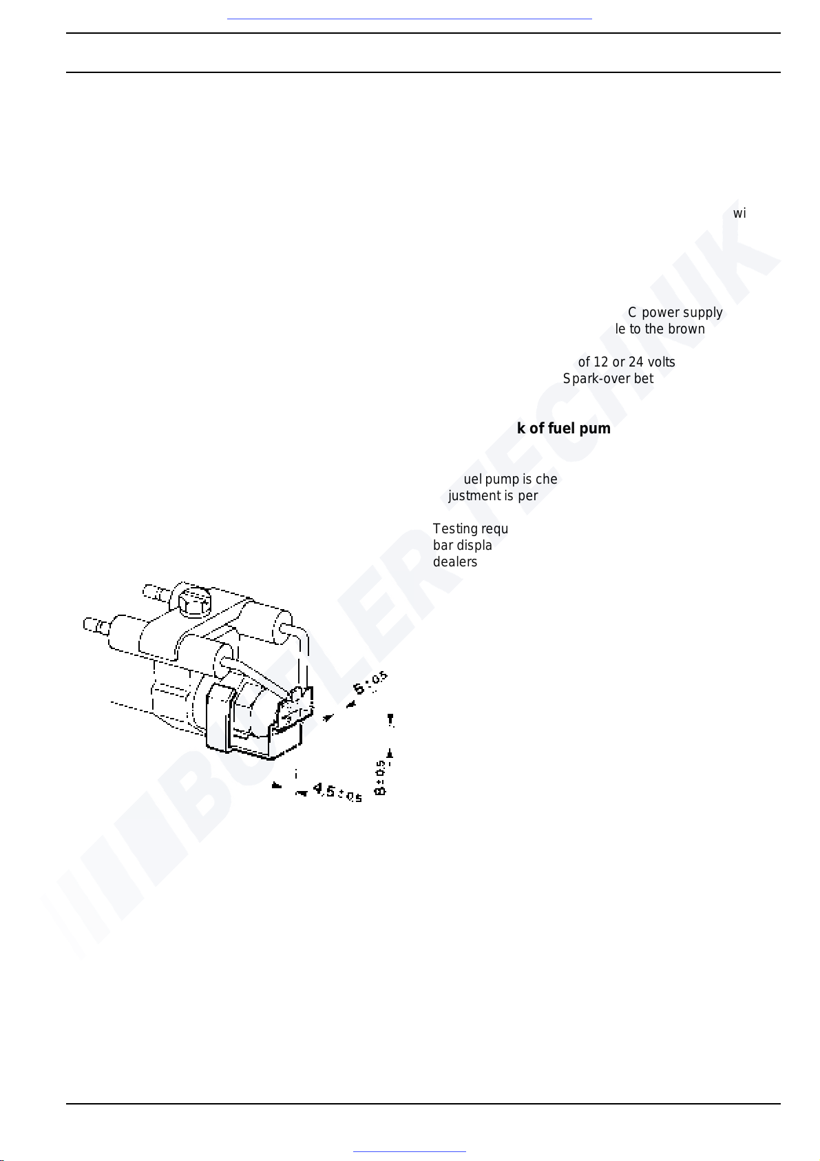
6.3.2 Check and adjustment of ignition
electrodes
NOTE
• The ignition electrodes' insulation bodies may not
show any signs of damage. Ignition electrodes with an
electrode gap outside the tolerance range or incorrectly functioning ignition electrodes must be adjusted
or replaced.
• Ignition electrode gaps can be adjusted using the
gauge. The gauge's front edge must contact the atomiser with the tips of the ignition electrodes resting in
the two notches.
Check
– Check the ignition electrodes' insulation bodies for
signs of damage.
CAUTION
In order not to disturb fuel a tomisation , the atomizer bore
must not be touched while measuring the electrode gap.
– Check electrode gap using the g auge as shown in the
fig. and check the condition of the electrodes.
Adjustment
– Adjust gap by bending electrodes and verify using the
gauge as shown.
6.3.3 Check of electronic ignition unit
WARNING
High voltage; the spark generated at the ignition electrodes has a voltage of approx. 8,000 volts.
CAUTION
Never apply voltage to the electronic ignition unit without
the ignition electrodes being installed.
Check
NOTE
Connect the positive pole of a DC power supply to the
black line and the negative pole to the brown line.
– Apply a DC voltage of 12 or 24 volts.
– Target condition: Spark-over between ignition elec-
trodes.
6.3.4 Check of fuel pump
NOTE
The fuel pump is checked when installed. Pump-pressur e
adjustment is permissible.
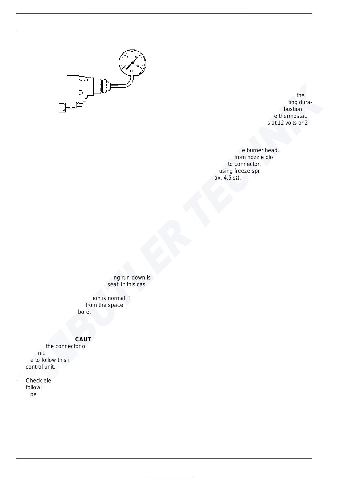
Testing requires a testing device. Testing devices (0 to 15
bar display range) are available from Spheros main
dealers.
CAUTION
The electronic ignition unit must be removed.
Check
– Remove electronic ignition unit (see 9.2.7.1).
– Remove atomiser.
– Install testing device.
– Cover flame sensor.
– Turn on heater.
– Pump pressure is indicated after ap prox. 15 secon ds
(see diagram).
– Turn off heater.
– Remove testing device.
CAUTION
Do not damage atomiser bore.
– Screw in atomiser nozzle and tighten to 20 Nm.
Visit www.butlertechnik.com for more technical information and downloads.
www.butlertechnik.com
Page 36
6 Function Checks DBW 160 / 230 (2020) / 300 / 350
604
– Install electronic ignition unit (see 9.2.7.2).
6.3.5 Check of burner motor
NOTE
The combustion air fan is checked when installed. T he fan
motor must be replaced if the target conditions are not
achieved.
Check
– Check bearings of burner motor (mu st be freely run-
ning).
– Measure input voltage at heater
– Turn on heater.
– Measure speed (at nominal voltage, the spe eds must
be within the specified ranges).
DBW 160 .......4050 – 4950
DBW 230 .......5220 – 6380
DBW 300 .......5220 – 6380
DBW 350 .......5040 – 6160
6.3.6 Check of solenoid valve
NOTE
Longer periods of smoke emission during run-down is an
indication of a leaking solenoid valve seat. In this case fuel
trickles from the atomiser.
A short period of smoke emission is normal. This is
caused by the fuel draining from the space between solenoid valve and atomiser bore.
Check
CAUTION
Disconnect the connector of the solenoid valve at the
control unit.
Failure to follow this instruction may result in damage of
the control unit.
– Check electric function of 12-volt devices using the
following data:
• Opening voltage 8.5 volts
• Operating voltage 9.6 ... 14.4 volts
• Power consumption at
• nominal voltage and 20° C 10 watts
• nominal current 0.83 ampere
– Check electric function of 24-volt devices using the
following data:
• Opening voltage 17.0 volts
• Operating voltage 19.2 ... 28.8 volts
• Power consumption at
• nominal voltage and 20° C 10 watts
• nominal current 0.42 ampere
6.3.7 Check of nozzle-block preheater
NOTE
At temperatures of < 0° C the thermostat activates the
heater element inside the nozzle block. The heating dura-
tion depends on the reflection heat in the combustion
chamber and is switched off at +8° C at the thermostat.
The power consumption is 130 ±13 watts at 12 volts or 24
volts.
Check
– Swing away or remove the burner head.
– Disconnect connector from nozzle block.
– Connect ohmmeter to connector.
– Chill thermostat using freeze spray or bridge it.
– Resistance (max. 4.5 Ω).
Visit www.butlertechnik.com for more technical information and downloads.
www.butlertechnik.com
Page 37
DBW 160 / 230 (2020) / 300 / 350 6 Function Checks
605
Notes
Visit www.butlertechnik.com for more technical information and downloads.
www.butlertechnik.com
Page 38
6 Function Checks DBW 160 / 230 (2020) / 300 / 350
606
Visit www.butlertechnik.com for more technical information and downloads.
www.butlertechnik.com
Page 39
DBW 160 / 230 (2020) / 300 / 350 7 Circuit diagrams
701
7Wiring diagrams
7.1 General information
The wiring diagrams and application examples
(Fig. 701 to 704) show possible circuits for the heaters
DBW 160, 230 (2020), 300 and 350.
Visit www.butlertechnik.com for more technical information and downloads.
www.butlertechnik.com
Page 40
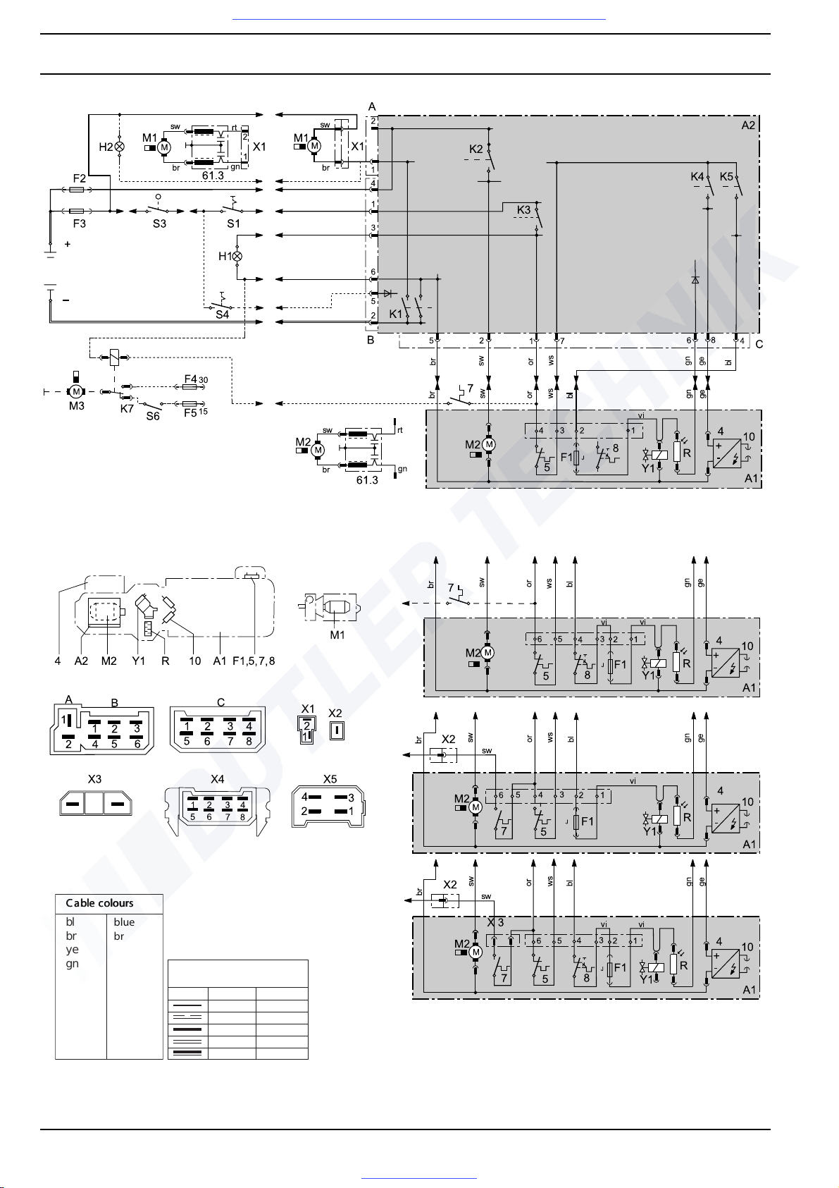
7 Circuit diagrams DBW 160 / 230 (2020) / 300 / 350
702
Fig. 701 (page 1 of 2) Automatic wiring diagram, DBW 160 with control unit 1553 and switch,
system variants and pin allocation
bl
br
ye
gn
gr
or
rd
bl
vi
wh
eeelllbbbaaaCCCsssrrruuuooollloooccc
blue
brown
yellow
green
grey
orange
red
black
violet
white
gggnnniiirrriiiWWWsssnnnoooiiitttccceeesss---ssssssooorrrccc
< 7.5 m 7.5 - 15 m
0.75 mm
2
1.0 mm
2
1.5 mm
2
2.5 mm
2
4.0 mm
2
1.5 mm
2
1.5 mm
2
2.5 mm
2
4.0 mm
2
6.0 mm
2
Visit www.butlertechnik.com for more technical information and downloads.
www.butlertechnik.com
Page 41
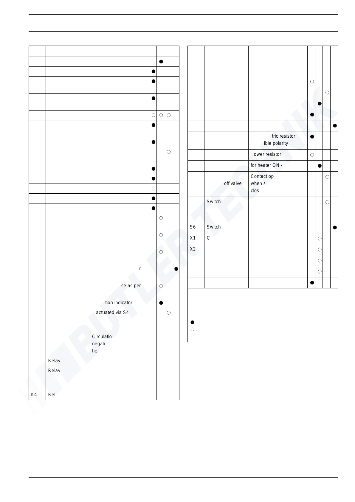
DBW 160 / 230 (2020) / 300 / 350 7 Circuit diagrams
703
Pos. Designation Comment A B C D
A1 Heater
A2 Control unit CU 1553
4 Electronic ignition
unit
5 Thermostat Control thermostat (inter-
nal)
7 Thermostat Fan thermostat
8 Thermostat Temperature-limiter ther-
mostat
10 Ignition electrodes
61.3 Interference-sup-
pression kit (2 x)
Interference suppression
A Connector Control unit, 2-pin
B Connector Control unit, 6-pin
B5 Thermostat Nozzle-block preheater
C Connector Control unit, 8-pin
F1 Thermal fuse reversible polarity
F2 8 A fuse Automotive fuse as per
DIN 72581
F3 8 A fuse Automotive fuse as per
DIN 72581
F4 Fuse Automotive fuse as per
DIN 72581
F5 Fuse Automotive fuse as per
DIN 72581
F6 Fuse Automotive fuse as per
DIN 72581
H1 Light, green Operation indicator
H2 Light,
for circulation
pump
If actuated via S4
K1 Relay Circulation pump;
negative terminal for
heater
K2 Relay Heater motor
K3 Relay Light;
control-thermostat opera-
tion
K4 Relay Electronic ignition unit
Pos. Designation Comment A B C D
K5 Relay Solenoid valve; flame
sensor
K6 Relay Nozzle-block preheater
K7 Relay Vehicle-heater fan
M1 Motor Circulation pump
M2 Motor Combustion air fan
M3 Motor Vehicle fan
R Flame sensor Photoelectric resistor,
reversible polarity
R1 Motor resistor Power resistor
S1 Switch for heater ON - OFF
S3 Switch
on shut-off valve
Contact open
when shut-off valve
closed
S4 Switch for ON - OFF,
with separate connection
of circulation pump
S6 Switch Vehicle fan
X1 Connector 2-pin
X2 Connector 1-pin
X3 Connector 2-pin
X5 Connector 4-pin
Y1 Solenoid valve reversible polarity
A
B
C
D
installed in heater
unmounted supply parts
only if required
included in vehicle equipment
fixed allocation
possible depending on the scope of delivery or design type
Fig. 701 (page 2 of 2) Automatic wiring diagram, DBW 160 with control unit 1553 and switch,
system variants and pin allocation
Visit www.butlertechnik.com for more technical information and downloads.
www.butlertechnik.com
Page 42
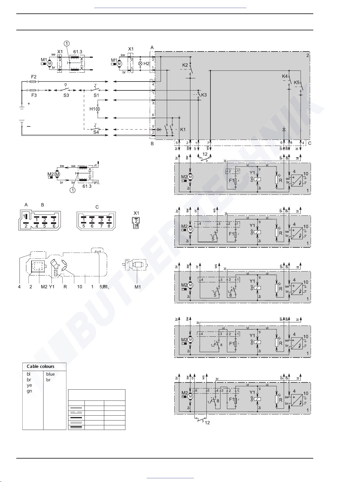
7 Circuit diagrams DBW 160 / 230 (2020) / 300 / 350
704
Fig. 702 (page 1 of 2) Automatic wiring diagram, DBW 230/300 with control unit 1553, 24 volts
bl
br
ye
gn
gr
or
rd
bl
vi
wh
eeelllbbbaaaCCCsssrrruuuooollloooccc
blue
brown
yellow
green
grey
orange
red
black
violet
white
gggnnniiirrriiiWWWsssnnnoooiiitttccceeesss---ssssssooorrrccc
< 7.5 m 7.5 - 15 m
0.75 mm
2
1.0 mm
2
1.5 mm
2
2.5 mm
2
4.0 mm
2
1.5 mm
2
1.5 mm
2
2.5 mm
2
4.0 mm
2
6.0 mm
2
Visit www.butlertechnik.com for more technical information and downloads.
www.butlertechnik.com
Page 43
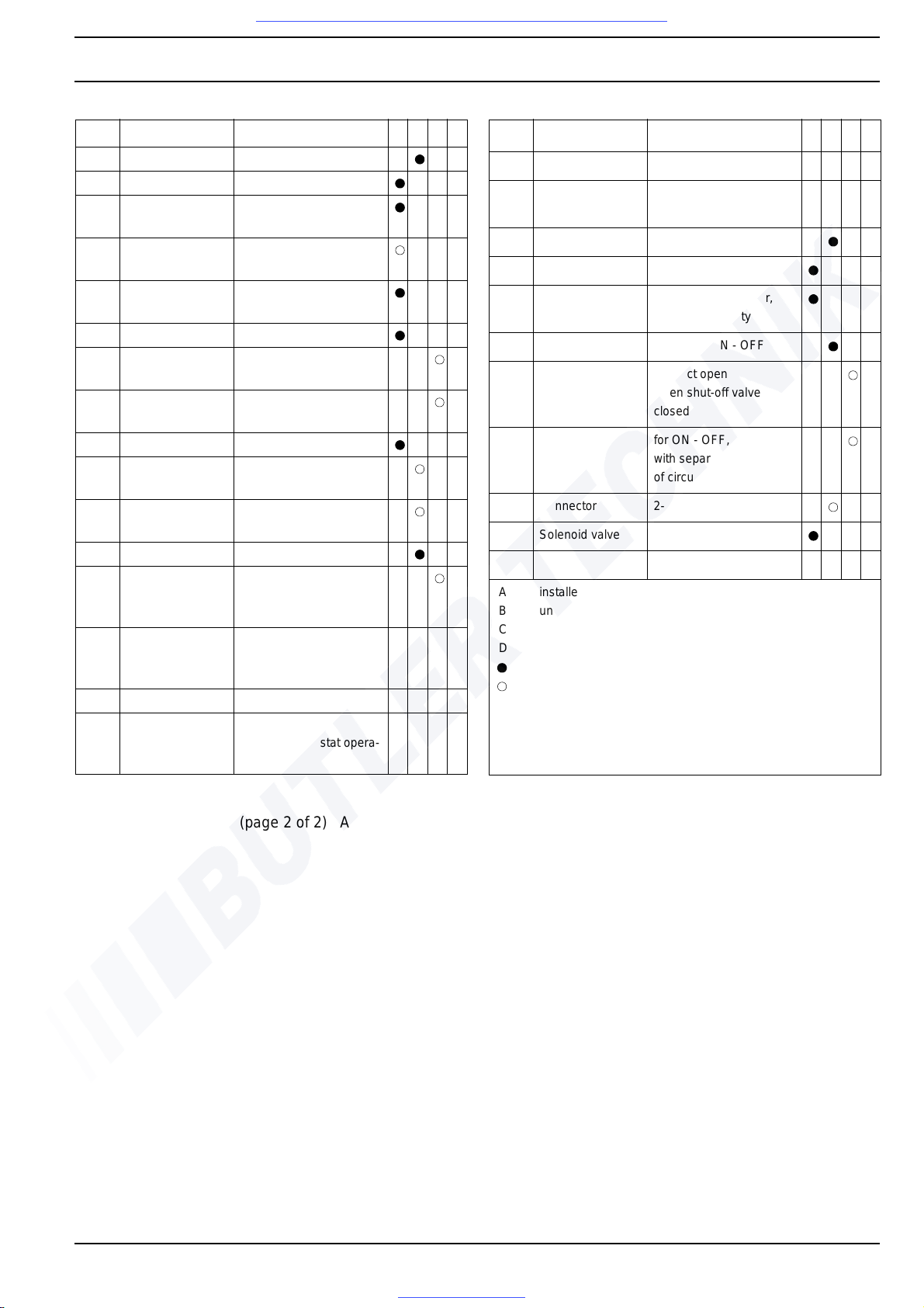
DBW 160 / 230 (2020) / 300 / 350 7 Circuit diagrams
705
Pos. Designation Comment A B C D
1 Heater floating
2 Control unit CU 1553
4 Electronic ignition
unit
5 Thermostat Control thermostat (inter-
nal)
8 Thermostat Temperature-limiter ther-
mostat
10 Ignition electrodes
12 Thermostat Control thermostat (exter-
nal)
61.3 Interference-sup-
pression kit (2 x)
Interference suppression
F1 Thermal fuse reversible polarity
F2 8 A fuse Automotive fuse as per
DIN 72581
F3 8 A fuse Automotive fuse as per
DIN 72581
H1 Light, green Operation indicator
H2 Light,
for circulation
pump
If actuated via S4
K1 Relay Circulation pump;
negative terminal for
heater
K2 Relay Heater motor
K3 Relay Light;
control-thermostat opera-
tion
Pos. Designation Comment A B C D
K4 Relay Electronic ignition unit
K5 Relay Solenoid valve; flame
sensor
M1 Motor Circulation pump
M2 Motor Heater motor
R Flame sensor Photoelectric resistor,
reversible polarity
S1 Switch for heater ON - OFF
S3 Switch
on shut-off valve
Contact open
when shut-off valve
closed
S4 Switch for ON - OFF,
with separate connection
of circulation pump
X1 Connector 2-pin
Y1 Solenoid valve reversible polarity
A
B
C
D
installed in heater
unmounted supply parts
only if required
included in vehicle equipment
fixed allocation
possible depending on the scope of delivery or design type
Ensure good ground connection!
Fig. 702 (page 2 of 2) Automatic wiring diagram, DBW 230/300 with control unit 1553, 24 volts
Visit www.butlertechnik.com for more technical information and downloads.
www.butlertechnik.com
Page 44
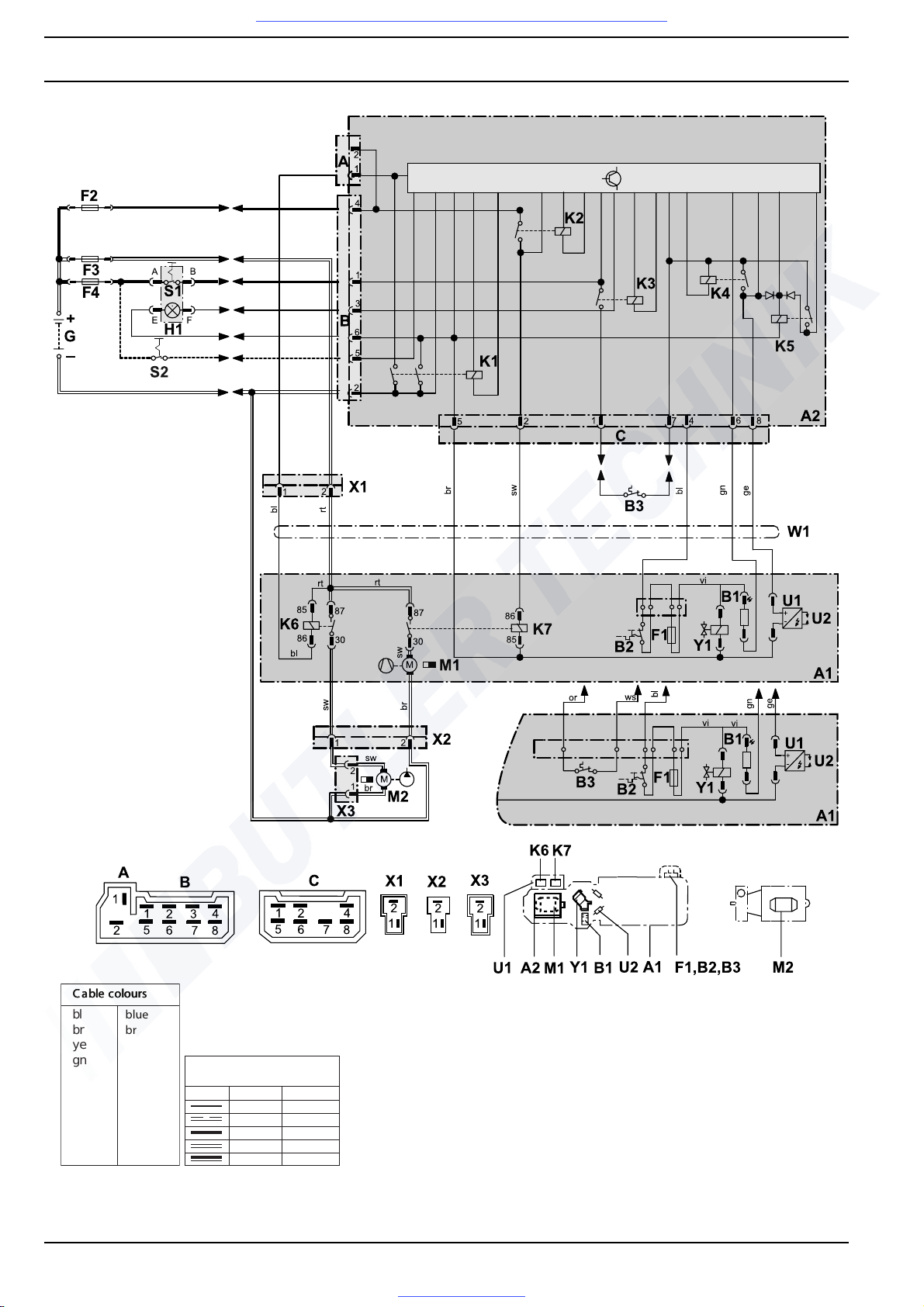
7 Circuit diagrams DBW 160 / 230 (2020) / 300 / 350
706
bl
br
ge
gn
gr
or
rt
sw
vi
ws
Leitungsfarben
blau
braun
gelb
grün
grau
orange
rot
schwarz
violett
weiß
Fig. 703 (page 1 of 2) Automatic wiring diagram, DBW 300/350 with control unit 1553, 24 volts
bl
br
ye
gn
gr
or
rd
bl
vi
wh
eeelllbbbaaaCCCsssrrruuuooollloooccc
blue
brown
yellow
green
grey
orange
red
black
violet
white
gggnnniiirrriiiWWWsssnnnoooiiitttccceeesss---ssssssooorrrccc
< 7.5 m 7.5 - 15 m
0.75 mm
2
1.0 mm
2
1.5 mm
2
2.5 mm
2
4.0 mm
2
1.5 mm
2
1.5 mm
2
2.5 mm
2
4.0 mm
2
6.0 mm
2
Visit www.butlertechnik.com for more technical information and downloads.
www.butlertechnik.com
Page 45
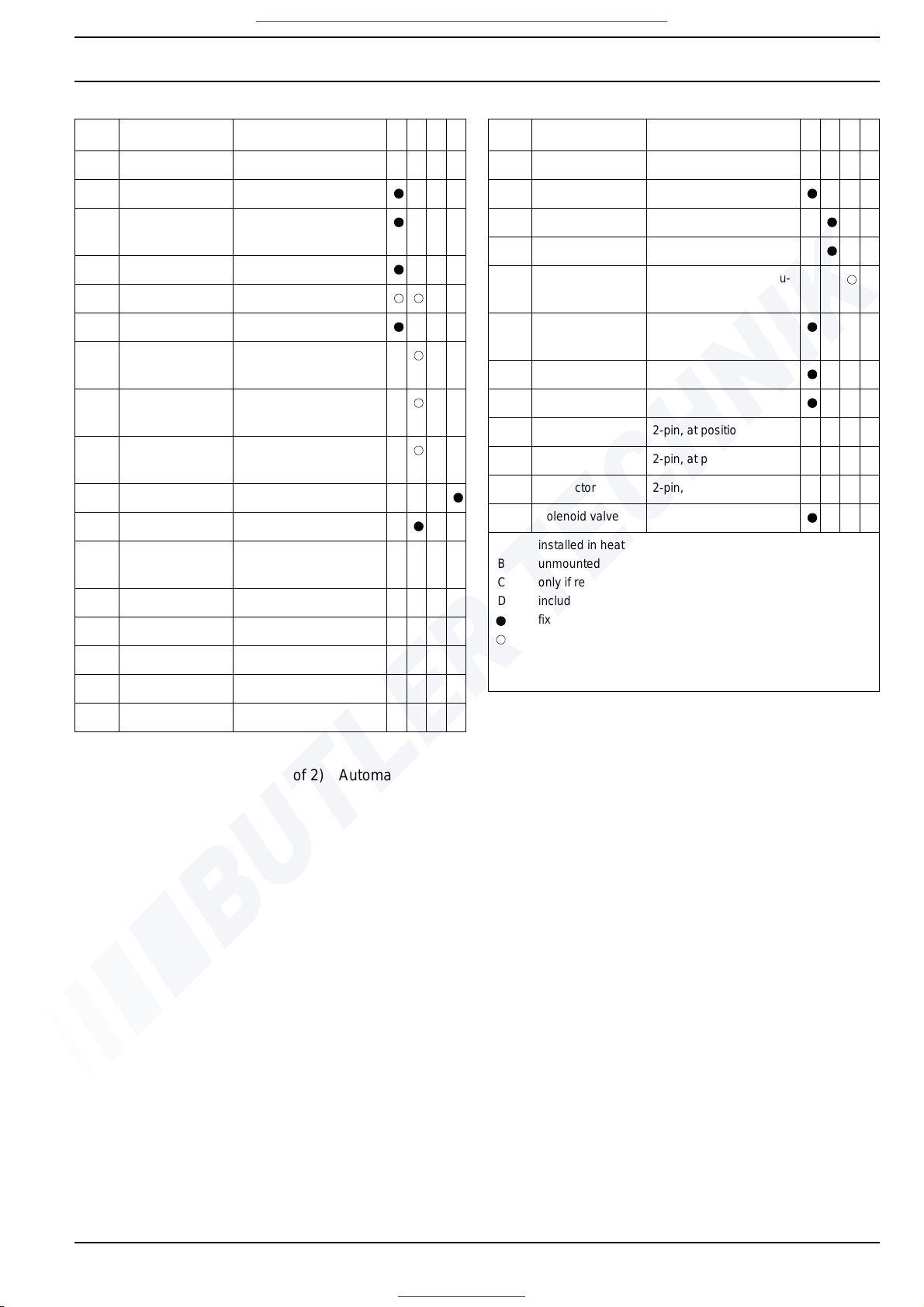
DBW 160 / 230 (2020) / 300 / 350 7 Circuit diagrams
707
Pos. Designation Comment A B C D
A1 Heater floating
A2 Control unit CU 1553
B1 Flame sensor Photoelectric resistor,
reversible polarity
B2 Thermostat Temperature limiter
B3 Thermostat Control thermostat
F1 Thermal fuse reversible polarity
F2 8 A fuse Automotive fuse as per
DIN 72581
F3 16 A fuse Automotive fuse as per
DIN 72581
F4 8 A fuse Automotive fuse as per
DIN 72581
G Battery
H1 Light, green Operation indicator
K1 Relay (in pos. A2) for disconnection of nega-
tive terminal
K2 Relay (in pos. A2) for K7 relay
K3 Relay (in pos. A2) for closed-loop operation
K4 Relay (in pos. A2) for electronic ignition unit
K5 Relay (in pos. A2) for solenoid valve
K6 Relay (in pos. A1) for circulation pump
Pos. Designation Comment A B C D
K7 Relay (in pos. A1) for burner motor
M1 Motor Heater
M2 Motor Circulation pump
S1 Switch for heater ON - OFF
S2 Switch separate switch for circu-
lation pump
U 1 Electronic ignition
unit
U2 Ignition electrodes
W1 Wiring harness
X1 Connector 2-pin, at position of W1
X2 Connector 2-pin, at position of W1
X3 Connector 2-pin, at position of W2
Y1 Solenoid valve reversible polarity
A
B
C
D
installed in heater
unmounted supply parts
only if required
included in vehicle equipment
fixed allocation
possible depending on the scope of delivery or design type
Fig. 703 (page 2 of 2) Automatic wiring diagram, DBW 300/350 with control unit 1553, 24 volts
Visit www.butlertechnik.com for more technical information and downloads.
www.butlertechnik.com
Page 46
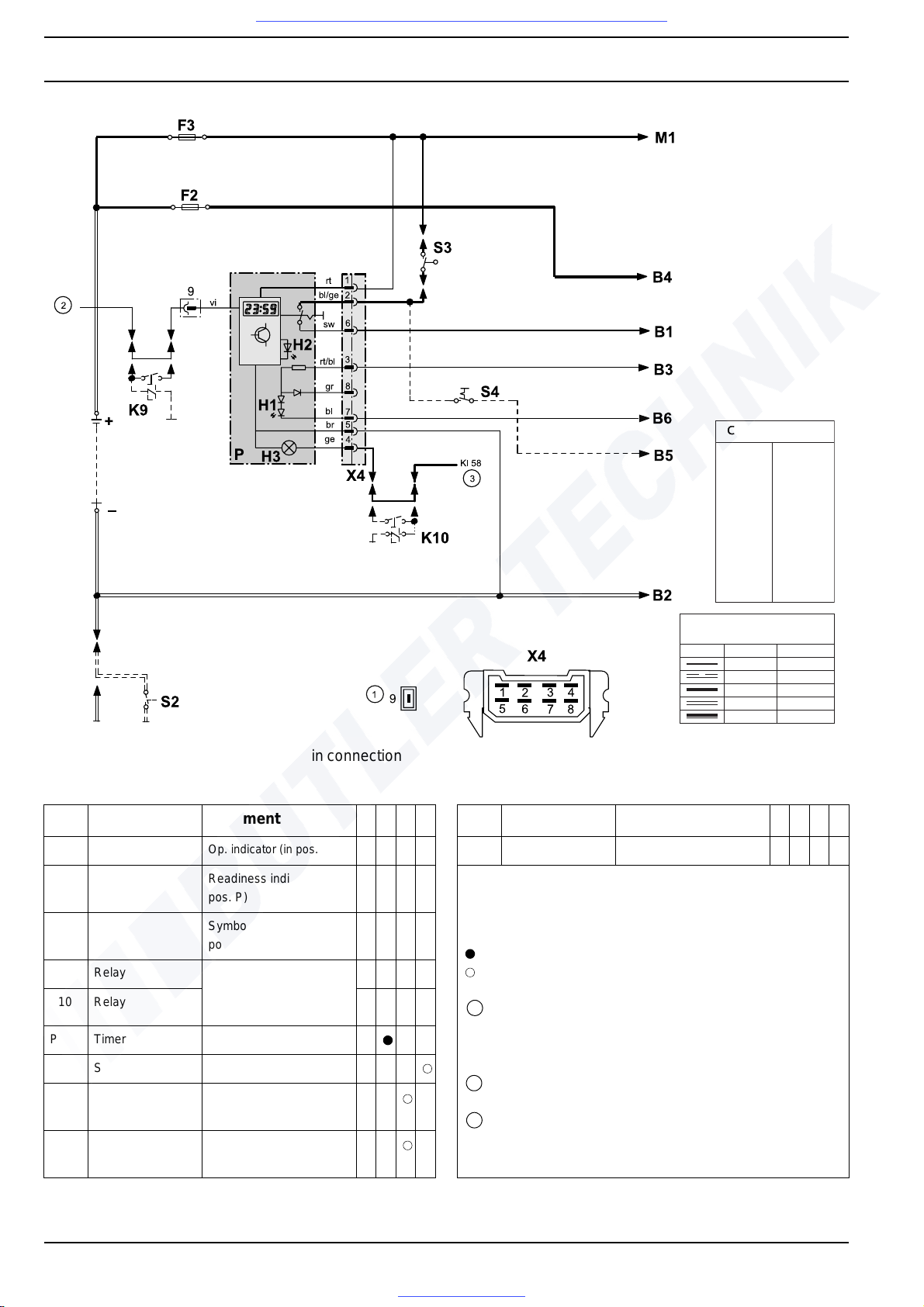
7 Circuit diagrams DBW 160 / 230 (2020) / 300 / 350
708
NOTE: Application example in connection with wiring diagram, fig. 701 or 702.
bl
br
ye
gn
gr
or
rd
bl
vi
wh
eeelllbbbaaaCCCsssrrruuuooollloooccc
blue
brown
yellow
green
grey
orange
red
black
violet
white
gggnnniiirrriiiWWWsssnnnoooiiitttccceeesss---ssssssooorrrccc
< 7.5 m 7.5 - 15 m
0.75 mm
2
1.0 mm
2
1.5 mm
2
2.5 mm
2
4.0 mm
2
1.5 mm
2
1.5 mm
2
2.5 mm
2
4.0 mm
2
6.0 mm
2
Pos. Designation Comment A B C D
H1 LED, green
Op. indicator (in pos. P)
H2 Light-emitting
diode, yellow
Readiness indicator (in
pos. P)
H3 Lights Symbol illumination (in
pos. P)
K9 Relay only required if battery
switch is connected to
negative terminal
K10 Relay
P Timer (digital) for timer operation
S2 Switch Battery switch
S3 Switch
on shut-off valve
Contact open, when shutoff valve closed
S4 Switch (ON - OFF) Separate connection of
circul. pump, ON - OFF
Pos. Designation Comment A B C D
X4 Connector 8-pin (for pos. P)
A
B
C
D
1
2
3
installed in heater
unmounted supply parts
only if required
included in vehicle equipment
fixed allocation
possible depending on the scope of delivery or design type
Timer P:
when plus terminal is connected to connection 9 = continuous
operation during immediate heating
when plus terminal is not connected to connection 9 = 1-hour
heating period
to vehicle terminal 75, if available – otherwise terminal 15
Vehicle illumination (terminal 58)
Fig. 704 Application example for DBW 160/230/300, 12 and 24 volts, operation with timer and
battery switch
Visit www.butlertechnik.com for more technical information and downloads.
www.butlertechnik.com
Page 47
DBW 160 / 230 (2020) / 300 / 350 7 Circuit diagrams
709
Notes
Visit www.butlertechnik.com for more technical information and downloads.
www.butlertechnik.com
Page 48
7 Circuit diagrams DBW 160 / 230 (2020) / 300 / 350
710
Visit www.butlertechnik.com for more technical information and downloads.
www.butlertechnik.com
Page 49
DBW 160 / 230 (2020) / 300 / 350 8 Service and Maintenance
801
8 Service and Maintenance
8.1 General
This section describes permissible service work on installed heater systems.
8.2 Heater servicing
As long as the heater is in operation or in run-down mode,
the battery main power supply must not be disconnected
to prevent the heater from overheating and, as a result,
the overheat protection from being triggered.
When extensive repair work is carried out, it is advisable
to remove the heater.
When work on the heating circuit has been carried out, a
coolant mixture consisting of water and anti-freeze agent
must be refilled according to the manufacturer's instructions and the heating circuit must be bled.
8.3 Vehicle servicing
CAUTION
In the vicinity of the heater, a temperature of
85° C must by no means be exceeded (e.g. when paint
work is carried out on the vehicle).
8.4 Heater test run
The heater must not, not even with a timer, be operated in
enclosed rooms such as garages or workshops without
exhaust-gas extraction systems.
8.5 Maintenance work
To ensure the functional reliability of the heater, the following maintenance work must be performed:
• The openings of the combustion air intake line an d the
exhaust outlet must be checked for soiling and
cleaned.
• Outside the heating period, the heater must be oper-
ated with a cold vehicle engine every 4 weeks for 10
minutes, with the heating temperature set to "warm".
This helps to prevent difficulties during start-up.
• When replacing the coolant for the vehicle engine,
take care to bleed the heater and the circulation pump
properly after the vehicle cooling system has be en
bled.
Refill coolant as specified by the vehicle manufacturer.
• At least once a year, with heavily contaminated fuel
more often, the fuel filter or the filter insert must be replaced to prevent malfunctions.
• When leakage occurs, the fuel pump and the fuel lines
must be replaced immediately, otherwise every 5
years.
• The heater should be checked by a Spheros service
workshop at regular intervals, at the latest at the beginning of a heating period.
Visit www.butlertechnik.com for more technical information and downloads.
www.butlertechnik.com
Page 50
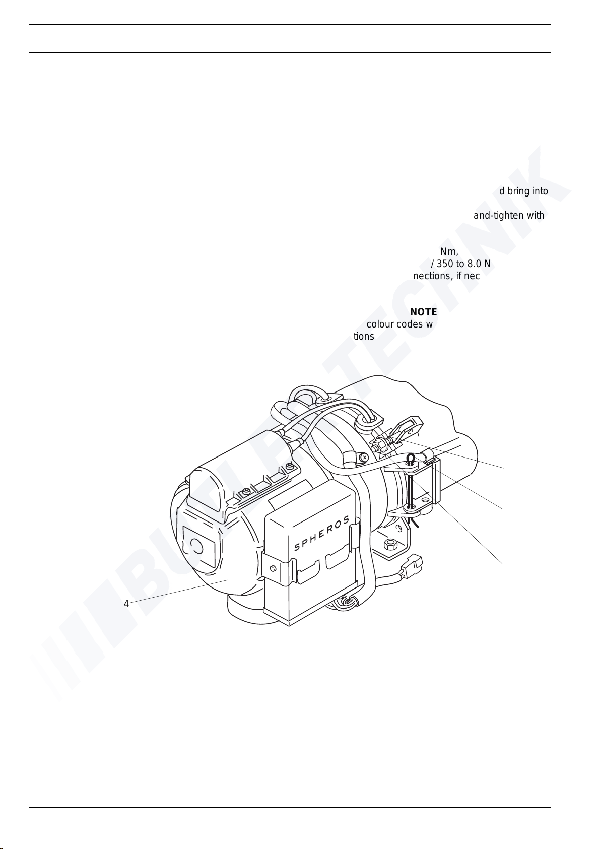
8 Service and Maintenance DBW 160 / 230 (2020) / 300 / 350
802
8.5.1 Swinging the burner head open and
closed
DANGER
The electronic ignition unit is operated at high voltage.
Danger! Ensure that the wiring harness connectors are
disconnected from the control unit before swinging open
the burner head.
Reconnect the connectors once the burner head is swung
closed again.
NOTE
The heater is maintenance-friendly. Swinging the burner
head
1
) open grants access to the following components:
– Fuel pump and atomiser nozzle
– Solenoid valve
– Electronic ignition unit
– Ignition electrodes
– Flame sensor
– Combustion chamber
– Nozzle-block preheater (if installed)
– In DBW 160, ensure correct fit of the cable grommets
To achieve the required opening angle, the electrical con-
nections may have to be disconnected.
Swinging the burner head open
1. Disconnect electrica l connections, if necessary.
2. Loosen nuts (3, Fig. 801) un til bolts (1) can be swung
out.
3. Swing bolts (1) out.
4. Swing burner head (4) open.
Swinging the burner head closed
1. Swing burner hea d (4, Fig. 801) closed and bring into
assembly position.
2. Swing bolts (1) closed and initially hand-tighten with
nuts (3) to prevent stress.
3. Torque nuts (3)
- in DBW 160 to 5.0 Nm + 1 Nm,
- in DBW 230(2020) / 300 / 350 to 8.0 Nm +/- 10%.
4. Connect electrical connections, if necessary.
NOTE
Observe wiring colour codes when reconnecting the electrical connections
.
Fig. 801 Swinging the burner head open and closed
1 bolt (2)
2 split pin
3 nut (2)
4 burner head
1
2
3
4
NOTE
• Depending on the swing direction of the burner
head
1
), the split pin can be located on the other side.
• The illustration shows the burner head of the
DBW 160 series heaters.
1
) not possible with design type DBW 300.62
Visit www.butlertechnik.com for more technical information and downloads.
www.butlertechnik.com
Page 51
DBW 160 / 230 (2020) / 300 / 350 8 Service and Maintenance
803
8.6 Visual inspections /
installation instructions
8.6.1 Connection to the vehicle's cooling
system
The heater must be connected to the vehicle's cooling
system as illustrated in Fig. 802. The minimum amount of
coolant required in the circuit is 10 litres.
As a rule, the coolant hoses supplied by Spheros must be
used. Otherwise, hoses in compliance with DIN 73411 or
better must be used. The hoses must be routed without
any kinks and - to ensure proper bleeding of the heater in an upward pitch, if possible. Hose connections must be
secured with clamps against slipping off.
NOTE:
The tightening torques of the hose clamps used must be
observed.
In the vehicle's cooling system or a separate heating circuit, only pressure-relief valves with an opening pressure
of min. 0.4 bar and max. 2.0 bar may be used.
Prior to initial start-up of the heater or after replacement of
the coolant, proper bleeding of the cooling system must
be ensured. Heater and lines must be installed to en su re
static bleeding of the system.
Proper bleeding can be identified by almost noise-free op-
eration of the circulation pump. Poor bleeding may result
in the tripping of the resettable temperature limiter or the
thermal fuse while the heater is in operation.
When circulation pump U 4855 / Aquavent 6000C is used,
a low coolant level or a blocked pump impeller will cause
the circulation pump to be shut off automatically approx.
15 seconds after activation. The circulation pump can be
restarted after approx. 2 minutes.
When circulation pump U 4856 / Aquavent 6000SC is
used, a low coolant level or a blocked pump impeller will
cause the circulation pump to be shut off autom atica lly
approx. 45 seconds after activation. The circulation pump
can be restarted after approx. 2 minutes.
8.6.2 Connection to the vehicle's fuel system
Fuel is taken from the vehicle's fuel tank or a separate fuel
tank.
8.6.2.1 Fuel lines
To prevent trapped air, fuel lines must be routed in an
upward pitch, if possible. Connections within the fuel lines
must be secured by hose clamps unless mechanical
threaded joints are used.
If fuel hoses are used, only the hoses supplied or offe red
by Spheros must be used. Any other fuel hose must
comply with DIN 73379 as a minimum. Fuel hoses must
neither be kinked nor twisted and must be fastened with
clamps at intervals of approx. 25 cm.
Materials commonly used in vehicle construction may
also be used as fuel lines, taking into account the respective joining techniques.
As a rule, the following points must be observed when
routing fuel lines:
• Lines must be protected against heat
DANGER
When the system overheats, the outer shell of the heater
can reach the ignition temperature of diesel fuel!
• Lines must be protected against stone chipping
• Dripping or evaporating fuel may neither collect
nor be ignited by hot components or electrical
equipment.
It is not permissible to install a shut-off device in the return
line!
CAUTION
Operating the heater with closed return line will result in
damage to the fuel pump. Fuel may escape. Fire hazard.
Freely suspended lines must be secured to prevent them
from sagging.
It is not permissible to install an additional fuel pump.
See Section 1, Page 102. for legal re qu ire m en ts.
Visit www.butlertechnik.com for more technical information and downloads.
www.butlertechnik.com
Page 52
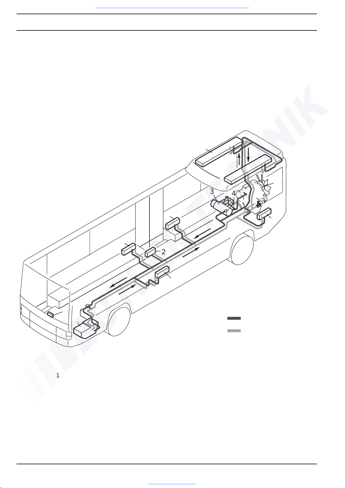
8 Service and Maintenance DBW 160 / 230 (2020) / 300 / 350
804
Fig. 802 Example of heater installation in a bus
4
8
3
1
1
1
1
2
7
5
6
Coolant heating circuit –
Wall heater and roof-duct heating system
1 Wall heater with fan
2 Heat exchanger at entry point
3 Heater
4 Circulation pump
5 Heat exchanger in roof area
6 Vehicle engine
7 Heater in driver area
8 Control element
Supply
Return
Visit www.butlertechnik.com for more technical information and downloads.
www.butlertechnik.com
Page 53
DBW 160 / 230 (2020) / 300 / 350 8 Service and Maintenance
805
Permissible fuel-line dimensions:
• Inside diameter for suction and return lines: 6 mm
(other diameters upon request).
• Max. permissible line length per suction and return
line: 10 m
• Max. permissible suction height: 2 m
• Max. permissible supply pressure: 0.3 bar.
8.6.2.2 Fuel filter
Fuel filters supplied or approved by Spheros must be installed (observe flow direction). To avoid malfunctions,
the filter or filter insert must be replaced before the beginning of each heating period.
8.6.3 Combustion air supply
Combustion air may by no means be extracted from
spaces in which persons are present. The combustion air
intake opening may not point in the direction of trav el. It
must be positioned in a location where it cannot become
clogged with soil or snow and draw in splash water.
The combustion air inlet must not be positioned above the
exhaust-gas outlet.
When the heater is installed in a joint installation space
near the vehicle's fuel tank, combustion air must be drawn
in from outside the vehicle and the exhaust gas must be
routed to the outside. Lead-through openings must be
protected against splash.
If the heater is placed in an enclosed installation case, a
ventilation opening is required:
DBW 160 / 230 / 300 30 cm
2
DBW 350 35 cm
2
If the temperature in the installation case exceeds the permissible ambient temperature of the heater (see technical
data), the ventilation opening must be enlarged after prior
consultation with Spheros.
8.6.4 Exhaust pipe
The exhaust-pipe end may not point in the direction of
travel.
The exhaust-pipe end must be positioned in a location
where it cannot become clogged with soil or snow.
Only rigid pipes made of unalloyed or alloyed steel with a
minimum wall thickness of 1.0 mm or flexible pipes of
alloyed steel must be used as exhaust pipes. The exhaust
pipe must be fastened to the heater e.g. by means of a
clamp. See legal requirements for further specifications.
Permissible exhaust-pipe dimensions:
– Inner diameter:
DBW 160: 38 mm
DBW 230 to .32 / DBW 300 to .15: 80 mm
DBW 230 from .33 / DBW 300 from .16: 70 mm
DBW 350 70 mm
– Max. permissible line length:
5 m without combustion air intake extension
– Total length of combustion air inta ke and exhaust pipe
max. 5 m
– Max. permissible bending: 270°
NOTE
If the exhaust pipe is routed near temperature-sensitive
components it must be insulated!
Alternatively, an exhaust-gas bypass approved by
Spheros must be installed.
Visit www.butlertechnik.com for more technical information and downloads.
www.butlertechnik.com
Page 54
8 Service and Maintenance DBW 160 / 230 (2020) / 300 / 350
806
8.7 Removal and installation
CAUTION
When the heater is installed, only the following disassembly or removal processes are permitted, provided there is
sufficient space for removal:
– Replacing the temperature limiter
– Replacing the fan or control thermostat
– Replacing the thermal fuse
– Replacing the fusible link
– Replacing the burner head
– Replacing the electronic ignition unit
– Replacing the flame sensor
– Replacing the combustion chamber
8.7.1 Heater, removal and installation
8.7.1.1 Removal
1. Disconnect wiring-harness connector from control
unit.
2. Remove clamp at exhaust-gas outlet.
3. Remove fuel supply and return line and fuel lines and
close with blanking plugs.
Close shut-off valves, if present.
4. Loosen hose clamps at the coolant hoses, pull off
hoses and close with blanking plugs.
5. Remove relevant fasteners (bolts, nuts, washers) at
the support.
6. Remove heater.
8.7.1.2 Installation
1. Place heater in installation position and fasten with
relevant bolts, washers and nuts.
2. Secure line at exhaust-gas outlet with clamp.
3. Slide on coolant hoses and secure with hose clamps.
Open shut-off valves.
4. Slide on fuel supply and return lines and secur e.
5. Connect wiring-harness connector to control unit.
6. Bleed fuel-supply system.
7. Bleed coolant circuit.
8.7.2 Replacing the temperature limiter
NOTE
The procedure for replacing the temperature limiter is the
same for installed or uninstalled heaters.
For replacement process, see 9.2.1.
8.7.3 Replacing the control thermostat
NOTE
The procedure for replacing the contro l ther m os tat is the
same for installed or uninstalled heaters.
For replacement process, see 9.2.2.
8.7.4 Replacing the fan thermostat
NOTE
The procedure for replacing the fan ther mo sta t is the
same for installed or uninstalled heaters.
For replacement process, see 9.2.3.
8.7.5 Replacing the thermal fuse
NOTE
The procedure for replacing the thermal fu se is the sa me
for installed or uninstalled heaters.
For replacement process, see 9.2.4.
8.7.6- Replacing the burner head
NOTE
The procedure for replacing the burner head is the same
for installed or uninstalled heaters.
For replacement process, see 9.2.6.
DANGER
The electronic ignition unit is operated at high voltage.
Danger! Ensure that the wiring harness connectors are
disconnected from the control unit before replacing the
burner head.
8.7.7 Replacing the electronic ignition unit
NOTE
The procedure for replacing the electro nic ign itio n un it is
the same for installed or uninstalled heaters.
For replacement process, see 9.2.10.
DANGER
The electronic ignition unit is operated at high voltage.
Danger! Ensure that the wiring harness connectors are
disconnected from the control unit before replacing the
electronic ignition unit.
8.7.8 Replacing the flame sensor
NOTE
The procedure for replacing the flame se nsor is the same
for installed or uninstalled heaters.
For replacement process, see 9.2.11.
DANGER
The electronic ignition unit is operated at high voltage.
Danger! Ensure that the wiring harness connectors are
disconnected from the control unit before replacing the
flame sensor.
Visit www.butlertechnik.com for more technical information and downloads.
www.butlertechnik.com
Page 55
DBW 160 / 230 (2020) / 300 / 350 8 Service and Maintenance
807
8.7.9 Replacing the combustion chamber
NOTE
The procedure for replacing the combustion chamber is
the same for installed or uninstalled heaters.
For replacement process, see 9.2.15.
DANGER
The heater is operated with high voltage. Danger! Ensure
that the wiring harness connectors are disconnected from
the control unit before replacing the combustion chamber.
Visit www.butlertechnik.com for more technical information and downloads.
www.butlertechnik.com
Page 56
8 Service and Maintenance DBW 160 / 230 (2020) / 300 / 350
808
8.8 Start-up
After installation of the heater, the coolant circuit and the
fuel-supply system must be carefully bled. The vehicle
manufacturer's instructions must be observed during the
procedure. During the test run, all coolant and fuel connections must be checked for sealing tightness and firm
fit. Should the heater switch into malfunction mode during
operation, troubleshooting must be performed (see
Section 5).
8.8.1 Bleeding the coolant circuit
NOTE
Bleeding must always be performed in accordance with
the manufacturer's instructions. The circulation pump
must not be switched on for the bleeding process.
Set the vehicle heating system to "warm" and refill coolant
which must consist of a mixture of water and at least 10 %
anti-freeze agent (on glycol basis) (corrosion protection).
The use of pure water will not provide any corrosion protection and, due to the lower boiling point of water, may
result in a partial loss of coolant in the event of overheating, requiring coolant to be refilled. Only coolant additives
may be used that are not aggressive against metals, plastics and rubber and that do not cause any deposits.
Run the vehicle engine at high idle until the cooler thermo-
stat is open. Shut off vehicle engine and check coolant
level, refill coolant, if required.
Switch on the heater and the vehicle's heate r fan while the
vehicle engine is shut off. After a certain cooling period,
the heater must automatically start and then shut itself
down again. If no restart occurs, the temperature limiter
on the heater was tripped because the heater has not
been bled properly. Reset temperature limiter (by pushing
the button on the temperature limiter) and repeat complete bleeding procedure.
NOTE
The heater can be equipped with an automatically resetting temperature limiter. In this case manual reset is not
applicable.
8.8.2 Bleeding the fuel-supply system
When the heater is switched on, the fuel pump draws in
fuel, filling the heater's entire fuel supply system.
If no combustion occurs after the first start-up, the heater
must be switched off and switched on again.
Visit www.butlertechnik.com for more technical information and downloads.
www.butlertechnik.com
Page 57
DBW 160 / 230 (2020) / 300 / 350 9Repair
901
9 Repair
9.1 General
This section describes permissible repair work on uninstalled heater systems. Any further disassembly will void
the warranty.
For re-assembly, only spare parts from the corresponding
spare-parts kits must be used.
DANGER
The electronic ignition unit is operated at high voltage.
The following components may also be replaced when the
heater is installed, provided sufficient space is available.
– Temperature limiter
– Fan or control thermostat
– Thermal fuse
– Burner head
– Electronic ignition unit
– Flame sensor
– Combustion chamber.
Danger! Ensure that the wiring harness connectors are
disconnected from the control unit before replacing a com ponent.
Visit www.butlertechnik.com for more technical information and downloads.
www.butlertechnik.com
Page 58
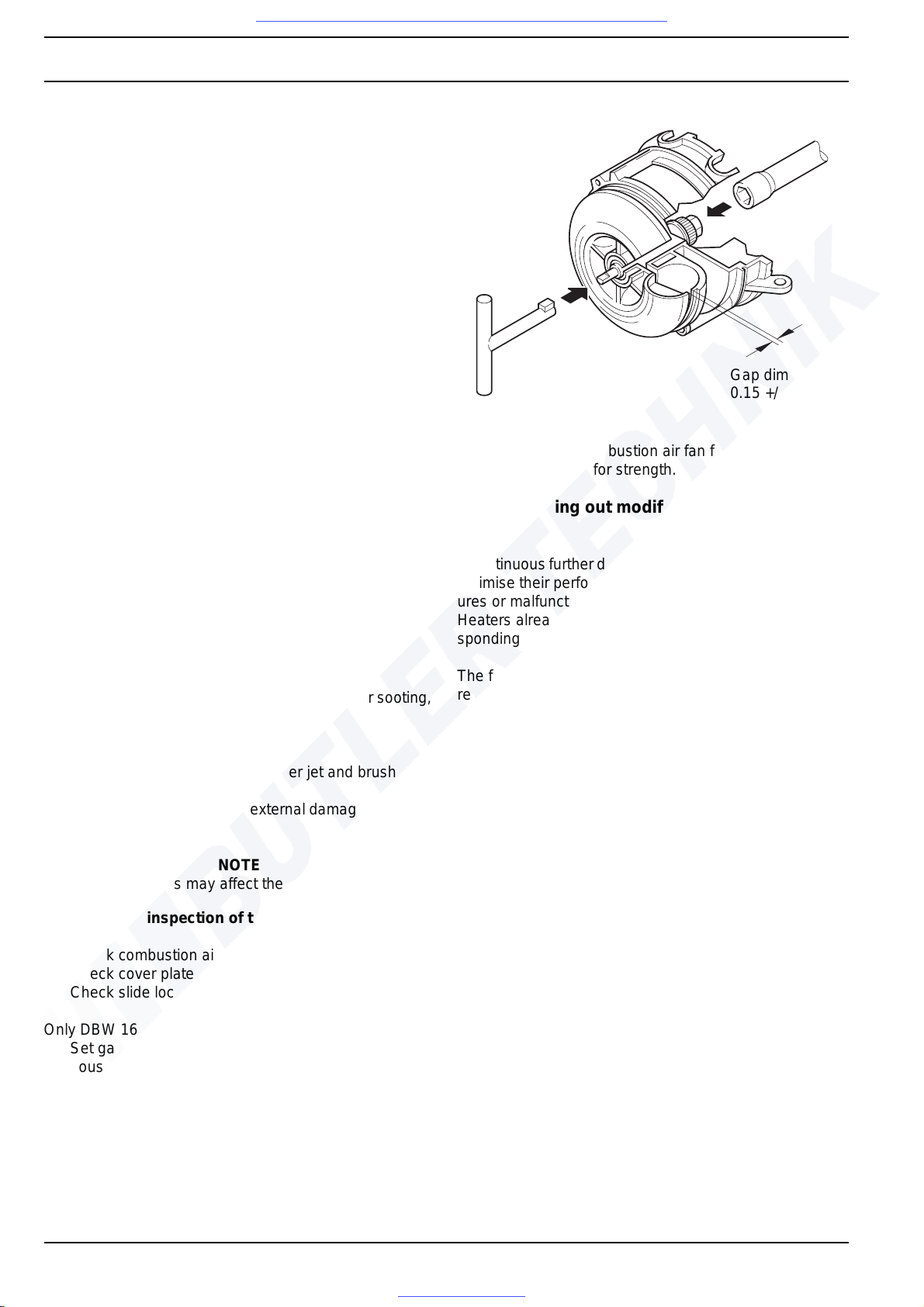
9Repair DBW 160 / 230 (2020) / 300 / 350
902
9.1.1 Measures on components in
disassembled condition
CAUTION
All seals and gaskets located between disassem bl ed
components must always be discarded and replaced.
9.1.1.1 General visual inspection
• Check all components for damage (cracks, deformation, wear etc.) and replace if required.
• Check connectors and lines for corrosion, loose contacts, crimping faults etc. and repair if required.
• Check connectors for corrosion and contacts for firm
fit, replace if required.
9.1.1.2 Visual inspection of the combustion chamber
NOTE
DBW 300.62 is not provided with a flame pipe
– Check swirler for firm fit.
– Check combustion chamber for scaling and remove
carbon deposits, if necessary.
– Check weld seam for cracks.
NOTE
Cracks on the weld seam of up to approx. 80 mm in longitudinal direction are permissible.
9.1.1.3 Visual inspection of the heat exchanger
– Check exhaust ducting in heat exchanger for sooting,
deposits, damage and corrosion.
NOTE
Deposits must be removed with water jet and brush.
– Check heat exchanger for external damage, deforma-
tions etc.
NOTE
Heavy deformations may affect the coolant flow.
9.1.1.4 Visual inspe ction of the combustion air fan
– Check combustion air fan for soiling and cracks.
– Check cover plate for firm fit.
– Check slide lock for firm fit.
Only DBW 160:
– Set gap dimension between fan wheel and fan
housing (can be measured with a feeler gauge) at the
narrowest point to 0.15 +/- 0.05 mm.
For suitable tool, see spare-parts lists and accessories catalogue.
Only DBW 230/300/350:
Check hub of the combustion air fan for cracks, check
shroud (rear panel) for strength.
9.1.2 Carrying out modifications
NOTE
A continuous further development of the heaters serves to
optimise their performance with the aim of preventing failures or malfunctions.
Heaters already in use may usually be upgraded. Corresponding modification kits are available for this purpose.
The following modifications can be carried out as part of
repair work:
• Installation of the nozzle-block preheaters for DBW
160 /230 / 300 / 350 with control unit 1553 (see
9.1.2.1).
Gap dimension
0.15 +/- 0.05
Special tool
DBW 160
Visit www.butlertechnik.com for more technical information and downloads.
www.butlertechnik.com
Page 59
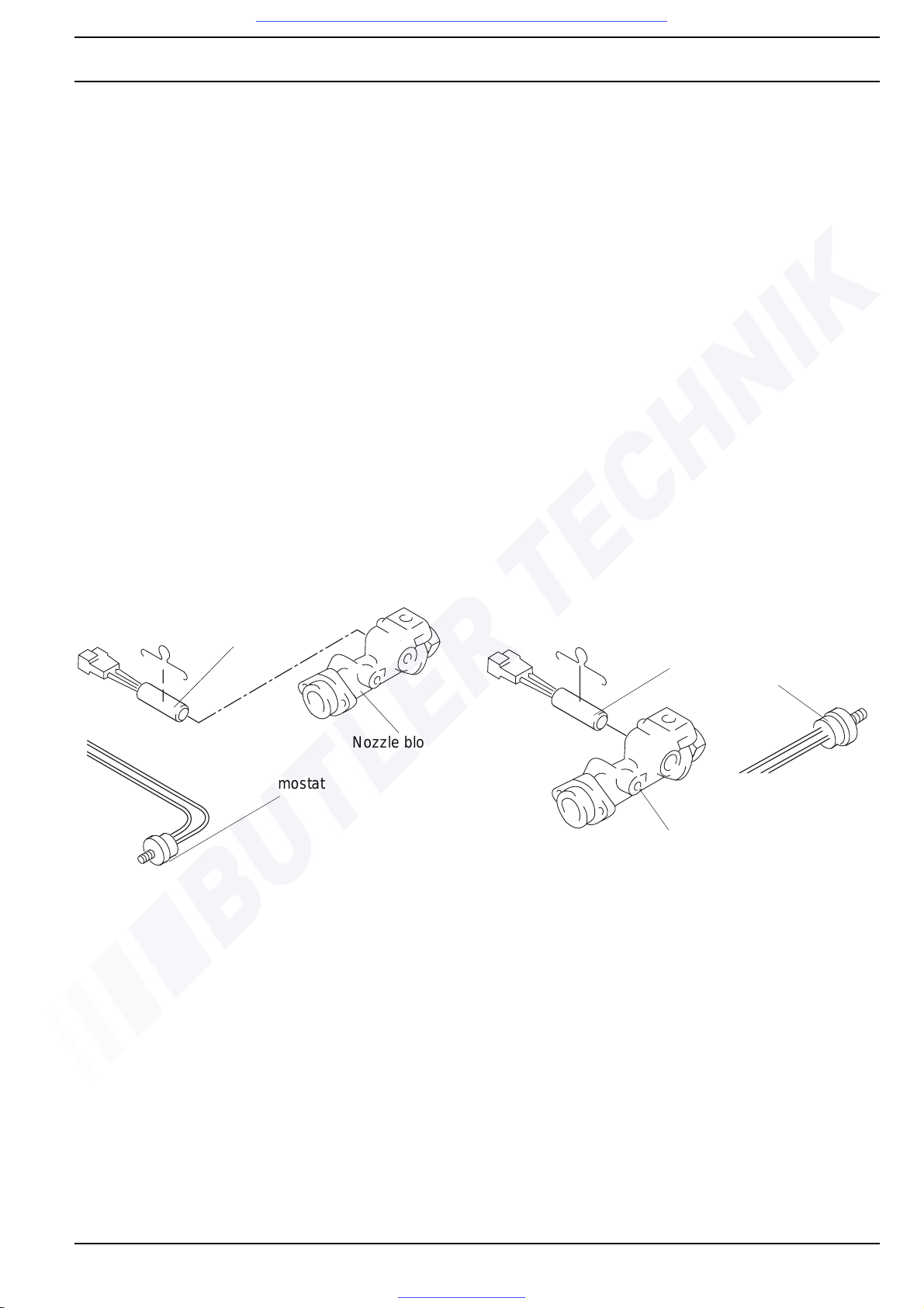
DBW 160 / 230 (2020) / 300 / 350 9Repair
903
9.1.2.1 Installation of the nozzle-block preheater
General
The nozzle-block preheater serves to heat the fuel flowing
to the atomiser nozzle. At extremely low temperatures,
malfunctions may occur in the above mentioned heaters if
they are not equipped with nozzle-block preheaters.
At a temperature of < 0° C, the heating element in the
nozzle block is actuated via a thermostat. The heating du ration depends on the heat reflected in the combustion
chamber and the heater switches off when the temperature at the thermostat is +8° C .
If no nozzle-block preheater is installed in the heater, it
can be retrofitted according to the following procedure.
The following spare-parts kits for the heaters listed above
are available for retrofits:
• 12 V heaters with control unit 1553,
order no. 968 89A
• 24 V heaters with control unit 1553,
order no. 989 71A
The spare-parts kit includes the following parts:
1 heating element
1 retaining clamp
1 relay
1 thermostat
1 wiring harness
1 tab
1 disk
1 nut
1 serrated lock washer
1 connector housing, 4-pin
1 connector housing, 2-pin
4 female disconnects
Heating element
Nozzle block
Thermostat
DBW 160
Heating element
Thermostat
Nozzle block
DBW 230 / 300 / 350
Visit www.butlertechnik.com for more technical information and downloads.
www.butlertechnik.com
Page 60
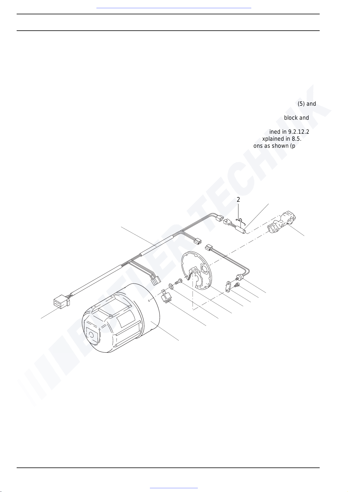
9Repair DBW 160 / 230 (2020) / 300 / 350
904
Implementation with DBW 160
NOTE
With DBW 160 heaters, the disk and the nut in the
retrofit kit are not required.
1. Swing burner head open as explained in 8.5.1.
2. Remove ignition electrodes as explained in 9.2.12.1.
3. Remove circlip and pull disk with flame sensor off
nozzle block.
4. Fasten ther mostat (5) to the nozzle-block plate by
means of the tab (7) and bolt (6).
5. Insert heating element (3) into the nozzle block (4)
and fasten with retaining clamp (2).
6. Fasten relay (11) to the protective cap of the burner
head (12) using a screw (9) and serrated lock washer
(10).
NOTE
The polarity in the following work step is not important.
7. Snap female disconnects into the 2-pin connector
housing to connect the heating element.
NOTE
Route wiring harness (1) behind the solenoid valve
and route to outside via a rubber grommet with
2-pin connector housing.
8. Establish electrical connections between wiring
harness (1), heating element (3), thermo st at (5 ) an d
relay (11).
9. Place disk with flame sensor on nozzle block and
secure with circlip.
10. Install ignition electrodes as explained in 9.2.12.2.
11. Swing burner head closed as explained in 8.5.1.
12. Establish electrical connections as shown (page 904).
Retrofitting DBW 160
1
2
3
4*
5
6*
7
8*
9*
10
11
12*
X1 connector
1 wiring harness
2 retaining clamp
3 heating element
4 nozzle block *
5 thermostat
6bolt *
07tab
08 nozzle-block plate *
09 screw *
10 serrated lock washer
11 relay
12 protective cap of burner head *
* not included in spare-parts kit
Visit www.butlertechnik.com for more technical information and downloads.
www.butlertechnik.com
Page 61
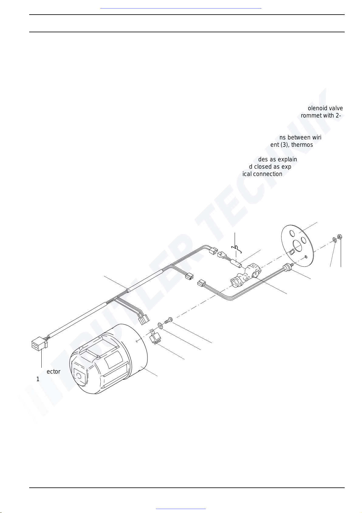
DBW 160 / 230 (2020) / 300 / 350 9Repair
905
Implementation with DBW 230/300/350
NOTE
• With DBW 230 / 300 heaters, the tab in the retrofit kit
is not required.
1. Swing burner head open as explained in 8.5.1.
2. Remove ignition electrodes as explained in 9.2.12.1.
3. Unscrew flame sensor from di sk as explained in
9.2.11.1.
4. Remove circlip and pull current disk with flame sensor
off nozzle block and discard.
5. Insert heating element (3) into the nozzle block (8)
and fasten with retaining clamp (2).
6. Place disk ( 4) on nozzle b l ock and secure with circlip.
7. Fasten thermostat (7) to disk ( 4) by means of serrated
lock washer (5) and nut (6).
8. Install flame sensor as exp lained in 9.2.13.2.
9. Fasten relay (11) to the protective cap of the burner
head (12) using a screw (9) and serrated lock washer
(10).
NOTE
The polarity in the following work step is not important.
10. Make female disconnects for connection of
heating element snap into the 2-pin connector
housing.
NOTE
Route wiring harness (1) behind the solenoi d valve
and route to outside via a rubber grommet with 2-
pin connector housing.
11. Establish electrical connections between wiring
harness (1), heating element (3), thermostat (7) and
relay (11).
12. Install ignition electrodes as explained in 9.2.12.2.
13. Swing burner head closed as explained in 8.5.1.
14. Establish electrical connections as shown (page 905).
Retrofitting DBW 230 / 300 / 350
5
7
8*
9*
10*
11
12*
1
2
3
Connector
X1
4
6
01 wiring harness
02 retaining clamp
03 heating element
04disk
05 serrated lock washer
06nut
07 thermostat
08 no zz le blo ck *
09 screw *
10 serrated lock washer *
11 relay
12 protective cap of burner head *
* not part of scope of supply
* of spare-parts kit
Visit www.butlertechnik.com for more technical information and downloads.
www.butlertechnik.com
Page 62
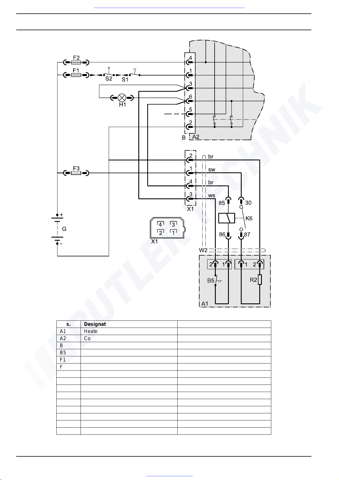
9Repair DBW 160 / 230 (2020) / 300 / 350
906
Electrical connection
Pos. Designation Comment
A1 Heater
A2 Control unit CU 1553
B Connector, 6-pin
B5 Thermostat for nozzle-block preheating
F1 Fuse Flat fuse as per DIN 72581
F2 Fuse Flat fuse as per DIN 72581
F3 16 A (12 V); 8 A (24 V) fuse Flat fuse as per DIN 72581
G Battery
H1 Light Operating indicator
K6 Relay for nozzle-block preheating
R2 Heating element for nozzle-block preheating
S1 Switch On / Off
S2 Switch at shut-off valve
W2 Wiring harness
X1 Connector, 4-pin
Visit www.butlertechnik.com for more technical information and downloads.
www.butlertechnik.com
Page 63
DBW 160 / 230 (2020) / 300 / 350 9Repair
Visit www.butlertechnik.com for more technical information and downloads.
www.butlertechnik.com
9.2 Disassembly and assembly
9.2.1 Replacing the temperature limiter
9.2.1.1 Removal
1. If required, Remove nut (4, Fig. 901) and take off
protective cap (3).
2. Disconnect electrical connection to temperature
limiter (8).
3. Unscrew temperature limiter (8) from angular bracket
(5) or unscrew and remove hexagon head plug (6).
4. Carry out measures on components in disassembled
state (see 9.1.1).
9.2.1.2 Installation
1. Screw temperature limiter (8, Fig. 901) by hand into
the angular bracket (5) or into the hexagon head
plug (6).
2. Establish electrical connection.
3. If required, attach protective cap (3) and secure with
nut (4).
9.2.2 Replacing the control thermostat
9.2.2.1 Removal
1. Remove nut (4, Fig. 901) and ta ke off protective
cap (3).
2. Disconnect electrical connecti on to control thermostat
(1) at connecting block (2).
3. Unscrew control thermostat (1) from angular bracket
(5) or heat exchanger (10) and remove.
4. Carry out me asures on compo nents in disassemb led
condition (see 9.1.1).
9.2.2.2 Installation
1. Screw control thermostat (1, Fig. 901) manually into
angular bracket (5) or heat exchanger (10).
NOTE
Tighten control thermostat hand-tight
when installing it into the heat exchanger.
2. Establish electrical connection.
3. Attach protective cap (3) and secure with nut (4).
907
Page 64
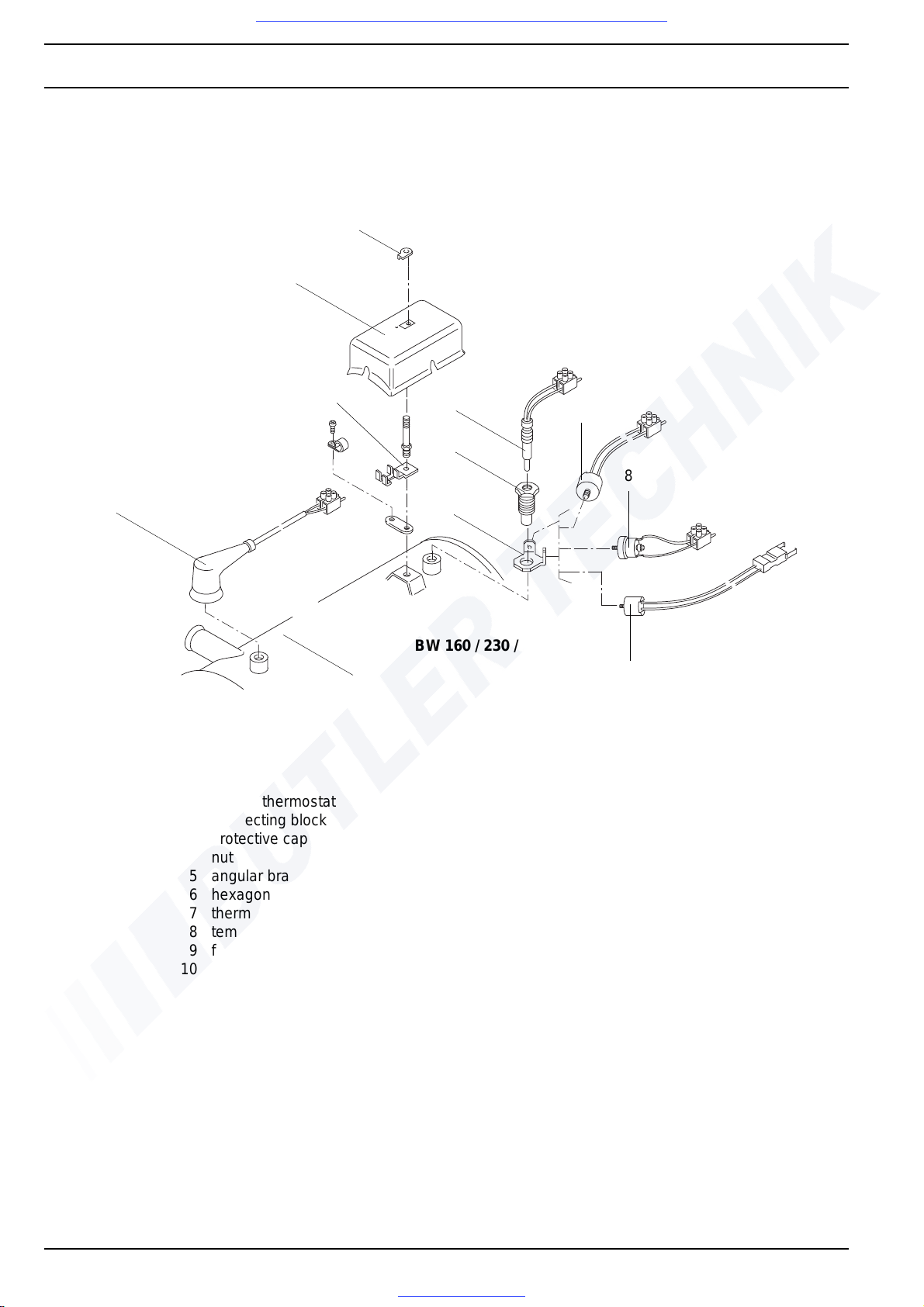
9Repair DBW 160 / 230 (2020) / 300 / 350
Visit www.butlertechnik.com for more technical information and downloads.
www.butlertechnik.com
4
3
2
1
10
1 control thermostat
2 connecting block
3 protective cap
4 nut
5 angular bracket
6 hexagon head plug
7 thermal fuse
8 temperature limiter
9 fan thermostat
10 heat exchanger
7
6
5
DBW 160 / 230 / 300 / 350
1
8
9
Fig. 901 Replacement of temperature limiter, control thermostat, fan thermostat and thermal fuse
908
Page 65
DBW 160 / 230 (2020) / 300 / 350 9Repair
Visit www.butlertechnik.com for more technical information and downloads.
www.butlertechnik.com
9.2.3 Replacing the fan thermostat
9.2.3.1 Removal
1. Remove nut (4, Fig. 901) and ta ke off protective
cap (3).
2. Disconnect electrical conn ection to fan thermostat (9).
3. Unscrew fan th ermostat from an gular bracket ( 5) and
remove.
4. Carry out measures on components in disassembled
state (see 9.1.1).
9.2.3.2 Installation
1. Screw fan thermostat (9, Fig. 901) manually into
angular bracket (5).
2. Establish electrical connection.
3. Attach protective cap (3) and secure with nut (4).
9.2.4 Replacing the thermal fuse
9.2.4.1 Removal
1. Remove nut (4, Fig. 901) and ta ke off protective
cap (3).
2. Disconnect electrical connection to thermal fuse (7) a t
connecting block (2).
3. Unscrew thermal fuse by hand from hexagon head
plug (6) and remove.
4. Carry out measures on components in disassembled
state (see 9.1.1).
9.2.4.2 Installation
1. Screw thermal fu se (7, Fig. 901) by hand into hexagon
head plug (6).
2. Establish electrical connection.
3. Attach protective cap (3) and secure with nut (4).
9.2.6 Replacing the burner head
9.2.6.1 Removal
NOTE
Before disconnecting the connectors or connections
between the wiring harness and the measurement and
control sensors, the pin allocations should be marked or
noted down.
DBW 300.62 without split pin.
1. Disconnect connections to the measurement and
control sensors on the heat exchanger and loosen
wiring harness.
2. If required, dismantle fuel lines.
3. Loosen nuts (2, Fig. 903) until bolts can be swung out.
4. Swing bolts (3) out, pull out split pin (1) and remove.
5. Remove burner head (4).
6. Carry out measur es on componen ts in disassembled
condition (see 9.1.1).
9.2.6.2 Installation
1. Locate burner head (4, Fig. 903), swing bolts(3) in and
tighten nuts (2) by hand.
2. Insert split pin (1) in accordance with the intended
swing direction and secure.
3. Swing bolts (1) in and tighten hand-tight with nut (3) to
prevent stress.
3. Torque nuts (3)
- in DBW 160 to 5.0 Nm + 1 Nm,
- in DBW 230 / 300 / 350 to 8.0 Nm +/- 10%.
4. If required, connect fuel lines.
5. Establish electrical connections.
9.2.5 Replacing the control unit
9.2.5.1 Removal
1. Disconnect connector from control unit (1 or 3, Fig.
902).
2. With control unit 1553, spread retaining clamp (2), if
required, and pull control unit out.
3. Carry out me asures on compo nents in disassemb led
condition (see 9.1.1).
9.2.5.2 Installation
1. Insert control unit 155 3 (1) with retaining clamp (2)
into guide rails at the side of the protective cap (4) and
slide in until it makes contact.
2. Plug connector into control unit.
909
Page 66
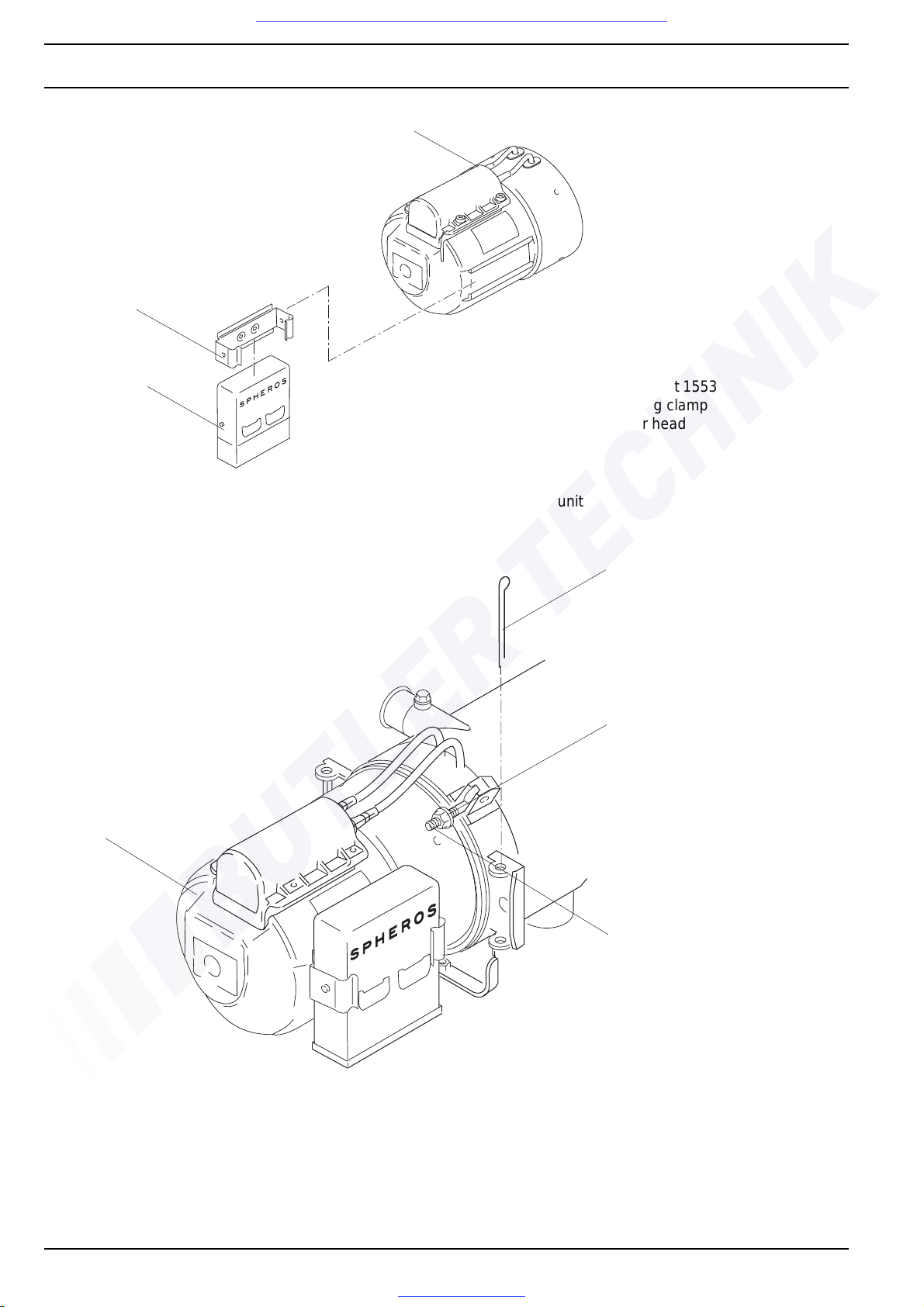
9Repair DBW 160 / 230 (2020) / 300 / 350
Visit www.butlertechnik.com for more technical information and downloads.
www.butlertechnik.com
3
2
1
Fig. 902 Replacement of the control unit
1 control unit 1553
2 retaining clamp
3 burner head
1
(not available with DBW
2
910
4
3
1 split pin
2 nut (2)
3 bolt (2)
4 burner head
NOTE
• Depending on the swing direction of the burner head,
the split pin can be located on the other side.
• The illustration shows the burner head of the DBW 160
series heaters.
Fig. 903 Replacement of the burner head
Page 67
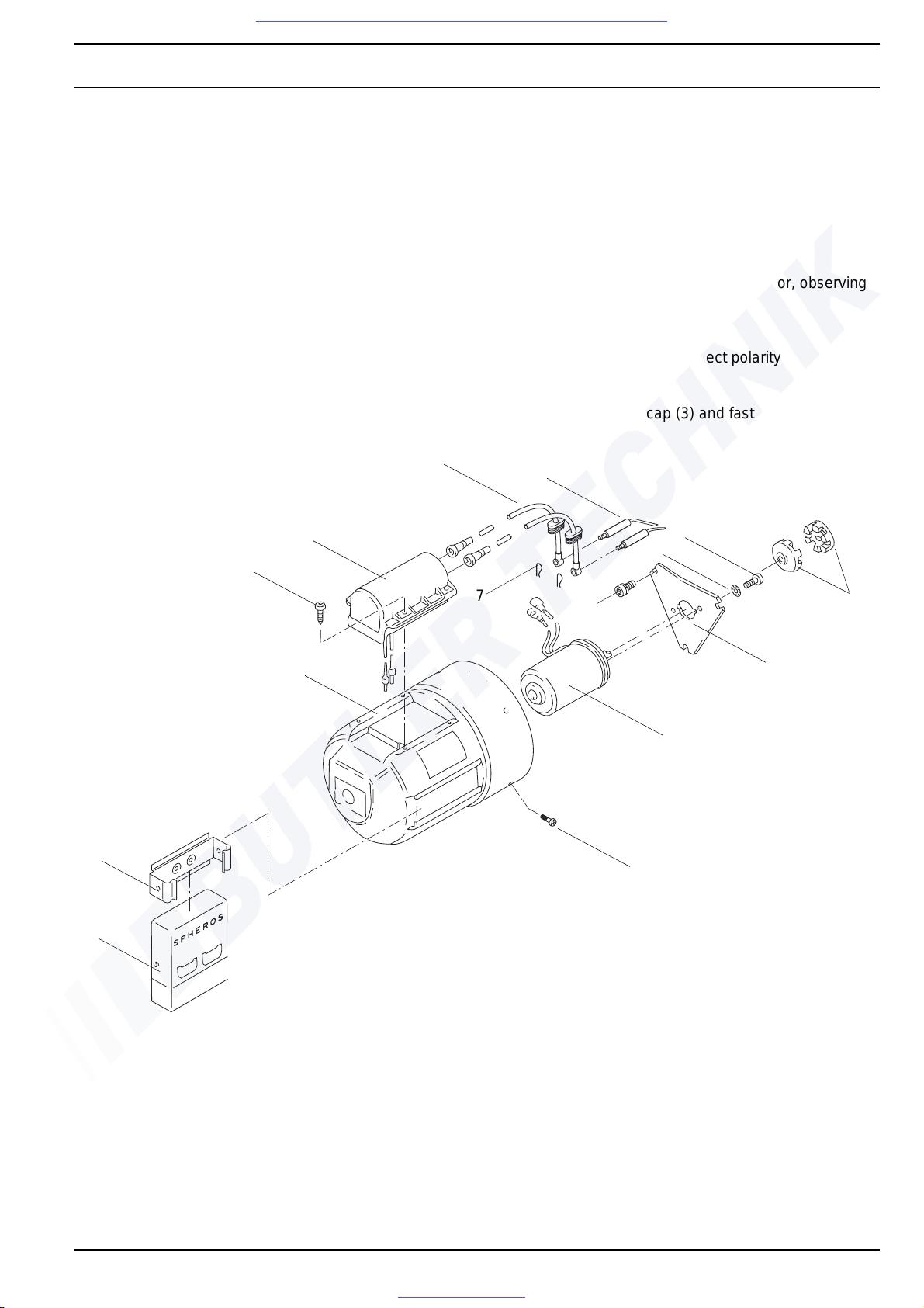
DBW 160 / 230 (2020) / 300 / 350 9Repair
Visit www.butlertechnik.com for more technical information and downloads.
www.butlertechnik.com
9.2.7 Replacing the motor
9.2.7.1 Removal
1. Remove bolts (15, Fig. 904) on protective cap (3) pull
protective cap off to the front.
2. Disconnect electrical connections to motor (14).
3. Unscrew bolts (9) and remove motor (14) with
flange (13).
4. Pull coupling (12) off motor shaft and remove.
5. Remove bolts (11) with se rrated lock washers (10), lift
off motor (14) and remove.
6. Carry out me asures on compo nents in disassemb led
condition (see 9.1.1).
6
5
4
9.2.7.2 Installation
1. Locate motor (14, Fig. 904) and fasten to flange (13)
by means of serrated lock washers (10) and
bolts (11).
2. Torque bolts to 5 Nm + 1 Nm.
3. Fit coupling (12) onto motor shaft.
4. Fasten flange (13) with bolts (9).
5. Torque bolts to 5 Nm + 1 Nm.
6. Establish electrical connections to motor, observing
wiring colour codes.
NOTE
With DBW 300.62, observe correct polarity
( „—“ ^
= brown line)
7. Slide on protective cap (3) and fasten with bolts (15).
8
11
10
7
3
2
1
1 control unit 1553
2 retaining clamp for control unit
1553
3 protective cap
4 bolt (4)
5 electronic ignition unit
6 ignition cable (2)
7 retaining clamp (2)
8 ignition electrodes (2)
9
13
14
15
9bolt (3)
10 serrated lock
washer (2)
11 bolt (2)
12 coupling
13 flange
14 motor
15 bolt (4)
12
Fig. 904 Replacement of the motor
NOTE
The illustration shows the motor of the DBW 160 series heaters.
911
Page 68
9Repair DBW 160 / 230 (2020) / 300 / 350
Visit www.butlertechnik.com for more technical information and downloads.
www.butlertechnik.com
9.2.8 Replacing the high-pressure nozzle
9.2.8.1 Removal
1. Swing burner head open (see 8.5.1).
2. Unscrew high-pressure nozzle (11, Fig. 905) and
remove.
3. Carry out meas ures on componen ts in disassembled
condition (see 9.1.1).
9.2.8.2 Installation
1. Screw in high-pressur e nozzle (11, Fig. 905) and
torque to 20 Nm.
2. Swing burner head closed (see 8.5.1).
9.2.9 Replacing the nozzle-block preheater
9.2.9.1 Removal
1. Swing burner head open (see 8.5.1).
2. Pull off retaining clamp (3, Fig. 905) and remove.
3. Disconnect electrical connection.
4. Pull out heating element (2) from side of nozzle block
(15) and remove.
5. Carry out meas ures on componen ts in disassembled
condition (see 9.1.1).
9.2.9.2 Installation
1. Establish electrical connection.
2. Slide heating element (2, Fig. 905) into nozzle block
(15) and secure with retaining clamp (3).
3. Swing burner head closed (see 8.5.1).
9.2.11 Replacing the flame sensor
9.2.11.1Removal
1. Swing burner head open (see 8.5.1).
2. Disconnect electr ical connection of flame sensor
(10/10a, Fig. 905).
3. Remove bolt (14) and flame sensor (10).
4. Carry out measures on components in disassembled
state (see 9.1.1).
9.2.11.2Installation
1. Locate flame senso r (10, Fig. 905) and fasten with
bolt (14).
2. Torque bolt to 1.3 Nm.
3. Establish electrical connection.
4. Swing burner head closed (see 8.5.1).
9.2.12 Replacing the ignition electrodes
9.2.12.1Removal
1. Swing burner head open (see 8.5.1).
2. Remove bolt (8, Fig. 905).
3. Take off washer (7) and clamp (6) and remove.
4. If required, remove circlip (13) and take off and
remove disk (12).
5. If required, slide back insulation on ignition cable.
6. Pry reta ining clamps (5) off ignition electrodes ( 9) and
remove.
7. Lift off ignition ele ctrodes (9) and remove.
8. Carry out measures on components in disassembled
condition (see 9.1.1).
9.2.10 Replacing the electronic ignition unit
9.2.10.1Removal
1. Swing burner head open (see 8.5.1).
2. Pry connector off electrodes.
5. Unscrew screw (5) fro m electronic ignition unit (6) and
remove electronic ignition unit.
6. Disconnect electrical connections.
7. Carry out meas ures on componen ts in disassembled
condition (see 9.1.1).
9.2.10.2Installation
1. Establish electrical connections.
2. Locate electronic ignition unit (6, Fig. 904) an d fasten
with screws (5).
3. Torque screws to 0.8 Nm.
4. Route ignition cable (4) through grommets into
electronic ignition unit (6).
5. Slide ignition cable onto ignition electrodes (9) and
secure with retaining clamps (8).
6. Swing burner head closed (see 8.5.1).
9.2.12.2Installation
1. Mount disk (12, Fig. 905) and secur e with circlip (13),
if required.
2. Insert ignition electrodes (9) through disk (12), align
them and fasten with clamp (6), washer (7) and
bolt (8).
3. Torque bolt (8) to 1.7 Nm.
4. Slide ignition cable (4) on and secure with retaining
clamps (5).
5. If required, slide insulation on ignition electrodes.
6. Swing burner head closed (see 8.5.1).
912
Page 69
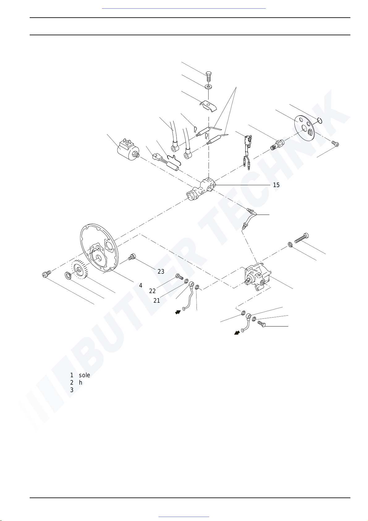
DBW 160 / 230 (2020) / 300 / 350 9Repair
Visit www.butlertechnik.com for more technical information and downloads.
www.butlertechnik.com
8
7
9
6
13
4
1
3
2
5
11
10
12
14
15
25
26
27
1 solenoid valve
2 heating element
3 retaining clamp
4 ignition cable (2)
5 retaining clamp (2)
6 clamp
7 washer
8 bolt
9 ignition electrode (2)
10 flame sensor
24
23
22
21
20
21
11 high-pressure nozzle
12 disk
13 circlip
14 bolt
15 nozzle block
16 pressure line
17 bolt (2)
18 washer (2)
19 fuel pump
20 fuel line (2)
21
16
17
18
19
20
21
22
21 washer (4)
22 banjo bolt (2)
23 bolt (4)
24 nozzle-block plate *
25 spur gear
26 circlip
27 bolt (2)
Fig. 905 Replacement of nozzle block, nozzle-block preheater, hi gh-pressure nozzle and flame sensor.
913
Page 70
9Repair DBW 160 / 230 (2020) / 300 / 350
Visit www.butlertechnik.com for more technical information and downloads.
www.butlertechnik.com
9.2.13 Replacing the fuel pump
9.2.13.1Removal
1. Swing burner head open (see 8.5.1).
2. Remove ignition electrodes (see 9.2.12.1).
3. Remove banjo bo lts ( 22, Fig. 905) an d washe rs (21) ,
take off fuel lines (20) and remove.
4. Loosen bolt-connections on pressure line (16), take
off pressure line and remove.
5. Remove bolts (23) and lift off nozzle-block plate (24).
6. Remove circlip (26) and take off spur gear (25) and
remove.
7. Remove bolts (17) and washers (18), take off fuel
pump (19) and remove.
8. Carry out measures on components in disassembled
condition (see 9.1.1).
9.2.13.2Installation
1. Locate fuel pump (19, Fig. 905) and fasten with bolts
(17) and washers (18).
2. Torque bolts to 3.0 Nm.
3. Mount spur gear (25) and secure with circlip (26).
4. Insert nozzle-block plate (24) and fasten with
bolts (23).
5. Torque bolts to 5.5 Nm.
6. Locate pressure line (1 6) and torque bolt-connections
to 6 ± 0.6 Nm.
7. Locate fuel lines (2 0) and faste n with banjo bolts ( 22)
and washers (21).
8. Torque banjo bolts to 15 ± 1.5 Nm.
9. Install ignition electrode s (see 9.2.12.2).
10. Swing burner head closed (see 8.5.1).
9.2.14 Replacing the solenoid valve
9.2.14.1Removal
1. Swing burner head open (see 8.5.1).
2. Remove ignition electrodes (see 9.2.12.1).
3. Remove nozzle-block preheater (see 9.2.9.1).
4. Remove bolts (23, Fig. 905) and lift off nozzle-block
plate (24).
5. Disconnect electrical connections on solenoid valve.
6. Remove nut (1, Fig. 90 7), take off solenoid-valve head
(3) and washer (2) and remove.
7. If required, unscrew solenoid-valve body (4), remove
sealing ring (5), pin (6), spring (7) and stud (8).
8. Carry out measures on components in disassembled
condition (see 9.1.1).
9.2.14.2Installation
1. Place sealing ring (5, Fig. 907) on solenoid-valve
body (4).
2. Insert spring (7) and pin (6) into stud (8).
3. Insert stud with spring and pin into solenoid-valve
body (4).
4. Screw solenoid-valve body (4) into nozzle block (9).
5. Torque bolt to 11.5 Nm.
6. Place solenoid-valve head (3) on solenoid-valve bod y
and fasten with washer (2) and nut (1).
7. Torque nut to 2 Nm.
8. Fasten nozzle-block plate ( 24, Fig. 905) with
bolts (23).
9. Torque bolts to 5.5 Nm.
10. Install nozzle-block preheater (see 9.2.9.2).
11. Install ignition electrodes (see 9.2.12.2).
12. Establish electrical connections to solenoid valve.
13. Swing burner head closed (see 8.5.1).
9.2.15 Replacing the combustion chamber
9.2.15.1Removal
1. Swing burner head open (see 8.5.1).
2. Pull combustion chamber (1, Fig. 908 ) out of the heat
exchanger (2) and remove.
3. Carry out measures on components in disasse mbled
condition (see 9.1.1).
9.2.15.2Installation
1. Slide combustion chamber (1, Fig. 908) into heat
exchanger (2) until it makes contact.
2. Swing burner head closed (see 8.5.1).
9.2.16 Thermostat of the nozzle-block preheater
9.2.16.1Removal
1. Swing burner open (see 8.5.1).
2. Disconnect electrical connection.
3. Unscrew thermostat (4, Fig. 906) from nozzle-block
plate (7) or unscrew disk (1) and remove with bolt (5),
tab (6) or nut (3) and serrated lock washer (2).
4. Carry out measures on components in disassembled
state (see 9.1.1).
9.2.16.2Installation
1. Locate therm ostat (4, Fig. 906) and fasten with tab (6)
and bolt (5) to nozzle-block plate (7) or with nut (3) and
serrated lock washer (2) to disk (1).
2. Establish electrical connection.
3. Swing burner closed (see 8.5.1).
914
Page 71
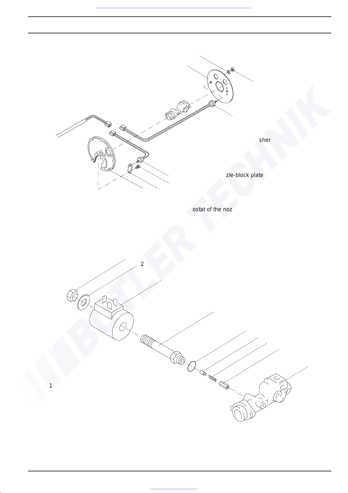
DBW 160 / 230 (2020) / 300 / 350 9Repair
Visit www.butlertechnik.com for more technical information and downloads.
www.butlertechnik.com
2
1
3
DBW 230 / 300 / 350
4
1 disk
2 serrated lock washer
3 nut
4 thermostat
5 bolt
DBW 160
4
5
67
6 tab
7 nozzle-block plate
Fig. 906 Replacement of the thermostat of the nozzle-block preheater
1
2
3
4
5
6
7
8
9
1 nut
2 washer
3 solenoid valve head
4 solenoid valve body
5 sealing ring
6pin
7spring
8 stud
9 nozzle block
Fig. 907 Replacement of the solenoid valve
915
Page 72
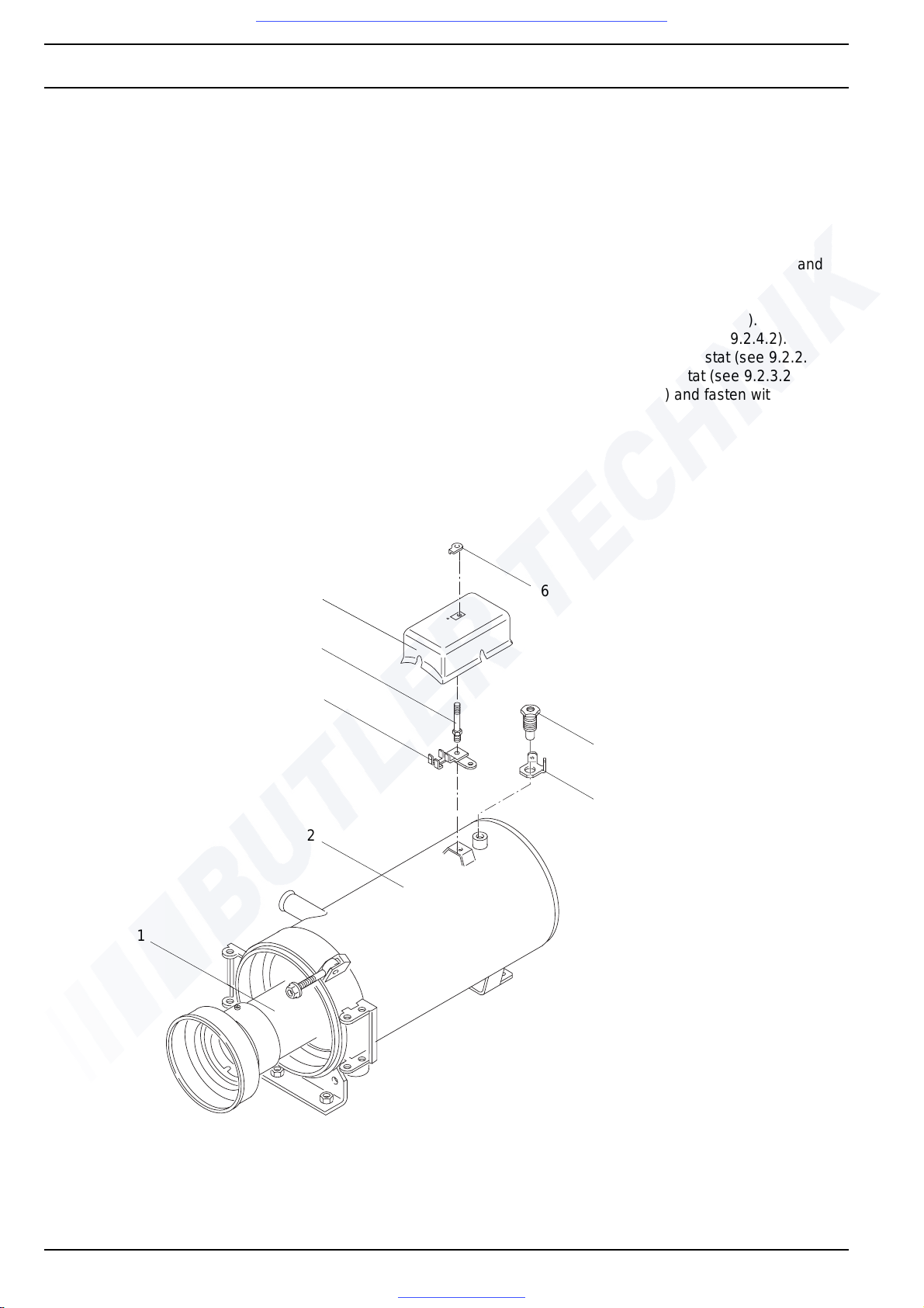
9Repair DBW 160 / 230 (2020) / 300 / 350
Visit www.butlertechnik.com for more technical information and downloads.
www.butlertechnik.com
9.2.17 Replacing the heat exchanger
9.2.19.1 Removal
1. If required, remove nut (6, Fig. 908) on cover (5), lift
off cover and remove.
2. Remove temperature limiter (see 9.2.1.1).
3. If required, remove thermal fuse (see 9.2.4.1).
4. If required, remove control thermostat (see 9.2.2.1 ).
5. If required, remove fan thermostat (see 9.2.3.1).
6. Remove bolt (4), lift off bracket (3) with electrical
connections and remove.
7. Remove hexagon head plug (7) and lift off together
with angular bracket (8) and remove.
8. Remove burner head (see 9.2.6.1).
9. Pull combustion chamber (1) out of the heat
exchanger (2) and remove.
10. Remove heat exchanger (2).
11. Carry out measures on components in disassembled
condition (see 9.1.1).
9.2.19.2 Installation
1. Slide combustion chamber (1, Fig. 908) into heat
exchanger (2) until it makes contact.
2. Attach burner head (see 9.2.6.2).
3. Locate angular bracket (8) and screw in hexagon
head plug (7).
4. Tighten hexagon head plug hand-tight.
5. Locate bracket (3) with electrical connections and
fasten with bolt (4).
6. Tighten bolt hand-tight.
7. Install temperature limiter (see 9.2.1.2 ).
8. If required, install thermal fuse (see 9.2.4.2).
9. If required, install control thermostat (see 9.2.2.2).
10. If required, install fan thermostat (see 9.2.3.2).
11. If required, attach cover (5) and fasten with nut (6).
5
6
4
3
7
8
2
1
1 combustion
chamber
2 heat exchanger
3 bracket *
4 bolt
5 cover
6 nut
7 hexagon head plug
8 angular bracket
Fig. 908 Replacement of the combustion chamber and the heat exchanger
916
* not available with DBW 300.62.
Page 73
DBW 160 / 230 (2020) / 300 / 350 9Repair
Visit www.butlertechnik.com for more technical information and downloads.
www.butlertechnik.com
9.2.18 Replacing the nozzle block
9.2.18.1Removal
1. Swing burner head open (see 8.5.1).
2. Remove ignition electrodes (see 9.2.12.1).
3. Remove high-pressure nozzle (see 9.2.8.1).
4. If required, Remove nozzle-block preheater
(see 9.2.9.1).
5. Remove solenoid valve (see 9.2.14.1).
6. Loosen bolt-c onnections on pressure line (16, Fig.
905) and take off pressure line and remove.
7. Remove bolts (23) and lift off nozzle-block plate (24).
8. Remove bolts (27), lift off nozzle block (15) and
remove.
9. Carry out measures on components in disassembled
condition (see 9.1.1).
9.2.18.2Installation
1. Locate nozzle block (15, Fig. 905) and fasten with
bolts (27).
2. Torque bolts to 5.5 Nm.
3. Locate nozzle-block plate (24) and fasten with
bolts (23).
4. Torque bolts to 5.5 Nm.
5. Locate pressure line (16) and torque bolt-connections
to 6 ± 0.6 Nm.
6. Install solenoid valve (see 9.2.14.2).
7. If required, Install nozzle-block preheater (see
9.2.9.2).
8. Install high-pressure nozzle (see 9.2.8.2).
9. Install ignition electrodes (see 9.2.12.2).
10. Swing burner head closed (see 8.5.1).
9.2.19 Replacing the combustion air fan
9.2.19.1Removal
1. Remove burner head (see 9.2.6.1).
2. Remove motor (see 9.2.7.1).
3. Remove bolts (6, Fig. 909 from the nozzle-block
plate (5).
4. Remove bolts (1) and washers (2).
5. Pull engine mount (3) off the shaft.
6. Remove combustion air fan (4).
7. Carry out measur es on componen ts in disassembled
state (see 9.1.1).
9.2.19.2Installation
1. Only DBW 160:
check gap dimension on impeller (see 9.1.1.4)
2. Locate combustion air fa n (4, Fig. 909) and fasten with
bolts (6) to the nozzle-block plate (5).
3. Torque bolts (6) to 5.5 Nm.
4. Fit engine mount (3) onto shaft and fasten with bolts
(1) and washers (2).
5. Torque nuts (1)
- in DBW 160 to 5.5 Nm + 1 Nm,
- in DBW 230 / 300 / 350 to 8.0 Nm +/- 10%.
6. Install engine (see 9.2.7.2).
7. Install burner head (see 9.2.6.2).
917
Page 74
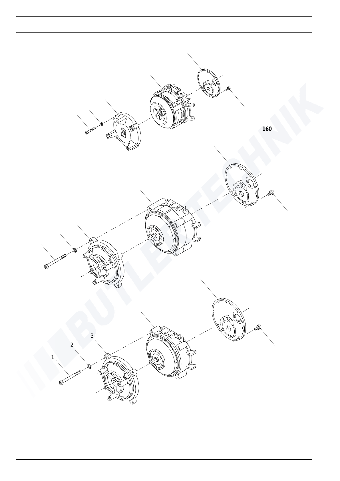
9Repair DBW 160 / 230 (2020) / 300 / 350
Visit www.butlertechnik.com for more technical information and downloads.
www.butlertechnik.com
5
4
3
2
1
5
4
6
DBW 160
3
2
1
3
2
1
4
DBW 350
5
4
DBW 230 / DBW 300
6
6
1 bolt (3)
2washer (3)
3 engine mount
Fig. 909 Replacement of the combustion air fan
918
4 Combustion air fan
5 nozzle-block plate
6 bolt (4)
Page 75
DBW 160 / 230 (2020) / 300 / 350 9Repair
Visit www.butlertechnik.com for more technical information and downloads.
www.butlertechnik.com
Notes
919
Page 76
9Repair DBW 160 / 230 (2020) / 300 / 350
Visit www.butlertechnik.com for more technical information and downloads.
www.butlertechnik.com
920
Page 77
DBW 160 / 230 (2020) / 300 / 350 10 Packaging, Storage and Shipping
Visit www.butlertechnik.com for more technical information and downloads.
www.butlertechnik.com
10 Packaging, Storage
and Shipping
10.1 General
Heaters or components to be sent to Spheros GmbH for
testing or repair must be cleaned and packaged in such a
way that they will not be damaged during handling, transport and storage.
CAUTION
Heaters sent in as complete units must be fully drained.
Units and components must be packaged and shipped in
such a way that leakage of fuel and coolant is re liably prevented.
Coolant supply and return flanges and fuel lines must be
sealed with blanking plugs.
During storage, the ambient temperatures stated in
section 4 must not be exceeded.
1001
Page 78
10 Packaging, Storage and Shipping DBW 160 / 230 (2020) / 300 / 350
Visit www.butlertechnik.com for more technical information and downloads.
www.butlertechnik.com
Notes
1002
Page 79
DBW 160 / 230 (2020) / 300 / 350 A Appendix
Visit www.butlertechnik.com for more technical information and downloads.
www.butlertechnik.com
Appendix A
Regular maintenance
A-1
Page 80
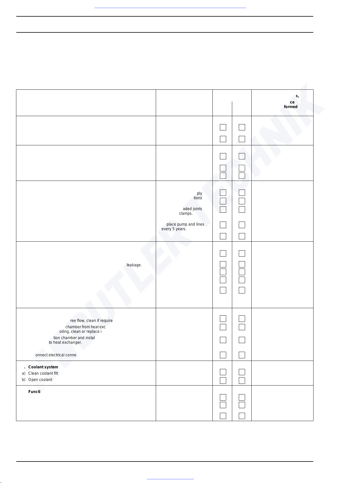
AAppendix DBW 160 / 230 (2020) / 300 / 350
Visit www.butlertechnik.com for more technical information and downloads.
www.butlertechnik.com
Regular maintenance of heater
The maintenance intervals stated below apply to busses
The heater should be checked at regular intervals, but no
later than at the beginning of the heating period when the
heater is used again regularly due to declining ambient
temperatures.
Check / maintenance work Important notes Result Measured values,
and coaches subject to normal operating conditions and
requirements. Intervals may be shortened or extended for
heaters used in other vehicles or applications.
In such cases please contact your Spheros partner.
OK not
OK
Maintenance
work performed
1. Electrical connections
a) Disconnect electrical connections to wiring harness, check for oxida-
tion, spray and reconnect after performing point 5.
b) Check fuses for oxidation and excessive contact resistance.
2. Heat exchanger
a) Check for dark discolouration of paint (local over-
heating).
b) Check for leakage.
c) Clean outside and inside of heater.
3. Fuel system
a) Check fuel lines and connections for leakage.
b) Replace fuel-filter element with seal.
c) Open fuel shut-off valves, if present.
d) Fuel pump and fuel lines.
e) Replace fuel strainer with seals in pump.
4. Burner head
a) Check combustion air intake opening for free flow.
Swing burner head open:
b) Check housing interior for fuel accumulation caused by leakage.
c) Clean sight glass of flame sensor.
d) Check condition of igniter electrodes.
e) Replace atomiser nozzle.
Use suitable contact spray,
e.g. special contact spray
(order no. 101322).
Identify cause of any
overheating (e.g. coolant
circuit); check temperature limiter.
Ensure that fuel supply
and return connections
do not leak!
Tighten threaded joints
and hose clamps.
Replace pump and lines
every 5 years.
Replace bent electrodes.
In case of carbon deposit
Reduce change interval
of fuel filter.
5. Exhaust system
a) Check exhaust line for free flow, clean if required.
b) Remove combustion chamber from heat exchanger, check both parts
for damage and soiling, clean or replace if required.
c) Insert combustion chamber and install burner head. Ensure secure
connection to heat exchanger.
d) Reconnect electrical connections.
6. Coolant system
a) Clean coolant filter element, if present.
b) Open coolant shut-off valves, if present.
7. Function check
a) Open shut-off valve in return line, if present.
b) Check function of heater.
c) Check for smoke during run-on period; change nozzle, if required.
A-2
after a min. heating
period of 10 min.
 Loading...