

Page 1

Klimaanlage
Air Conditioning System
Betriebsanleitung
Operating Instruction
CC 145
05/2010
Ident Nr. 11114709A
Page 2

CC 145
I
Inhaltsverzeichnis / Table of contents
Inhalt . . . . . . . . . . . . . . . . . . . . . . . . . . . . . . . . . . . . . . . Seite Content. . . . . . . . . . . . . . . . . . . . . . . . . . . . . . . . . . . . . . . Page
1 Geräteübersicht . . . . . . . . . . . . . . . . . . . . . . . . . . . . . . . .1
1.1 Klimaanlage CC 145 . . . . . . . . . . . . . . . . . . . . . . . . . . .1
2 Bedienelemente und Anzeige . . . . . . . . . . . . . . . . . . . . .2
2.1 Bedienteil . . . . . . . . . . . . . . . . . . . . . . . . . . . . . . . . . . .2
2.2 Funktion der Bedienelemente und Anzeiger . . . . . . . . .3
3 Betrieb . . . . . . . . . . . . . . . . . . . . . . . . . . . . . . . . . . . . . . .4
3.1 Bedienung - Normalbetrieb . . . . . . . . . . . . . . . . . . . . . .4
3.1.1. Anzeigefeld . . . . . . . . . . . . . . . . . . . . . . . . . . . . . . . . . . . . 4
3.1.2 Solltemperatur . . . . . . . . . . . . . . . . . . . . . . . . . . . . . . . . . . 4
3.1.3 Lüftungsfunktion . . . . . . . . . . . . . . . . . . . . . . . . . . . . . . . . 4
3.1.4 Kühlbetrieb . . . . . . . . . . . . . . . . . . . . . . . . . . . . . . . . . . . . 4
3.2 Bedienung - Betrieb bei Fehlern . . . . . . . . . . . . . . . . . .4
3.2.1 Betrieb bei Fehlern - Bedienteil funktionsfähig . . . . . . . . . 4
3.3 Störungen an der Elektrik . . . . . . . . . . . . . . . . . . . . . . .5
3.4 Störungen an der Klimaanlage . . . . . . . . . . . . . . . . . . .5
3.5 Störungen im Kühlkreis . . . . . . . . . . . . . . . . . . . . . . . . .5
4 Wartung . . . . . . . . . . . . . . . . . . . . . . . . . . . . . . . . . . . . . .6
4.1 Allgemeines . . . . . . . . . . . . . . . . . . . . . . . . . . . . . . . . .6
4.2 Vorbeugende Wartung . . . . . . . . . . . . . . . . . . . . . . . . .7
5 Technische Daten . . . . . . . . . . . . . . . . . . . . . . . . . . . . . .9
6 Fehlersuche und -beseitigung . . . . . . . . . . . . . . . . . . . .10
7 Schaltpläne . . . . . . . . . . . . . . . . . . . . . . . . . . . . . . . . . .12
7.1 Allgemeines . . . . . . . . . . . . . . . . . . . . . . . . . . . . . . . . .12
1 Equipment General Arrangement . . . . . . . . . . . . . . . . 13
1.1 Air conditioner CC 145 . . . . . . . . . . . . . . . . . . . . . . . . 13
2 Controls and Indicators . . . . . . . . . . . . . . . . . . . . . . . . . 14
2.1 Control Panel . . . . . . . . . . . . . . . . . . . . . . . . . . . . . . . 14
2.2 Function of Controls and Indicators . . . . . . . . . . . . . . 15
3 Equipment Operation . . . . . . . . . . . . . . . . . . . . . . . . . . 16
3.1 Command Description - Normal Operation . . . . . . . . 16
3.1.1 Display . . . . . . . . . . . . . . . . . . . . . . . . . . . . . . . . . . . . . . .16
3.1.2 Set-point . . . . . . . . . . . . . . . . . . . . . . . . . . . . . . . . . . . . . .16
3.1.3 Ventilation mode . . . . . . . . . . . . . . . . . . . . . . . . . . . . . . .16
3.1.4 Cooling mode . . . . . . . . . . . . . . . . . . . . . . . . . . . . . . . . . .16
3.2 Command Description - Failure Operation . . . . . . . . 16
3.2.1 Failure Operation - Control Panel Functions available . .16
3.3 Electrical Malfunctions . . . . . . . . . . . . . . . . . . . . . . . . 17
3.4 Malfunctions in the Air Conditioning System . . . . . . . 17
3.5 Malfunctions in the Refrigeration Circuit . . . . . . . . . . 17
4. Maintenance Activities . . . . . . . . . . . . . . . . . . . . . . . . . 18
4.1 General . . . . . . . . . . . . . . . . . . . . . . . . . . . . . . . . . . . 18
4.2 Preventive Maintenance . . . . . . . . . . . . . . . . . . . . . . 19
5 Technical Specification . . . . . . . . . . . . . . . . . . . . . . . . 21
6 Failure Diagnosis Table . . . . . . . . . . . . . . . . . . . . . . . . 22
7 Wiring Diagrams . . . . . . . . . . . . . . . . . . . . . . . . . . . . . 24
7.1 General . . . . . . . . . . . . . . . . . . . . . . . . . . . . . . . . . . . 24
Page 3

CC 145
1
1 Geräteübersicht
1.1 Klimaanlage CC 145
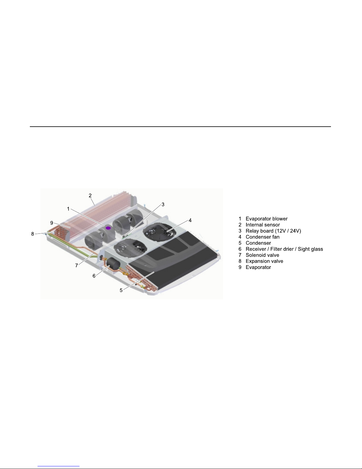
Die Klimaanlage CC 145 und ihre Hauptbauteile sind in Abb. 1 dargestellt.
Abb. 1 CC 145
Page 4
CC 145
2
2 Bedienelemente und Anzeigen
2.1 Bedienteil
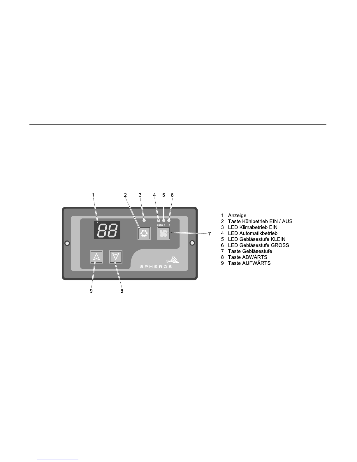
Auf dem Bedienteil der Klimaanlage befinden sich alle Bedienelemente und
Anzeigen für Systemeinstellungen, Betriebsartenwahl und Betriebsanzeigen.
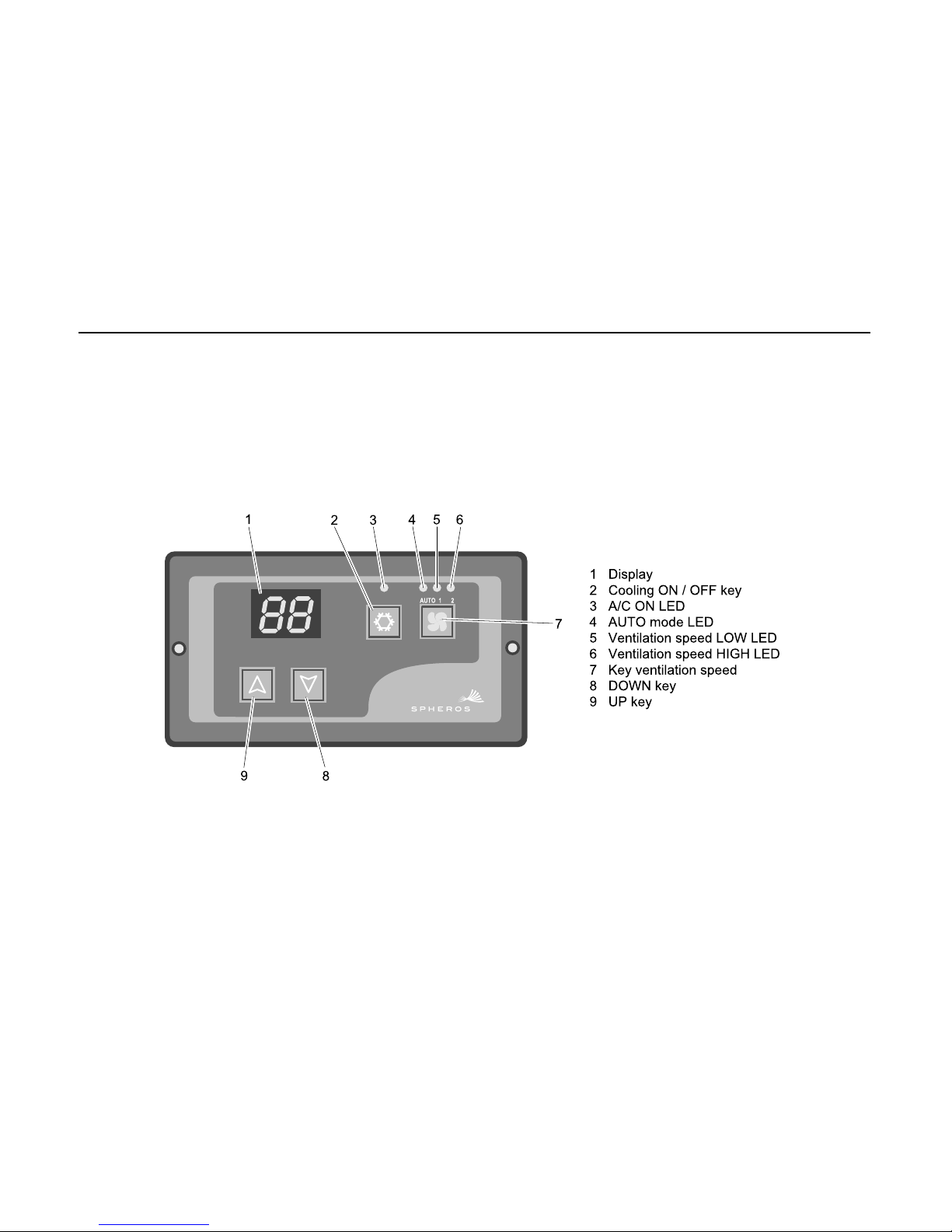
Die Abb. 2 zeigt das Bedienteil mit seinen Bedienelementen und Anzeigen.
Abb. 2 Bedienteil
Page 5
CC 145
3
2.2 Funktion der Bedienelemente und Anzeiger
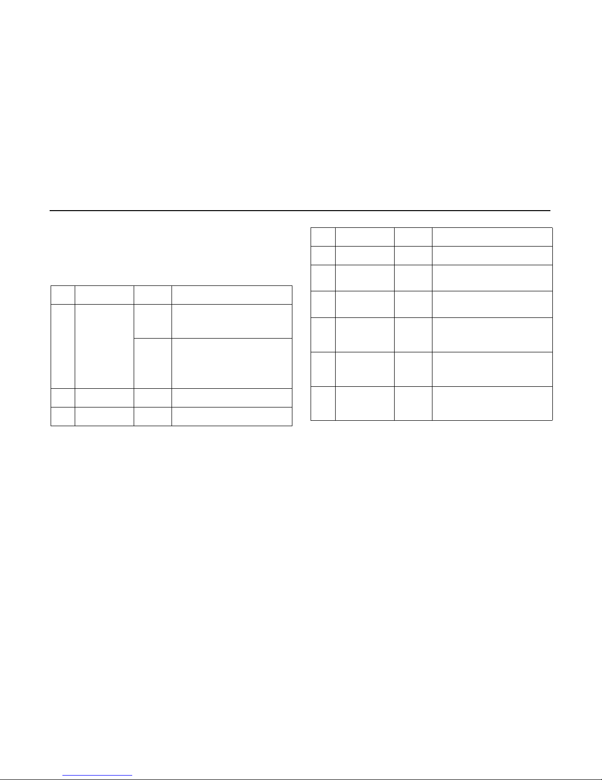
Die Funktion der Bedienelemente und Anzeiger ist in Abb. 3 erklärt.
Anmerkung:
Alle Taster besitzen eine rote LED-Hintergrundbeleuchtung.
Ortszahl,
Abb. 2
Bedienelemente /
Anzeiger
Einstellungen /
Anzeige
Funktion
1 Anzeigefeld oF Zündung ist eingeschaltet, Klimaanlage in
Bereitschaft zum Einschalten durch
Drücken der Taste AUTO. Nur
Gebläsebetrieb möglich durch Drücken
der Taste Gebläse.
Zahl oder
Code
Anlage in Betrieb. Anzeige von
Temperaturen, Gebläsestufen,
Fehlercode und Statusinformationen
abhängig von Betriebsart und
Anzeigewahl. Einzelheiten siehe „Betrieb Bedienung“.
2 Taste Kühlbetrieb
EIN / AUS
gedrückt Schaltet den Kühlbetrieb der Anlage ein.
Erneutes Drücken schaltet den
Kühlbetrieb wieder aus.
3 LED
Klimabetrieb EIN
leuchtet Anzeige Kühlbetrieb EIN
Abb. 3 Funktion der Bedienelemente und Anzeiger
4 LED Betriebsart
AUTO
leuchtet Betriebsart AUTO ist eingeschaltet,
Anlage arbeitet mit Klimaautomatik.
5 LED Gebläsestufe
KLEIN
leuchtet Anzeige der mit der Taste Gebläse
manuell gewählten Gebläsestufe KLEIN.
LED Betriebsart AUTO ist aus.
6 LED Gebläsestufe
GROSS
leuchtet Anzeige der mit der Taste Gebläse
manuell gewählten Gebläsestufe GROSS.
LED Betriebsart AUTO ist aus.
7 Taste Gebläse gedrückt Manuelle Wahl der Gebläsestufe KLEIN
oder GROSS mit den Tasten Aufwärts
bzw. Abwärts zur Übersteuerung der von
der Betriebsart AUTO gewählten
Gebläsestufe, die zuerst angezeigt wird.
8 Taste Abwärts gedrückt Abwärts-Steuertaste bei Systemeinstel-
lungen und Anzeigen in den verschiedenen Betriebsarten einschliesslich
Anlagen-, Prüf- und Statusmeldungen.
9 Taste Aufwärts gedrückt Aufwärts-Steuertaste bei Systemeinstel-
lungen und Anzeigen in den verschiedenen Betriebsarten einschliesslich
Anlagen-, Prüf- und Statusmeldungen.
Ortszahl,
Abb. 2
Bedienelemente /
Anzeiger
Einstellungen /
Anzeige
Funktion
Abb. 3 Funktion der Bedienelemente und Anzeiger
Page 6
CC 145
4
3 Betrieb
3.1 Bedienung - Normalbetrieb
3.1.1 Anzeigefeld
Das numerische Anzeigefeld informiert den Bediener über die gewählte
Solltemperatur.
3.1.2 Solltemperatur
Die Solltemperatur ist die im Innenraum gewünschte Temperatur. Um sie zu
ändern, muss eine der Tasten bzw. gedrückt werten. Die momentan
eingestellte Solltemperatur wird blinkend angezeigt und kann durch Drücken
der Taste bzw. geändert werden.
3.1.3 Lüftungsfunktion
Die Anlage kann im Lüftungsbetrieb eingesetzt werden.
Drücken der Taste aktiviert die Lüftung in kleiner Gebläsestufe, LED (5)
leuchtet.
Ein weiterer Druck auf die Taste aktiviert die Lüftung in großer
Gebläsestufe, LED (5) erlischt, LED (6) leuchtet.
Ein weiterer Druck auf Taste schaltet die Lüftung aus, LED (6) erlischt.
3.1.4 Kühlbetrieb
Der Kühlbetrieb wird durch Taste aufgerufen und startet die Anlage im
Automatikmodus. Dabei wählt die Steuerung automatisch die benötigte
Verdampfergebläsestufe.
Durch Drücken der Taste kann die kleine (1 x drücken) oder große
Gebläsestufe (2 x drücken) manuell eingestellt werden. Eine dritte
Betätigung der Taste ruft wieder den Automatikbetrieb auf.
Die LED (3) leuchtet, solange die Kompressorkupplung geschlossen ist. Bei
geöffneter Kompressorkupplung blinkt die LED (3).
Um extrem kurze Schaltzyklen der Kompressorkupplung zu vermeiden, ist
ein Mindestintervall von 30 Sekunden zwischen Aus- und Einschalten
programmiert.
3.2 Bedienung - Betrieb bei Fehlern
3.2.1 Betrieb bei Fehlern - Bedienteil funktionsfähig
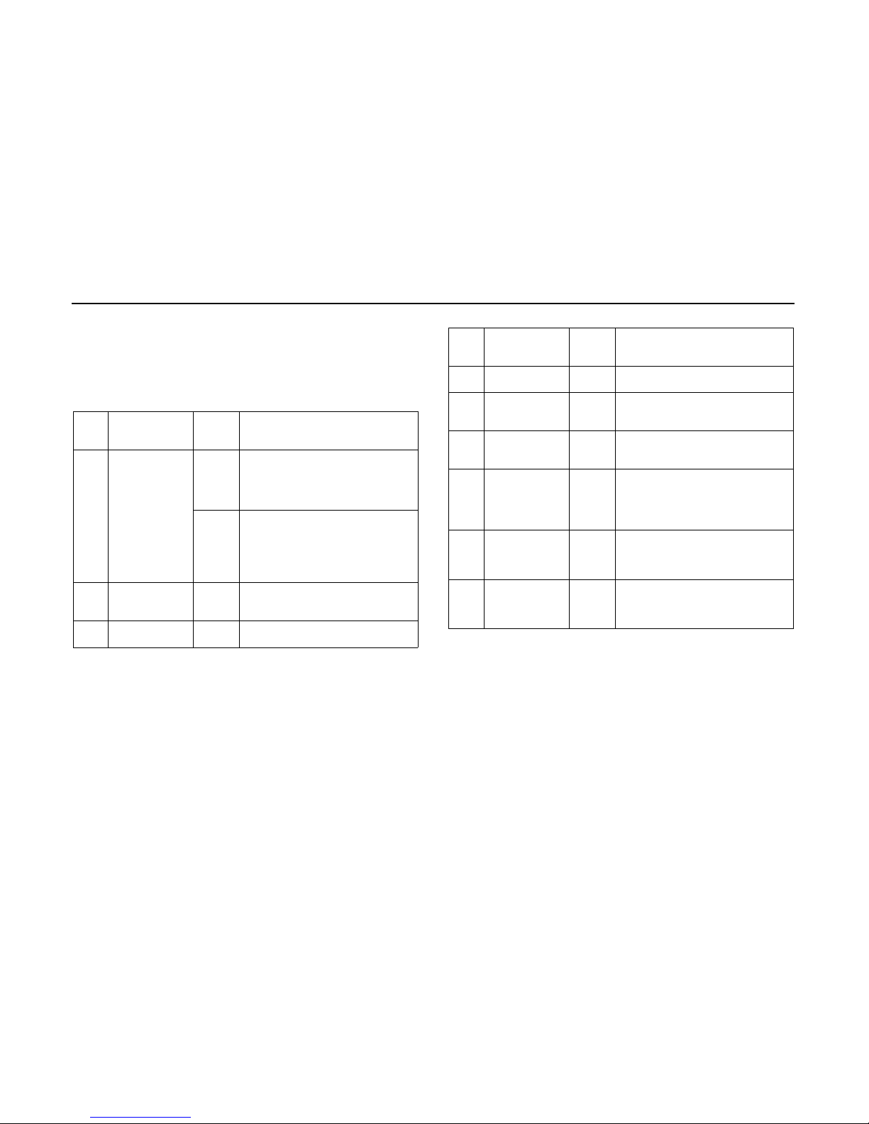
Das Bedienteil gibt im Bedarfsfall folgende Fehlermeldungen am
numerischen Display aus.
Die folgende Abbildung in Tabellenform listet alle möglichen Fehleranzeigen
und deren Bedeutung auf.
.
Fehler
anzeige
Beschreibung Aktion
Fehler
Druckschalter /
Vereisungsthermostat
Druckschalter prüfen,
Vereisungsthermostat am Verdampfer
prüfen,
Kältemitteldrücke prüfen,
Verdampfergebläse prüfen
Temperaturfühler
Unterbrechung
Temperaturfühler/Kabelbaum prüfen
Temperaturfühler
Kurzschluss
Temperaturfühler/Kabelbaum prüfen
Fehler
Stromversorgung
Bordspannung messen,
Verkabelung prüfen,
Generator prüfen
Abb. 4 Fehlercodeanzeige
Page 7

CC 145
5
3.3 Störungen an der Elektrik
Die einzelnen Schaltkreise müssen gemäß Schaltplan systematisch geprüft
werden. Vor allem sollten Steckverbindungen und elektrische Bauteile wie
Schalter, Relais, usw. auf Durchgang geprüft werden.
Die folgenden, möglichen Ursachen von Störungen sollten von vornherein
durch Prüfung ausgeschlossen werden:
- korrodierte Steckerkontakte
- lockere Steckerkontakte
- korrodierte Leitungen
- korrodierte Batteriepole
- ausgefranste Kabel
- schadhafte Sicherungen
3.4 Störungen an der Klimaanlage
Folgende Störungen können an der Klimaanlage auftreten und damit zu
einem Ausfall der Anlage führen:
- Vereisungsschutz fehlerhaft
- Hochdruck-/Niederdruckschalter fehlerhaft
- schadhafter Verdichter
- Verflüssiger oder Verflüssigergebläse schadhaft
- Kältemittelverlust durch Undichtigkeit
- Luftfilter oder Wärmetauscherlamellen verschmutzt
- Kühlkreis blockiert (z. B. Filtertrockner)
- Expansionsventil defekt
3.5 Störungen im Kühlkreis
Treten Störungen im Kühlkreis der Klimaanlage auf, muss die Anlage geprüft
und fachgerecht durch eine autorisierte Fachwerkstatt instandgesetzt
werden.
ACHTUNG
Das Kältemittel darf unter keinen Umständen in die Umwelt gelangen
(8, CFC-Halon Umweltschutzverordnung v. 06.05.1991).
Kältemittelmenge in der Anlage überprüfen.
- nach ca. 5 Minuten Betrieb der Klimaanlage und geschlossener
Kompressorkupplung bei erhöhter Motordrehzahl darf der Kältemittelfluss
im Schauglas keine Blasen zeigen.
Während der kalten Jahreszeit:
- damit die Wellendichtung des Kälteverdichters nicht austrocknet, die
Klimaanlage einmal im Monat bei einer Umgebungstemperatur von
min. > 8 °C ungefähr 15 Minuten lang laufen lassen.
Der Kältemittelsammler und alle Bauteile der Klimaanlage sollten im Rahmen
von Wartungsarbeiten einer Sichtprüfung unterzogen werden. Es ist
besonders auf Anzeichen von Korrosion und mechanischen Schäden zu
achten.
Alle Teile in nicht einwandfreiem Zustand müssen aus Sicherheitsgründen
ausgetauscht werden
ACHTUNG:
Gemäß der Verordnung über Druckbehälter muss der Betreiber den
Kältemittelsammler in regelmäßigen Zeitabständen von einem Fachmann
überprüfen lassen.
Anmerkung:
Um einen störungsfreien Betrieb der Klimaanlage zu gewährleisten, muss
das Kältemittel und der Filtertrockner 6 Monate nach Inbetriebnahme des
Fahrzeugs erneuert werden.
Der Filtertrockner sollte jährlich bei Beginn des Fahrzeugeinsatzes
gewechselt werden. Dies sollte von einer autorisierten Werkstatt
durchgeführt werden, die außerdem eine Funktionsprüfung sowie eine
Leckprüfung der Klimaanlage vornimmt.
Garantieansprüche können nur geltend gemacht werden, wenn der Betreiber
die Einhaltung der Sicherheits- und Wartungsvorschriften nachweisen kann.
Page 8

CC 145
6
4 Wartung
4.1 Allgemeines
Eine Klimaanlage ist - so wie alle anderen Bauteile eines Fahrzeugs - ständig
mechanischen Kräften und Beanspruchung ausgesetzt. Um einen
störungsfreien Betrieb der Anlage zu gewährleisten und Schäden an den
Teilen zu vermeiden, ist es wichtig, dass alle vorgeschriebenen
Wartungsmaßnahmen durch ausgebildetes Fachpersonal für Klimatechnik
durchgeführt werden.
Der richtige Umgang mit der Anlage, einschließlich
Wartungsnachweisführung (Wartungsplan mit entsprechenden Einträgen) ist
eine Voraussetzung für die Anerkennung von Garantieansprüchen bei
Schäden an Bauteilen, die regelmäßig gewartet werden müssen.
Unabhängig von den vorgeschriebenen Wartungsintervallen gemäß
Wartungsplan müssen alle Befestigungen des Klimageräts und die
Kältemittelanschlüsse während der ersten vier Wochen nach Inbetriebnahme
des Fahrzeugs bzw. der Klimaanlage auf festen Sitz geprüft werden.
Auch wenn die Klimaanlage nicht in Betrieb ist, kann an Bauteilen Verschleiß
durch normale Alterung oder Beanspruchungen durch den Betrieb des
Fahrzeugs auftreten. Alle im Wartungsplan vorgegebenen Prüfungen
müssen deshalb unabhängig von Betriebsstunden der Klimaanlage
durchgeführt werden.
Ein Kältemittelverlust ist auch bei dichten Kältemittelanschlüssen möglich.
Aufgrund der Materialstruktur der Kältemittelleitungen kann es abhängig von
der Umgebungstemperatur zu verschieden starkem Kältemittelschwund
kommen. Bei relativ hohem Kältemittelverlust innerhalb kurzer Zeitabstände
muss von Undichtigkeiten in der Anlage ausgegangen werden.
Bei längeren Standzeiten der Klimaanlage sollte mindestens einmal pro
Monat die Anlage ungefähr 15 Minuten in Betrieb gehen, damit die
Wellendichtungen des Kältemittelverdichters nicht verhärten. Dazu sollte die
Außentemperatur mindestens > 8 °C betragen oder eine beheizte Halle
vorhanden sein.
Die Riemenscheibe der Kompressorkupplung dreht sich während des
Fahrzeugbetriebs ständig mit. Ein Verschleiß der Lager oder Schäden an der
Kupplung können somit völlig unabhängig von den Betriebsstunden der
Klimaanlage auftreten. Es ist daher zwingend erforderlich, die Lager auf
Trockenlauf und die Riemenspannung usw. gemäß den
Wartungsanweisungen zu prüfen.
ACHTUNG
- Der Kältemittelsammler unterliegt der Verordnung für Druckbehälter.
Kältemittelsammler alle 6 Monate auf Risse, Korrosion oder andere
Schäden prüfen.
- Der Kältemittelsammler muss bei Feststellen von Rissen, mechanischen
Schäden oder Korrosion ausgetauscht werden.
- Die Wartungsabstände gemäß Wartungsplan basieren auf den
Betriebsstunden des Fahrzeugs mit Ausnahme des Verdichters, bei dem
die Betriebsstunden der Klimaanlage zählen.
- Bei den Wartungsabständen handelt es sich um empirische Werte, die
abhängig von der Art der Anlage und des Fahrzeugtyps weit gestreut sein
können.
Page 9
CC 145
7
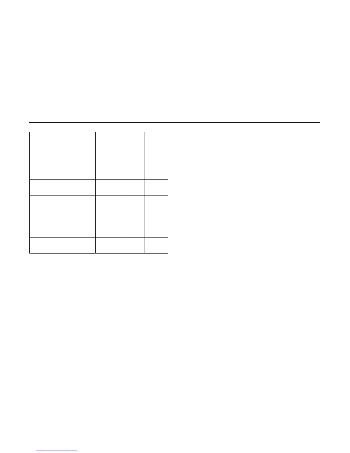
4.2 Vorbeugende Wartung
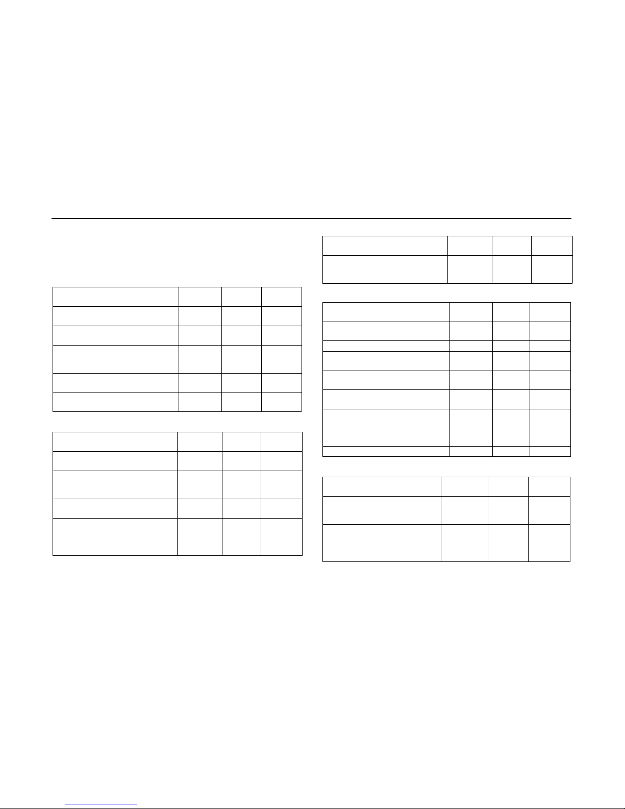
Die hier beschriebenen Maßnahmen der vorbeugenden Wartung betreffen
normale Betriebsbedingungen. Bei höherer Beanspruchung und Fahrten in
stark belasteter Luft, müssen die Maßnahmen in entsprechend kürzeren Abständen durchgeführt werden.
Kühlkreislauf Monatlich alle 3
Monate
Jährlich
Manometer anschließen, Drücke
und Temperatur messen
X
Kältemittelstand nach 15 Minuten
Betrieb überprüfen
X
Sichtkontrolle auf Abnutzung und
Verschleiß von Leitungen und
Schläuchen
X
Sichtkontrolle auf Leckage von Öl
und Kältemittel
X
Überprüfen der Öffnungs- und
Schließdrücke der Druckschalter
X
Verdichter / Magnetventil Monatlich alle 3
Monate
Jährlich
Sichtkontrolle auf Verschleiß des
Magnetventils
X
Sichtkontrolle auf Zustand, Spannung und Ausrichtung der Verdichterriemen
X
Verdichter und Kompressorkupplung reinigen
X
Widerstand und Strom der
Kompressorkupplungsspule
messen
X
Verdichter / Magnetventil Monatlich alle 3
Monate
Jährlich
Ölstand des Verdichters nach 15
Minuten Betrieb überprüfen
(3/4 zu 1/4 des Schauglases)
X
Struktur Monatlich alle 3
Monate
Jährlich
Sichtkontrolle auf lose, beschädigte
oder gebrochene Teile
X
Luftfilter reinigen oder auswechseln X
Kondensatablauf des Verdampfers
reinigen
X
Verflüssiger mit Neutralseife reinigen
X
Verdampfer mit Neutralseife reinigen
X
Alle Schrauben des Kompressorträgers und des Anlagenträgers
nachziehen, dabei Drehmoment
berücksichtigen
X
Überprüfen der Haubenbefestigung X
Elektrik Monatlich alle 3
Monate
Jährlich
Sequenz des Thermostats überprüfen (Kühlung / Lüftung
Kühlung / Heizung)
X
Generator überprüfen X
Page 10
CC 145
8
Anmerkung:
Wir empfehlen die vorliegende Tabelle zur Aufstellung eines eigenen,
regelmäßigen Wartungsplans Ihrer Fahrzeuge zu nutzen.
ACHTUNG
Die Reinigung des Umluftfilters und des Verflüssigers in der Klimaanlage
muss wöchentlich erfolgen.
Werden diese Intervalle nicht eingehalten, kann es als Fahrlässigkeit
gewertet werden und zum Erlöschen der Garantieansprüche führen.
Die Reinigung der Kanäle muss alle drei Monate ausgeführt werden,
gegebenenfalls auch in kürzeren Abständen, gemäß der Nutzung des
Klimaanlagensystems, der Anzahl an beförderten Personen und der Qualität
der Luft, in der das Fahrzeug genutzt wird.
Die Reinigung liegt ausschließlich in der Verantwortung des Fahrzeugbesitzers, er trägt die Verantwortung für die Qualität der Luft, der die Passagiere
ausgesetzt sind.
Elektrik Monatlich alle 3
Monate
Jährlich
Klemmen des Leistungskabels
am Generator, Hauptsicherung
und Elektroanschlüsse überprüfen
X
Sichtkontrolle auf Zustand,
Spannung und Ausrichtung der
Generatorriemen
X
Generator und elektrische Anschlüsse reinigen und auf Korrosion überprüfen
X
Drehzahlen und Luftdurchlass der
Verdampfergebläse und Verflüssigergebläse überprüfen
X
Stromaufnahme der Verflüssigergebläse und Verdampfergebläse überprüfen
X
Bedienteil und Sensor des Thermostats mit Druckluft reinigen
X
Alle Drähte, Stecker und Anschlüsse auf Beschädigungen
und Korrosion überprüfen
X
Page 11
CC 145
9
5 Technische Daten
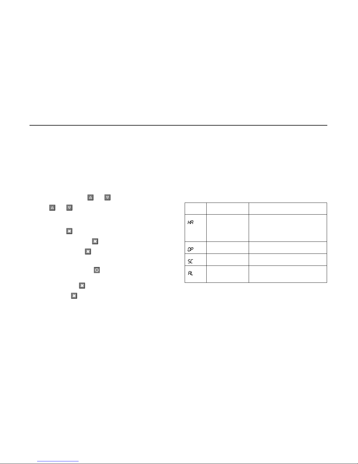
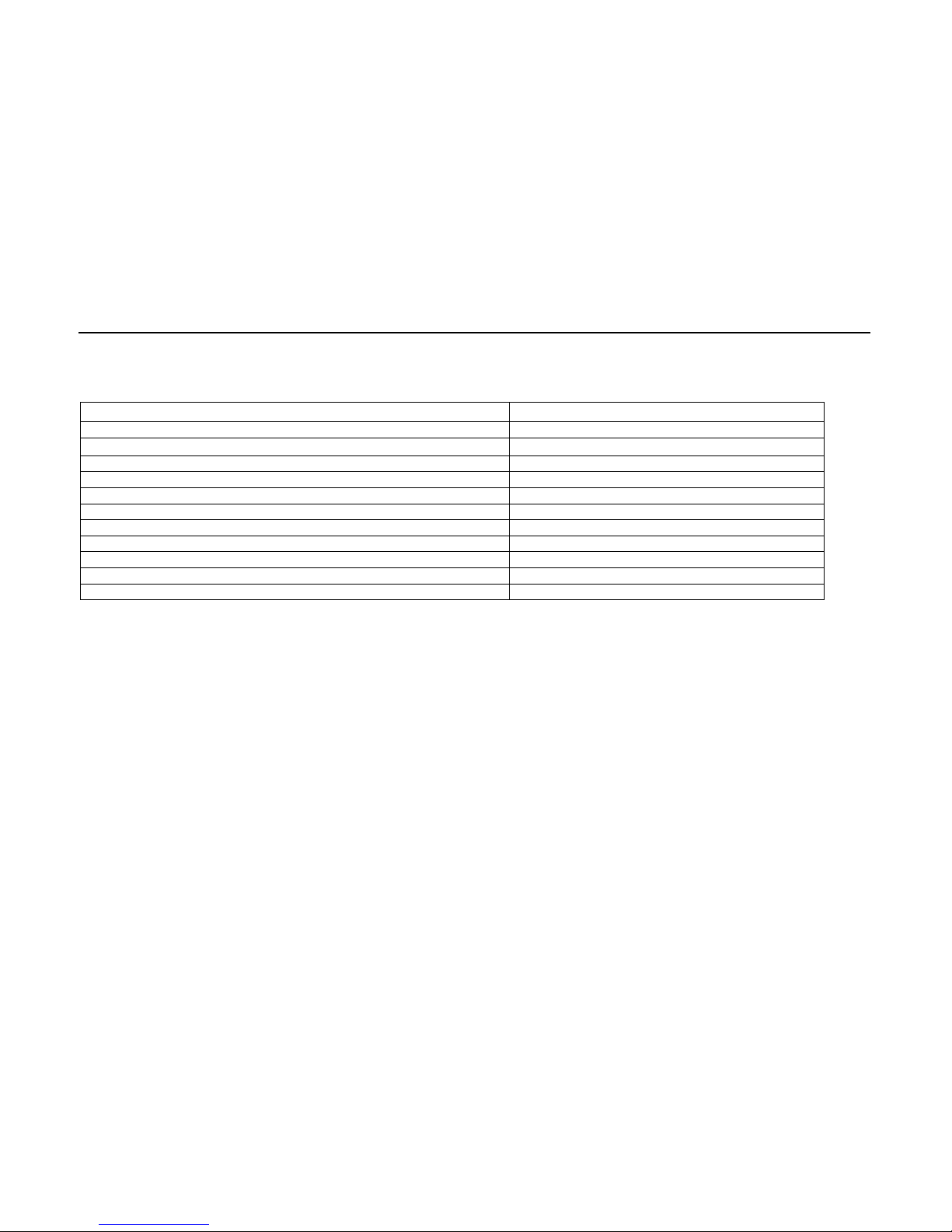
Die folgende Abbildung listet die technischen Daten der Klimaanlage auf.
CC 145
Kühlleistung max. (kW) 12
Kühlleistung nominal (kW) 9.5
Abmessungen L x B x H (mm) 1740 x 1200 x 200
Gewicht (kg) 67
Luftdurchsatz (freiblasend, in m³ / h)
2040
Versorgungsspannung (V) 12 / 24
Stromverbrauch bei 12 V / 24 V (A) 90 / 45
Sorte Kältemittel R134a
Füllmenge Kältemittel (kg) Richtwert 3.7
Anzahl Verdampfergebläse 2
Anzahl Verflüssigergebläse 2
Abb. 5 Technische Daten
Page 12
CC 145
10
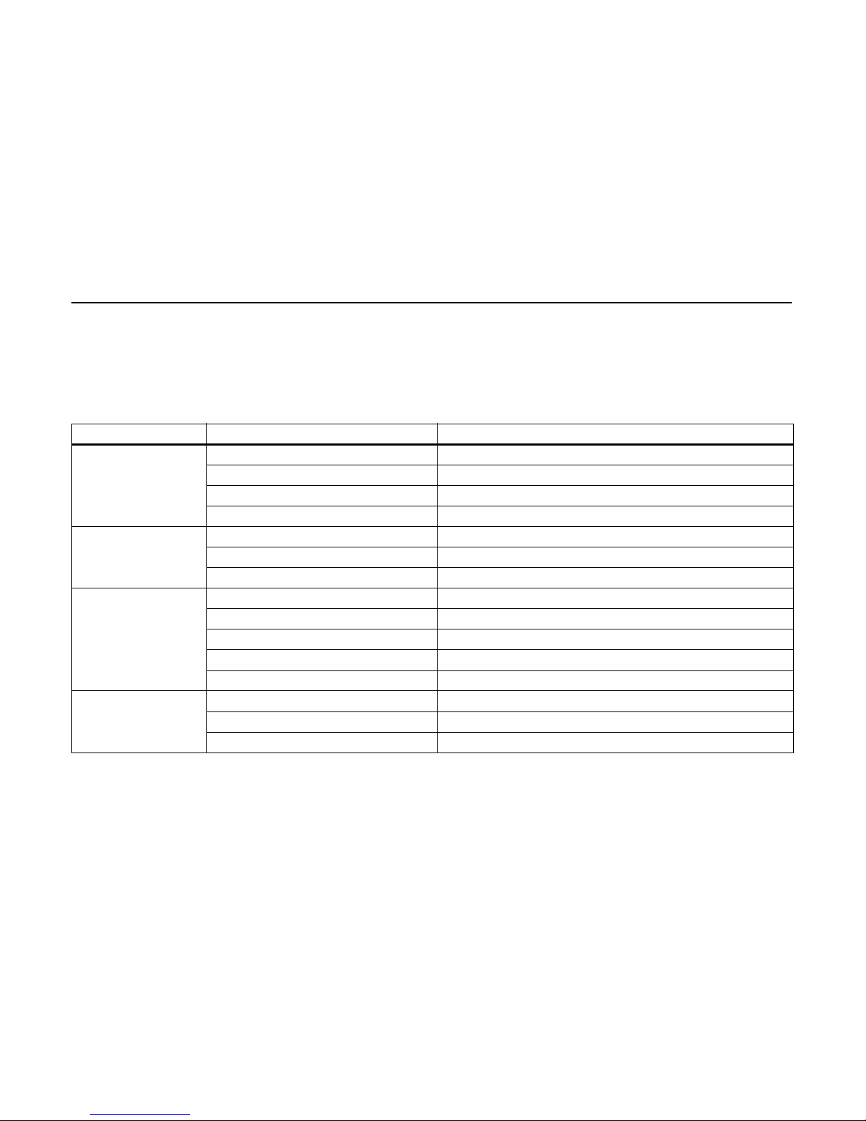
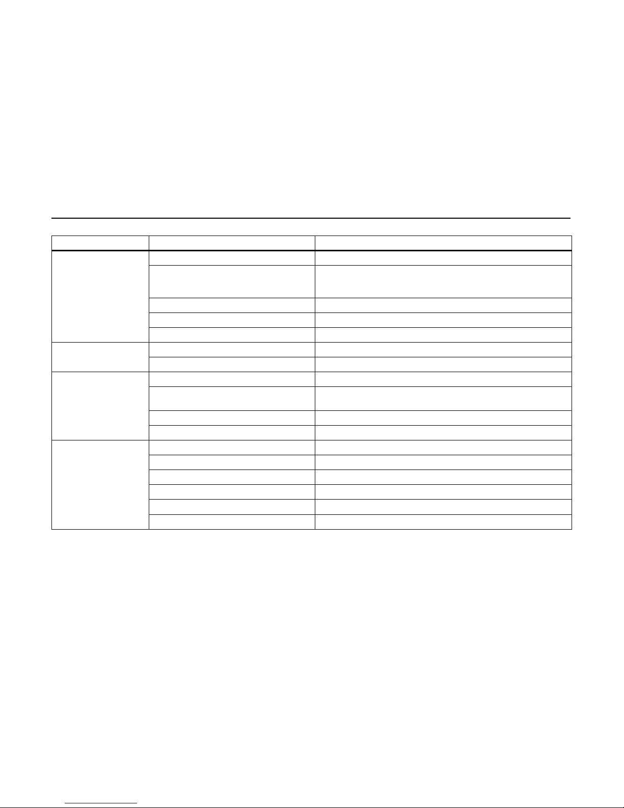
6 Fehlersuche und -beseitigung
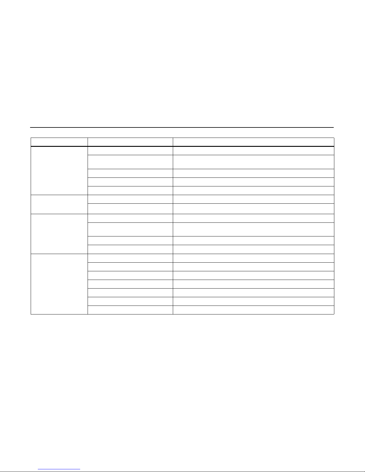
Für die Fehlersuche und -beseitigung listet die folgende Abbildung in Tabellenform mögliche Störungsanzeichen und die entsprechenden Maßnahmen zur
Fehlerbeseitigung, um die einwandfreie Funktion der Anlage wieder herzustellen, auf.
Störungsanzeichen Mögliche Ursache Maßnahmen
Verdichter arbeitet nicht Sicherung oder Relais defekt Sicherung oder Relais auswechseln
Kompressorkupplung durchgebrannt Kupplung auswechseln
Verdichter festgefressen Verdichter auswechseln
Niederdruckschalter offen Zu wenig Gas in der Anlage oder Niederdruckschalter defekt
Hochdruckschalter öffnet Zu viel Kältemittel Kältemittel in geeigneten Behälter ablassen
Verflüssiger verschmutzt Verflüssiger reinigen
Verflüssigergebläse laufen nicht Motor(en) auswechseln
Niederdruckschalter öffnet Zu wenig Kältemittel Auf Undichtigkeiten prüfen, Kältemittel auf den richtigen Stand nachfüllen
Expansionsventil verschmutzt oder schadhaft Expansionsventil auswechseln
Verdampfer verschmutzt Verdampfer reinigen
Luftfilter übermäßig verschmutzt Luftfilter auswechseln
Verdampfergebläse läuft nicht Verdampfergebläse auswechseln
Verflüssigergebläse läuft
nicht
Offene Verbindung in der Verkabelung Kabelbaum/Verkabelung instandsetzen
Verflüssigergebläse defekt Verflüssigergebläse auswechseln
Sicherung durchgebrannt oder Relais defekt Sicherung und/oder Relais auswechseln
Abb. 6 Störungsanzeichentabelle
Page 13
CC 145
11
Klimaanlage kühlt nicht
und Verdichter läuft ständig
Zu wenig Kältemittel Auf Undichtigkeiten prüfen, Kältemittel auf den richtigen Stand nachfüllen
Luft oder anderes Gas in der Anlage Vakuum in der Anlage wieder herstellen (mindestens 3 Stunden bei unter
10 mbar), Filtertrockner auswechseln und Kältemittel auf den richtigen Stand
füllen
Expansionsventil verschmutzt oder schadhaft Expansionsventil reinigen oder auswechseln
Verdampfer verschmutzt Verdampfer reinigen
Luftfilter verstopft Luftfilter reinigen oder auswechseln
Klimaanlage überkühlt und
Verdichter schaltet nicht ab
Falsche Temperatureinstellung Temperatureinstellung an der Bedientafel ändern
Temperaturfühler an falscher Stelle Temperaturfühler an geeigneter Stelle anbringen
Hochdruck zu hoch Zu viel Kältemittel Kältemittel auf richtigen Füllstand in einen geeigneten Behälter ablassen
Kältemittelfluss eingeschränkt Nach dem Grund suchen (Verdichterventil nicht ganz offen, Expansionsventil
blockiert, Filtertrockner blockiert, usw)
Verflüssigergebläse läuft nicht Siehe Fehleranzeichen "Verflüssigergebläse läuft nicht"
Verdampfer verschmutzt Verdampfer reinigen
Niedriger Saugdruck Zu wenig Kältemittel Auf Undichtigkeiten prüfen, Kältemittel auf den richtigen Stand nachfüllen
Luftrückstromtemperatur zu niedrig Temperaturfühler an geeigneter Stelle anbringen
Expansionsventil verschmutzt oder schadhaft Expansionsventil auswechseln
Verdampfermotor läuft nicht Verdampfermotor auswechseln
Luftfilter verschmutzt Luftfilter reinigen oder auswechseln
Verdampfer verschmutzt Verdampfer reinigen
Störungsanzeichen Mögliche Ursache Maßnahmen
Abb. 6 Störungsanzeichentabelle
Page 14

CC 145
12
7 Schaltpläne
7.1 Allgemeines
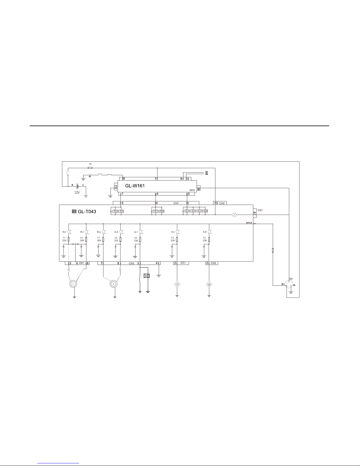
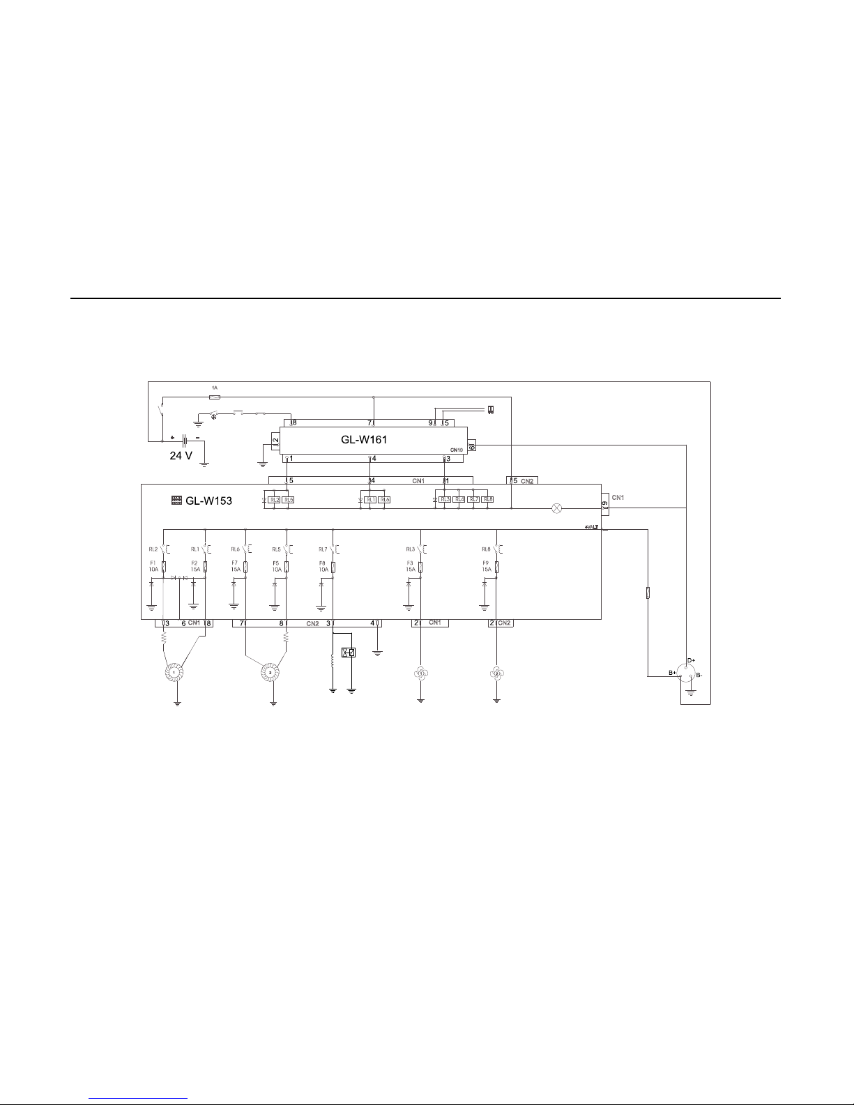
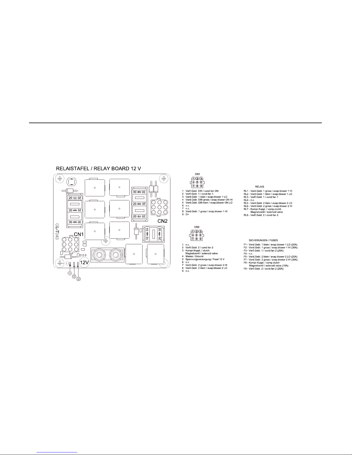
Die Abbildung 7 ab Seite 25 zeigt die Schaltpläne der Klimaanlage CC 145.
Bei Leitungen ohne Angabe der Stärke beträgt der Querschnitt 0,75 mm².
Page 15
CC 145
13
1 Equipment General Arrangement
1.1 Air conditioner CC 145
The air conditioner type CC 145 and its main components are shown
in Fig. 1.
Fig. 1 CC 145
Page 16
CC 145
14
2 Controls and Indicators
2.1 Control Panel
The air conditioner control panel has all controls and indicators for system
settings, mode switching and operational indications.
The control panel and its controls and indicators are shown in Fig. 2.
Fig. 2 Control Panel
Page 17
CC 145
15
2.2 Function of Controls and Indicators
The function of the controls and indicators is shown in Fig. 3.
Note
All keys have backlit red LED’s.
Index
Fig. 2
Control / Indicator Setting /
Indication
Function
1 Display oF Ignition on, system in standby for
activation by pressing AUTO key.
Ventilation only is possible by pressing
ventilation key.
Number or
Code
System in operation. Indication of
temperatures, ventilation speed, failure
codes and status information depending
on system operational mode and
indication selections. For details refer to
"Command Description".
2 Cooling ON/OFF
key
pressed Manually selection of cooling
mode ON /OFF.
3 A/C ON LED lit A/C mode is on, system operates in
climatisation mode.
Fig. 3 Function of Controls and Indicators
4 AUTO mode LED lit AUTO mode is on, system operates in
AUTO mode.
5 Ventilation speed
LO LED
lit Indication of ventilation speed LO
manually selected with ventilation key.
AUTO mode LED is off.
6 Ventilation speed
HI LED
lit Indication of ventilation speed HI
manually selected with ventilation key.
AUTO mode LED is off.
7 Key ventilation
speed
pressed Manual selection of blower speed LO
or HI with up / down keys to override
automatic AUTO mode ventilation speed.
Indicated at first.
8 DOWN key pressed Down control for system settings and
readings in the different operational
modes including testing and system status readouts.
9 UP key pressed Up control for system settings and read-
ings in the different operational modes including testing and system status
readouts.
Index
Fig. 2
Control / Indicator Setting /
Indication
Function
Fig. 3 Function of Controls and Indicators
Page 18
CC 145
16
3 Equipment Operation
3.1 Command Description - Normal Operation
3.1.1 Display
The two digit numeric display is used for informing the operator about the
selected set temperature.
3.1.2 Set-point
The set-point is the desired temperature inside the vehicle. To change the
set-point temperature one of the keys or have to be pressed.
The actual selected set point temperature blinks and may be adjusted by
pressing the or keys.
3.1.3 Ventilation mode
The ventilation function is activated by the key.
There are two operation speeds. Press the key once to select the LO
ventilation speed, press the key a second time to select the HI ventilation
speed.
A third time pressing switches off the ventilation mode.
The selected ventilation speed is indicated by LED (5) for LO ventilation
speed and LED (6) for HI ventilation speed.
3.1.4 Cooling mode
The set temperature is the desired room temperature within the vehicle.
With the vehicle ignition ON, the display will show to indicate standby for
A/C operation, which can then be activated by pressing the key and
selecting the desired set temperature. When AUTO mode is off, it is possible
to have just ventilation by pressing the key.
The cooling mode can be selected by pressing the key and starts the
system in AUTO mode. The system selects the required evaporator blower
speed automatically.
By pressing the key the evaporator blower speed can be manually set to
LO (1 time), HI (2 times) and back to AUTO mode (3 times).
The LED (3) illuminates, if the compressor clutch is closed.
If the compressor clutch is open, the LED (3) blinks.
To prevent short operation cycles of the compressor clutch, an interval of 30
seconds between ON and OFF is programmed.
3.2 Command Description - Failure Operation
3.2.1 Failure Operation - Control Panel Functions available
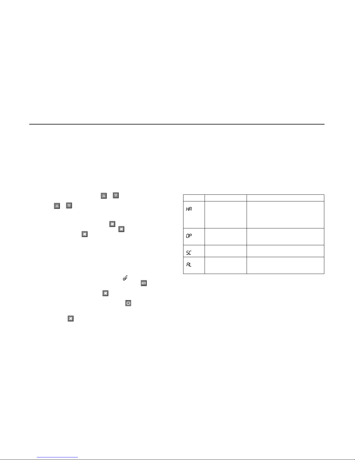
The system indicates failure codes on the display.
The following figure lists all possible failure codes and their meaning.
Failure Description Operational bahavior in fail condition
Pressure switch failure/
anti-icing thermostat
failure
Check pressure switch,
check anti-icing thermostat,
check evaporator,
check refrigerant pressure,
check evaporator blower
Temperature sensor
connection
interrupted
Check temperature sensor / wiring
Temperature sensor
short circiut
Check temperature sensor / wiring
Electrical power
failure
Check battery voltage,
check wiring,
check alternator
Fig. 4 Failure Code Indications
Page 19

CC 145
17
3.3 Electrical Malfunctions
The individual circuits are to be checked systematically in accordance with
the wiring diagram.
Preferably the plug connections and electrical components such as switches,
relays, etc. should be checked for conduction.
The following possible causes of malfunctions should always be checked first
so that they can be excluded as the cause of the problem:
- corroded plug contacts
- loose plug contacts
- corroded wires
- corroded battery terminals
- unfixed wires
- defective fuses
3.4 Malfunctions in the Air Conditioning System
The following malfunctions may occur in the air conditioning system and may
lead to a fault lockout of the system:
- activated ice-sensor
- activated high / low pressure switch
- defective compressor
- defective evaporator or condenser fans
- refrigerant loss due to leaks
- loaded air filter or dirty heat exchanger fins
- blocked refrigeration circuit (e.g. filter drier)
- defective expansion valve
3.5 Malfunctions in the Refrigeration Circuit
If malfunctions occur in the refrigeration circuit of the air conditioning system,
the system must be checked and properly repaired by an authorized air
conditioning service agent.
CAUTION
The refrigerant is not allowed to be released to the atmosphere
(8, CFC-Halon prohibitory Directive of 06.05.1991).
Check the refrigerant charge in the system.
- After the air conditioning system has been operating for approx. 5 min.
with the electromagnetic clutch activated and the engine running at rapid
idle, the refrigerant should flow through the sight glass without forming any
bubbles.
During the cold season:
- To prevent the shaft seal of the refrigeration compressor from drying out,
operate the air conditioning system for approx. 15 min. once a month at
ambient temperatures of min. > 8 °C.
The refrigerant receiver as well as all components of the air conditioning
system should be visually inspected during the maintenance activities.
Special attention should be directed to any signs of corrosion and mechanical
damage.
All components that are not in perfect condition must be replaced for safety
reasons.
CAUTION
The pressure vessels directive requires the operator to have the refrigerant
receiver checked by a qualified expert at regular intervals.
Note
To ensure trouble free operation of the air conditioner, the refrigeration oil and
the filter drier must be replaced 6 months after the initial operation of the
vehicle.
The filter drier should be replaced every year at the beginning of the season.
These activities are to be performed by an authorized qualified workshop,
which should also perform a functional check of the air conditioner as well as
a leak test.
Warranty claims can only be accepted if the claimant can prove that the
maintenance and safety instructions have been strictly observed.
Page 20

CC 145
18
4 Maintenance Activities
4.1 General
An air-conditioning system is - just as all the other parts of a vehicle subjected to constant mechanical strain and stress. To ensure a trouble-free
operation of the system and to avoid any damage to its parts, it is important
to perform all required service activities on the air-conditioning system by
trained and qualified personnel who are knowledgeable in the field of
refrigeration.
The proper handling of the system including proof of the service activities
record (completed maintenance and service schedule) is a prerequisite for
acceptance any warranty claims in the event of damage to parts subject to
maintenance.
Regardless of the maintenance intervals specified in the maintenance and
service schedule, all attachments of the unit and the connections of the
refrigerant lines must be checked for tightness within the first four weeks
following the initial start-up of the air-conditioning system or the vehicle.
Even if the air-conditioning system is not in operation, wear caused by normal
ageing or the strain and stress occurring during the driving operation of the
bus may occur on individual components. All checks listed in the
maintenance and service schedule have therefore to be performed
independently of the operation hours of the system.
Loss of refrigerant is possible even if the refrigerant connections are tight.
Due to the structure of the material of the refrigerant lines, these show a
diffusion rate the extent of which varies depending on the ambient
temperatures. In the event of a relatively high refrigerant loss within short
intervals, leaks in the system can be assumed.
During long term non-use the air-conditioning system should be operated for
about 15 minutes at least once a month in order to prevent the shaft seals of
the refrigerant compressor from hardening. A requirement for this is a
minimum outside temperature of > 8 °C.
The drive pulley of the electromagnetic clutch is continuously rotating when
the vehicle engine is in operation. Bearing wear or possible damage to the
clutch therefore occurs practically independently of the operating time of the
air-conditioning system. It is therefore imperative that the clutch must be
checked for correct lubrication, belt tension etc., in accordance with the
maintenance instructions.
CAUTION
- The refrigerant receiver is subject to the Pressure Equipment Directive.
Check the refrigerant receiver every 6 months for cracks, corrosion and
other damage.
- The receiver must be replaced in the event of cracks, mechanical damage
or corrosion.
- The maintenance intervals indicated in the maintenance and service
schedule are based on operation hours of the vehicle, with the exception of
the compressor assembly, which are based on the air-conditioning unit's
hours of operation.
- These time intervals are empirical values that may vary widely depending
on the type of system and type of bus concerned.
Page 21
CC 145
19
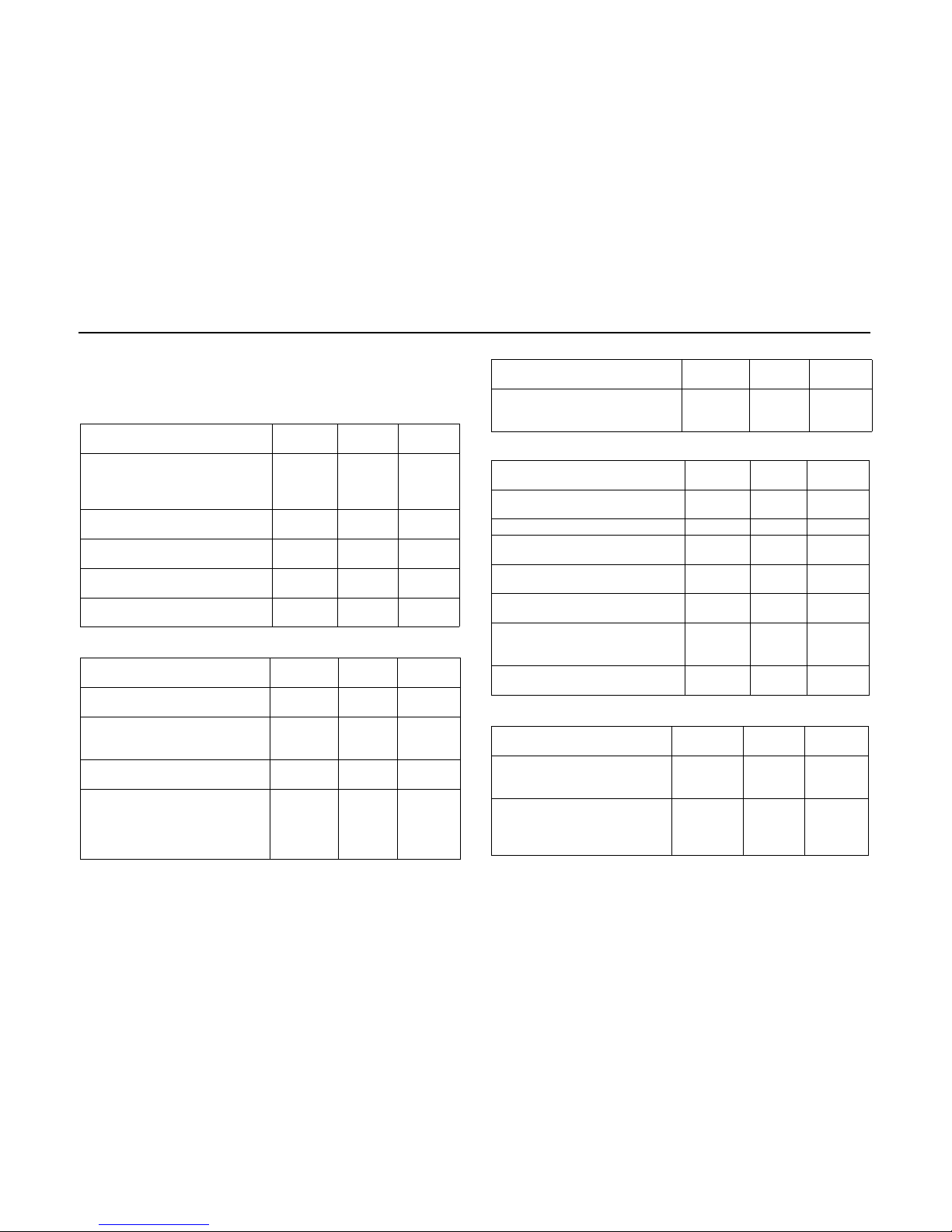
4.2 Preventive Maintenance
The below listed actions are performed for normal operation.
If the system will be operated with high workload or in areas with air contamination the actions have to be carried out in shorter time periods.
Cooling circuit every
month
all 3
months
every
year
Use a pressure gauge,
check refrigerant pressure
check refrigerant temperatures
X
After 15 minutes operation, check
sight glass for bubbles
X
Do a visual examination of pipes and
hoses
X
Do a visual examination for signs of
leakage of oil and refrigerant
X
Check the open and close pressure
of the pressure switches
X
Compressor / compressor clutch every
month
all 3
months
every
year
Do a visual examination of the
compressor clutch
X
Do a visual examination for
condition, tension and alignment of
the V-belt
X
Clean the compressor and the
compressor clutch
X
Measure the coil resistance and the
electrical power consumption of the
compressor clutch
X
Compressor / compressor clutch every
month
all 3
months
every
year
After 15 minutes operation, check
the oil level of the compressor
(3/4 to 1/4 of the sight glass)
X
Structure every
month
all 3
months
every
year
Do a visual examination for loose or
damaged parts
X
Clean or replace the air filter X
Clean the evaporator condensate
drain
X
Clean the condenser with neutral
soap
X
Clean the evaporator with neutral
soap
X
Tighten all bolts of the compressor
bracket and the mounting of the
roof unit with correct torque
X
Check the attaching points of the
cover
X
Electrical system every
month
all 3
months
every
year
Check the sequence of the
thermostat (cooling / ventilation cooling / heating)
X
Check the alternator X
Page 22
CC 145
20
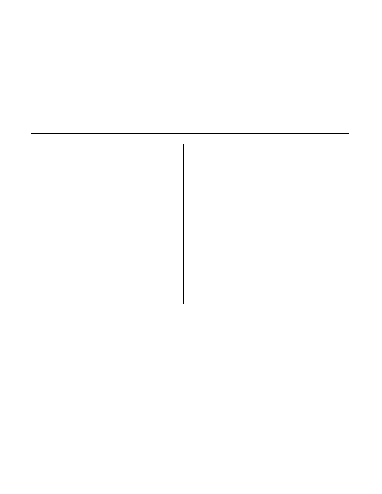
Note:
We propose to use the tables for the preparation of maintenance plans for
your fleet.
CAUTION
The cleaning of the air filter and the condenser has to be carried out each
week.
To increase these intervals is careless and can cause loss of warranty claim.
The cleaning of the air ducts has to be carried out every 3 months, if necessary in shorter intervals, depending on the operating times of the system, the
number of passengers and the quality of the outside air.
Responsible for the cleaning is the owner of the vehicle, he is also
responsible for the quality of the air in the passenger compartment.
Electrical system every
month
all 3
months
every
year
Check the connections of the
electrical power cable at the
alternator for condition, damage
and corrosion
Check the main fuse for condition,
damage and corrosion
X
Do a visual examination for
condition, tension and alignment
of the alternator V-belt
X
Clean the alternator and the
electrical connections
Check the alternator and the
electrical connections for
corrosion
X
Check the evaporator blowers
and the condenser fans for
rotational speed and free air flow
X
Check the evaporator blowers
and the condenser fans for
electrical power consumption
X
Clean the control panel and the
thermostat sensor with
pressurized air
X
Check all wires, connectors and
electrical connections for
condition, damage and corrosion
X
Page 23
CC 145
21
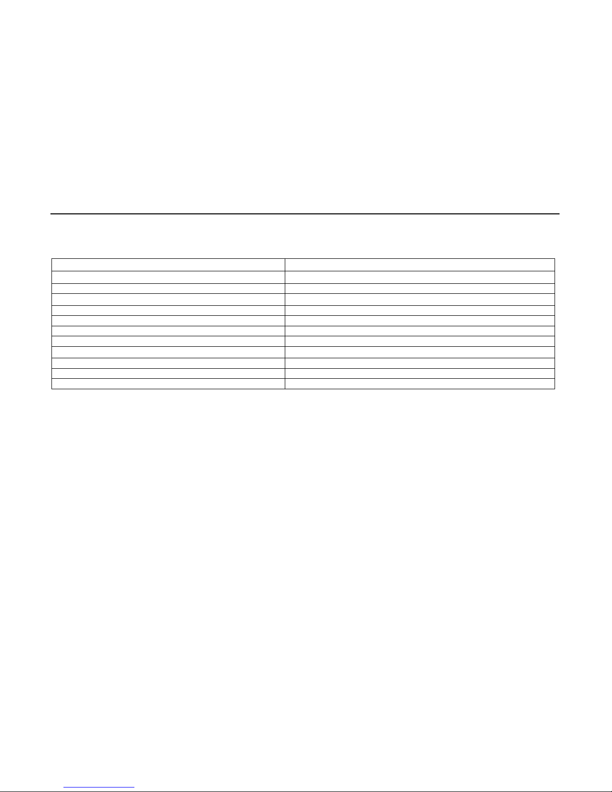
5 Technical Specification
The following figure lists the main specification of the air condition system.
CC 145
Max. cooling capacity (kW) 12
Cooling capacity (kW) 9.5
Dimensions Length x Width x Height (mm / in.) 1740 x 1200 x 200 / 68.5 x 47.3 x 7.9
Weight (kg/lbs) 67 / 147.7
Air volume (free, m³ / h) 2040
Supply voltage (VDC) 12 / 24
Electrical power consumption at 12 VDC / 24 VDC (A) 90 / 45
Refrigerant type R134a
Number of evaporator blowers 2
Number of condenser fan 2
Fig. 5 Technical Data
Page 24
CC 145
22
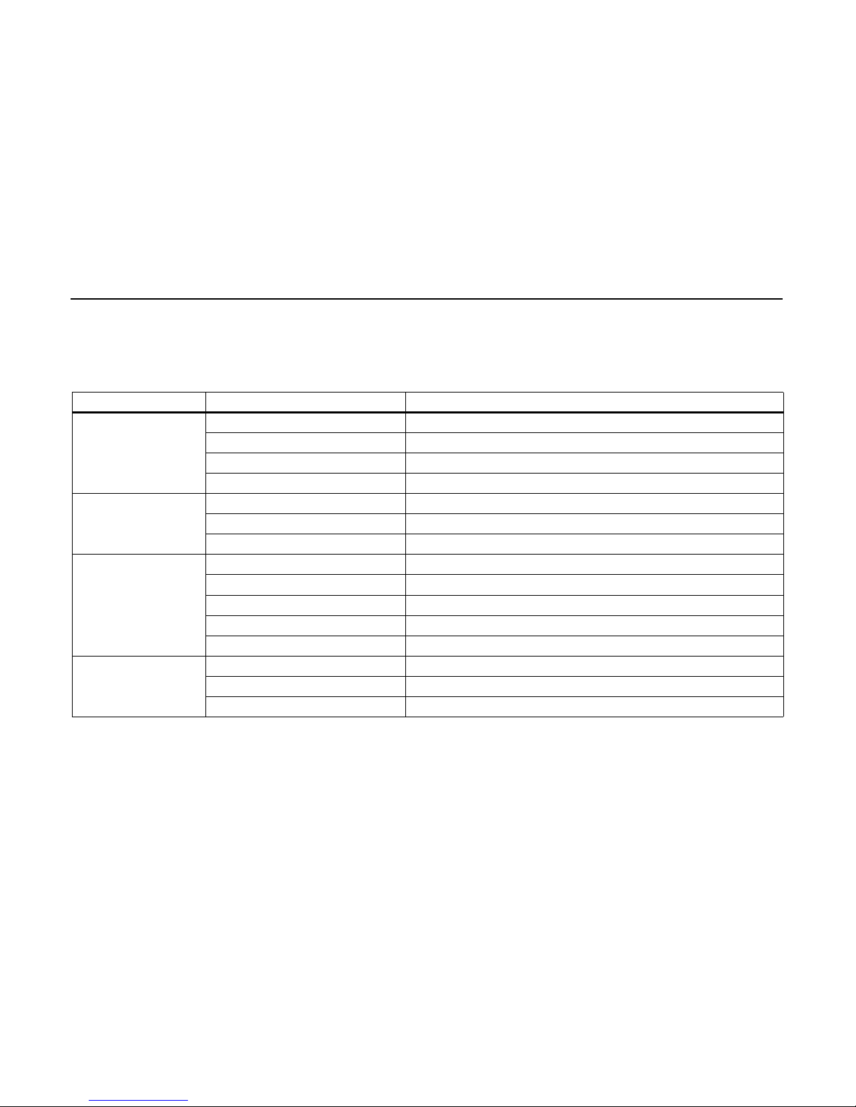
6 Failure Diagnosis Table
For troubleshooting the following figure lists possible malfunctions and
symptoms and the remedial action to be taken to restore the system's
serviceability.
Symptoms Probable cause Solution
Compressor does not work Fuse or relay defective Replace fuse or relay
Magnetic clutch burned Replace clutch
Compressor blocked Replace compressor
Low pressure switch open Lack of gas on system or defective low pressure switch
HP switch opens Excessive refrigerant Drain and collect excess refrigerant
Condenser coil is dirty Clean the coil
Condenser motor/motors stopped Replace motors
LP switch opens Lack of refrigerant Check for leakage, refill to correct amount
Dirty or defective expansion valve Replace the valve
Dirty evaporator coil Clean the coil
Excessively contaminated air filter Replace the filter
Evaporator ventilator is stopped Replace the evaporator fan
Condenser motor is
stopped
Electric wiring connections with no contact Repair wiring harness
Condenser motor is stopped Replace condenser motor
Burned fuse or defective relay Replace fuse and/or relay
Fig. 6 Failure Diagnosis Table
Page 25
CC 145
23
AC does not cool down and
the compressor remains on
Lack of refrigerant Check for leakage, fill to correct amount
Air or other gas in the system Draw a vacuum (min. 3 hours below 10 mbar) replace filter drier, fill to correct
amount
Dirty or defective expansion valve Replace the valve
Dirty evaporator coil Clean the coil
Air filter dirty Clean or replace filter
It cools down too much and
the compressor does not
turn off
Incorrect temperature selection Adjust the temperature on the control panel
Temperature sensor badly placed Place the sensor appropriately
High discharge pressure Excess refrigerant in the system Drain and capture refrigerant, fill to correct amount
Refrigerant flow obstructed Check for restriction (compressor valve partially closed, expansion valve blocked,
filter drier blocked, etc.)
Condenser motor is stopped Refer to symptom "Condenser motor is stopped“
Dirty condenser coil Clean and wash
Low suction pressure Lack of refrigerant Check for leakage, fill to correct amount
Air return temperature is too low Place the temperature sensor at the most appropriate position
Dirty or defective expansion valve Replace the valve
Evaporator motor is stopped Replace motor
Restriction in the system Eliminate
Loaded air filter Clean or replace filter
Dirty evaporator coil Clean coil
Symptoms Probable cause Solution
Fig. 6 Failure Diagnosis Table
Page 26

CC 145
24
7 Wiring Diagrams
7.1 General
The figure 7, starting on Page 25, shows the wiring diagrams of the CC 145
air conditioning system.
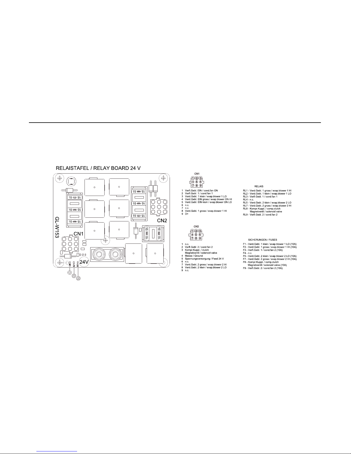
Wirings without cross section have 0,75 mm².
Page 27
CC 145
25
Abb. 7 Schaltplan / Wiring diagram 12 V (Seite/Page 1 von/of 4)
SOLENOID VALVE
COMPR. CLUTCH
Page 28
CC 145
26
Abb. 7 Schaltplan / Wiring diagram 24 V (Seite/Page 2 von/of 4)
SOLENOID VALVE
COMPR. CLUTCH
Page 29
CC 145
27
Abb. 7 Relaistafel / Relay board 12 V (Seite/Page 3 von/of 4)
Page 30
CC 145
28
Abb. 7 Relaistafel / Relay board 24 V (Seite/Page 4 von/of 4)
 Loading...