

Page 1
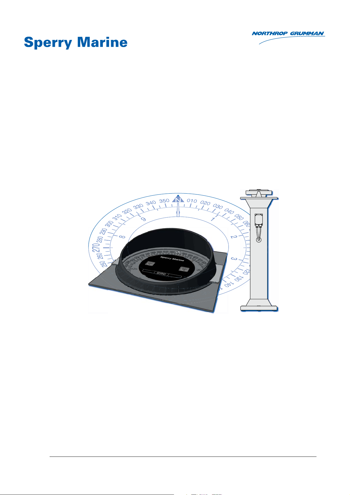
Operation, Installation and Service Manual
Original Documentation / Keep for Future Reference
Analogue Compass Repeaters
Types 5016-CA, 5016-CB, 5016-CC, 5016-CD
with RS-422 Serial Interface
056376/A; 05016-0128-02, 03 Feb 2015
Northrop Grumman Sperry Marine B.V. (Representative Office)
Woltmanstr. 19 • D-20097 • Hamburg, Germany
Tel.: +49-40-299 00-0 • Fax: +49-40-299 00-146 • E-mail: [email protected]
Page 2

056376/A Analogue Compass Repeaters
© 2015 Northrop Grumman Sperry Marine B.V.
This document and the information herein is the intellectual property of Northrop Grumman
Sperry Marine B.V. [NGSM BV] and it’s associate companies and may not be copied, reproduced
or translated without the express permission of NGSM BV.
Specifications were correct at time of press but may be varied in accordance with NGSM BV’s
policy of continuous product development.
Any technical content should be verified with NGSM BV.
Sperry Marine, with major engineering and support offices in New Malden, England, and
Hamburg, Germany, is part of the Northrop Grumman Navigation & Maritime Systems Division
N&MSD.
Rev. Date Remarks
A 03 Feb 2015 Initial release; this manual applies for the analogue compass repeaters
types 5015-CA, -CB, -CC and -CD.
Manual 056359 remains valid for the now discontinued types
5016, 5016-AA, -AB and -AC.
Page 3

Analogue Compass Repeaters 056376/A
Contents
Safety Instructions
Safety Notice Conventions ....................................................................... vii
General Safety Information for the Operator ........................................ viii
General Safety Information for Service Personnel ................................... x
Chapter 1: Introduction
1.1 System Description................................................................................... 1-1
Intended Use ............................................................................................. 1-1
Not Intended Use ...................................................................................... 1-1
1.2 Design and Main Features........................................................................ 1-2
1.3 Functional Description.............................................................................. 1-3
1.4 Compass Repeater Type Variants ............................................................ 1-4
Bearing Repeater....................................................................................... 1-4
Steering Repeater...................................................................................... 1-4
Magnetic Heading Repeater ..................................................................... 1-4
Bulkhead Repeater .................................................................................... 1-5
1.5 Accessories ................................................................................................ 1-5
Bearing Repeater Stand and Brackets ..................................................... 1-5
Bulkhead Repeater Bracket....................................................................... 1-5
Connection Box ......................................................................................... 1-6
Azimuth Device PV 23 ............................................................................... 1-6
Telescopic Alidade..................................................................................... 1-6
1.6 Technical Data............................................................................................ 1-7
1.7 Declaration of Conformity ...................................................................... 1-15
Chapter 2: Operation
2.1 Readout Elements, Indicators and Controls ........................................... 2-1
2.2 Powering up the Repeaters ...................................................................... 2-2
2.3 Data Protocol and Source Detection ....................................................... 2-2
2.4 Reading off Heading and Source Indication ........................................... 2-3
2.5 Adjusting the Illumination Brightness .................................................... 2-4
2.6 Synchronizing the Compass Cards.......................................................... 2-5
2.7 Initiating the Self Test............................................................................... 2-5
2.8 Bearing Repeater Capacitive Keys ........................................................... 2-5
2.9 Taking Bearings with the Azimuth Device PV 23 ................................... 2-6
Chapter 3: Error Indication
3.1 Error Blink Codes....................................................................................... 3-1
Heading Timeout with flashing Source Indicator................................... 3-2
iii
Page 4

056376/A Analogue Compass Repeaters
Chapter 4: Preventive Maintenance
4.1 Maintenance by Shipboard Personnel .................................................... 4-1
Maintenance of externally installed Bearing Repeater .......................... 4-2
Chapter 5: Installation
5.1 Bearing Repeater....................................................................................... 5-1
Installing Bearing Repeater with Bearing Stand ..................................... 5-1
Installing Bearing Repeater with Bearing Bracket ..................................5-4
Installing Bearing Repeater with Adjustable Bearing Bracket ............... 5-6
5.2 Steering Repeater / Magnetic Heading Repeater .................................. 5-8
5.3 Bulkhead Repeater .................................................................................. 5-10
Chapter 6: Configuration
6.1 Using the Default Configuration .............................................................. 6-1
6.2 Configuring the Analogue Repeater with SUSI...................................... 6-1
6.3 Configuration Parameters ........................................................................ 6-6
RCS Type .................................................................................................... 6-7
Protocol Type ............................................................................................. 6-8
Baudrate..................................................................................................... 6-8
Gyro Selection ........................................................................................... 6-9
Magnetic Selection .................................................................................... 6-9
Status Selection....................................................................................... 6-10
Dimming Selection .................................................................................. 6-10
Dimming Group ID .................................................................................. 6-10
Dimming Offset ....................................................................................... 6-11
6.4 Dimming Values ...................................................................................... 6-12
Adjusting Dimming Values ..................................................................... 6-12
Serial Dimming Command Evaluation .................................................. 6-13
Chapter 7: Troubleshooting
7.1 Basic Service Checks ................................................................................ 7-1
All repeater types 5016-CA, -CB, -CC, -CD ............................................... 7-1
All repeaters, except bearing repeater, type 5016-CA ............................ 7-2
7.2 Viewing Error Information in SUSI .......................................................... 7-3
Analogue Repeater Error Page ................................................................. 7-3
Error IDs and Descriptions........................................................................ 7-4
7.3 Location of Parts on the Analogue Repeater PCB.................................. 7-6
Terminal Boards and Connectors............................................................. 7-7
Diagnostic LEDs......................................................................................... 7-7
Chapter 8: Corrective Maintenance
8.1 Updating the Repeater’s Firmware.......................................................... 8-1
Update Procedure...................................................................................... 8-2
iv
Page 5

Analogue Compass Repeaters 056376/A
Abbreviations
Appendix
A Setup and Configuration Tables
B Drawings
v
Page 6

056376/A Analogue Compass Repeaters
vi
Page 7
Analogue Compass Repeaters 056376/A
DANGER
WARNING
CAUTION
Note
DANGER
CAUTION
Safety Instructions
Safety Notice Conventions
The following safety notice conventions are followed throughout this
manual:
A Danger notice contains an operating or maintenance procedure, practice, condition, statement, etc., which, if not strictly observed, will
result in injury or death of personnel.
A Warning notice contains an operating or
maintenance procedure, practice, condition,
statement, etc., which, if not strictly observed,
could result in injury or death of personnel.
A Caution notice contains an operating or maintenance procedure, practice, condition, statement, etc., which, if not strictly observed, could
result in damage to, or destruction of equipment.
A Note contains an essential operating or maintenance procedure, condition or statement,
which is considered important enough to be
highlighted.
Special safety symbols may be used in this
manual to indicate:
Danger: Risk of electrical shock.
Caution: Components are sensitive to electro-
static discharge.
vii
Page 8
056376/A Analogue Compass Repeaters
WARNING
WARNING
WARNING
WARNING
WARNING
Note
General Safety Information for the Operator
Risk of Deviation
Never rely on the heading indication of an analogue compass repeater
alone to navigate a vessel or to perform other safety-critical operations.
The analogue repeater is an indicator only and will indicate ship’s heading as long as it receives formally valid data. It does not apply any filtering or plausibility checks of the incoming data.
Loss of data supply will result in a visual error indication but will not
raise an audible alarm.
Always confirm the plausibility of the heading indication at the repeater
against the respective source which generates the heading data.
In safety-critical operations, regularly check the data source and the
repeater’s indication against all available aids to navigation.
Risk of using magnetic heading data for steering
The magnetic heading repeater is equipped with a removable cover, hiding the compass card when navigating the vessel under normal use, as
the magnetic heading repeater is only classified for steering purposes in
case of emergency with other heading sources not available.
Never remove the cover from the magnetic heading repeater when navigating the vessel under normal use, to avoid steering the vessel mistakenly by magnetic compass heading.
Risk of using invalid heading data
The heading indication at the repeater is only valid if the error indicator
is off and exactly one of the source indicators is permanently lit.
In case the error indicator in on and one or all of the source indicators
are flashing the heading indication of the repeater must be considered
as invalid and the heading data must not be used for steering the vessel.
Risk of injury
Permanent eye damage may result, when looking directly at the sun or
at its reflection in the black azimuth mirror when using the azimuth
device PV 23.
The PV 23 is not suited for taking the azimuth of the sun itself, as the
anti-glare filters do not sufficiently block out direct sunlight.
Never look directly at the sun or at its reflection in the black azimuth mirror when using the azimuth device PV 23.
Risk of freeze
The bearing repeater 5016-CA is equipped with capacitive keys, sensitively reacting to the fingers skin resistance which will not function
when touched with gloves.
In case of minus temperatures always be extremely careful not to touch
the metal housing of the bearing repeater to avoid freeze of hands and
fingers.
viii
The capacitive keys of the bearing repeater 5016-CA are sensitive against
surface water, e.g. remaining rain drops, which may result in random
changing of the illumination brightness.
This effect does not have any impact on the functionality or handling of
the capacitive keys.
Page 9
Analogue Compass Repeaters 056376/A
CAUTION
CAUTION
CAUTION
CAUTION
CAUTION
Note
Note
Risk of damage though solar radiation
The bearing repeater 5016-CA is equipped with a cover plate for protection against solar radiation.
It is recommended to always protect the bearing repeater with the cover
plate when not in use.
Risk of damage
The cover plate, protecting the bearing repeater 5016-CA against solar
radiation, must never be touched with tools to avoid any damage.
Always install and remove the cover plate with bare hands only.
Risk of damage through wrong cleaning agent
The front plates of the compass repeaters are sensitive against aggressive cleaning agents as organic solvents or acetone.
Do not clean the front plate with organic solvents, acetone or any other
aggressive cleaning agent.
Use only water and soap or a mild detergent to clean the front plate.
Risk of unnecessary wear
The bearing repeater 5016-CA can optionally be equipped with a watertight plastic cover for protection against environmental conditions.
It is recommended to always protect the bearing repeater with the plastic
cover when not in use.
Risk of damage
The prismatic azimuth device PV23 and the telecopic alidade are not
designed to stay permanently mounted on the bearing repeater.
Leaving the PV23 or the alidade on the bearing repeater after usage, will
cause wear and damage to the equipment.
Always remove the PV23 or the alidade from the bearing repeater and
store it carefully away in its storage box.
The repeater compasses do not possess an audible alarm indicator.
Sperry Marine Service:
In case of service refer to www.sperrymarine.com/offices for a list of
all Sperry Marine Offices and Service Agents worldwide.
ix
Page 10
056376/A Analogue Compass Repeaters
CAUTION
CAUTION
CAUTION
CAUTION
CAUTION
CAUTION
CAUTION
General Safety Information for Service Personnel
Risk of wrong installation
Wrong positioning of the bearing stand will obstruct to take bearings.
Always make sure that the bearing stand is so positioned that the vessel’s superstructure does not unduly obstruct the view of the horizon.
In case one bearing stand does not allow to take bearings in a full circle
of 360°, a second bearing stand must be installed for compensation.
Risk of damage
The compass repeaters are heavy instruments. The compass repeater
cables are not designed for holding the repeater just with the cable.
Never hold or transport the repeater on the cable alone when installing
or wearing a compass repeater.
Risk of damage
The bearing repeater is a heavy instrument.
To avoid any damage during installation of the bearing repeater into the
gimbal ring, the installation should be carried out by two service persons.
Risk of malfunction
Do not lengthen the cable between the bulkhead repeater and the connection box as the USB service port will not work reliably.
If the connection box cannot be installed at an accessible location close
to the repeater, it will be required to unmount and disassemble the
repeater to gain access to the internal USB receptacle when configuring
or servicing the device.
If the repeater cable is connected directly to shipside terminals, the external USB port may not be used and its four wires must be connected to
blind terminals.
Risk of damage through unauthorized service
The housing of the bearing repeater 5016-CA is designed for increased
watertightness and shall therefore not be opened in the field.
Opening the housing in the field will diminish the watertightness and
may lead to condensation forming on the inside surfaces, especially the
top glass, at a later point in time.
Never open the bearing repeater housing in the field.
Always return a defective bearing repeater to Sperry Marine.
Risk of damage through unauthorized service
The analogue compass repeaters are complex electronic devices, which
are not serviceable in the field down to the level of individual circuit components.
Defective units must be sent back to Sperry Marine for repair.
x
Risk of damage of electrostatic-discharge-sensitive components
The analogue compass repeaters contain electrostatic sensitive components. Electrostatic discharge may permanently damage components.
When servicing an analogue compass repeater, take precautions to prevent electrostatic discharge. Avoid touching any of the electronic circuitry.
Page 11

Analogue Compass Repeaters 056376/A
CAUTION
Note
Note
Risk of parameter settings loss
It cannot be guaranteed that the repeater’s configuration parameter settings are left intact during a firmware update.
Before updating firmware, record all parameter settings to be able to reenter them manually, if required.
The analogue compass repeaters are serviced and configured using the
Sperry Universal Setup Instrument (SUSI).
This tool is provided to authorized service personnel only and is generally not available to end-customers.
Exact voltage levels must be checked with a voltmeter true RMS.
The data content on serial I/O lines must be checked with the aid of suitable analysing tools, such as PC-based protocol interpreters or terminal
programs.
xi
Page 12

056376/A Analogue Compass Repeaters
xii
Page 13

Analogue Compass Repeaters 056376/A
Chapter 1: Introduction
1.1 System Description
Intended Use
The analogue compass repeaters are remote heading indicators which
display ship’s heading (secondary heading data), provided by a connected gyrocompass as active heading source (primary heading data),
and must only be operated from appropriately trained and educated
personnel familiar with all mandatory safety and operating procedures.
The prismatic azimuth device PV23 is a classified compass bearing
device designed for usage together with the bearing repeater 5016-CA.
Not Intended Use
The analogue compass repeaters are not allowed to be used for the navigation of inland water vessels and river boats. Any exception to this
restriction must be regulated by specific certification of an entitled
organisation or administration, for further details see certification information under ‘Design and Main Features” on page 1-2 and ‘Declaration
of Conformity” on page 1-15.
The magnetic heading repeater, type 5016-CC, is only classified for steering purposes in case of emergency when the gyrocompass(es) as primary heading source(s) are not available and must not be used for
navigating the vessel under normal conditions.
The telescopic alidade, stock no 60280, is not type approved as compass
bearing device, therefore it cannot be used to fulfil the carriage requirements.
System Description 1-1
Page 14

056376/A Analogue Compass Repeaters
1.2 Design and Main Features
The analogue compass repeaters are remote heading indicators which
display ship’s heading (secondary heading data), provided by a connected gyrocompass as active heading source (primary heading data),
using a rotating compass card assembly.
The repeaters are available in four type variants:
• Bearing Repeater, Type 5016-CA
• Steering Repeater, Type 5016-CB
• Magnetic Heading Repeater, Type 5016-CC
• Bulkhead Repeater, Type 5016-CD
The analogue compass repeaters have been type-approved by Germanischer Lloyd (GL), in accordance with the Maritime Equipment Directive
(MED) 96/98/EC as amended, as
gyrocompass accessory equipment
in the type approval certificates of the
Sperry Marine gyrocompass systems
NAVIGAT X MK 1 (certificate no. 94418-10HH, 94428-10HH),
NAVIGAT X MK 2 (certificate no. 94420-10HH),
NAVIGAT 2100 (certificate no. 94416-10HH, 94426-10HH)and
NAVIGAT 3000 (certificate no. 37757-12HH, 37957-12HH).
The analogue compass repeaters comply with the following specified
standard as gyrocompass accessory equipment:
IMO resolution MSC.116(73).
For further details see “Declaration of Conformity” on page 1-15.
Heading data is received at an RS-422 serial data input, using the
NMEA 0183/IEC 61162 or the Plath binary protocol. The repeaters are
able to auto-detect the input data protocol and baudrate at power-up
and will self-synchronize with the input heading received.
Depending on the currently active heading source, the repeaters will
indicate true heading from a gyrocompass (GYRO), or a transmitting
heading device (THD1), or magnetic compass heading (raw or corrected
for deviation and/or variation) from a magnetic compass (MAG). The
active source is constantly highlighted at the repeater by a backlit indicator (“GYRO, “THD” or “MAG”).
Graduations and numbering of the cards’ scales appear white on a
matte black background. The cards are backlit by dimmable white LEDs.
A set of dimmer push buttons is integrated into the repeater front plate
of the steering repeater, type 5016-CB, magnetic heading repeater, type
5016-CC and the Bulkhead Repeater, type 5016-CD whereas the bearing
repeater, type 5015-CA, is designed with a new glass front and capacitive dimmer keys instead.
All repeater variants feature a 360° and a 10° compass card, except for
the magnetic heading repeater, where the 10° card is not assembled.
1. In the context of this manual, “THD” refers to a transmitting heading device
according to IMO MSC.116(73) or IEC 22090 parts 1-3 respectively.
1-2 Design and Main Features
Page 15

Analogue Compass Repeaters 056376/A
The magnetic heading repeater, type 5016-CC, is preconfigured to indicate magnetic compass heading only, regardless of which source is currently active.
The magnetic heading repeater is equipped with a removable cover, hiding the compass card when navigating the vessel under normal use, as
the magnetic heading repeater is only classified for the indication of
magnetic heading data in case of emergency when the gyrocompass(es)
as primary heading source(s) are not available and the vessel is actually
steered by magnetic compass heading.
1.3 Functional Description
The compass card assembly is driven through a gear train by a stepper
motor. To ensure smooth and silent operation, the microprocessorized
motor control uses micro stepping. Photo interrupters detect when the
compass cards pass their zero positions at 360° and every 10°, respectively, allowing minor step losses to be automatically corrected during
operation.
Once valid heading data is received, the heading to be indicated is translated into a counter value representing the required compass cards’ offset from the North (zero) position. A second counter is maintained for
the cards’ current offset.
The motor control constantly executes a routine to minimize the difference between these two offsets, thus making the compass cards followup to the heading to be indicated.
The position of the cards is held in non-volatile memory, so that it is not
normally required to zero (re-synchronize) the cards upon power-up.
Functional Description 1-3
Page 16

056376/A Analogue Compass Repeaters
Note
1.4 Compass Repeater Type Variants
Bearing Repeater
The bearing repeater, type 5016-CA, is gimbal-mounted for usage in a
bearing stand or in a repeater bracket attached to a bulwark. The bowlshaped watertight housing with new glass front permits installation at
exposed locations. The new capacitive keys of the bearing repeater front
increase additionally the watertightness of the housing.
The capacitive keys of the bearing repeater 5016-CA are sensitive against
surface water, e.g. remaining rain drops, which may result in random
changing of the illumination brightness.
This effect does not have any impact on the functionality or handling of
the capacitive keys.
The bearing repeater is equipped with a cover plate against solar radiation. For optimum protection and long term usage without unnecessary
wear, a watertight cover protecting against environmental conditions is
available as an optional accessory for the bearing stand.
In addition to the regular heading scales, the bearing repeater features
an azimuth scale on the 360° card and a graduated verge ring for taking
absolute and relative bearings with the azimuth device PV 23 (optional
accessory).
Steering Repeater
The steering repeater, type 5016-CB, is the type variant most commonly
used as steering compass repeater on the bridge.
It is suitable for direct console mounting or mounting in a console frame
and may be installed horizontally, vertically or inclined.
The steering repeater is normally installed at a protected location. It may
be installed at an exposed location if directly mounted to the console
using a watertight seal.
The repeater is equipped with a removable sun shade.
Magnetic Heading Repeater
The magnetic heading repeater, type 5016-CC, designed for console
mount, is preconfigured to permanently indicate magnetic compass
heading only.
It possesses no 10° card. Instead, the 360° card is graduated every 1°.
The magnetic repeater is to be used only as an emergency steering
repeater in case of failure of the gyrocompass(es).
To prevent its indication from being mistaken for the reference to steer
by, the magnetic repeater is equipped with a removable cover, which
should be removed only in case of failure of the gyrocompass(es), when
the vessel is actually steered by magnetic compass heading.
1-4 Compass Repeater Type Variants
Page 17

Analogue Compass Repeaters 056376/A
Bulkhead Repeater
The bulkhead repeater, type 5016-CD, is equipped with the same compass card assembly as the steering repeater. It is suitable for mounting
onto a bulkhead or other flat surface, vertically, horizontally or inclined.
An optional mounting bracket is available to install the repeater at an
inclined angle relative to the mounting surface.
The watertight housing permits installation at exposed locations without
an additional hood or cover.
1.5 Accessories
Bearing Repeater Stand and Brackets
The bearing repeater stands, type 4622-AC and -AD, comprise a base,
column and flared top rim in one integral part. It is made of a welded
aluminium alloy and is powder-coated. The repeater gimbal ring is held
in two bearing supports attached to the top rim.
• When the repeater is installed in bearing repeater stand 4622-AC, its
working height is 1.45 m.
• When the repeater is installed in bearing repeater stand 4622-AD, its
working height is 1.30 m.
The connection box, 4894-AD, is attached to the stand’s column.
An optional watertight cover is available to protect the bearing repeater
from the elements.
The bearing repeater bracket type 4890 is made of a welded aluminium
alloy and is powder-coated. It is to be fitted to a bulwark or other vertical
surface. The installation height of the bracket determines the repeaters
working height.
The connection box, 4894-AD, is attached to the side of the bracket.
The adjustable bearing repeater bracket type 4905 is made of aluminium
alloy and is powder-coated. It is to be fitted to a bulwark or other vertical
surface. The height-adjustable bracket arms permit to vary the repeater’s working height in three steps within a range of 250 mm.
The connection box, 4894-AD, is attached to the bracket’s mounting
plate.
Bulkhead Repeater Bracket
The swivelling bulkhead repeater bracket is made of powder-coated
sheet metal. It permits to install the repeater at an inclined angle relative
to the mounting surface, e.g. when it is mounted high up a bulkhead or
on a ceiling. The angle is adjustable within a range of 45°.
Accessories 1-5
Page 18

056376/A Analogue Compass Repeaters
Connection Box
The connection box, type 4894-AD, a stainless steel box with cable
glands, is for connecting the bearing repeater and bulkhead repeater to
the gyrocompass system.
umn, or to the side of the bracket/bracket’s mounting plate.
The connection box holds as well the standard USB type B receptacle
for service purposes.
It is either attached to the repeater stand’s col-
Azimuth Device PV 23
The prismatic azimuth device PV 23 (type no. 2535) is a vane-type azimuth device, classified as compass bearing device to be used in combination with the bearing repeater, type 5016-CA.
It is suitable for taking absolute and relative bearings of terrestrial
objects and of celestial bodies (stars and planets).
The near sight vane is equipped with a prism mirror to read absolute
bearings off the compass card and two coloured anti-glare filters.
An index mark at the near side of the PV 23 is used to read relative bearings off the repeater’s verge ring scale.
The far sight vane is equipped with a wire sight and with a pivoting
black azimuth mirror to pick up the reflections of objects at high elevation, i.e. terrestrial bodies.
For more details see “Taking Bearings with the Azimuth Device PV 23”
on page 2-6.
Telescopic Alidade
The telescopic alidade, stock no 60280, not classified as compass bearing device in combination with the bearing repeater, type 5016-CA, for
classified vessels, may also become used with the bearing repeater for
taking bearings on non classified ships only.
It is suitable for taking absolute and relative bearings of magnified terrestrial objects and celestial bodies (stars and planets).
For more details see the separate operation manual of the
telescopic alidade 056339.
1-6 Accessories
Page 19

Analogue Compass Repeaters 056376/A
1.6 Technical Data
Common Features, all Repeater Types
Environmental Requirements
ambient temperature, operation -25 °C – +55 °C
ambient temperature, storage -25 °C – +70 °C
Power Supply
supply voltage 24 VDC
max. ripple content ±4 Vpp; extreme values may not
exceed 36 V or fall below 18 V
power consumption 6 W max.
Readout Elements
compass cards colour: white on black
illumination: LED backlight, white
card system follow-up speed ≥ 30°/s
max. error of indication ±0.1° at rest, ±0.5° at turn ≤ 20°/s
lubber line illuminated pointer, yellow
Data Input
protocol NMEA 0183 / IEC 61162 at 4800,
9600, 19200, or 38400 Bd., 8N1, or
Plath binary, 9600 Bd., 8N1
evaluated IEC 61162 sentences
gyrocompass heading
magnetic compass heading
heading from THD
nav. status (active source)
central dimming command
Service I/O Port
USB service port Standard USB type B receptacle
$--THS, $--HDT
(talker ID not HC or GP)
$HCHDT, $HCHDM, $HCHDG
$GPTHS, $GPHDT
$PPLAN, $PPNSD (proprietary)
$--DDC or $PPLAI (proprietary)
,
for connection to a Windows host
PC using a vendor-specific USB
communications device class
driver, directly accessible at the
back side of types 5016-CB and CC. For types 5016-CA and -CD the
USB receptacle is accessible inside the connection box housing.
The analogue compass repeater is
accessed via the “SUSI” application, using a proprietary data protocol.
Technical Data 1-7
Page 20
056376/A Analogue Compass Repeaters
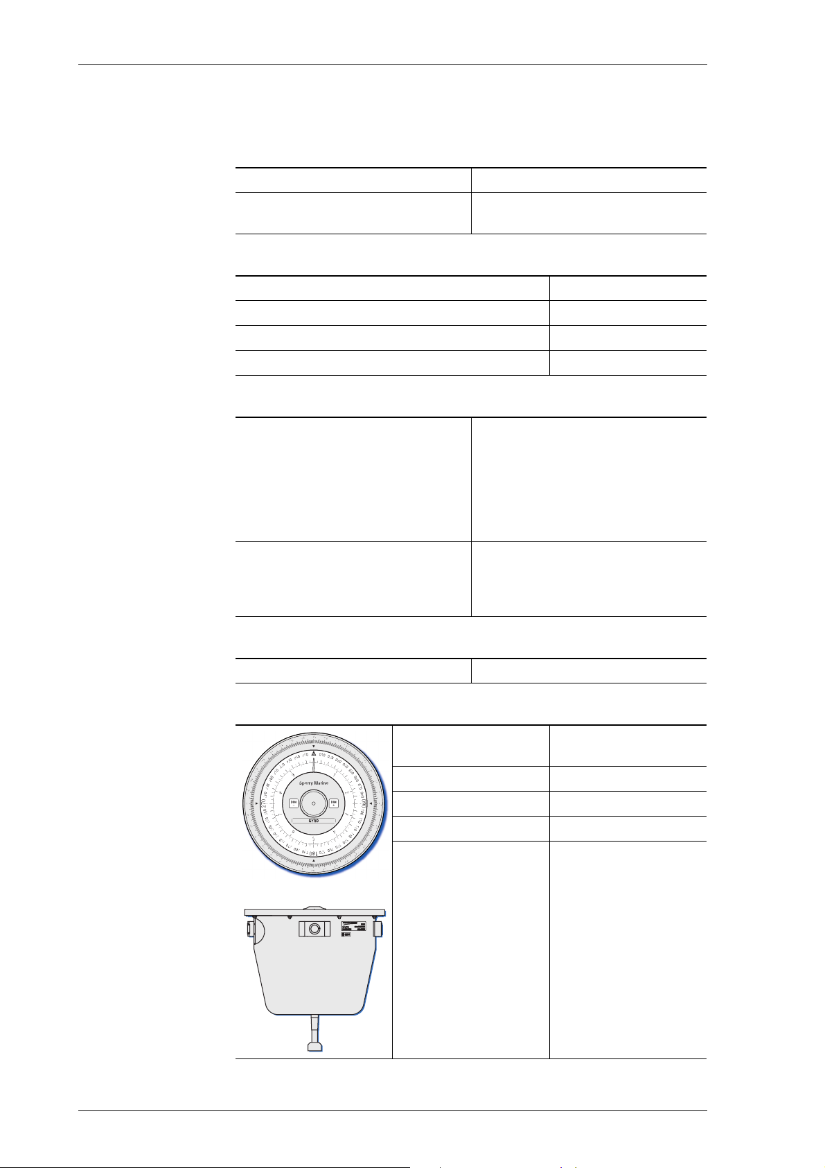
Bearing Repeater, Type 5016-CA
Environmental Requirements
protection grade IP 56 to DIN EN 60529
environmental conditions / EMC
Magnetic Clearance
to standard magnetic compass 0.80 m
to steering magnetic compass 0.50 m
reduced, to standard magnetic compass 0.50 m
reduced, to steering magnetic compass 0.30 m
Readout Elements
360° card diameter
scale graduations
heading scale, numbering
azimuth scale, numbering
10° card diameter
graduation
numbering
verge ring diameter
colour
graduation
numbering
according to IEC 60945, equipment
category “exposed to the weather”
172 mm
outer: every 1°; inner: every 5°
every 10°
every 5°
130 mm
every 0.5°
every 1°
225 mm
white on black
every 1°
every 10°
Controls
Capacitive keys
Dimensions and Weight
diameter at top
(verge ring outer dia.)
height 165 mm
depth 173 mm
weight 5.5 kg
free cable length 2 m
225 mm
1-8 Technical Data
Page 21
Analogue Compass Repeaters 056376/A
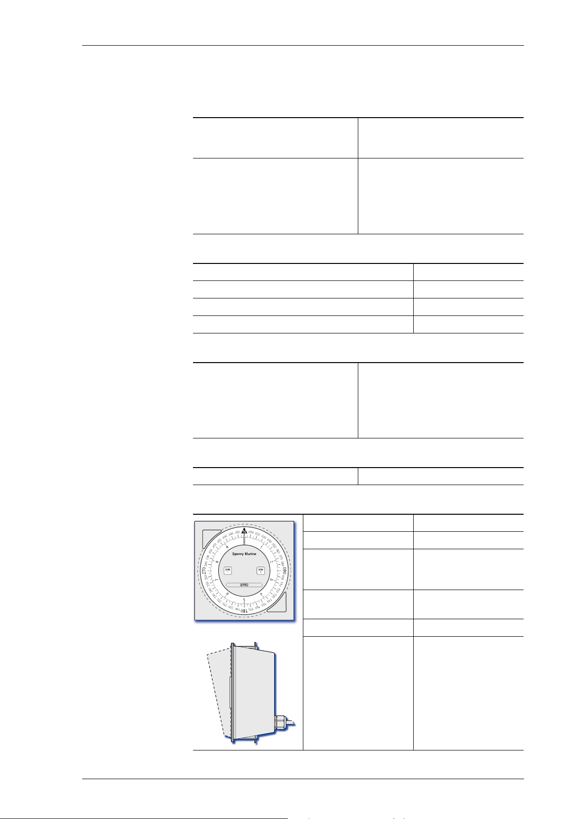
Steering Repeater, Type 5016-CB
Environmental Requirements
protection grade
front side
back
IP 56 to DIN EN 60529
IP 23 to DIN EN 60529
environmental conditions / EMC
installed in console frame
console-mounted, with seal
Magnetic Clearance
to standard magnetic compass 0.75 m
to steering magnetic compass 0.50 m
reduced, to standard magnetic compass 0.45 m
reduced, to steering magnetic compass 0.30 m
Readout Elements
360° card diameter
graduation
numbering
10° card diameter
graduation
numbering
according to IEC 60945,
equipment category “protected
from the weather”
in accordance with IEC 60945,
equipment category “exposed to
the weather”
172 mm
every 5°
every 10°
130 mm
every 0.5°
every 1°
Controls
Push buttons
Dimensions and Weight
width 192 mm
height 192 mm
installation depth
below front plate
projection of sun
shade from front plate
weight 1.25 kg
free cable length 3 m
approx. 125 mm
(including clearance
required for cable)
52 mm
Technical Data 1-9
Page 22
056376/A Analogue Compass Repeaters
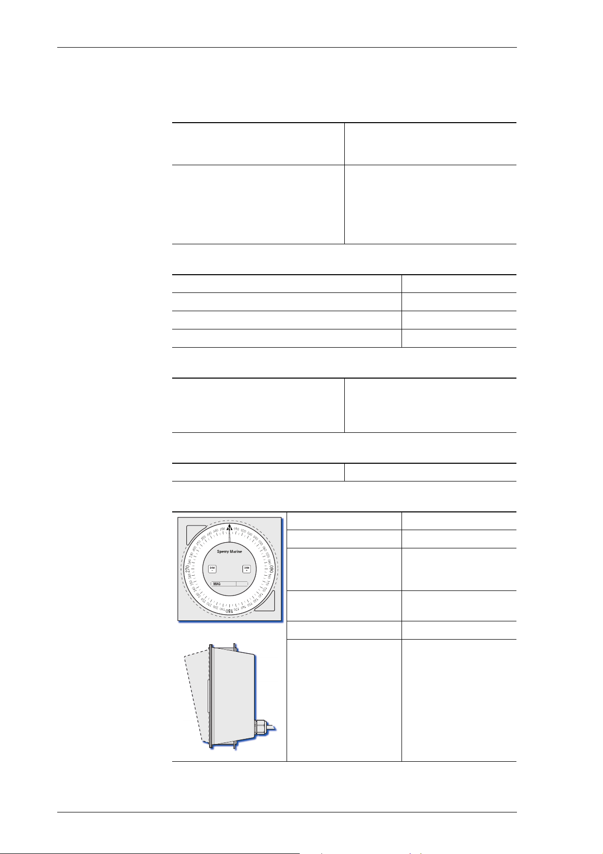
Magnetic Heading Repeater, Type 5016-CC
Environmental Requirements
protection grade
front side
back
IP 56 to DIN EN 60529
IP 23 to DIN EN 60529
environmental conditions / EMC
installed in console frame
console-mounted, with seal
Magnetic Clearance
to standard magnetic compass 0.75 m
to steering magnetic compass 0.50 m
reduced, to standard magnetic compass 0.45 m
reduced, to steering magnetic compass 0.30 m
Readout Elements
360° card
diameter
graduation
numbering
Controls
according to IEC 60945,
equipment category “protected
from the weather”
in accordance with IEC 60945,
equipment category “exposed to
the weather”
172 mm
every 1°
every 10°
Push buttons
Dimensions and Weight
width 192 mm
height 192 mm
installation depth
below front plate
projection of cover
from front plate
weight 1.25 kg
free cable length 3 m
approx. 125 mm
(including clearance
required for cable)
52 mm
1-10 Technical Data
Page 23

Analogue Compass Repeaters 056376/A
Bulkhead Repeater, Type 5016-CD
Environmental Requirements
protection grade IP 56 to DIN EN 60529
environmental conditions / EMC according to IEC 60945, equip-
ment category “exposed to the
weather”
Magnetic Clearance
to standard magnetic compass 0.70 m
to steering magnetic compass 0.40 m
reduced, to standard magnetic compass 0.45 m
reduced, to steering magnetic compass 0.30 m
Readout Elements
360° card
diameter
graduation
numbering
10° card
diameter
graduation
numbering
172 mm
every 5°
every 10°
130 mm
every 0.5°
every 1°
Controls
Push buttons
Dimensions and Weight
width 200 mm
height 240 mm
depth 83 mm
weight 2.5 kg
free cable
length
3 m
Technical Data 1-11
Page 24

056376/A Analogue Compass Repeaters
Bearing Stand, Type 4622
Dimensions and Weight
diameter, top rim 444 mm
height, type 4622-AC
type 4622-AD
weight 10 kg
Bearing Repeater Bracket, Type 4890
Dimensions and Weight
width 462 mm
1450 mm
1300 mm
(including connection
box fitted to right or
left hand side)
depth 390 mm
height 185 mm
weight 5.2 kg
1-12 Technical Data
Page 25
Analogue Compass Repeaters 056376/A
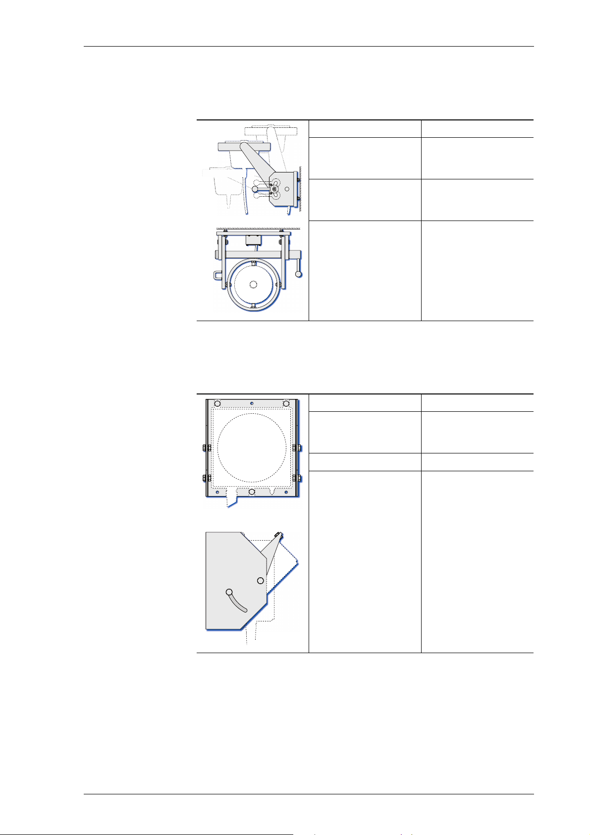
Adjustable Bearing Repeater Bracket, Type 4905
Dimensions and Weight
width 512 mm
depth
lowest position
highest position
height
lowest position
highest position
weight 16.5 kg
560 mm
308 mm
231 mm
481 mm
Bulkhead Repeater Bracket, Stock No. 26857
Dimensions and Weight
width 241 mm
depth 226 mm
(at maximum inclination of repeater)
height 240 mm
weight 3.5 kg
Technical Data 1-13
Page 26
056376/A Analogue Compass Repeaters
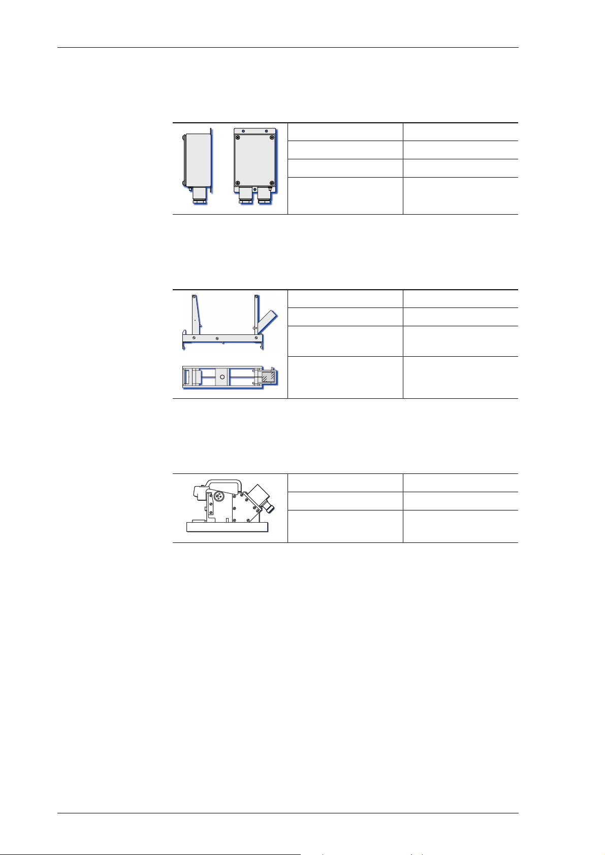
Connection Box, Type 4894-AD
Dimensions and Weight
width 90 mm
depth 60 mm
height 164 mm
weight 0.8 kg
Azimuth Device PV23, Type 2535
Dimensions and Weight
width 62 mm
depth 230 mm
height above repeater top glass
weight 0.6 kg
Telescopic Alidade, Stock no. 60280
Dimensions and Weight
width 236 mm
height 150 mm
weight 3.1 kg
135 mm
1-14 Technical Data
Page 27

Analogue Compass Repeaters 056376/A
Note
1.7 Declaration of Conformity
Marine Equipment Directive EC Declaration of Conformity:
Northrop Grumman Sperry Marine B.V.
Woltmanstrasse 19
D-20097 Hamburg, Germany
as manufacturer hereby declares that the following specified equipment:
“Analogue Compass Repeaters types 5016-CA, -CB, -CC, -CD”
comply with the Marine Equipment Directive 96/98/EC, as amended.
This equipment has been tested to verify compliance with the
Regulations and Testing Standards as per EC Type Examination (B) and
EC Quality System (D) issued by:
Notified Body No. 0098 Germanischer Lloyd.
The current issue of the detailed Marine Equipment Directive EC
Declaration of Conformity of Northrop Grumman Sperry Marine B.V.
Hamburg is part of the client CD stock no. 56 800.
For further details please contact:
Northrop Grumman Sperry Marine B.V. Hamburg
Regulatory Support Group
Declaration of Conformity 1-15
Page 28

056376/A Analogue Compass Repeaters
1-16 Declaration of Conformity
Page 29
Analogue Compass Repeaters 056376/A
2
3
7
8
9
5
4
1
6
Chapter 2: Operation
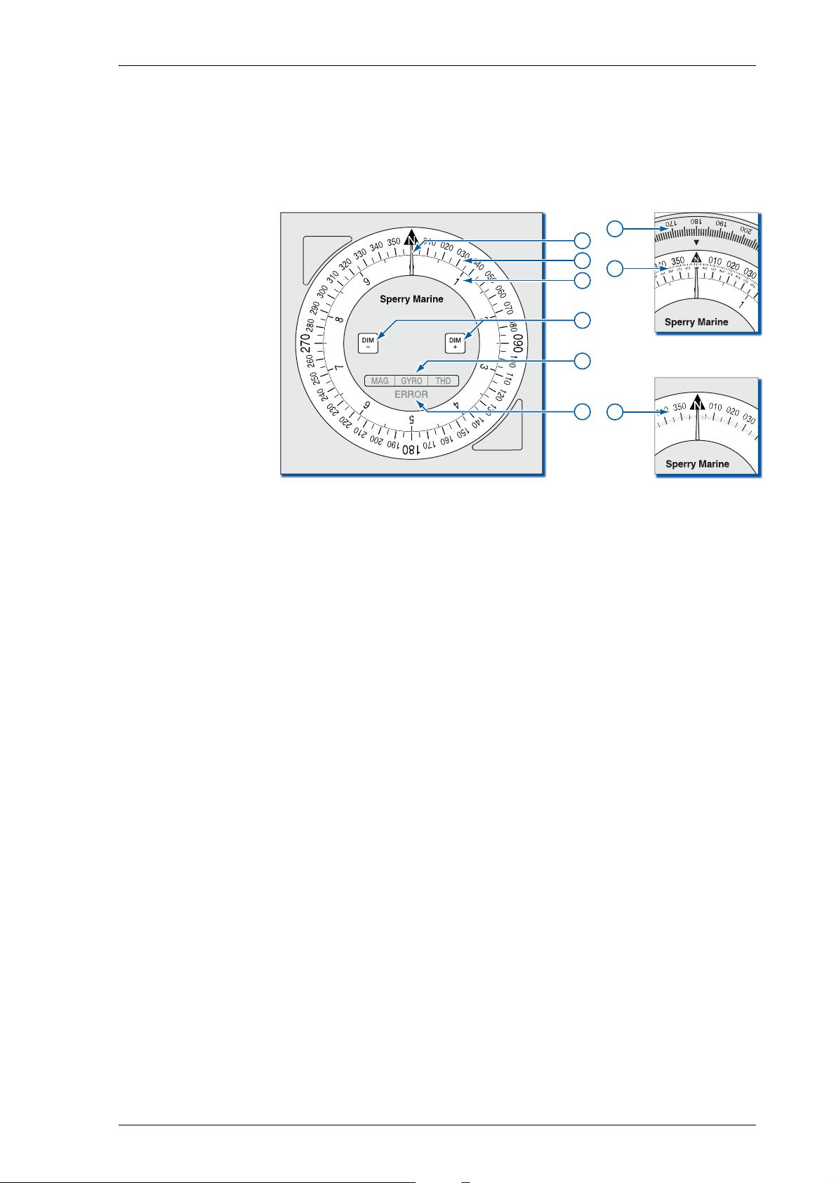
2.1 Readout Elements, Indicators and Controls
Figure 2-1:
Readout elements, indi-
cators and controls
Lubber Line
Indicates the “ahead” direction. Ship’s heading is read off the
compass card(s) at the lubber line.
360° Card
,
Indicates ship’s heading on a 360° (1x) scale. Numbered at 10°,
graduated every 5° (every 1° in magnetic repeater, type 5016-CC).
10° Ca rd
Indicates the “fine” portion of the heading on a 10° (36x) scale.
Numbered every 1°, graduated every 0.5°. Magnetic repeater, type
5016-CC possesses no 10° card.
DIM- / DIM+ keys
Adjust the illumination brightness.
Keep both keys pressed for more than 3 s, then release to initiate
synchronization; keep both keys pressed for more than 10 s, then
release to initiate self test.
Source Indicators
- GYRO = indicating true heading from gyrocompass,
- MAG = indicating magnetic compass heading (raw or corrected),
- THD = indicating true heading from transmitting heading device.
Error indicator
Indicates error conditions visually through blink codes.
Bearing Repeater Verge Ring Scale
Used for taking relative bearings with the azimuth device PV 23.
Bearings read off at the index mark at the “near” side of PV 23.
Bearing Repeater Azimuth Scale
Used for taking absolute bearings with the azimuth device PV 23.
Bearings read off via the mirror prism at the “near” side of PV 23.
Readout Elements, Indicators and Controls 2-1
Page 30

056376/A Analogue Compass Repeaters
Note
Note
2.2 Powering up the Repeaters
The analogue compass repeaters are not equipped with power
switches. The devices power up as soon as supply power is applied.
2.3 Data Protocol and Source Detection
When it is first connected to the gyrocompass system, the repeater
auto-detects the communication parameters by checking for a valid protocol/baudrate combination in the following order:
• NMEA 0183 at 4800 Bd.
• NMEA 0183 at 38400 Bd.
• NMEA 0183 at 9600 Bd.
• NMEA 0183 at 19200 Bd.
• Plath binary format (9600 Bd.)
Once the repeater has recognized valid data, it stores the communication parameters and will re-activate them at subsequent power-ups to
become quickly operative. Should no data be recognized using the
stored communication parameters, the repeater executes the autodetection routine again.
The communication protocol and baudrate may be hard-set in the
repeater configuration. This will disable auto-detection.
Within a standard Sperry Marine NAVIGAT gyrocompass system, the
analogue repeater will receive the heading source selection status from
the compass system.
If the NMEA 0183 protocol is used, the repeater evaluates the proprietary $PPLAN or $PPNSD sentences. If the PLATH protocol is used, the
heading data itself contains a source indicator.
In systems where the NMEA 0183 protocol is used but no $PPLAN or
$PPNSD sentences are received, the repeater determines the active
source by searching the incoming data for valid heading sentences in
the following order of priority:
• $HETHS (source = GYRO)
• any $--THS, except $GPTHS (source = GYRO)
• $HEHDT (source = GYRO)
• any $--HDT, except $GPHDT or $HCHDT (source = GYRO)
• $GPTHS (source = THD)
• $GPHDT (source = THD)
• $HCHDT (source = MAG)
• $HCHDM (source = MAG)
• $HCHDG (source = MAG)
The range of recognized sentences for each source may be restricted by
hard-setting the accepted sentences in the repeater configuration.
Should the currently active heading source get lost, a timeout condition
will occur, the compass card may freeze and the repeater will search the
incoming data for other valid heading sentences in order of priority.
2-2 Powering up the Repeaters
Page 31
Analogue Compass Repeaters 056376/A
WARNING
Only if no valid heading sentences are received at all, the repeater will
raise an error. The error indicator will flash synchronously with one or
all source indicators to indicate that no active heading data are currently
received. The error indication will last until the valid heading data are
again received. For more details see “Error Indication” on page 3-1.
2.4 Reading off Heading and Source Indication
Risk of using invalid heading data
The heading indication at the repeater is only valid if the error indicator
is off and exactly one of the source indicators is permanently lit.
In case the error indicator in on and one or all of the source indicators
are flashing the heading indication of the repeater must be considered
as invalid and the heading data must not be used for steering the vessel.
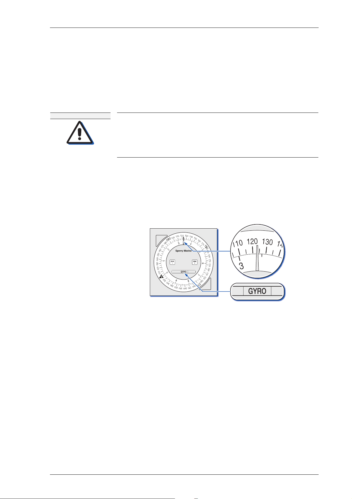
Read the vessel’s heading off the 360° and 10° cards at the lubber line.
The type of heading source in use (gyrocompass = GYRO, magnetic
compass = MAG or transmitting heading device = THD) is indicated
through the corresponding indicator being lit.
As an example, a repeater indicating a gyrocompass heading of 123.4° is
shown below.
For details regarding indication of invalid heading data see
‘Error Indication” on page 3-1.
Reading off Heading and Source Indication 2-3
Page 32
056376/A Analogue Compass Repeaters
Note
2.5 Adjusting the Illumination Brightness
To adjust the backlight and keypad illumination brightness:
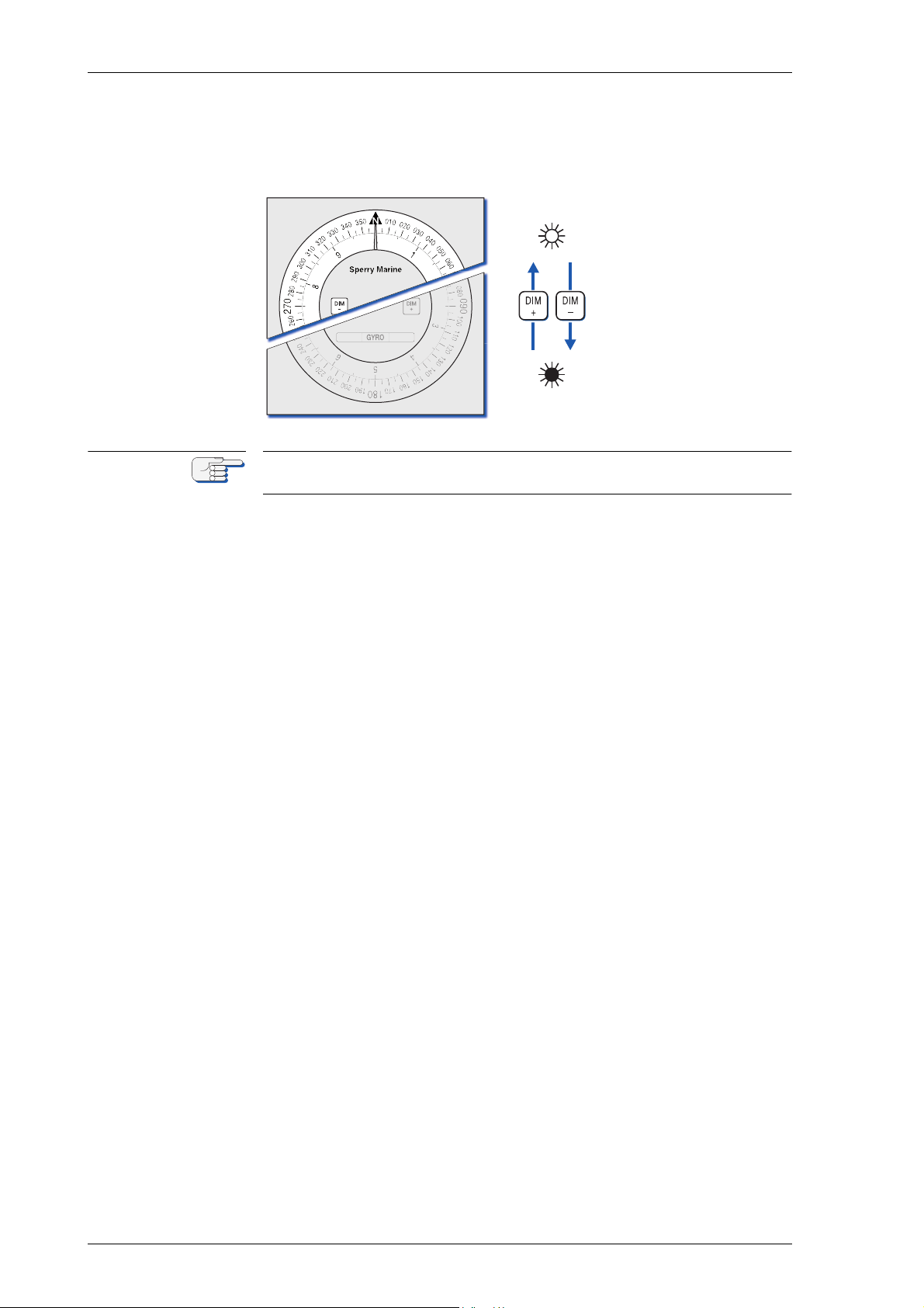
Press DIM+ to
increase the illumination brightness.
Press DIM- to reduce
the illumination
brightness.
Reducing the illumination brightness also reduces the brightness of the
source and error indicator LEDs.
2-4 Adjusting the Illumination Brightness
Page 33

Analogue Compass Repeaters 056376/A
2.6 Synchronizing the Compass Cards
The analogue repeaters are self-synchronizing. They do not normally
require any user intervention to re-synchronize the compass card indication with the actual heading received.
However, the position offset counter may occasionally get out of synchronization with the actual position of the cards, e.g. due to excessive
gear friction at low temperatures or when a repeater is subjected to
heavy shocks during transport.
To initiate compass card synchronization:
1. Press and hold DIM- and DIM+ simultaneously for more than 3 seconds, then release the keys.
2. The compass cards start turning to align to the North (zero degree)
position. When the photo interrupters detect that both cards have
finally aligned, they briefly stop and the position offset is zeroed.
The synchronization is now complete and the repeater automatically
resumes normal operation.
2.7 Initiating the Self Test
To quickly test the proper function of the card drive and the LED indicators, a self test mode is provided.
To initiate the self test:
1. Press and hold DIM- and DIM+ simultaneously for more than 10 seconds. As soon as the active source indicator goes off, release the
keys.
2. The repeater first executes the synchronization routine.
3. Next, all indicators and the backlight come on at maximum brightness for 2 seconds, then go to minimum brightness for 2 seconds
and back to maximum brightness for another 2 seconds.
4. Lastly, the cards turn counterclockwise towards the South position,
stop briefly and then turn clockwise through a full circle until reaching the South position again.
The self test is now complete and the repeater automatically resumes
normal operation.
2.8 Bearing Repeater Capacitive Keys
Although the bearing repeater type 5016-CA is equipped with capacitive
keys, in contrast to the push buttons of the compass repeaters types
5016-CB, -CC and -CD, there is no difference in functionality or handling
neither with adjusting the illumination brightness, synchronizing the
compass cards, nor with initiating the self test.
Synchronizing the Compass Cards 2-5
Page 34
056376/A Analogue Compass Repeaters
WARNING
CAUTION
2.9 Taking Bearings with the Azimuth Device PV 23
Risk of injury
Permanent eye damage may result, when looking directly at the sun or
at its reflection in the black azimuth mirror when using the azimuth
device PV 23.
The PV 23 is not suited for taking the azimuth of the sun itself, as the
coloured shades do not sufficiently block out direct sunlight.
Never look directly at the sun or at its reflection in the black azimuth mirror when using the azimuth device PV 23.
Always engage one or both of the coloured anti-glare filters if necessary
to reduce glare while observing an object
Risk of damage
The prismatic azimuth device PV 23 is not designed to constantly stay on
the bearing repeater compass.
Leaving the azimuth device PV 23 on the bearing repeater after usage,
will cause wear and damage to the equipment.
Always remove the azimuth device PV 23 from the bearing repeater and
store it carefully in its storage box.
1. Mount the azimuth device PV 23 onto the bearing repeater:
a) Holding the PV 23 slightly tilted to the far side, hook the far side
catch under the rim of the repeater’s verge ring.
b) Let the centering pin at the underside of the PV 23 engage into
the recess of the repeater faceplate.
c) Push down on the near side of the PV 23.
The flexible near side catch snaps into place and the PV 23 is free
to rotate around the centering pin.
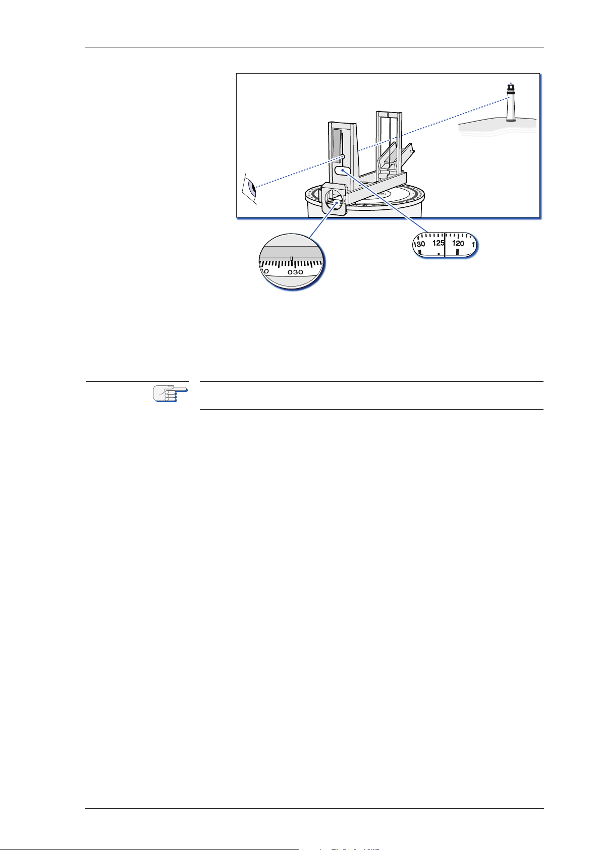
2. Take bearings:
a) Peep through the near sight while rotating the PV 23 towards the
object to observe.
b) If necessary, engage one or both of the coloured shades to
reduce glare while observing the object.
c) Continue to rotate the PV 23 until both sights are aligned with the
observed object.
If the object’s elevation is too high for direct observation, pick up
the object’s reflection in the black azimuth mirror and align the
sights with the reflection.
2-6 Taking Bearings with the Azimuth Device PV 23
Page 35
Analogue Compass Repeaters 056376/A
absolute
bearing
relative
bearing
Note
3. Read bearings:
a) Read the object’s absolute bearing off the azimuth scale through
the prism below the near sight.
b) Read the object’s relative bearing off the verge ring scale at the
index mark on the PV 23.
Have in mind that, being read from the near side, the azimuth and verge
ring scales run from right to left.
Taking Bearings with the Azimuth Device PV 23 2-7
Page 36

056376/A Analogue Compass Repeaters
2-8 Taking Bearings with the Azimuth Device PV 23
Page 37
Analogue Compass Repeaters 056376/A
Note
Chapter 3: Error Indication
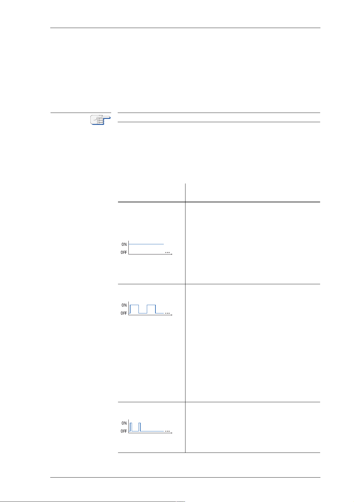
When a repeater compass detects an error, the red error indicator
flashes or lights up permanently depending on error condition.
The error indication remains active until the cause of the error is eliminated or no longer persists.
The repeater compasses do not possess an audible alarm indicator.
3.1 Error Blink Codes
When an error is detected, the error condition at hand is indicated by the
error indicator showing a corresponding blink code.
Table 3-1:
Repeater compass
error blink codes
error condition/ blink
code
no activity at data input
or
power-up failure
permanently on
heading timeout
on / off for equal periods
corrective action
Check whether data are present at source’s
output.
Check connection between source and repeater.
Check whether the repeater reacts to key
presses (dimming, synchronization). If keys
are not functional, the repeater did not enter
normal operational mode.
Cycle power.
If the error persists, send the repeater back to
Sperry Marine for exchange.
Check whether source provides valid heading
data.
In NAVIGAT compass systems, check that
heading data originates from selected source
according to $PPLAN/$PPNSD sentence.
Check source’s protocol and baudrate settings.
Check whether repeater configuration is hardset to different parameters than source’s output.
In case one or all source indicators are flashing together with the error indicator see
“Heading Timeout with flashing Source Indicator” on page 3-2 for additional information
and corrective action.
If the error persists, send the repeater back to
Sperry Marine for exchange.
synchronization fault
two short flashes followed by a pause
Error Blink Codes 3-1
Initiate synchronization of the compass cards.
Cycle power.
If the error persists after several attempts to
synchronize, return the repeater to Sperry Marine for exchange.
Page 38

056376/A Analogue Compass Repeaters
Heading Timeout with flashing Source Indicator
In case of a heading timeout, one or all of the source indicators may
flash in synchronously with the error indicator. This provides additional
information regarding the cause of the timeout.
• If one of the source indicator flashes, no heading data is received
from the currently active source. Possible causes:
– The active source selection is read from the proprietary $PPLAN
or $PPNSD sentences but no valid heading is received from the
selected source.
– The active source has marked its heading data invalid or has
stopped sending data and no valid heading data is received from
another source.
• If all source indicators flash simultaneously, valid datagrams are recognized at the input but the currently active source cannot be determined. Possible causes:
– NMEA sentences are received but these do not contain any of the
recognized heading sentences.
– NMEA heading sentences are recognized but are excluded from
the range of accepted sentences in the repeater’s configuration.
3-2 Error Blink Codes
Page 39

Analogue Compass Repeaters 056376/A
CAUTION
Chapter 4: Preventive Maintenance
4.1 Maintenance by Shipboard Personnel
Risk of damage through wrong cleaning agent
The front plates of the compass repeaters are sensitive against aggressive cleaning agents as organic solvents or acetone.
Do not clean the front plate with organic solvents, acetone or any other
aggressive cleaning agent.
Use only water and soap or a mild detergent to clean the front plate.
The analogue compass repeaters are maintenance-free. All internal
moving parts, such as the stepper motor, gear train and bearings, are
lifetime-lubricated. The gimbals of the bearing stand and bearing consoles are fitted with self-lubricating polymer bushings.
Shipboard personnel is only requested to keep the compass repeaters
clean and to regularly check all cables and connectors visually for any
signs of damage or deterioration.
All compass repeater front plates should regularly become cleaned
using water and soap or a mild detergent only.
Maintenance by Shipboard Personnel 4-1
Page 40
056376-A Analogue Compass Repeaters
CAUTION
CAUTION
CAUTION
Maintenance of externally installed Bearing Repeater
Risk of damage though solar radiation
The bearing repeater 5016-CA is equipped with a cover plate for protection against solar radiation.
It is recommended to always protect the bearing repeater with the cover
plate when not in use.
Risk of damage
The cover plate, protecting the bearing repeater 5016-CA against solar
radiation, must never be touched with tools to avoid any damage.
Always install and remove the cover plate with bare hands only.
Risk of unnecessary wear
The bearing repeater 5016-CA can optionally be equipped with a watertight plastic cover for protection against environmental conditions.
It is recommended to always protect the bearing repeater with the plastic
cover when not in use.
Of course, depending on whether the compass repeater is installed
externally or internally, the cleaning effort may vary and will be
increased with exposition to environmental conditions, e.g. when
installed on the fly bridge or top desk.
Especially the bearing repeater installed on a bearing stand is permanently exposed to environmental conditions and does therefore need
additional protection for long time usage and for reduction of unnecessary wear.
It is therefore recommended to always protect the bearing repeater with
the cover plate against solar radiation when not in use.
Additionally, the usage of the watertight plastic cover for protection
against all environmental conditions is also recommended when the
bearing repeater is not in use.
4-2 Maintenance by Shipboard Personnel
Page 41
Analogue Compass Repeaters 056376/A
CAUTION
CAUTION
Note
Chapter 5: Installation
5.1 Bearing Repeater
Installing Bearing Repeater with Bearing Stand
Risk of wrong installation
Wrong positioning of the bearing stand will obstruct to take bearings.
Always make sure that the bearing stand is so positioned that the vessel’s superstructure does not unduly obstruct the view of the horizon.
In case one bearing stand does not allow to take bearings in a full circle
of 360°, a second bearing stand must be installed for compensation.
Risk of damage
The bearing repeater is a heavy instrument.
To avoid any damage during installation of the bearing repeater into the
gimbal ring, the installation should be carried out by two service persons.
Bearing repeater stands may be positioned amidships (on the fore-andaft line) or at the port or starboard sides of the vessel. The position of
the bearing stand(s) is to be chosen that the vessel’s superstructure
does not unduly obstruct the view of the horizon when bearings are
taken. In case one bearing stand does not allow take bearings in a full
circle of 360°, a second bearing stand must be installed for compensation.
The bearing stand, type 4622, is to be attached to the deck or a pedestal
using four M 20 fasteners. Tubular spacers are provided, which are to be
inserted between the mounting surface and the base of the stand. The
four attachment points are to be located on an imaginary circle of
370 mm diameter, at the 0°, 90°, 180° and 270° positions relative to the
forward direction. The elongated holes in the base of the bearing stand
allow to correct a misalignment of ±3.5° max.
A cable feedthrough is to be located centrally beneath the stand, so that
the connection cable from the compass system runs up the inside of the
stand column.
The installation of the repeater in the gimbal ring should be carried out
by two service persons.
To install the bearing stand and bearing repeater:
1. Check that the mounting facilities and the cable feedthrough provided by the shipyard match with the specifications given in dimension drawing 4622-0112-03 respectively 4622-0112-06.
2. Lay the connecting cable. Make sure that enough cable exits from
the feedthrough to run it up the stand column and through the
grommet to the connection box.
Bearing Repeater 5-1
Page 42

056376/A Analogue Compass Repeaters
Note
3. If the mounting surface is furnished with tapped holes, place the
tubular spacers over the holes. If welded studs are provided, slide
the spacers onto the studs.
4. Place the bearing stand on top of the spacers. The stand may be
mounted in any of the four possible orientations. Make sure, however, that the connection box is easily accessible.
5. Loosely attach the bearing stand to the mounting surface with the
fasteners provided by the shipyard. Use washers. Do not yet tighten
the fasteners.
6. Remove the grommet from the cable exit in the stand column.
7. Run the connection cable up the stand column and through the exit
to the outside of the stand.
8. Loosen one of the lock nuts securing the trunnions in the gimbal ring
and screw back the trunnion by approximately 2 cm.
9. Hold the repeater in a convenient position close to the bearing stand.
Unwind the repeater connection cable and run it through the gimbal
ring, the stand column and the cable exit to the outside of the stand.
10. Lift the bearing repeater into the gimbal ring so that the lubber line
points in the forward direction.
11. Locate the fixed trunnion in the bushing in the repeater.
12. Turn the loosened trunnion clockwise into the opposite bushing, so
that the repeater is secured without play in the gimbal ring.
Make sure that the repeater swings freely in the gimbal ring without
jamming.
13. Check that the repeater is centered in the gimbal ring. If necessary,
adjust the trunnions to center the repeater.
14. Carefully tighten the trunnion lock nuts until they are just free of
clearance.
15. Align the bearing stand with the vessel’s fore-and-aft line as follows:
a) Determine the exact lateral distance between the stand’s centre
and the vessel’s fore-and-aft line.
b) Position a beam with a perpendicular reference mark well for-
ward of the bearing stand, at the same lateral distance from the
fore-and-aft line.
c) Fit a PV 23 azimuth device to the bearing repeater.
d) Take a bearing of the reference mark on the beam.
The bearing is to be 360° exactly. If necessary, gently rotate the
bearing stand until a bearing of 360° is obtained.
e) Position a second beam well aft of the bearing stand.
f) Take a bearing of the reference mark on the beam.
Check that the bearing is 180° exactly. If necessary, correct any
misalignment by rotating the bearing stand, then re-check the
bearings of the two beams.
In case the bearing stand is mounted amidships (on the fore-and-aft line),
no beams need to be erected if bearings can be taken of objects on the
fore-and-aft line, e.g. the centre of the foremast, flagstaff etc.
16. Tighten the fasteners on the repeater stand base.
5-2 Bearing Repeater
Page 43

Analogue Compass Repeaters 056376/A
17. Punch or cut a hole for the connection cables into the grommet, slide
the grommet onto the cables and press it into the cable exit.
18. Remove the cover plate from the connection box.
19. Remove the cable jacket from the ends of the connection cables,
draw back the cable screens and insert the cables into the connection box through the cable glands.
20. Firmly tighten the cable glands. Make sure to establish a solid connection between the screens and ship’s ground via the glands.
21. Connect the repeater and shipside wires to the terminal blocks as
per the wiring diagrams and connection drawings provided.
22. In case a custom configuration is required, configure the repeater
now using the SUSI application (see chapter 6, ‘Configuration”).
23. Attach the cover plate to the connection box, power up the compass
system and carry out a full functional test of the repeater.
Bearing Repeater 5-3
Page 44
056376/A Analogue Compass Repeaters
CAUTION
CAUTION
Note
Installing Bearing Repeater with Bearing Bracket
Risk of wrong installation
Wrong positioning of the bearing stand will obstruct to take bearings.
Always make sure that the bearing stand is so positioned that the vessel’s superstructure does not unduly obstruct the view of the horizon.
In case one bearing stand does not allow to take bearings in a full circle
of 360°, a second bearing stand must be installed for compensation.
Risk of damage
The bearing repeater is a heavy instrument.
To avoid any damage during installation of the bearing repeater into the
gimbal ring, the installation should be carried out by two service persons.
The bearing repeater bracket, type 4890, is typically fitted to a bulwark
or other vertical surface parallel or perpendicular to the vessel’s foreand-aft line. The position of the bearing bracket(s) is to be chosen that
the vessel’s superstructure does not unduly obstruct the view of the
horizon when bearings are taken. In case one bearing bracket does not
allow take bearings in a full circle of 360°, a second bearing bracket must
be installed for compensation.
The shipyard is to provide the mounting surface with four M 10 bolts or
welded studs, to which the bracket is then attached with nuts and washers. The mounting surface should be as exactly parallel or perpendicular
to the fore-and-aft line as possible, as the mounting method permits to
correct only a small amount of misalignment.
The installation of the repeater in the gimbal ring should be carried out
by two service persons.
To install the bearing repeater bracket and repeater:
1. Check that the mounting facilities provided by the shipyard match
with the specifications given in dimension drawing 4890-0112-03.
2. Check that easy access is provided to the connection box at the right
hand side of the bracket. If necessary, unmount the box and fit it to
the bracket’s left hand side or directly onto the bulwark.
3. Screw a thin M 10 nut onto each of the four mounting studs.
Leave a few threads exposed between the nuts and the mounting
surface to allow for fine-adjustment of the nuts’ positions later
4. Put a flat washer onto each nut.
5. Fasten the bearing repeater bracket to the attachment studs with
four thin nuts and washers. Tighten the nuts only lightly.
6. Loosen one of the lock nuts securing the trunnions in the gimbal ring
and screw back the trunnion by approximately 2 cm.
7. Hold the repeater in a convenient position close to the bracket.
Unwind the repeater connection cable and run it through the gimbal
ring from above.
8. Lift the bearing repeater into the gimbal ring so that the lubber line
points in the forward direction.
5-4 Bearing Repeater
Page 45

Analogue Compass Repeaters 056376/A
Note
9. Locate the fixed trunnion in the bushing in the repeater.
10. Turn the loosened trunnion clockwise into the opposite bushing, so
that the repeater is secured without play in the gimbal ring.
Make sure that the repeater swings freely in the gimbal ring without
jamming.
11. Check that the repeater is centered in the gimbal ring. If necessary,
adjust the trunnions to center the repeater.
12. Carefully tighten the trunnion lock nuts until they are just free of
clearance.
13. Align the bearing repeater bracket with the vessel’s fore-and-aft line
as follows:
a) Determine the exact lateral distance between the bracket’s centre
and the vessel’s fore-and-aft line.
b) Position a beam with a perpendicular reference mark well for-
ward of the bearing stand, at the same lateral distance from the
fore-and-aft line.
c) Fit a PV 23 azimuth device to the bearing repeater.
d) Take a bearing of the reference mark on the beam.
The bearing is to be 360° exactly. If necessary, fine-adjust the
positions of the flat nuts on the attachment studs until a bearing
of 360° is obtained.
e) Position a second beam well aft of the bearing stand.
f) Take a bearing of the reference mark on the beam.
Check that the bearing is 180° exactly. If necessary, correct any
misalignment by readjusting the flat nuts, then re-check the bearings of the two beams.
In case the bearing repeater bracket is mounted amidships (on the foreand-aft line), no beams need to be erected if bearings can be taken of
objects on the fore-and-aft line instead, e.g. the centre of the foremast,
flagstaff etc.
14. Thoroughly tighten the flat nuts on the attachment studs.
15. Remove the cover plate from the connection box.
16. Shorten the repeater and shipside connection cables as required.
17. Remove the cable jacket from the ends of the connection cables,
draw back the cable screens and insert the cables into the connection box through the cable glands.
18. Firmly tighten the cable glands. Make sure to establish a solid connection between the screens and ship’s ground via the glands.
19. Connect the repeater and shipside wires to the terminal blocks as
per the wiring diagrams and connection drawings provided.
20. In case a custom configuration is required, configure the repeater
now using the SUSI application (see chapter 6, ‘Configuration”).
21. Attach the cover plate to the connection box, power up the compass
system and carry out a full functional test of the repeater.
Bearing Repeater 5-5
Page 46
056376/A Analogue Compass Repeaters
CAUTION
CAUTION
Note
Installing Bearing Repeater with Adjustable Bearing Bracket
Risk of wrong installation
Wrong positioning of the bearing stand will obstruct to take bearings.
Always make sure that the bearing stand is so positioned that the vessel’s superstructure does not unduly obstruct the view of the horizon.
In case one bearing stand does not allow to take bearings in a full circle
of 360°, a second bearing stand must be installed for compensation.
Risk of damage
The bearing repeater is a heavy instrument.
To avoid any damage during installation of the bearing repeater into the
gimbal ring, the installation should be carried out by two service persons.
The adjustable bearing repeater bracket 4905 is typically fitted to a bulwark or other vertical surface parallel or perpendicular to the vessel’s
fore-and-aft line. The position of the adjustable bearing bracket(s) is to
be chosen that the vessel’s superstructure does not unduly obstruct the
view of the horizon when bearings are taken. In case one bearing
bracket does not allow take bearings in a full circle of 360°, a second
adjustable bearing bracket must be installed for compensation.
The shipyard is to provide the mounting surface with four M 10 bolts or
welded studs, to which the bracket is then attached with nuts and spherical washers with conical seats. The mounting surface should be as
exactly parallel or perpendicular to the fore-and-aft line as possible. The
mounting method permits to correct a misalignment of ±3.0° max.
The installation of the repeater in the gimbal ring should be carried out
by two service persons.
To install the adjustable bearing bracket and bearing repeater:
1. Check that the mounting facilities provided by the shipyard match
with the specifications given in dimension drawing 4905-0112-03.
2. Screw a thin M 10 nut onto each of the four mounting studs.
Leave a few threads exposed between the nuts and the mounting
surface to allow for fine-adjustment of the nuts’ positions later.
3. Put a spherical washers with conical seat onto each of the nuts.
4. Fasten the adjustable bearing repeater bracket to the attachment
studs with four thin nuts and spherical washers with conical seats.
Tighten the nuts only lightly.
5. Loosen one of the lock nuts securing the trunnions in the gimbal ring
and screw back the trunnion by approximately 2 cm.
6. Hold the repeater in a convenient position close to the bracket.
Unwind the repeater connection cable and run it through the gimbal
ring from above.
7. Lift the bearing repeater into the gimbal ring so that the lubber line
points in the forward direction.
8. Locate the fixed trunnion in the bushing in the repeater.
5-6 Bearing Repeater
Page 47

Analogue Compass Repeaters 056376/A
Note
9. Turn the loosened trunnion clockwise into the opposite bushing, so
that the repeater is secured without play in the gimbal ring.
Make sure that the repeater swings freely in the gimbal ring without
jamming.
10. Check that the repeater is centered in the gimbal ring. If necessary,
adjust the trunnions to center the repeater.
11. Carefully tighten the trunnion lock nuts until they are just free of
clearance.
12. Align the bearing repeater bracket with the vessel’s fore-and-aft line
as follows:
a) Determine the exact lateral distance between the bracket’s centre
and the vessel’s fore-and-aft line.
b) Position a beam with a perpendicular reference mark well for-
ward of the bearing stand, at the same lateral distance from the
fore-and-aft line.
c) Fit a PV 23 azimuth device to the bearing repeater.
d) Take a bearing of the reference mark on the beam.
The bearing is to be 360° exactly. If necessary, adjust the positions of the flat nuts on the attachment studs until a bearing of
360° is obtained.
e) Position a second beam well aft of the bearing stand.
f) Take a bearing of the reference mark on the beam.
Check that the bearing is 180° exactly. If necessary, correct any
misalignment by readjusting the flat nuts, then re-check the bearings of the two beams.
In case the bearing repeater bracket is mounted amidships (on the foreand-aft line), no beams need to be erected if bearings can be taken of
objects on the fore-and-aft line instead, e.g. the centre of the foremast,
flagstaff etc.
13. Thoroughly tighten the flat nuts on the attachment studs.
14. Remove the cover plate from the connection box.
15. Shorten the repeater and shipside connection cables as required.
16. Remove the cable jacket from the ends of the connection cables,
draw back the cable screens and insert the cables into the connection box through the cable glands.
17. Firmly tighten the cable glands. Make sure to establish a solid connection between the screens and ship’s ground via the glands.
18. Connect the repeater and shipside wires to the terminal blocks as
per the wiring diagrams and connection drawings provided.
19. In case a custom configuration is required, configure the repeater
now using the SUSI application (see chapter 6, ‘Configuration”).
20. Attach the cover plate to the connection box, power up the compass
system and carry out a full functional test of the repeater.
Bearing Repeater 5-7
Page 48

056376/A Analogue Compass Repeaters
CAUTION
5.2 Steering Repeater / Magnetic Heading Repeater
Risk of damage
The compass repeaters are heavy instruments. The compass repeater
cables are not designed for holding the repeater just with the cable.
Never hold or transport the repeater on the cable alone when installing
or wearing a compass repeater.
The steering repeater, type 5016-CB, and the magnetic heading repeater,
type 5016-CC; are supplied with four attachment columns and mounting
clamps for installation in a standard Sperry Marine console frame or
directly into a console cutout.
In case of direct console mounting, the shipyard is to cut a square opening into the console as per dimension drawing 5016-0112-02.
To install the repeater in a console frame:
1. Loosen the four screws on the attachment columns and rotate the
mounting clamps inward.
2. Connect the repeater cable to the shipside terminals as per the wiring diagrams and connection drawings provided.
3. Install a ground strap between the ground tab at the back of the
repeater housing and ship’s ground.
4. In case a custom configuration is required, configure the repeater
now using the SUSI application (see chapter 6, ‘Configuration”).
5. Insert the repeater into the frame.
6. Rotate the mounting clamps outward and fasten them with the
retaining screws.
7. Power up the compass system and carry out a full functional test of
the repeater.
5-8 Steering Repeater / Magnetic Heading Repeater
Page 49

Analogue Compass Repeaters 056376/A
To install the repeater directly in a console cutout:
1. Remove the four screws, clamps and washers from the attachment
columns. This exposes four M 4 studs on the back of the repeater’s
front plate.
2. Fit a clamp and washer onto each of the studs, rotate it inward and
lightly fasten it with an attachment column.
3. If watertight installation is required, fit the provided rubber seal to
the back of the repeater.
4. Connect the repeater cable to the shipside terminals as per the wiring diagrams and connection drawings provided.
5. Install a ground strap between the ground tab at the back of the
repeater housing and ship’s ground.
6. In case a custom configuration is required, configure the repeater
now using the SUSI application (see chapter 6, ‘Configuration”).
7. Insert the repeater in the console cutout.
8. Rotate the mounting clamps outward and thoroughly fasten them
with the attachment columns.
9. Power up the compass system and carry out a full functional test of
the repeater.
Steering Repeater / Magnetic Heading Repeater 5-9
Page 50

056376/A Analogue Compass Repeaters
CAUTION
CAUTION
5.3 Bulkhead Repeater
Risk of damage
The compass repeaters are heavy instruments. The compass repeater
cables are not designed for holding the repeater just with the cable.
Never hold or transport the repeater on the cable alone when installing
or wearing a compass repeater.
Risk of malfunction
Do not lengthen the cable between the bulkhead repeater and the connection box as the USB service port will not work reliably.
If the connection box cannot be installed at an accessible location close
to the repeater, it will be required to unmount and disassemble the
repeater to gain access to the internal USB receptacle when configuring
or servicing the device.
If the repeater cable is connected directly to shipside terminals, the external USB port may not be used and its four wires must be connected to
blind terminals.
The bulkhead repeater, type 5016-CD, is attached directly onto a bulkhead or is fitted to the optional swivelling mounting bracket. For this
purpose, the bulkhead repeater housing possesses three attachment
feet with 7 mm holes.
In case of direct bulkhead mounting, the shipyard is to provide the
mounting surface with three M 6 weld studs or tapped holes, to which
the repeater is attached. In case the optional swivelling bracket is used,
the shipyard is to provide the mounting surface with four M 8 weld
studs or tapped holes, to which the bracket is attached.
The bulkhead repeater’s electrical connection is normally made via the
connection box 4894-AD. As the box contains the service USB port, it
should be installed at an easily accessible location close to the repeater.
To install the bulkhead repeater:
1. If the repeater is to be mounted directly onto a bulkhead:
a) Check that the mounting facilities provided by the shipyard
match with the specifications given in dimension drawing
5016-0112-03
b) Fasten the repeater to the bulkhead with suitable fasteners (ship-
yard supply).
If the swivelling bracket is used:
c) Check that the mounting facilities provided by the shipyard
match with the specifications given in dimension drawing
5016-0112-04
d) Fasten the bracket or the to the bulkhead with suitable fasteners
(shipyard supply).
e) Fasten the repeater to the bracket with the fasteners provided.
2. Install a ground strap between the ground stud at the bottom of the
repeater housing and ship’s ground.
5-10 Bulkhead Repeater
Page 51

Analogue Compass Repeaters 056376/A
3. Install the connection box at an easily accessible location close to
the repeater.
4. Remove the cover plate from the box.
5. Shorten the repeater and shipside connection cables as required.
6. Remove the cable jacket from the ends of the connection cables,
draw back the cable screens and insert the cables into the connection box through the cable glands.
7. Firmly tighten the cable glands. Make sure to establish a solid connection between the screens and ship’s ground via the glands.
8. Connect the repeater and shipside wires to the terminal blocks as
per the wiring diagrams and connection drawings provided.
9. In case a custom configuration is required, configure the repeater
now using the SUSI application (see chapter 6, ‘Configuration”).
10. Attach the cover plate to the connection box, power up the compass
system and carry out a full functional test of the repeater.
Bulkhead Repeater 5-11
Page 52

056376/A Analogue Compass Repeaters
5-12 Bulkhead Repeater
Page 53

Analogue Compass Repeaters 056376/A
Note
Chapter 6: Configuration
6.1 Using the Default Configuration
The repeater’s factory default configuration will be suitable for most
installations and will normally not require any customization.
By default, the repeater configuration is “all-automatic”, permitting autodetection of the input protocol and baudrate as well as the active heading source.
The automatic source detection takes place as described in chapter 2,
section 2.3, “Data Protocol and Source Detection”.
The magnetic heading repeater is configured by default to display magnetic heading only, regardless of which source is currently active.
6.2 Configuring the Analogue Repeater with SUSI
This section is intended for authorized service personnel configuring or
servicing an analogue repeater. These tasks require a PC running the
Sperry Universal Service Instrument (SUSI) application. SUSI is provided
to authorized service personnel only and is generally not available to
end-customers.
Should it be required to configure the repeater using other settings than
the factory defaults, the configuration settings must be accessed from a
PC (field engineer’s laptop or notebook computer) connected to the
repeater’s USB service port and running the Sperry Universal Service
Instrument application (SUSI).
For the present section, it is assumed that you have successfully
installed SUSI and the USB device driver for the analogue repeaters on
your PC. Once an analogue repeater is connected to the PC, a device
named “RCS - NGSM Service USB Port” (repeater compass system)
must appear in the Windows Device Manager, listed as a modem
device.
If you have not yet installed the SUSI and/or the device driver, refer to
the SUSI Installation Guide, included in the Sperry Marine Client-CD
056800. Support for the analogue repeater is available in SUSI versions
1.024 and higher. If you are using an earlier version, obtain the current
SUSI installation package from Sperry Marine and re-install the software.
The procedures described below are performed using the controls
appearing in SUSI’s application tab when connecting to the repeater.
More advanced configuration features, accessible through SUSI’s terminal and parameter tabs, are beyond the scope of this manual.
If configuring a repeater using other settings than the factory defaults,
note all settings in the analogue compass repeater setup table (see
Appendix). Send a copy of the filled-out table to Sperry Marine for inclusion in the ship’s file.
Using the Default Configuration 6-1
Page 54
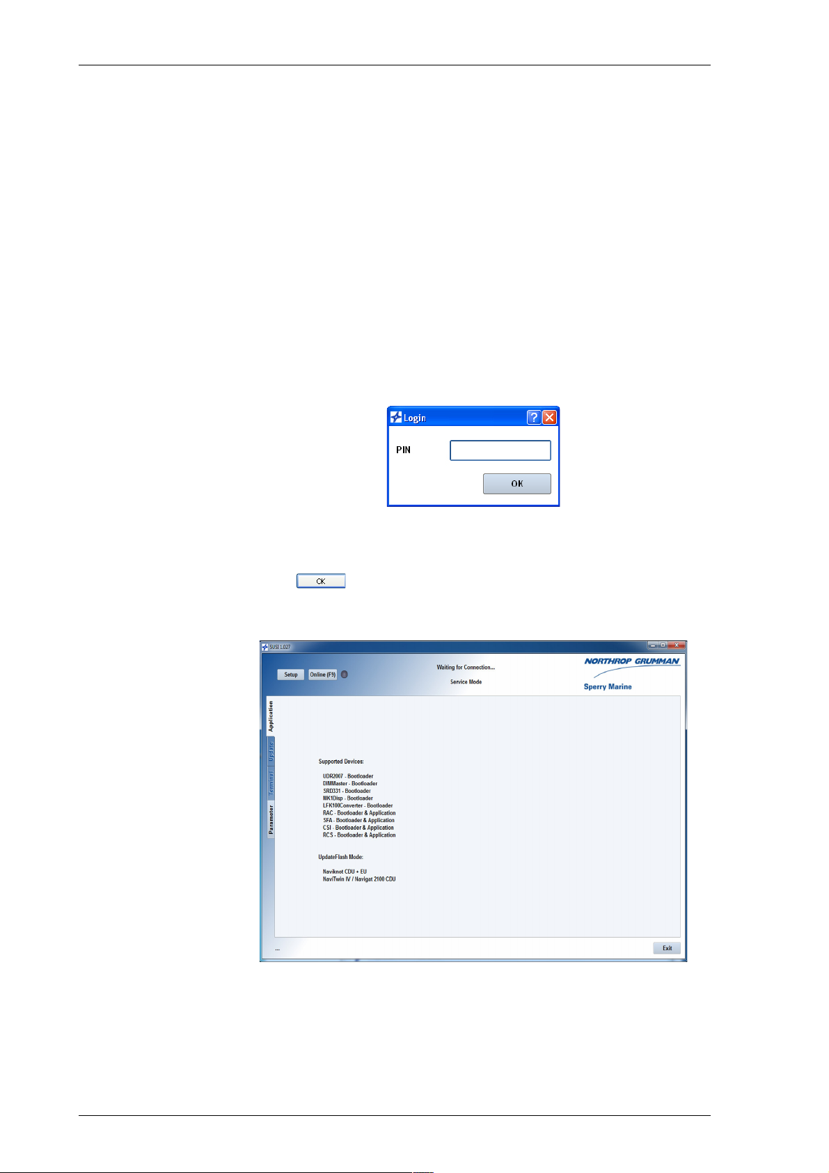
056376/A Analogue Compass Repeaters
To configure the analogue repeater:
1. If the repeater is currently powered up, switch off the power first.
2. Gain access to the repeaters USB service port receptacle:
– In case of a steering or magnetic heading repeater, remove the
plastic plug from the back of the housing to access the receptacle
on the repeater PCB. If necessary, unmount the repeater from the
console to make sure that the port is freely accessible for plugging and unplugging the USB cable.
– In case of a bearing or bulkhead repeater, remove the cover plate
from the connection box to access the receptacle inside the box.
Do not plug in the USB cable yet.
3. Power up the repeater.
4. At the PC, start up the SUSI application.
A login dialogue pops up:
5. Enter PIN “20097”.
This will start up SUSI in the service mode.
Click or the enter key to continue.
6. SUSI’s main window now opens, with the “Application” tab displaying a list of supported devices:
7. The “Online” button at the top left of SUSI’s main window will be
greyed out, as SUSI has not yet detected a device to connect to.
The status line at the top center of the window will read “Waiting for
Connection...”.
6-2 Configuring the Analogue Repeater with SUSI
Page 55
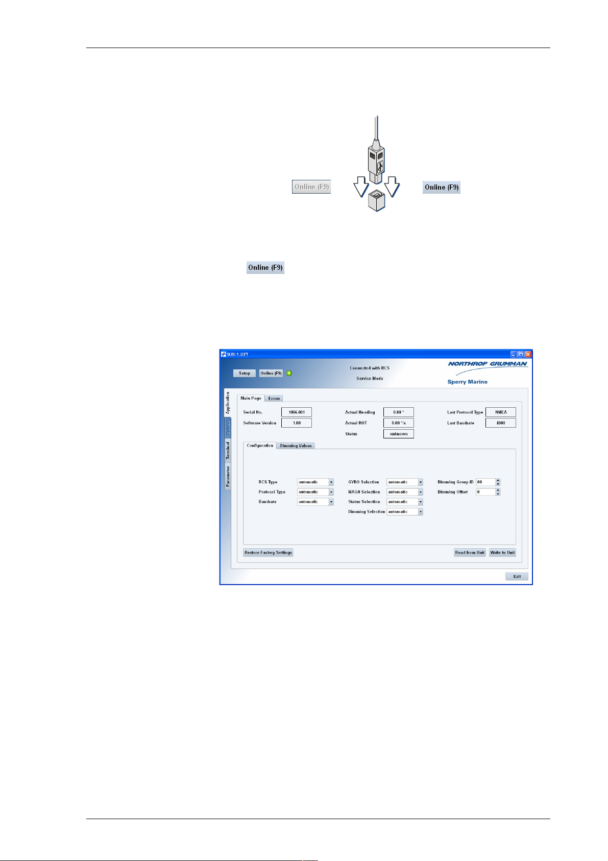
Analogue Compass Repeaters 056376/A
8. Plug in the USB cable at the PC and at the repeater’s service port.
The “Online” button should now become clickable (not greyed-out),
indicating that SUSI has found a device to connect to:
The LED icon next to the button will remain grey, as no connection
has been made yet.
9. Click to connect to the analogue repeater.
The LED icon should now change to green and the status line should
read “Connected with RCS”.
Upon connection, SUSI populates the Application tab with the analogue repeater application controls and displays the application’s
“Main Page”:
Configuring the Analogue Repeater with SUSI 6-3
Page 56
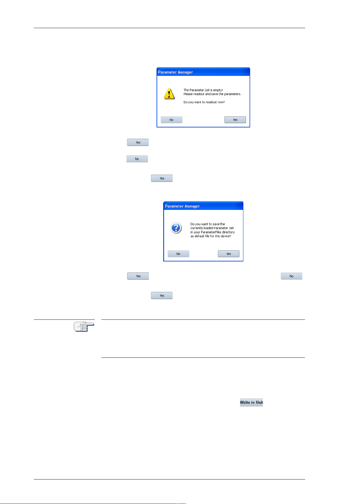
056376/A Analogue Compass Repeaters
Note
10. If the service PC has not previously been used to service an analogue repeater, a warning message will pop up, indicating that the
parameter list for the device is empty:
Click to read the current configuration from the repeater and
to set the Main page parameter controls accordingly, or
click if you intend to set all parameters manually in SUSI
first and write them to the repeater later.
11. If you clicked in the previous step, a dialogue box will pop
up, asking whether the parameters should be saved as default settings for this device:
Click . to save the parameters as default settings or
to cancel.
12. If you clicked in the previous step, the default settings are
now written to a file named “RCSdefault.xml“ in the sub-directory
“Parameter Files” in SUSI’s installation directory.
If a default parameter file for the analogue repeater already exists, e. g. if
the PC has been used previously to service a repeater, the above warning
message will not appear.
In this case, do not write back settings to the repeater before all parameters have been set as required for the repeater under service.
13. Using the Main Page controls, set the repeater configuration parameters and dimming values as required. An overview and detailed
descriptions of the parameters are given below (see “Configuration
Parameters” on page 6-6 and “Dimming Values” on page 6-12).
14. When all parameters are set as required, click to transfer the
settings to the repeater.
6-4 Configuring the Analogue Repeater with SUSI
Page 57
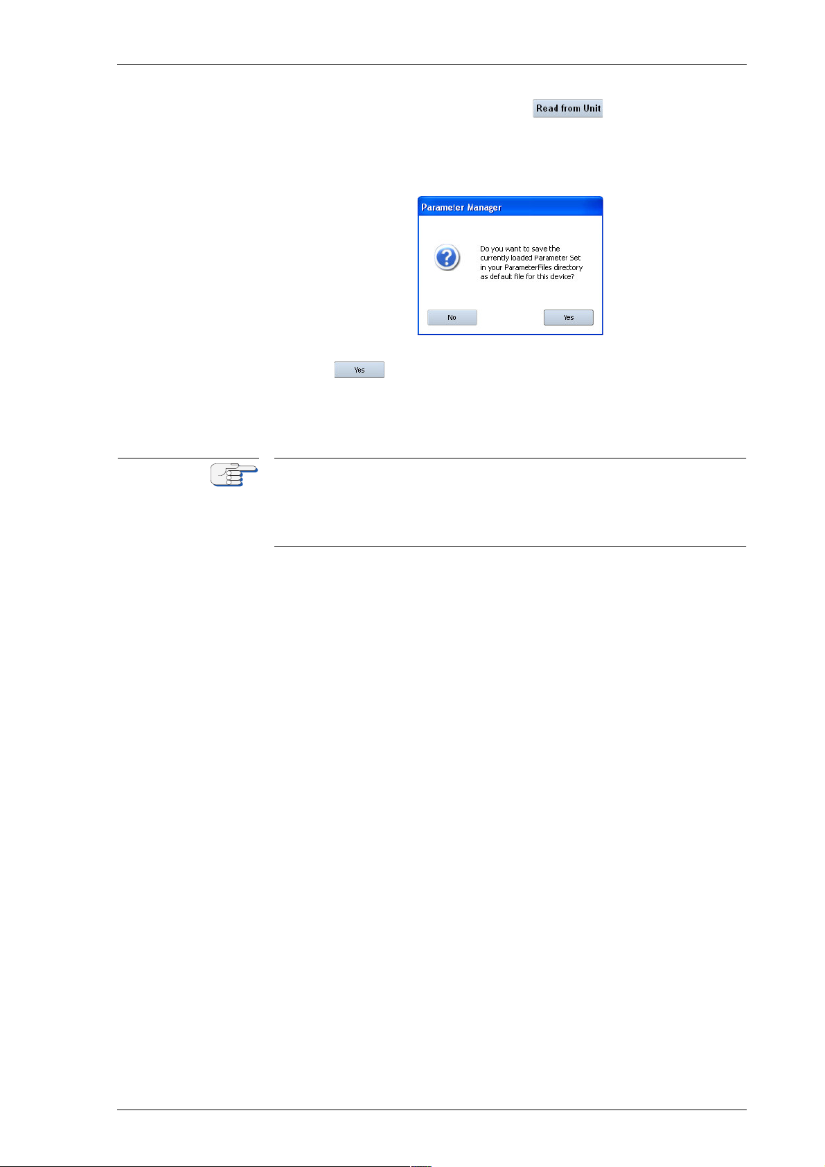
Analogue Compass Repeaters 056376/A
Note
15. To finish off the configuration, click in the SUSI application to read all configuration and calibration settings from the analogue repeater back into SUSI’s runtime memory.
A dialogue box will pop up, asking whether these parameters should
be saved as default settings for this device:
16. Click to save the parameters. The saved file is named “RCSdefault.xml“ and is located in the sub-directory “Parameter Files” in
SUSI’s installation directory.
To be able to retrieve and restore the configuration at a later point in
time, this file should be copied and saved to an appropriate location.
If a file “RCSdefault.xml“ already exists in SUSI’s “Parameter Files” subdirectory, it will be overwritten without further warning.
To be able to retrieve and restore the configuration at a later point in
time, rename the file “RCSdefault.xml“ and/or copy it from the “Parameter Files” sub-directory to a different location.
17. Fill out the analogue repeater setup table to retain an easily retrievable written record of the analogue repeater configuration.
18. Unplug the USB cable from the repeater and the service PC.
19. Power down the repeater and put the protective plug back on the
housing or reattach the cover to the connection box, respectively.
20. The configuration of the analogue repeater is now complete.
Configuring the Analogue Repeater with SUSI 6-5
Page 58
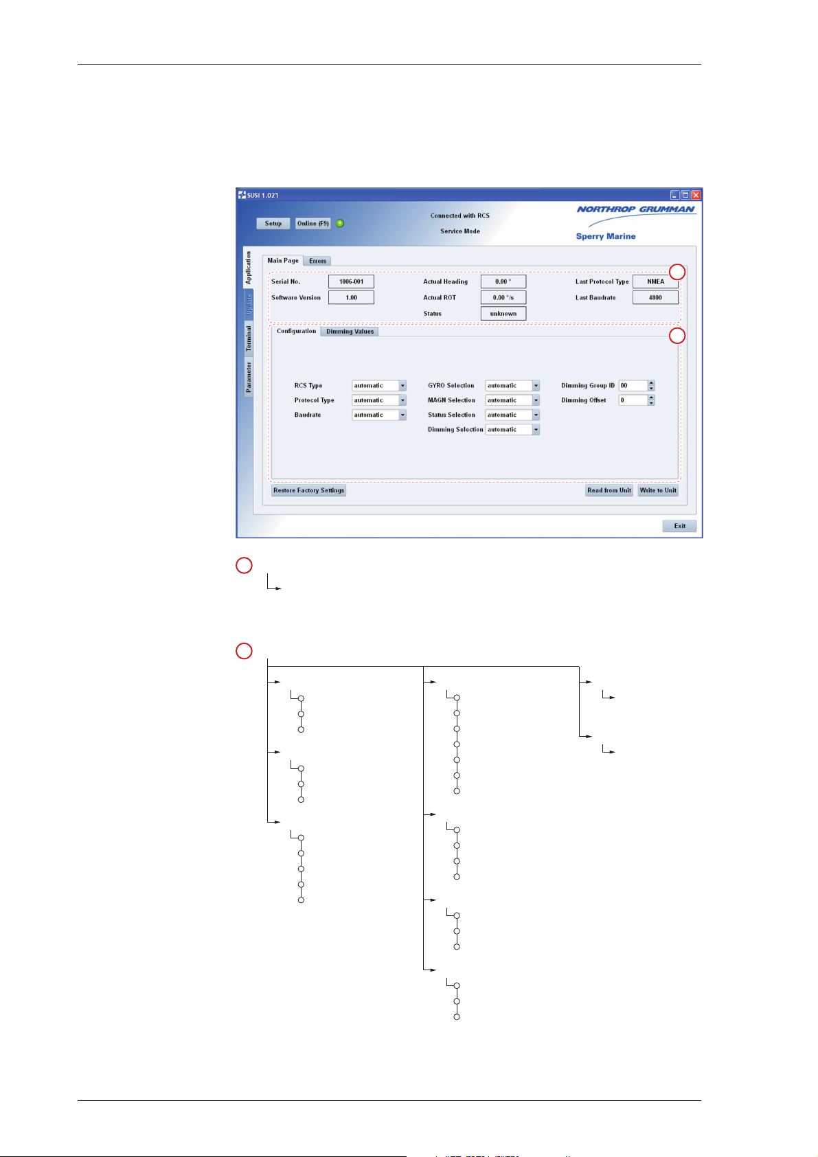
056376/A Analogue Compass Repeaters
1
2
Read-Only Controls:
Repeater Serial No. and Software Version,
Actual Heading, Rate of Turn and Selection Status,
Last Active Protocol Type and Baudrate
1
RCS Type
Gyro
Magnetic
2
automatic
1
GYRO Selection
Dimming Group ID
ID: 00 – 99
[default = 00]
Configuration Parameter Controls:
2
HEHDT
xxTHS
automatic
1
HETHS
xxHDT
GPTHS
GPHDT
Protocol Type
PLATH
NMEA
automatic
1
MAGN Selection
HCHDM
HCHDT
automatic
1
HCHDG
Status Selection
PPNSD
PPLAN
automatic
1
Dimming Selection
PPLAI
xxDDC
automatic
1
Baudrate
9600
4800
automatic
1
19200
38400
Dimming Offset
offset: -7 – +7
[default = 0]
1 = default setting
2 = default for magnetic heading repeater
6.3 Configuration Parameters
The analogue repeater application main page contains the settable controls to configure the repeater as required for the installation at hand.
Figure 6-1:
Controls on the
repeater application
main page
6-6 Configuration Parameters
Page 59

Analogue Compass Repeaters 056376/A
RCS Type
Sets the repeater device type.
Settings: automatic
Recognize heading data from gyrocompasses, THDs and
magnetic compasses. This is the factory default setting.
If data is received in the NMEA 0183/IEC 6116 protocol, the
repeater determines the active heading source according to
the following scheme:
Check the incoming data for $PPLAN or $PPNSD sentences
according to the “Status Selection” setting.
• If valid $PPLAN or $PPNSD sentences are found, check
the incoming data for heading from the selected source
(gyro or magnetic), according to the “GYRO Selection”
and “MAGN Selection” settings.
– If valid heading data is received from the selected
source, indicate heading and source.
– If no valid heading data is received from the selected
source, raise an error.
• If no valid $PPLAN or $PPNSD sentences are found,
check the incoming data for heading from any source
(gyro or magnetic), according to the “GYRO Selection”
and “MAGN Selection” settings.
– If valid heading data is received from one source
only, indicate the heading and source.
– If valid heading data is received from more than one
source, indicate the heading and source from the
highest prioritized source:
– Gyrocompass,
– THD,
– Magnetic Compass.
– If no valid heading data is received from any source,
raise an error.
Magnetic
Recognize magnetic heading data only. This is the required
setting for the magnetic heading repeater, type 5016-CC.
When installing a magnetic heading repeater, updating its
software or exchanging its PCB, make sure that this setting
is selected.
Gyro
Recognize heading data from gyrocompasses or THDs only.
This setting disables automatic fallback to magnetic heading when gyro heading is lost.
Configuration Parameters 6-7
Page 60

056376/A Analogue Compass Repeaters
Protocol Type
Selects the data protocol type.
Settings: automatic
Auto-detect the input protocol type, NMEA 0183/IEC 61162
or Plath binary.
NMEA
Recognize the NMEA 0183/IEC 61162 protocol only.
Plath
Recognize the Plath binary protocol only.
Baudrate
Selects the input baudrate (effective for the NMEA 0183/IEC 61162 protocol only).
Settings: automatic
Auto-detect the input baudrate.
4800
Receive at 4800 Bd. only.
9600
Receive at 9600 Bd. only.
19200
Receive at 19200 Bd. only.
38400
Receive at 38400 Bd. only.
6-8 Configuration Parameters
Page 61

Analogue Compass Repeaters 056376/A
Gyro Selection
Selects the accepted NMEA 0183/IEC 61162 sentences for gyrocompass
and THD headings.
Settings: automatic
No restriction. Accept, in the following order of priority:
- $HETHS,
- $--THS with any other talker ID (except HC),
- $HEHDT,
- $--HDT with any other talker ID (except HC).
If the talker ID is “GP”, the source is treated as a THD, in all
other cases, the source is treated as a gyrocompass.
HETHS
Accept $HETHS only.
xxTHS
Accept $--THS with any other talker ID (except HC).
HEHDT
Accept $HEHDT only.
xxHDT
Accept $--HDT with any other talker ID (except HC).
GPTHS
Accept $GPTHS only. The source is treated as a THD.
GPHDT
Accept $GPHDT only. The source is treated as a THD.
Magnetic Selection
Selects the accepted NMEA 0183/IEC 61162 sentences for magnetic compass heading.
Settings: automatic
No restriction. Accept, in the following order of priority:
- $HCHDT
- $HCHDM
- $HCHDG
HCHDT
Accept $HCHDT only.
HCHDM
Accept $HCHDM only.
HCHDM
Accept $HCHDG only.
Configuration Parameters 6-9
Page 62

056376/A Analogue Compass Repeaters
Status Selection
Selects the accepted NMEA 0183/IEC 61162 sentences for heading
source selection.
This setting is only effective in Sperry NAVIGAT gyrocompass systems,
which generate the respective proprietary “nav. status” sentences.
Settings: automatic
No restriction. Accept, in the following order of priority:
- $PPLAN
- $PPNSD
PPLAN
Accept $PPLAN only.
PPNSD
Accept $PPNSD only.
Dimming Selection
Selects the accepted NMEA 0183/IEC 61162 sentences for serial dimming
of the illumination brightness.
Settings: automatic
No restriction. Accept, in the following order of priority:
- $PPLAI (proprietary)
- $--DDC (standard)
PPLAI
Accept the proprietary $PPLAI sentence only.
xxDDC
Accept $--DDC with any talker ID.
Dimming Group ID
Assigns the repeater to a dim group.
This setting is only effective when the proprietary $PPLAI sentence is
used for serial dimming
Setting: 00 – 99
Select an ID between “01” and “99” to assign the repeater
to the respective dim group.
Selecting ID “00” lets the repeater accept any dim command
received, regardless of group assignment.
6-10 Configuration Parameters
Page 63

Analogue Compass Repeaters 056376/A
Dimming Offset
Sets a local offset for the brightness level.
Setting: -7 – +7
Select an offset as required to match the brightness of the
repeater to that of other equipment controlled through the
same dimming command device.
Offsets below 0 decrease, offsets above 0 increase the
repeater’s overall brightness by the corresponding number
of brightness levels.
As the analogue repeater’s illumination has eight discrete
brightness levels, an offset of -7 forces the minimum level
while an offset of 7 forces the maximum level at all times.
Note that adjusting the brightness with the DIM- and DIM+
keys also alters the dimming offset accordingly.
Configuration Parameters 6-11
Page 64
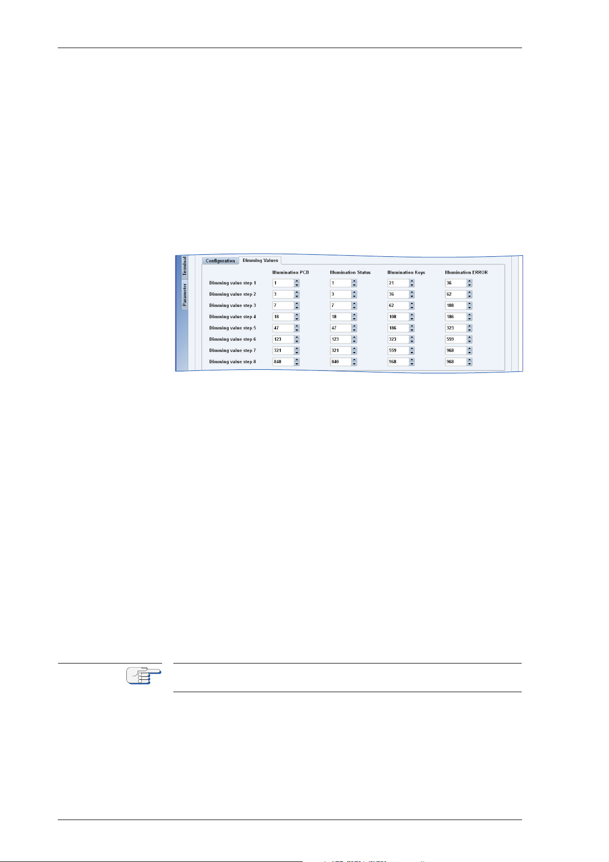
056376/A Analogue Compass Repeaters
Note
6.4 Dimming Values
The illumination intensities at the repeater ’s eight discrete brightness
levels are factory preset to provide a useful range of levels under most
lighting conditions, both at day and night.
However, to permit an optimum adaptation of the repeater to local lighting conditions, a configurable dimming value table is maintained in the
on-board memory.
For each brightness level (“dimming step”), the table holds a set of four
dimming values. These represent the illumination intensity for the card
backlight (“PCB”), the source indicators (“Status”), the DIM keys and the
error indicator.
Figure 6-2:
Repeater application
main page:
dimming values
Adjusting Dimming Values
The analogue repeater’s dimming values are preset to factory defaults
which should be suitable without further adjustment in most cases.
However, in certain situations, e.g. on an open deck or under subdued
lighting, a more useful range of brightness levels may be obtained if the
dimming values are altered.
To alter dimming values, edit the table entries directly or use the spin
controls to set them to the required values.
Each table entry may take any value between 0 (off) and 1000 (maximum
brightness). Due to the nonlinear brightness perception of the human
eye, it will be required to gradually increase the difference in value from
step to step in order to achieve even graduation of the brightness levels.
Alterations of the dimming values are transferred to the repeater immediately. This permits to directly observe the result of changes at the currently active brightness level.
Do not set the error indicator’s intensity to “0” at any dimming step.
This would disable the indicator at the respective step.
6-12 Dimming Values
Page 65
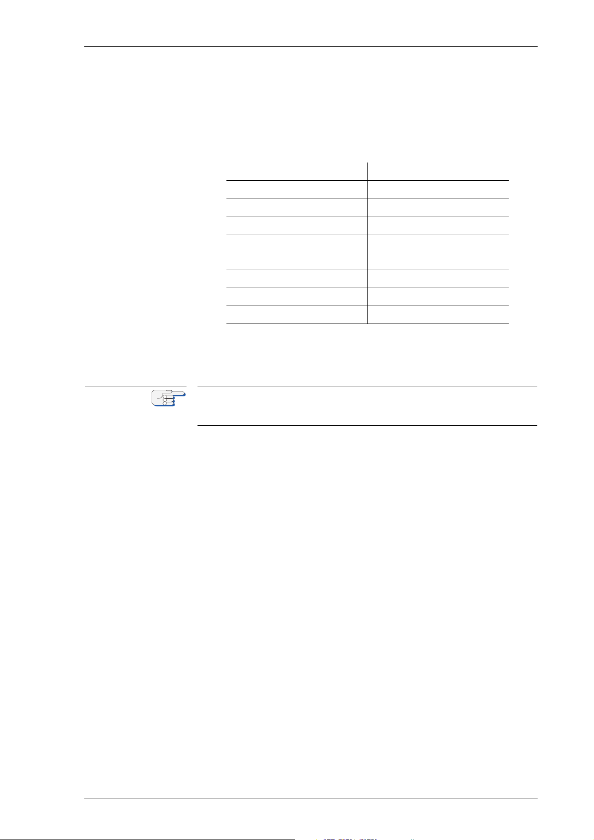
Analogue Compass Repeaters 056376/A
Note
Serial Dimming Command Evaluation
When serial dimming is used, the analogue repeater reads the commanded brightness percentage from the $--DDC or $PPLAI sentence,
respectively. At a dim offset of 0, the range of possible percentage values, is mapped to the repeater’s eight brightness levels as follows:
Table 6-1:
Serial dimming bright-
ness percentage to
repeater brightness
level mapping
commanded percentage repeater dimming step
00 – 11 1
12 - 24 2
25 - 36 3
37 - 49 4
50 - 61 5
62 - 74 6
75 - 86 7
87 - 99 8
If the dim offset is set to a value other than 0, via the setup or by adjusting the brightness with the DIM keys, the effective brightness of the
repeater is altered by the corresponding number of steps up or down.
The analogue repeater evaluates the brightness percentage field from
the $--DDC or $PPLAI sentences only. The dimming preset and colour
palette fields are ignored.
Dimming Values 6-13
Page 66

056376/A Analogue Compass Repeaters
6-14 Dimming Values
Page 67
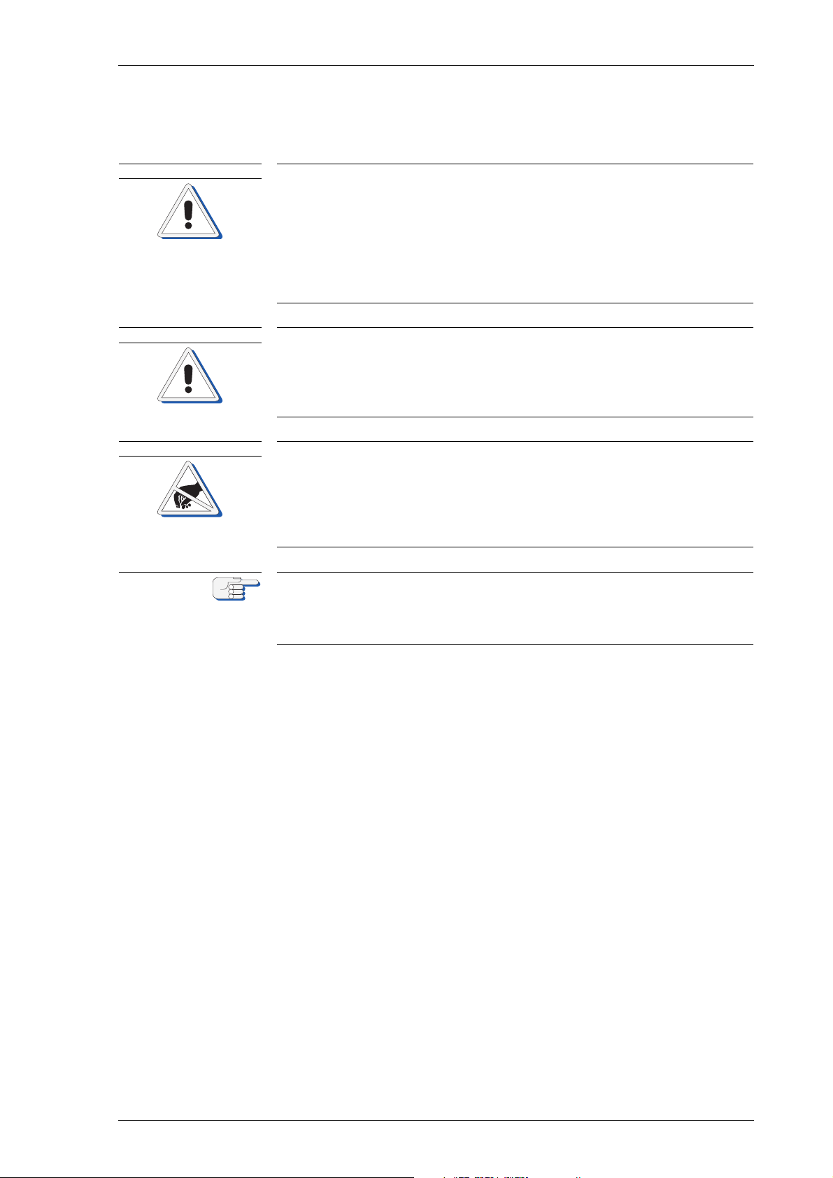
Analogue Compass Repeaters 056376/A
CAUTION
CAUTION
CAUTION
Note
Chapter 7: Troubleshooting
Risk of damage through unauthorized service
The housing of the bearing repeater 5016-CA is designed for increased
watertightness and shall therefore not be opened in the field.
Opening the housing in the field will diminish the watertightness and
may lead to condensation forming on the inside surfaces, especially the
top glass, at a later point in time.
Never open the bearing repeater housing in the field.
Always return a defective bearing repeater to Sperry Marine.
Risk of damage through unauthorized service
The analogue compass repeaters are complex electronic devices, which
are not serviceable in the field down to the level of individual circuit components.
Defective units must be sent back to Sperry Marine for repair.
Risk of damage of electrostatic-discharge-sensitive components
The analogue compass repeaters contain electrostatic sensitive components. Electrostatic discharge may permanently damage components.
When servicing an analogue compass repeater, take precautions to prevent electrostatic discharge.
Avoid touching any of the electronic circuitry.
The analogue compass repeaters are serviced and configured using the
Sperry Universal Setup Instrument (SUSI).
This tool is provided to authorized service personnel only and is generally not available to end-customers.
The analogue compass repeaters are complex electronic devices, which
are not serviceable in the field down to the level of individual circuit
components. Defective units must be sent back to Sperry Marine for
repair.
7.1 Basic Service Checks
Field service personnel shall only limit troubleshooting to the basic service checks given below.
All repeater types 5016-CA, -CB, -CC, -CD
• Continuity checks of wiring connections.
• Checks for short circuit or overload conditions or reversed polarity of
the external supply powers.
• Software-aided troubleshooting using Sperry Marine’s SUSI application, if explicitly instructed by Sperry Marine.
Basic Service Checks 7-1
Page 68

056376/A Analogue Compass Repeaters
Note
All repeaters, except bearing repeater, type 5016-CA
• Visual inspection of mechanical components, the PCB and wiring.
• Checks of the on-board supply voltages and I/O signals and data.
The presence of voltages, signals and data is indicated by diagnostic
LEDs on the PCB.
Exact voltage levels must be checked with a voltmeter true RMS.
The data content on serial I/O lines must be checked with the aid of suitable analysing tools, such as PC-based protocol interpreters or terminal
programs.
7-2 Basic Service Checks
Page 69
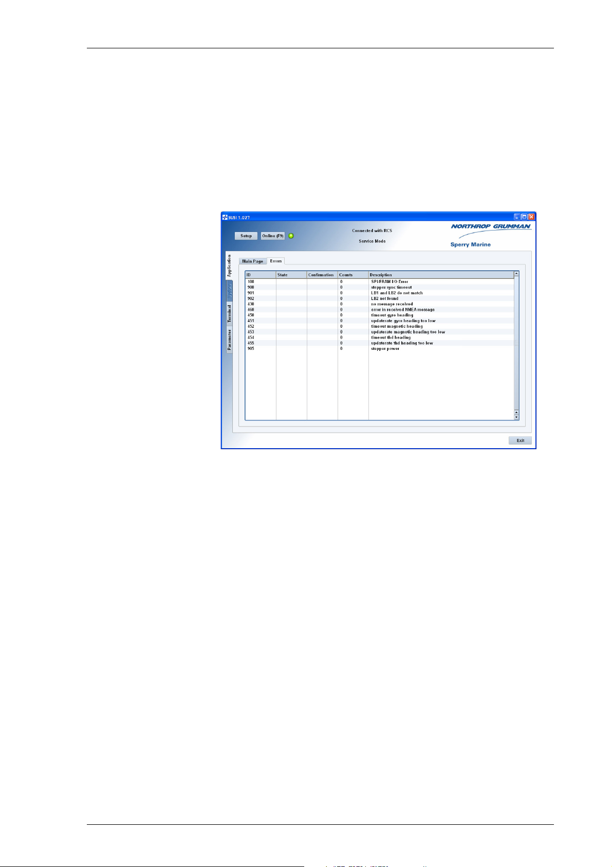
Analogue Compass Repeaters 056376/A
7.2 Viewing Error Information in SUSI
Analogue Repeater Error Page
When connected to an analogue repeater, the Sperry Universal Service
Instrument application (SUSI) provides an “Errors” page which displays
the current activity and confirmation state of a number of possible error
conditions and counts their occurrence since the last power-up:
Figure 7-1:
SUSI errors page
For errors which have not occurred since the last power-up, the state
and confirmation fields will be empty and the counter will read zero.
When an error condition is detected, the state field will read “active”. If
the error condition is no longer present, the state changes to “inactive”.
The confirmation field will always read “not acknowledged” for errors
which have occurred at least once, as the analogue repeater provides no
means to acknowledge an alarm.
As the Errors page is updated continuously, repeated occurrences of an
error lead to a corresponding increase of the error count.
The IDs and descriptions of the error conditions shown on SUSI’s
“Errors” page are given in table 7-1 below.
For more information on the SUSI application, refer to chapter 6 (“Configuration”) and to the SUSI Installation Guide included in the Sperry
Marine Client-CD 056800.
Viewing Error Information in SUSI 7-3
Page 70

056376/A Analogue Compass Repeaters
Error IDs and Descriptions
Table 7-1:
Analogue repeater
error IDs
ID description text cause corrective action
group 100: general errors
108 "SPI/FRAM I/O Er-
ror"
unable to read/
write configuration
settings
Cycle power.
Re-enter configuration parameters via
SUSI.
If error persists,
send return repeater to Sperry
Marine for exchange.
group 400: data I/O errors
430 "no message re-
ceived"
no data at input Check that valid
data is present at
the input.
450 "timeout gyro head-
ing"
gyro heading lost
or invalid while
gyro is active
Check that valid
gyro heading data
is present.
source
451 "updaterate gyro
heading too low"
gyro heading update rate < 1 Hz
Check gyro messages for invalid
data or checksum
faults.
Increase update
rate at source.
452 "timeout magnetic
heading"
453 "updaterate mag-
netic heading too
low"
454 "timeout thd head-
ing"
455 "updaterate thd
heading too low"
460 "error in received
NMEA message"
magnetic heading
lost or invalid while
magnetic compass
is active source
gyro heading update rate < 1 Hz
THD heading lost or
invalid while THD is
active source
THD heading update rate < 1 Hz
received data out of
range or not wellformed
Check that valid
magnetic compass
heading data is
present.
Check magnetic
heading messages
for invalid data or
checksum faults.
Increase update
rate at source.
Check that valid
THD heading data
is present.
Check THD messages for invalid
data or checksum
faults.
Increase update
rate at source.
Check whether all
messages contain
proper data.
7-4 Viewing Error Information in SUSI
Page 71

Analogue Compass Repeaters 056376/A
ID description text cause corrective action
group 900: stepper motor / synchronization errors
900 "stepper sync time-
out"
901 "LB1 and LB2 do
not match"
902 "LB2 not found" unable to detect 10°
905 "stepper power" stepper motor
synchronization
failed
zero position mismatch between 10°
and 360° card
card zero position
phase supply voltage too low
Re-initiate synchronization.
Cycle power.
If error persists after several attempts
to synchronize, return repeater to
Sperry Marine for
exchange.
Check actual voltage from 24 VDC
supply.
Viewing Error Information in SUSI 7-5
Page 72
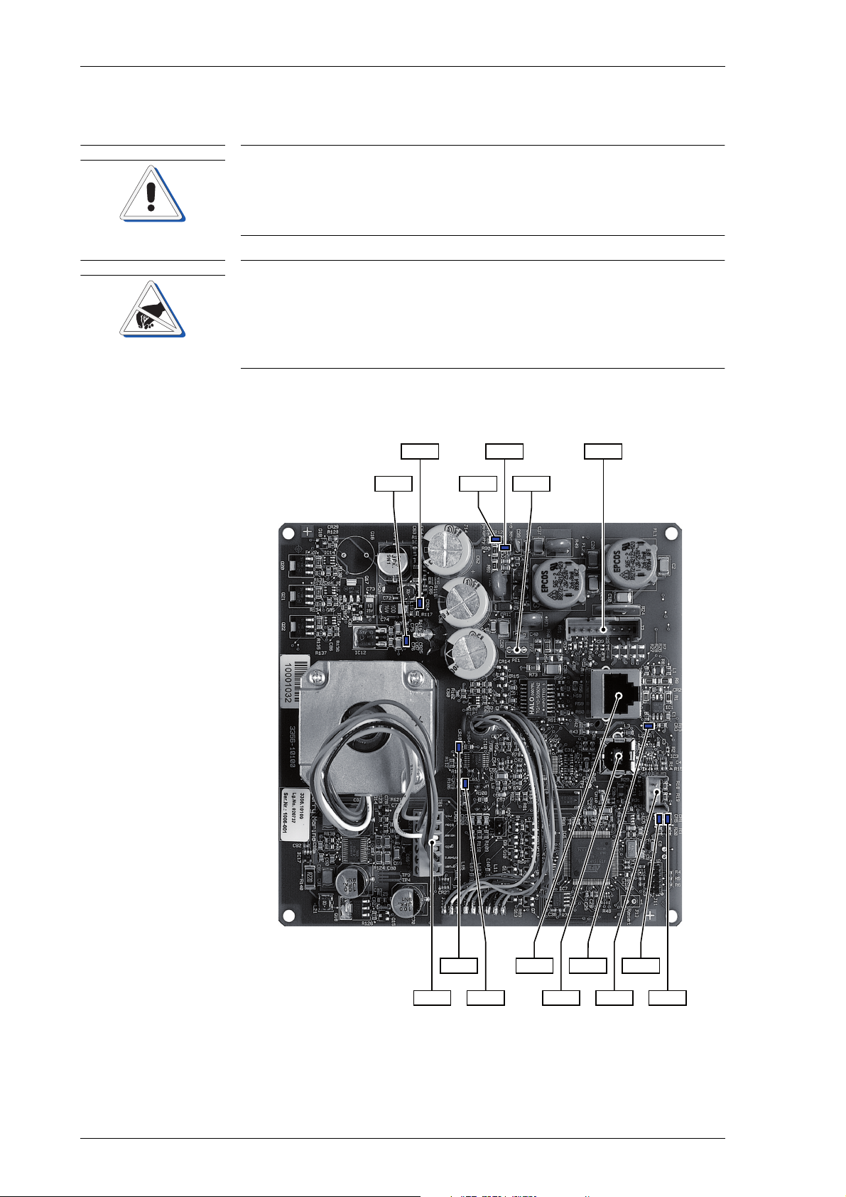
056376/A Analogue Compass Repeaters
CAUTION
CAUTION
CR 5
CR 1
CR 3
CR 11
CR 12
CR 24
CR 25
CR 18
CR 19
J 2
J 5
J 3
J 6TB 1
PE1
7.3 Location of Parts on the Analogue Repeater PCB
Risk of damage through unauthorized service
The analogue compass repeaters are complex electronic devices, which
are not serviceable in the field down to the level of individual circuit components.
Defective units must be sent back to Sperry Marine for repair.
Risk of damage of electrostatic-discharge-sensitive components
The analogue compass repeaters contain electrostatic sensitive components. Electrostatic discharge may permanently damage components.
When servicing an analogue compass repeater, take precautions to prevent electrostatic discharge.
Avoid touching any of the electronic circuitry.
Figure 7-2 below shows the locations of connectors and diagnostic LED
indicators on the repeater PCB.
Figure 7-2:
Location of parts
on the analogue
repeater PCB
7-6 Location of Parts on the Analogue Repeater PCB
Page 73

Analogue Compass Repeaters 056376/A
Terminal Boards and Connectors
Table 7-1:
Terminal boards
and connectors
Table 7-2:
Diagnostic LEDs
Function
TB 1 stepper motor connection terminal block
J 2 connector for repeater cable; connects to 24 VDC supply, Data
input, ext. USB service interface
J 3 Ethernet connector (for future use, currently not functional)
J 5 USB service interface connector
J 6 RS-232 service interface connector (for factory use only)
PE1 connector for repeater cable shield
Diagnostic LEDs
As an aid in troubleshooting, a number of diagnostic LED indicators are
provided on the PCB. These indicate general status information, the
presence of supply voltages and activity at the serial data input.
LED Colour Indication
CR 1 green system mode/status indication:
CR 5 green
both flashing at power-up: reading setup, initializing
both flashing permanently: fatal error
both off: normal operational mode
CR 5 on only: device in update mode
CR 3 green activity at data input
CR 11 green 24 VDC supply power present
CR 12 red reversed polarity 24 VDC supply power
CR 18 green 10° card at zero position must both be on
CR 19 green 360° card at zero position
after synchronization (cards at
North position)
CR 24 green on-board +5 VDC power present
CR 25 green on-board +3.3 VDC power present (Vcc)
Location of Parts on the Analogue Repeater PCB 7-7
Page 74

056376/A Analogue Compass Repeaters
7-8 Location of Parts on the Analogue Repeater PCB
Page 75

Analogue Compass Repeaters 056376/A
CAUTION
Note
Chapter 8: Corrective Maintenance
Risk of damage through unauthorized service
The analogue compass repeaters are complex electronic devices, which
are not serviceable in the field down to the level of individual circuit components.
Defective units must be sent back to Sperry Marine for repair.
The analogue compass repeaters are serviced and configured using the
Sperry Universal Setup Instrument (SUSI).
This tool is provided to authorized service personnel only and is generally not available to end-customers.
The analogue compass repeaters are complex electronic devices, which
are not serviceable in the field down to the level of individual circuit
components. Defective units must be sent back to Sperry Marine for
repair.
Should repeaters require to be re-configured, e.g. after installation of a
new compass source, field service attendance must be requested from
Sperry Marine directly or through an authorized Sperry Marine service
representative.
Maintenance by field service personnel is limited to the software-based
configuration and update procedures supported by the Sperry Universal
Software Instrument application (SUSI).
8.1 Updating the Repeater’s Firmware
The analogue compass repeater supports the uploading of firmware
files using SUSI. This allows to selectively update either the actual
repeater application software (“MCU-Application”) or the bootloader
(“MCU-Bootloader”).
SUSI is able to validate the provided files beforehand, making the file
upload a safe and reliable updating method. In case an upload should
fail for any reason, the repeater will remain fully functional, continuing
to run the previous firmware.
When new firmware is released for the analogue compass repeater,
authorized field service personnel will be provided with the required
files upon request.
Updating the Repeater’s Firmware 8-1
Page 76
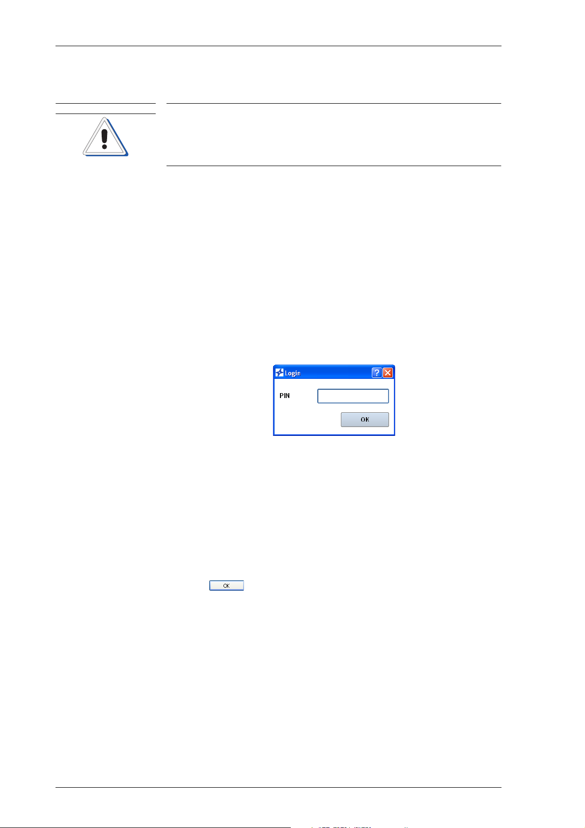
056376/A Analogue Compass Repeaters
CAUTION
Update Procedure
Risk of parameter settings loss
It cannot be guaranteed that the repeater’s configuration parameter settings are left intact during a firmware update.
Before updating firmware, record all parameter settings to be able to reenter them manually, if required.
To update an analogue compass repeater’s firmware:
1. If the repeater is currently powered up, switch off the power first.
2. Gain access to the repeaters USB service port receptacle:
– In case of a steering or magnetic heading repeater, remove the
plastic plug from the back of the housing to access the receptacle
on the repeater PCB. If necessary, unmount the repeater from the
console to make sure that the port is freely accessible for plugging and unplugging the USB cable.
– In case of a bearing or bulkhead repeater, open the repeater con-
nection box to access the receptacle inside the box.
3. At the PC, start up the SUSI application.
A login dialogue pops up:
4. You may either:
– Enter the PIN “20097”.
This will start up SUSI in the service mode.
Or:
– Leave the PIN empty.
This will start up SUSI in the “unknown login” mode.
In this mode, you may update the repeater firmware, but will not
be able to access the repeater’s configuration parameters without quitting and restarting SUSI in the service mode.
Click to continue.
5. SUSI’s main window now opens, with the “Application” tab displaying a list of supported devices:
8-2 Updating the Repeater’s Firmware
Page 77
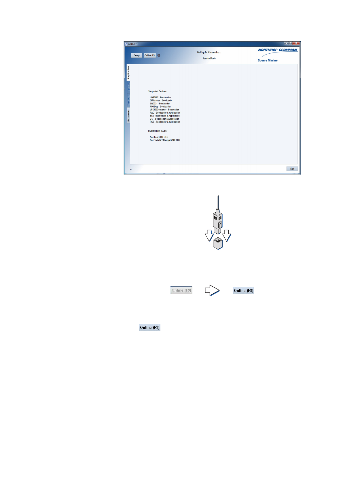
Analogue Compass Repeaters 056376/A
6. Plug in the USB cable at the PC and at the repeater’s service port.
7. Power up the repeater.
The “Online” button should now become clickable (not greyed-out),
indicating that SUSI has found a device to connect to:
The LED icon next to the button will remain grey, as no connection
has been made yet.
8. Click to connect to the repeater.
The LED icon should now change to orange and the status line
should read “Connected with RCS Bootloader”.
Upon connecting, SUSI opens the update tab:
Updating the Repeater’s Firmware 8-3
Page 78
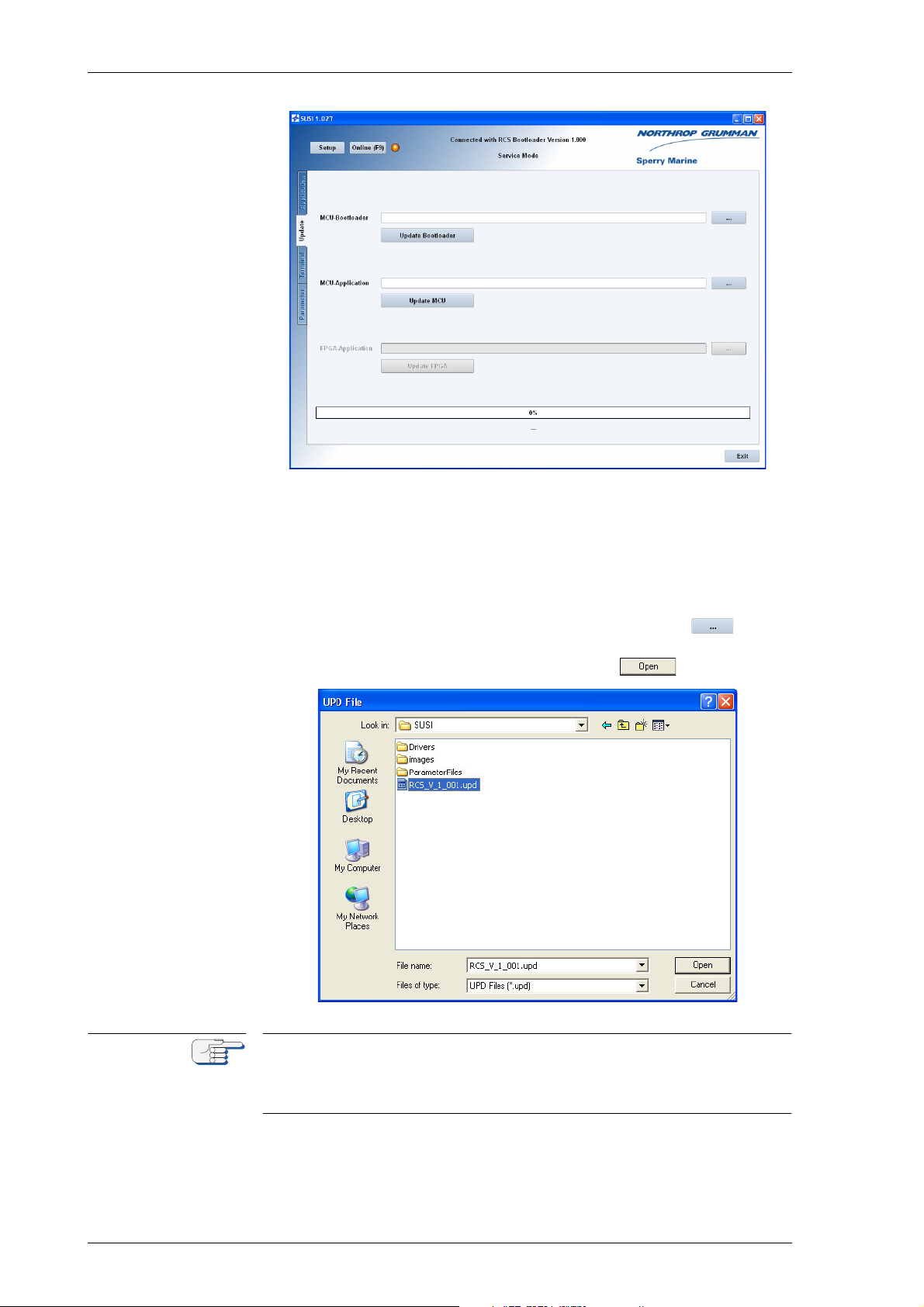
056376/A Analogue Compass Repeaters
Note
The update tab provides file browsers to select firmware update files
for the repeater’s system software (“MCU-Application”) and the
bootloader (“MCU-Bootloader”).
The option to update program code for an FPGA (“FPGA-Application“) is greyed out, as the repeater does not contain an FPGA.
9. Depending on whether you intend to update the repeater’s MCU
bootloader or its MCU application, click the respective button
to call up the file open dialogue. Then, navigate to the firmware
update file, select it in the dialogue and click .
The file open dialogue searches for files with the extension ”.upd” only.
In case the update file has been given another extension for any reason,
the filename, including the complete access path, must be entered manually in the respective text box of the update tab.
8-4 Updating the Repeater’s Firmware
Page 79
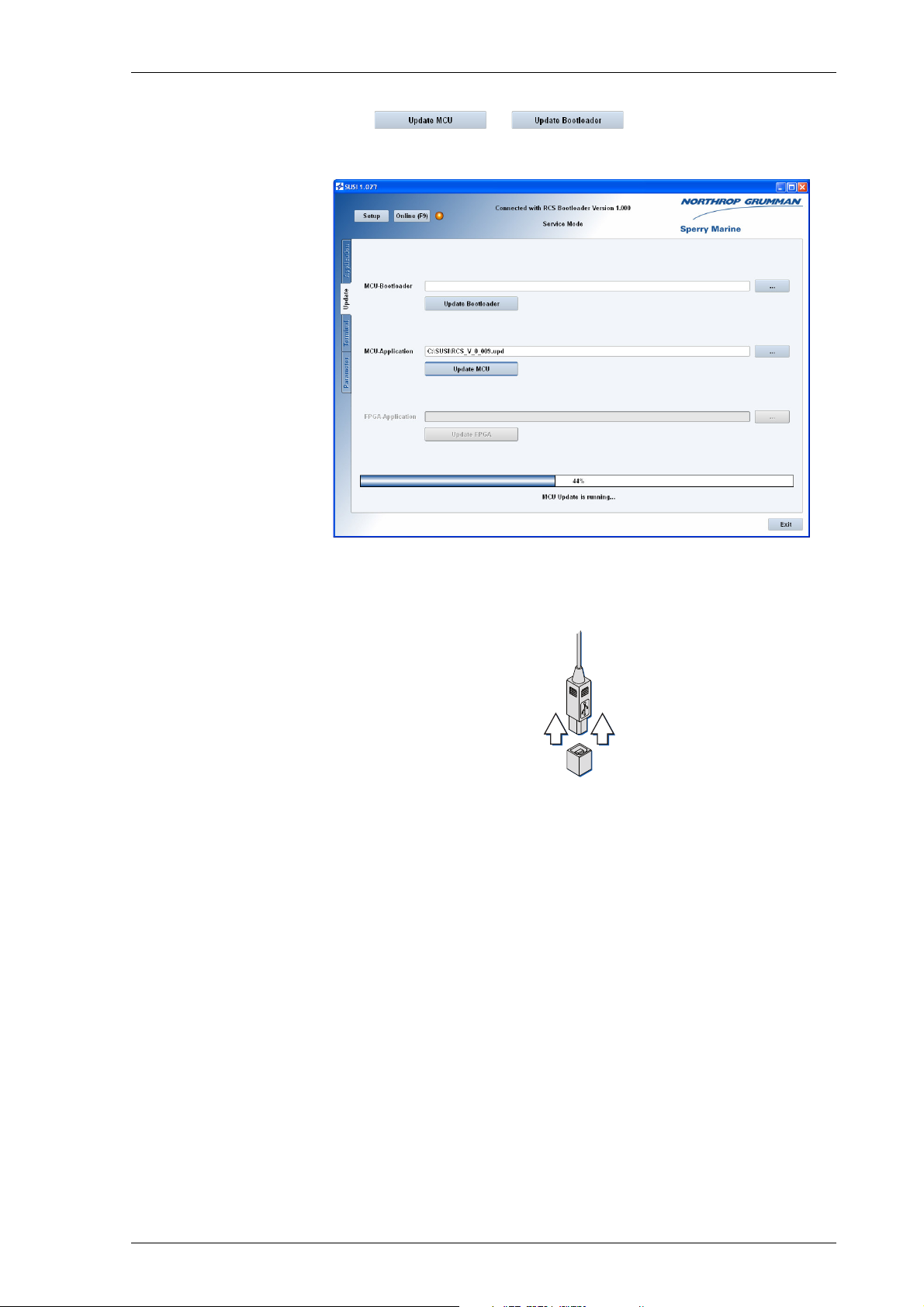
Analogue Compass Repeaters 056376/A
10. Click or respectively to initiate the
actual file upload. The bargraph at the bottom of the screen indicates
the progress of the update:
11. When the update is complete, the message “Update OK” will be
shown below the progress bar.
Unplug the USB cable at the PC and at the repeater’s service port.
12. The repeater now reboots with the new firmware.
Updating the Repeater’s Firmware 8-5
Page 80

056376/A Analogue Compass Repeaters
8-6 Updating the Repeater’s Firmware
Page 81

Analogue Compass Repeaters 056376/A
Note
Abbreviations
The following list contains abbreviations and shortcuts used in this manual and in displayed text of CDU menus.
A
1x1 frame Standard frame 96x96 mm
6 step/° scale measure setting of servomotor
A/DO-160 Section A, DO-160E, Environmental Conditions and
ACK Acknowledge alarms
ADA Name of a Programming Language
AIS Automatic Identification System
Test Procedures for Airborne Equipment
ANSI American National Standards Institute
approx. Approximately
ARS Attitude Reference System
ASME American Society of Mechanical Engineers
AZ Azimuth
B
BD Baud
Bd. Baud
BIT Built In Test
BIU Bus interface unit
BSH German Federal Maritime and Hydrographic Agency
btl. Bottle
(BSH)
C
C Celsius
CA Correction Angles
CAL. Calibration
cal. no. s. Calibration numbers
CCFL Cold Cathode Fluorescent Lamp
Abbreviations I
Page 82

056376/A Analogue Compass Repeaters
CDU Control and Display Unit
COG Course over ground
COMP Compass
Comp. Mon. Compass monitor
CONST. Constant
contd. Continued
corr. Correction
CORR. Correction
cos. Cosine
CR Carriage return
D
D00 D00 - D32 (D-Code, = Fault code)
DAC Digital analogue converter
DC Direct Current
D-Code Fault code (D00 - D32)
DGPS Differential GPS (see also GPS)
dia. Diameter
diff. Difference
DIFF. Difference
DIM dimmer
DIN Deutsche Industrie Norm (German Industrial Norm)
Dnn D00 - D32 (D-Code, = Fault code)
DNV Det Norske Veritas
DNV Naut-AW Det Norske Veritas Class notation for enhanced nauti-
DP Dynamic positioning
cal safety
dwg. drawing
E
E. East
EC Electronic compass
EC European Union Council
II Abbreviations
Page 83

Analogue Compass Repeaters 056376/A
ECCN Export Control Classification Number
ECDIS Electronic Chart Display and Information System
e.g. exempli gratia (for example)
EMC Environmental conditions
EM-Log Electromagnetic (speed) log
EN European Norm
ERR.STAT.BITS Validity check of fiber-optic sensor data status
ESD electrostatic discharge
etc. et cetera (and so on)
Ext Status In External status input port (TB 3.11)
ext. External
Ext. Sel. External selector switch
F
F Fahrenheit
fail. Failure
FIU Fiber optic interface unit (synonym for IPSU)
FL Line filter
Flash Non-volatile Memory
FMEA Failure mode effect analysis
FOG Fiber optic gyro
FRAM Ferro Electrical RAM (None volatile RAM)
FU Follow up
G
G Gyrocompass, single gyrocompass system
G1 Gyrocompass 1
G2 Gyrocompass 2
GAS Grounding avoidance system
Gen. General
GG Dual gyrocompass system
GGA NMEA sentence providing the GPS current fix data
Abbreviations III
Page 84

056376/A Analogue Compass Repeaters
GGM Dual gyrocompass/Magnetic compass system
GL Germanischer Lloyd
GLL Geographic position - latitude/longitude
GM Gyro- /Magnetic compass system
G/M headings Gyro /Magnetic compass headings
GMDSS Global Maritime Distress and Safety System
Gnd Ground
GNSS Global Navigation Satellite System
GPS Global Positioning System
GPS/AIS Global Positioning System / Automatic Identification
System
GT Gross tonnage
GYRO Gyrocompass
H
HCS Heading control system
HDG Heading, Magnetic
Hdg. Heading
hdg. Heading
Hdg. Diff Heading Difference (Alarm)
Hdg. Sel Heading selection; Selection of heading source device
HDG/G Heading/Gyro
HDT Heading, True
HMS Heading management system
HSC High speed craft
HSC-2000 Class notation for high speed craft
HTC Heading track control
Hz Hertz
I
I/O Input/Output
IC Integrated circuit
ICD Interface Control Document
IV Abbreviations
Page 85

Analogue Compass Repeaters 056376/A
ID Identifier
i.e. id est (that is)
IEC International Electro Technical Commission
IHO International Hydrographic Office.
IMO International Maritime Organization
IMU Inertial Measurement Unit
INS Integrated navigation system
INT HDG ONLY Internal heading only
INT/EXT HDG Internal or external heading
IP International Protection
IPD Illustrated Parts Data
IPL Illustrated Parts List
IPSU Interface and power supply unit
ISO International Organization for Standardization
J
J Jack (connector)
K
KF Kalman Filter
Kt. Knots
kt. Knots
kts. Knots
L
LAT Latitude
Lat. Latitude
lat. Latitude
LB1 light barrier 1
LB2 light barrier 2
LCD Liquid crystal display
LED Light Emitting Diode
Abbreviations V
Page 86

056376/A Analogue Compass Repeaters
LEHMK Lehmkuhl (transmission standard company Lehm-
kuhl)
LF Line feed
LFK Litef Faser Kreisel (Litef fiber optic gyroscope)
lgs longitudinal ground speed
lin. Linear
lon. Longitude
Lon. Longitude
LORAN Long Range Navigation
LORAN-C Long Range Navigation C
LSB Least significant Bit
lws longitudinal water speed
M
m Meter
M Magnetic compass
Mag Magnetic
MAG Magnetic Compass
Mag Hdg. Inp. Magnetic compass heading input
MAGN. Magnet
Magn. Cal. Tab Magnetic compass calibration table
Magn. DEV Magnetic deviation
Magn. VAR Magnetic variation
MAN. Manually
MarED Marine Equipment Directive
max. Maximal
MC Magnetic compass
MCU Microcontroller Unit
MED Marine Equipment Directive
MIN Minute
min Minute
min. Minimal
MMS Mechanical mode switch
VI Abbreviations
Page 87

Analogue Compass Repeaters 056376/A
Mod. Modul
Mod. Modus
Mod. 10/2 Gyrocompass container model 10/2
Mod. 10/3 Gyrocompass container model 10/3
Mod. 7/2 Gyrocompass container model 7/2
MSB Most significant Bit
MSC Maritime Safety Committee
MTBF Mean time between failure
N
N. North
NAUT-AW Class notation for enhanced nautical safety
Naut-HSC Class notation for high speed craft
Nav. Navigation
NFU None follow up
NG NAVIGAT
N Gyro North gyro
nm Nautic mile
NM Nautic mile
NMEA National Marine Electronics Association
NMEA NMEA format 4800 Bd
NMEA $--HDG NMEA $--HDG sentence
NMEA $--HDM NMEA $--HDM sentence
NMEA $--HDT NMEA $--HDT sentence
NMEA Sup.FAST SuperFAST serial data output
NMEA-GGA NMEA-GGA sentence
NMEA-GLL NMEA-GLL sentence
NMEA-HCHDG NMEA-HCHDG sentence
NMEA-HCHDM NMEA-HCHDM sentence
NMEA-HCHDT NMEA-HCHDT sentence
NMEA-HDG NMEA-HDG sentence
Abbreviations VII
Page 88

056376/A Analogue Compass Repeaters
NMEA-HDM NMEA-HDM sentence
NMEA-RMA NMEA-RMA sentence
NMEA-RMC NMEA-RMC sentence
n.o. Normally open
No. Number
NVR None Volatile RAM
O
Off Hdg Off heading alarm
Offs. Offset
op. Operational
OUTP Output
P
p. Pulse
Ph. Phase
P.Gnd Power ground
P/N Part number
PAL Pre-programmed IC
PCB Printed circuit board
PLATH Binary protocol of company C. Plath
PLCC Plastic leaded chip carrier
POS Position
POSITION N No position
pwr. Power
Q
QUICC Quad Integrated Communications Controller
QUART Quad Universal Asynchronous Receiver and Transmit-
ter
VIII Abbreviations
Page 89

Analogue Compass Repeaters 056376/A
R
RAC Rudder angle calibrator
RADAR Radio Detection and Ranging
RAI Rudder angle indicator
RAM Random Access Memory
RCS (Analogue) Repeater Compass System
Ref. Voltage Reference voltage
RM Recommended minimum navigation information
RMA Recommended minimum navigation information
NMEA sentence A
RMA No. Return Material Authorization number
RMB Recommended minimum navigation information
RMC Recommended minimum navigation information
RMS Root mean square
NMEA sentence B
NMEA sentence C
ROM Read Only Memory
ROR Rudder order status
ROT Rate of turn
ROTI Rate of turn indicator
rpm Revolutions per minute
RRR Russian River Register
RS-422 RS-422 serial data interface standard
RSA NMEA sentence for rudder set angle
RUD rudder angle graph
S
S. South
s Second
sc. Scaling
S/FAST M. Outp. Superfast / fast data output of magnetic compass
SAT-Log Satellite (speed) log
sc. Factor Scale factor
SCU Steering control unit
SEC Second
Abbreviations IX
heading
Page 90

056376/A Analogue Compass Repeaters
sec Second
SENS.D.M.OUTP. Output sentence format for magnetic compass head-
Sentence A self-contained line of data
SFA unit Steering failure alarm unit
S Gyro South gyro
sin. Sine
SMS Steering mode switch
SOD Serial output data
SOG Speed over ground (actual measured speed of
SOLAS Safety of life at sea
SoS Scope of supply
SOU Switch-over unit
ing at the sensor data output
advance of a vessel over the surface of the earth)
Sp. Speed
SPEED N No speed
SRAM Static RAM
SRD Sperry doppler speed log
SRP Sperry autopilot
Stat. Status
stb. Starboard
STW Speed through water (ship's speed, as measured rela-
tive to the water).
SUSI Sperry universal service instrument
SVDR Simplified voyage data recorder
SW Software
T
t. Time
TB TB 3.11 (external input port)
TB Terminal block
THD Transmitting Heading Device
thd Transmitting Heading Device
THS True heading and status
THS Transmitting heading system
X Abbreviations
Page 91

Analogue Compass Repeaters 056376/A
Temp. Temperature
TMC Transmitting magnet compass
TMC function Transmitting magnet compass function
TSS1 TSS1 protocol; Heading, pitch, roll, and heave mes-
TTL Transistor-transistor-logic
tws transversal water speed
TxD NMEA FAST Fast serial data output
UART Universal asynchronous receiver transmitter
UDR Universal digital repeater
UML Unified Modelling Language
sage in the commonly used TSS1 message format
U
USCG United states coast guard
V
V Volt
VAC Volt alternating current
Val. Values
VBW (Velocity bottom water) Dual ground/water speed
Vcc Voltage at the common collector
VDC Volt direct current
VDR Voyage data recorder
Ver. Version
VHW Velocity water speed and heading / speed through
VMS Voyage management system
VMS/ECDIS Voyage management system / electronic chart display
VOSS Vessel optimization & safety system
(water-referenced and ground-referenced speed data)
water
and information system
Vpp. Voltage peak to peak
VTG (Velocity over ground) Course over ground and
ground speed
(the actual course and speed relative to the ground)
VTS Vessel traffic service
Abbreviations XI
Page 92

056376/A Analogue Compass Repeaters
W
W Watt
W. West
w. with
w/ with
W/DO-160 Section W, DO-160E, Environmental Conditions and
Test Procedures for Airborne Equipment
w/o without
ws water speed, vector sum of lws and tws
X
X rate Roll rate
X/Y rates Roll and pitch rates
Y
Y rate Pitch rate
Z
Z/DO-160 Section Z, DO-160E, Environmental Conditions and
Test Procedures for Airborne Equipment
XII Abbreviations
Page 93

Analogue Compass Repeaters 056376/A
Note
Appendix
A Setup and Configuration Tables
The following tables (blank forms) are appended to this manual:
Designation Drawing No.
Analogue Repeater Compass Setup Table 5016-0125-02
After installation of the repeater, please return a filled-out copy of the
Setup Table to Sperry Marine for inclusion in the ship’s file.
When permanent changes are made to the system configuration, please
return an updated copy of the Setup Table to Sperry Marine.
B Drawings
The following drawings are appended to this manual:
Designation Drawing No.
Bearing Repeater Compass, Dimension Drawing 5016-0112-08
Steering / Magnetic Repeater Compass,
Dimension Drawing
Bulkhead Repeater Compass, Dimension Drawing 5016-0112-03
Bulkhead Repeater Bracket, Dimension Drawing 5016-0112-04
Watertight Installation, Dimension Drawing 5016-0112-05
Adaptor Kit for Retrofit of Type 4881,
Dimension Drawing
Connection Box, Dimension Drawing 4894-0112-04
Bearing Repeater Stand, Dimension Drawing 4622-0112-03
Bearing Repeater Bracket, Dimension Drawing 4890-0112-03
Adjustable Bearing Repeater Bracket,
Dimension Drawing
Azimuth Device PV 23, Dimension Drawing 2535-0112-01
Bearing Repeater Compass, Wiring Diagram 5016-0115-01
5016-0112-02
5016-0112-07
4905-0112-03
Steering / Magnetic Repeater Compass,
Wiring Diagram
Bulkhead Repeater Compass, Wiring Diagram 5016-0115-03
Connection Box for Bearing and Bulkhead Repeater
Compasses, Wiring Diagram
Compass System Repeater
Standard Connection Diagram
5016-0115-02
4894-0115-01
4932-0553-84
XIII
Page 94

056376/A Analogue Compass Repeaters
Note
All appended documents and drawings are revision-controlled separately at Sperry Marine.
In case of doubt, verify the current revision status of the drawings with
Sperry Marine. This manual’s revision status does not change when the
revision of an appended document or drawing changes.
XIV
Page 95
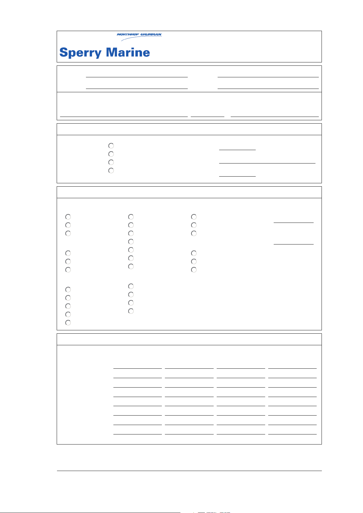
Analogue Compass Repeaters
Setup Table
Vessel:
IMO No.:
Service Station / Installer: Date / Signature:
Hull No.:
Shipyard:
/
Installation Reference
Repeater Type:
RCS Type
automatic
Magnetic
Gyro
Protocol Type
automatic
NMEA
Plath
Baudrate
automatic
4800
9600
19200
38400
5016-CA
5016-CB
5016-CC
5016-CD
Configuration Settings
GYRO Selection
automatic
HETHS
xxTHS
HEHDT
xxHDT
GPTHS
GPHDT
MAGN Selection
automatic
HCHDT
HCHDM
HCHDG
Serial Number:
Location:
Software Version:
Status Selection
automatic
PPLAN
PPNSD
Dimming Selection
automatic
xxDDC
PPLAI
005016-0125-002/A; 04 Feb 2015; Page 1 of 1
Dimming Group ID
ID:
Dimming Offset
offset:
Dimming Values
Ilum. PCB Ilum. Status Ilum. Keys Ilum. ERROR
Dimming Step 1
Dimming Step 2
Dimming Step 3
Dimming Step 4
Dimming Step 5
Dimming Step 6
Dimming Step 7
Dimming Step 8
Northrop Grumman Sperry Marine B.V.
Woltmanstr. 19, 20097 Hamburg, Germany
Tel.: +49-40-29900-0, Fax: +49-40-29900-146, E-mail: [email protected]
Page 96

Page 97
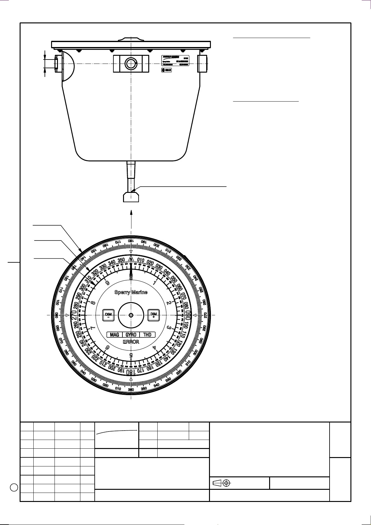
)
°
0
9
x
(4
2
1
Freie Kabellänge 2m
Free length of cable 2m
Magnetischer Schutzabstand
Mindestabstand vom:
Magnet-Regelkompass
Magnet-Steuerkompass
Reduz.Mindestabstand vom:
Magnet-Regelkompass
Magnet-Steuerkompass
0,80 m
0,50 m
0,50 m
0,30 m
Magnetic Safe Distance
Minimum Safe Distance to:
Standard Magnetic Compass
Steering Magnetic Compass
Minimum Safe Distance (reduced) to:
Standard Magnetic Compass
Steering Magnetic Compass
0,80 m
0,50 m
0,50 m
0,30 m
225
170
130
)
5
1
0
.2
1
.0
5
1
E
IN
R
A
M
Y
R
R
E
P
S
N
A
M
M
U
R
G
P
O
R
H
T
R
O
N
(
C
A 984159 03.02.2015 Ebe
REV ECO-No. DATE NAM
Voraus ±0,5° Ahead ±0,5°
NORTHROP GRUMMAN
Sperry Marine
HAMBURG GERMANY
DRAWING No.
DATE NAME
DRAWN
15.01.2015 Ebe
CHD
see ECO
DOS
5016-0112-08
STOCK No. REPLACEMENT FOR:
074914-0000-000
Gewicht/Weight: 5,5 kg
Schutzgrad/ Protection grade: IP56
DIMENSION DRAWING
Peiltochter
Typ 5016-CA
Bearing Repeater
Type 5016-CA
FIRST ANGLE
PROJECTION
DIMENSIONS IN
MILLIMETERS
SCALE
1:2,5
A4
SHEET
1
SHEETS
1
Page 98

Page 99
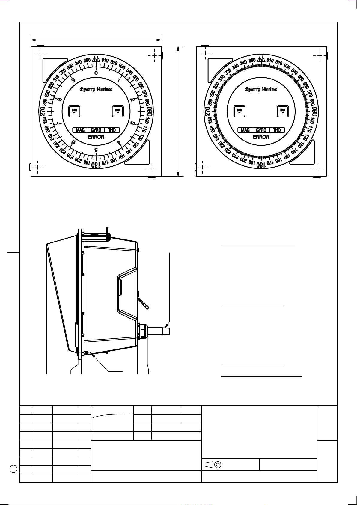
191,4
,4
1
9
1
Steuertochter mit Sonnenblende
Steering repeater with sun shield
Type 5016-AA (legacy), Sto.-No. 074881
Type 5016-CB, Sto.-No. 074915
)
9
0
0
.2
1
.1
4
2
E
IN
R
A
M
Y
R
R
E
P
S
N
A
M
M
U
R
G
P
O
R
H
T
C98415903.02.2015Ebe
R
O
N
B 983883 18.09.2013 Kie
(
C
A 982714 08.04.2010 Ebe
REV ECO-No. DATE NAM
2
5
0
5
Pultausschnitt quadratisch 181,5x181,5
Square cut out for console mounting 181,5x181,5
NORTHROP GRUMMAN
Sperry Marine
HAMBURG GERMANY
DRAWING No.
STOCK No. REPLACEMENT FOR:
M4
5016-0112-02
5
809
DATE NAME
DRAWN
24.11.2009 Ebe
CHD
see ECO
DOS
see above
Magnettochter mit Abdeckung
Magnetic heading repeater with cover
Type 5016-AB (legacy), Sto.-No. 074882
Type 5016-CC, Sto.-No. 074916
Magnetischer Schutzabstand
Mindestabstand vom:
m
3
e
l
m
b
3
a
c
e
f
g
n
o
lä
h
l
t
e
g
b
n
a
e
K
l
e
ie
e
e
r
r
F
F
Magnet-Regelkompass 0,75m
Magnet-Steuerkompass 0,50m
Reduz. Mindestabstand vom:
Magnet-Regelkompass 0,45m
Magnet-Steuerkompass 0,30m
Magnetic Safe Distance
Minimum Safe Distance to:
Standard Magnetic Compass 0,75m
Steering Magnetic Compass 0,50m
Minimum Safe Distance (reduced) to:
Standard Magnetic Compass 0,45m
Steering Magnetic Compass 0,30m
Gewicht/
Weight: 1,25 kg
Schutzgrad/ Protection grade:
Front: IP56
Rückseite/ Back: IP23
siehe/ see 5016-0112-05
DIMENSION DRAWING
Pulttochter
Steuertochter/ Magnettochter
Console Repeater
Steering/ Magnetic HDG repeater
FIRST ANGLE
PROJECTION
DIMENSIONS IN
MILLIMETERS
SCALE
1:2,5
A4
SHEET
1
SHEETS
1
Page 100

 Loading...