

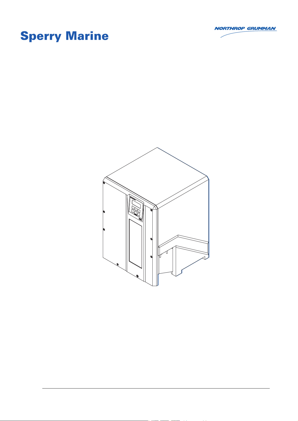
Sperry Marine NAVIGAT X MK1, 4914-CA, 74807, 4914-CC, 74811 Operation, Installation And Service Manual
Page 1
lйЙк~нбзеI=fелн~дд~нбзе=~еЗ=pЙкобЕЙ=j~ем~д
lкбЦбе~д=aзЕмгЙен~нбзе=L=hЙЙй=Сзк=cмнмкЙ=oЙСЙкЙеЕЙ
k^sfd^q u jh N
aбЦбн~д=dукзЕзгй~лл=pулнЙгл
qóéÉ=QVNQJ`^I=píçÅâ=kçK=TQUMT=~åÇ=qóéÉ=QVNQJ``I=píçÅâ=kçK=TQUNN
MQVNQJMNOUJMN
MRSPQPLcI=PM=pÉé=OMNQ
kзкнЬкзй=dкмгг~е=pйЙкку=j~кбеЙ=_KsK=EoЙйкЙлЙен~нбоЙ=lССбЕЙF
tзднг~елнкK=NV=√=aJOMMVT=√=e~гДмкЦI=dЙкг~еу
qЙдKW HQVJQMJOVV MMJM=√=c~сW HQVJQMJOVV MMJNQS=√=bJг~бдW лЙкобЕЙKЗЙ]лйЙккуKеЦЕKЕзг
Page 2
MRSPQPLc k^sfd^q u jh N
© 2014 Northrop Grumman Sperry Marine B.V.
This document and the information herein is the intellectual property of Northrop Grumman
Sperry Marine B.V. [NGSM BV] and it’s associate companies and may not be copied, reproduced
or translated without the express permission of NGSM BV.
Specifications were correct at time of press but may be varied in accordance with NGSM BV’s
policy of continuous product development.
Any technical content should be verified with NGSM BV.
Sperry Marine, with major engineering and support offices in New Malden, England, and
Hamburg, Germany, is part of the Northrop Grumman Navigation & Maritime Systems Division
N&MSD.
oЙоблбзе=oЙЕзкЗ
oÉîK a~íÉ oÉã~êâë
F 30 Sep 2014 Updated version, polar waters recommendations added, recom-
mended install and EMC conditons added, spare parts amended.
E 11 Nov 2013 Factory setting menu (technical pages) amended, service setup 2
amended, installation procedure and power-up function test amended.
D 11 Sep 2013 Updated version, new service setup options (Course Bus, THS/HDT,
ROT filter) added; technical data amended, checklist procedures
added, spare parts added; chapter removal/installation added.
C 08 May 2008 Added new options (AD10 output, alarm mute relay, speed filter).
B 17 Nov 2006 Removed gyrosphere installation/service instructions. These are now
contained in separate documents delivered with the respective gyrosphere and container.
All information regarding the master PCB refers to the new PCB, stock
no. 20672.
A 18 Jan 2005 Initial release.
Page 3

k^sfd^q u jh N MRSPQPLc
`зенЙенл
p~СЙну=fелнкмЕнбзел
p~СЙну=kзнбЕЙ=`зеоЙенбзелKKKKKKKKKKKKKKKKKKKKKKKKKKKKKKKKKKKKKKKKKKKKKKKKKKKKKKKKKKKKKKKKKKKKKKKK обб
dЙеЙк~д=p~СЙну=fеСзкг~нбзе=Сзк=нЬЙ=lйЙк~нзк KKKKKKKKKKKKKKKKKKKKKKKKKKKKKKKKKKKKKKKKK оббб
dЙеЙк~д=p~СЙну=fеСзкг~нбзе=Сзк=pЙкобЕЙ=mЙклзееЙдKKKKKKKKKKKKKKKKKKKKKKKKKKKKKKKKK сббб
`Ü~éíÉê=NW fенкзЗмЕнбзе
NKN pулнЙг=aЙлЕкбйнбзеKKKKKKKKKKKKKKKKKKKKKKKKKKKKKKKKKKKKKKKKKKKKKKKKKKKKKKKKKKKKKKKKKKKKKKKKKKKKKKKKKKK NJN
fенЙеЗЙЗ=rлЙ KKKKKKKKKKKKKKKKKKKKKKKKKKKKKKKKKKKKKKKKKKKKKKKKKKKKKKKKKKKKKKKKKKKKKKKKKKKKKKKKKKKKKKKKKKKKKKKNJN
kзн=fенЙеЗЙЗ=rлЙKKKKKKKKKKKKKKKKKKKKKKKKKKKKKKKKKKKKKKKKKKKKKKKKKKKKKKKKKKKKKKKKKKKKKKKKKKKKKKKKKKKKKKKKKNJN
NKO pулнЙг=lоЙкобЙп=~еЗ=j~бе=`згйзеЙенл KKKKKKKKKKKKKKKKKKKKKKKKKKKKKKKKKKKKKKKKKKKKKK NJO
i~ДЙд=~еЗ=нуйЙ=д~ДЙд KKKKKKKKKKKKKKKKKKKKKKKKKKKKKKKKKKKKKKKKKKKKKKKKKKKKKKKKKKKKKKKKKKKKKKKKKKKKKKKKKKKKKNJP
j~бе=ЕзгйзеЙенл KKKKKKKKKKKKKKKKKKKKKKKKKKKKKKKKKKKKKKKKKKKKKKKKKKKKKKKKKKKKKKKKKKKKKKKKKKKKKKKKKKKKKKKKNJQ
NKP aЙлбЦе=~еЗ=j~бе=cЙ~нмкЙлKKKKKKKKKKKKKKKKKKKKKKKKKKKKKKKKKKKKKKKKKKKKKKKKKKKKKKKKKKKKKKKKKKKKKKKK NJS
NKQ lйЙк~нбеЦ=mкбеЕбйдЙ KKKKKKKKKKKKKKKKKKKKKKKKKKKKKKKKKKKKKKKKKKKKKKKKKKKKKKKKKKKKKKKKKKKKKKKKKKKKKKKKKKK NJT
eЙ~ЗбеЦ=bккзк=i~нбнмЗЙ=`зккЙд~нбзе KKKKKKKKKKKKKKKKKKKKKKKKKKKKKKKKKKKKKKKKKKKKKKKKKKKKKKKKKKKKKKKNJV
NKR bс~гйдЙ=pулнЙг=`зеСбЦмк~нбзел KKKKKKKKKKKKKKKKKKKKKKKKKKKKKKKKKKKKKKKKKKKKKKKKKKKKKKKKKKKKNJNN
pн~еЗ~дзеЙ=dукзЕзгй~ллLqj`=pулнЙг KKKKKKKKKKKKKKKKKKKKKKKKKKKKKKKKKKKKKKKKKKKKKKKKKKKK NJNN
aм~д=k^sfd^qu jh N=dукзЕзгй~ллLqj`=pулнЙг KKKKKKKKKKKKKKKKKKKKKKKKKKKKKKKKKKKK NJNO
NKS qЙЕЬебЕ~д=a~н~KKKKKKKKKKKKKKKKKKKKKKKKKKKKKKKKKKKKKKKKKKKKKKKKKKKKKKKKKKKKKKKKKKKKKKKKKKKKKKKKKKKKKKKKKK NJNP
^ЕЕмк~ЕбЙл KKKKKKKKKKKKKKKKKKKKKKKKKKKKKKKKKKKKKKKKKKKKKKKKKKKKKKKKKKKKKKKKKKKKKKKKKKKKKKKKKKKKKKKKKKKKKKKKKKNJNP
lйЙк~нбзе~д=`Ь~к~ЕнЙкблнбЕл KKKKKKKKKKKKKKKKKKKKKKKKKKKKKKKKKKKKKKKKKKKKKKKKKKKKKKKKKKKKKKKKKKKKKKKKNJNP
bеобкзегЙен~д=oЙимбкЙгЙенлKKKKKKKKKKKKKKKKKKKKKKKKKKKKKKKKKKKKKKKKKKKKKKKKKKKKKKKKKKKKKKKKKKKKKNJNP
mзпЙк=pмййду KKKKKKKKKKKKKKKKKKKKKKKKKKKKKKKKKKKKKKKKKKKKKKKKKKKKKKKKKKKKKKKKKKKKKKKKKKKKKKKKKKKKKKKKKKKKKNJNQ
aбгЙелбзел=~еЗ=tЙбЦЬн KKKKKKKKKKKKKKKKKKKKKKKKKKKKKKKKKKKKKKKKKKKKKKKKKKKKKKKKKKKKKKKKKKKKKKKKKKKKKNJNR
fеймнл=L=lмнймнл KKKKKKKKKKKKKKKKKKKKKKKKKKKKKKKKKKKKKKKKKKKKKKKKKKKKKKKKKKKKKKKKKKKKKKKKKKKKKKKKKKKKKKKKK NJNR
NKT j~кбеЙ=bимбйгЙен=aбкЙЕнбоЙ=b`=aЙЕд~к~нбзе=зС=`зеСзкгбнуKKKKKKKKKKKKKKKK NJNT
`Ü~éíÉê=OW léÉê~íáçå
OKN lйЙк~нбеЦ=`зеЗбнбзел KKKKKKKKKKKKKKKKKKKKKKKKKKKKKKKKKKKKKKKKKKKKKKKKKKKKKKKKKKKKKKKKKKKKKKKKKKKKKKK OJN
OKO aáëéä~ó=~åÇ=léÉê~íáåÖ=hÉóë KKKKKKKKKKKKKKKKKKKKKKKKKKKKKKKKKKKKKKKKKKKKKKKKKKKKKKKKKKKKKKKKKKKKK OJO
`зенкзд=~еЗ=aблйд~у=rебн=E`arF KKKKKKKKKKKKKKKKKKKKKKKKKKKKKKKKKKKKKKKKKKKKKKKKKKKKKKKKKKKKKKKKKKK OJO
OKP bснЙке~д=`зенкзд=aЙобЕЙл KKKKKKKKKKKKKKKKKKKKKKKKKKKKKKKKKKKKKKKKKKKKKKKKKKKKKKKKKKKKKKKKKKKKKKKKKK OJP
OKQ mзпЙкJмй=pЙимЙеЕЙ KKKKKKKKKKKKKKKKKKKKKKKKKKKKKKKKKKKKKKKKKKKKKKKKKKKKKKKKKKKKKKKKKKKKKKKKKKKKKKKKKK OJQ
OKR pЙдЙЕнбеЦ=нЬЙ=^ЕнбоЙ=eЙ~ЗбеЦ=pзмкЕЙKKKKKKKKKKKKKKKKKKKKKKKKKKKKKKKKKKKKKKKKKKKKKKKKKKKKKK OJR
OKS ^ЗамлнбеЦ=нЬЙ=aблйд~у=_кбЦЬнеЙлл KKKKKKKKKKKKKKKKKKKKKKKKKKKKKKKKKKKKKKKKKKKKKKKKKKKKKKKKKKKK OJS
OKT lйнбзе~д=cмеЕнбзелKKKKKKKKKKKKKKKKKKKKKKKKKKKKKKKKKKKKKKKKKKKKKKKKKKKKKKKKKKKKKKKKKKKKKKKKKKKKKKKKKKKK OJS
jмнбеЦ=^д~кгл=oЙгзнЙду KKKKKKKKKKKKKKKKKKKKKKKKKKKKKKKKKKKKKKKKKKKKKKKKKKKKKKKKKKKKKKKKKKKKKKKKKKKK OJS
oЙоЙклбеЦ=нЬЙ=eЙ~ЗбеЦ=aблйд~у=ENUMш=зССлЙнFKKKKKKKKKKKKKKKKKKKKKKKKKKKKKKKKKKKKKKKKKKKKKKK OJS
oЙлЙннбеЦL^ЕвезпдЙЗЦбеЦ=~=`Йенк~д=t~нЕЬ=^д~кг KKKKKKKKKKKKKKKKKKKKKKKKKKKKKKKKKKKKKKK OJS
OKU léÉê~íáåÖ=jÉåì KKKKKKKKKKKKKKKKKKKKKKKKKKKKKKKKKKKKKKKKKKKKKKKKKKKKKKKKKKKKKKKKKKKKKKKKKKKKKKKKKKKKKKKK OJT
bенЙкбеЦ=~еЗ=nмбннбеЦ=нЬЙ=j~бе=jЙемKKKKKKKKKKKKKKKKKKKKKKKKKKKKKKKKKKKKKKKKKKKKKKKKKKKKKKKKK OJT
k~обЦ~нбеЦ=нЬЙ=jЙемKKKKKKKKKKKKKKKKKKKKKKKKKKKKKKKKKKKKKKKKKKKKKKKKKKKKKKKKKKKKKKKKKKKKKKKKKKKKKKKKKKK OJT
ááá
Page 4

MRSPQPLc k^sfd^q u jh N
pЙдЙЕнбеЦ=m~к~гЙнЙк=pЙннбеЦл KKKKKKKKKKKKKKKKKKKKKKKKKKKKKKKKKKKKKKKKKKKKKKKKKKKKKKKKKKKKKKKKKKKKKK OJU
bЗбнбеЦ=m~к~гЙнЙк=s~дмЙл KKKKKKKKKKKKKKKKKKKKKKKKKKKKKKKKKKKKKKKKKKKKKKKKKKKKKKKKKKKKKKKKKKKKKKKKKKKK OJU
OKV pЙдЙЕнбеЦ=~=aблйд~у=a~н~=m~ЦЙKKKKKKKKKKKKKKKKKKKKKKKKKKKKKKKKKKKKKKKKKKKKKKKKKKKKKKKKKKKKKKKKKK OJV
OKNM j~ем~д=pЙннбеЦл=jЙем KKKKKKKKKKKKKKKKKKKKKKKKKKKKKKKKKKKKKKKKKKKKKKKKKKKKKKKKKKKKKKKKKKKKKKKKKKK OJNM
`~йнбзе=Сзк=pЙдЙЕнбеЦ=~еЗ=bЗбнбеЦ KKKKKKKKKKKKKKKKKKKKKKKKKKKKKKKKKKKKKKKKKKKKKKKKKKKKKKKKKKKKKK OJNM
j~ем~д=pЙннбеЦл=У=lоЙкобЙп KKKKKKKKKKKKKKKKKKKKKKKKKKKKKKKKKKKKKKKKKKKKKKKKKKKKKKKKKKKKKKKKKKKKKKOJNN
j~ем~д=pЙннбеЦл=У=m~к~гЙнЙкл KKKKKKKKKKKKKKKKKKKKKKKKKKKKKKKKKKKKKKKKKKKKKKKKKKKKKKKKKKKKKKKKKK OJNP
OKNN rëÉê=pÉíìé KKKKKKKKKKKKKKKKKKKKKKKKKKKKKKKKKKKKKKKKKKKKKKKKKKKKKKKKKKKKKKKKKKKKKKKKKKKKKKKKKKKKKKKKKKKKKKK OJNT
rлЙк=pЙнмй=У=lоЙкобЙп KKKKKKKKKKKKKKKKKKKKKKKKKKKKKKKKKKKKKKKKKKKKKKKKKKKKKKKKKKKKKKKKKKKKKKKKKKKKK OJNT
rлЙк=pЙнмй=У=m~к~гЙнЙкл KKKKKKKKKKKKKKKKKKKKKKKKKKKKKKKKKKKKKKKKKKKKKKKKKKKKKKKKKKKKKKKKKKKKKKKKKK OJNU
`Ь~йнЙк=PW bккзкл=~еЗ=^д~кгл
PKN ^ä~êã=fåÇáÅ~íáçå KKKKKKKKKKKKKKKKKKKKKKKKKKKKKKKKKKKKKKKKKKKKKKKKKKKKKKKKKKKKKKKKKKKKKKKKKKKKKKKKKKKKKKKK PJN
^мЗбДдЙ=^д~кг=fеЗбЕ~нбзеKKKKKKKKKKKKKKKKKKKKKKKKKKKKKKKKKKKKKKKKKKKKKKKKKKKKKKKKKKKKKKKKKKKKKKKKKKKKKK PJN
sблм~д=^д~кг=fеЗбЕ~нбзе KKKKKKKKKKKKKKKKKKKKKKKKKKKKKKKKKKKKKKKKKKKKKKKKKKKKKKKKKKKKKKKKKKKKKKKKKKKKKKKK PJN
PKO ^ЕвезпдЙЗЦбеЦ=^д~кглLjмнбеЦ=нЬЙ=^мЗбДдЙ=^д~кгKKKKKKKKKKKKKKKKKKKKKKKKKKKKKKK PJO
^д~кг=^ЕвезпдЙЗЦЙ KKKKKKKKKKKKKKKKKKKKKKKKKKKKKKKKKKKKKKKKKKKKKKKKKKKKKKKKKKKKKKKKKKKKKKKKKKKKKKKKKKKK PJO
^д~кг=jмнЙ KKKKKKKKKKKKKKKKKKKKKKKKKKKKKKKKKKKKKKKKKKKKKKKKKKKKKKKKKKKKKKKKKKKKKKKKKKKKKKKKKKKKKKKKKKKKKKKKK PJO
PKP bêêçê=ãÉëë~ÖÉë KKKKKKKKKKKKKKKKKKKKKKKKKKKKKKKKKKKKKKKKKKKKKKKKKKKKKKKKKKKKKKKKKKKKKKKKKKKKKKKKKKKKKKKKKK PJP
`Ь~йнЙк=QW pЕЬЙЗмдЙЗ=j~бенЙе~еЕЙ
QKN j~бенЙе~еЕЙ=зС=нЬЙ=k^sfd^q=u=jh=N KKKKKKKKKKKKKKKKKKKKKKKKKKKKKKKKKKKKKKKKKKKKKKKKKKKKK QJN
`дЙ~ебеЦ=зС=`згй~лл=eзмлбеЦ KKKKKKKKKKKKKKKKKKKKKKKKKKKKKKKKKKKKKKKKKKKKKKKKKKKKKKKKKKKKKKKKKKKK QJN
`дЙ~ебеЦ=зС=^бк=fедЙн=dкбддKKKKKKKKKKKKKKKKKKKKKKKKKKKKKKKKKKKKKKKKKKKKKKKKKKKKKKKKKKKKKKKKKKKKKKKKKKKKKK QJN
QKO dукзлйЬЙкЙ=j~бенЙе~еЕЙ KKKKKKKKKKKKKKKKKKKKKKKKKKKKKKKKKKKKKKKKKKKKKKKKKKKKKKKKKKKKKKKKKKKKKKKKK QJO
NUJjзенЬ=j~бенЙе~еЕЙ KKKKKKKKKKKKKKKKKKKKKKKKKKKKKKKKKKKKKKKKKKKKKKKKKKKKKKKKKKKKKKKKKKKKKKKKKKKKKKK QJO
dукзлйЬЙкЙ=oЙйд~ЕЙгЙен=L=cбоЙJvЙ~к=j~бенЙе~еЕЙKKKKKKKKKKKKKKKKKKKKKKKKKKKKKKKKKKKKK QJP
`Ь~йнЙк=RW mкЙоЙенбоЙ=j~бенЙе~еЕЙ
RKN mкзнЙЕнбеЦ=нЬЙ=dукзлйЬЙкЙ=Скзг=a~г~ЦЙ KKKKKKKKKKKKKKKKKKKKKKKKKKKKKKKKKKKKKKKKKKKKKKK RJN
dукзлйЬЙкЙ=a~г~ЦЙ=Е~млЙЗ=Ду=iзп=qЙгйЙк~нмкЙл KKKKKKKKKKKKKKKKKKKKKKKKKKKKKKKKKKK RJN
dукзлйЬЙкЙ=a~г~ЦЙ=нЬкзмЦЬ=pЬмн=aзпе KKKKKKKKKKKKKKKKKKKKKKKKKKKKKKKKKKKKKKKKKKKKKKKKKKK RJO
RKO oЙгзобеЦ=нЬЙ=dукзлйЬЙкЙ=`зен~беЙк=Скзг=нЬЙ=`згй~лл=eзмлбеЦ KKKKKK RJP
RKP fелн~ддбеЦ=нЬЙ=dукзлйЬЙкЙ=`зен~беЙк=бе=нЬЙ=`згй~лл=eзмлбеЦKKKKKKKKKKKKK RJS
RKQ mзпЙкJмй=cмеЕнбзе=qЙлнKKKKKKKKKKKKKKKKKKKKKKKKKKKKKKKKKKKKKKKKKKKKKKKKKKKKKKKKKKKKKKKKKKKKKKKKKKKKK RJV
dукзлйЬЙкЙ=`мккЙен=mкЙдбгбе~кбЙл KKKKKKKKKKKKKKKKKKKKKKKKKKKKKKKKKKKKKKKKKKKKKKKKKKKKKKKKKKKKKKK RJV
m~кнлI=г~нЙкб~дл=~еЗ=нзздл=кЙимбкЙЗKKKKKKKKKKKKKKKKKKKKKKKKKKKKKKKKKKKKKKKKKKKKKKKKKKKKKKKKKKKK RJNM
mкзЕЙЗмкЙ KKKKKKKKKKKKKKKKKKKKKKKKKKKKKKKKKKKKKKKKKKKKKKKKKKKKKKKKKKKKKKKKKKKKKKKKKKKKKKKKKKKKKKKKKKKKKKKKKK RJNM
`Ь~йнЙк=SW oЙгзо~дLfелн~дд~нбзе=зС=`згйзеЙенл
SKN oЙгзобеЦ=pулнЙг=`згйзеЙенл=Скзг=нЬЙ=`згй~лл=KKKKKKKKKKKKKKKKKKKKKKKKKKKKK SJN
mкзЕЙЗмкЙ KKKKKKKKKKKKKKKKKKKKKKKKKKKKKKKKKKKKKKKKKKKKKKKKKKKKKKKKKKKKKKKKKKKKKKKKKKKKKKKKKKKKKKKKKKKKKKKKKKKK SJO
SKO fелн~ддбеЦ=pулнЙг=`згйзеЙенл=бенз=нЬЙ=`згй~ллKKKKKKKKKKKKKKKKKKKKKKKKKKKKKKKKK SJV
mкзЕЙЗмкЙ KKKKKKKKKKKKKKKKKKKKKKKKKKKKKKKKKKKKKKKKKKKKKKKKKKKKKKKKKKKKKKKKKKKKKKKKKKKKKKKKKKKKKKKKKKKKKKKKKKKK SJV
áî
Page 5

k^sfd^q u jh N MRSPQPLc
`Ü~éíÉê=TW pулнЙг=fелн~дд~нбзе
TKN fелн~ддбеЦ=oЙЕзггЙеЗ~нбзел KKKKKKKKKKKKKKKKKKKKKKKKKKKKKKKKKKKKKKKKKKKKKKKKKKKKKKKKKKKKKKKKKKK TJN
mд~ЕЙ=зС=fелн~дд~нбзе KKKKKKKKKKKKKKKKKKKKKKKKKKKKKKKKKKKKKKKKKKKKKKKKKKKKKKKKKKKKKKKKKKKKKKKKKKKKKKKKKKKKK TJN
sЙенбд~нбзе=L=qЙгйЙк~нмкЙ KKKKKKKKKKKKKKKKKKKKKKKKKKKKKKKKKKKKKKKKKKKKKKKKKKKKKKKKKKKKKKKKKKKKKKKKKKKK TJN
bдЙЕнкзг~ЦеЙнбЕ=fенЙкСЙкЙеЕЙKKKKKKKKKKKKKKKKKKKKKKKKKKKKKKKKKKKKKKKKKKKKKKKKKKKKKKKKKKKKKKKKKKKKKK TJN
sбДк~нбзе KKKKKKKKKKKKKKKKKKKKKKKKKKKKKKKKKKKKKKKKKKKKKKKKKKKKKKKKKKKKKKKKKKKKKKKKKKKKKKKKKKKKKKKKKKKKKKKKKKKKKK TJO
TKO jÉÅÜ~åáÅ~ä=fåëí~ää~íáçåKKKKKKKKKKKKKKKKKKKKKKKKKKKKKKKKKKKKKKKKKKKKKKKKKKKKKKKKKKKKKKKKKKKKKKKKKKKKK TJP
qк~елйзкнбеЦ=нЬЙ=`згй~лл=eзмлбеЦ KKKKKKKKKKKKKKKKKKKKKKKKKKKKKKKKKKKKKKKKKKKKKKKKKKKKKKKKKKKK TJP
fелн~ддбеЦ=нЬЙ=`згй~лл=eзмлбеЦ KKKKKKKKKKKKKKKKKKKKKKKKKKKKKKKKKKKKKKKKKKKKKKKKKKKKKKKKKKKKKKKKK TJP
TKP bдЙЕнкбЕ~д=fелн~дд~нбзе KKKKKKKKKKKKKKKKKKKKKKKKKKKKKKKKKKKKKKKKKKKKKKKKKKKKKKKKKKKKKKKKKKKKKKKKKKKKKKKK TJQ
^`=pмййду=mзпЙк=`зеСбЦмк~нбзе KKKKKKKKKKKKKKKKKKKKKKKKKKKKKKKKKKKKKKKKKKKKKKKKKKKKKKKKKKKKKKKKKK TJQ
tбкбеЦ=rй=нЬЙ=pулнЙг KKKKKKKKKKKKKKKKKKKKKKKKKKKKKKKKKKKKKKKKKKKKKKKKKKKKKKKKKKKKKKKKKKKKKKKKKKKKKKKKK TJR
TKQ dукзлйЬЙкЙ=fелн~дд~нбзе KKKKKKKKKKKKKKKKKKKKKKKKKKKKKKKKKKKKKKKKKKKKKKKKKKKKKKKKKKKKKKKKKKKKKKKKKKKK TJS
TKR fебнб~д=pулнЙг=`зеСбЦмк~нбзе KKKKKKKKKKKKKKKKKKKKKKKKKKKKKKKKKKKKKKKKKKKKKKKKKKKKKKKKKKKKKKKKKKKK TJT
`зеСбЦмк~нбзе=зС=нЬЙ=pулнЙг KKKKKKKKKKKKKKKKKKKKKKKKKKKKKKKKKKKKKKKKKKKKKKKKKKKKKKKKKKKKKKKKKKKKKKK TJT
cбе~дбтбеЦ=нЬЙ=fелн~дд~нбзе KKKKKKKKKKKKKKKKKKKKKKKKKKKKKKKKKKKKKKKKKKKKKKKKKKKKKKKKKKKKKKKKKKKKKKKKKKKKK TJU
TKS ^дбЦегЙен=bккзк=`зккЙЕнбзе KKKKKKKKKKKKKKKKKKKKKKKKKKKKKKKKKKKKKKKKKKKKKKKKKKKKKKKKKKKKKKKKKKKKKK TJV
TKT j~ЦеЙнбЕ=`згй~лл=`~дбДк~нбзеKKKKKKKKKKKKKKKKKKKKKKKKKKKKKKKKKKKKKKKKKKKKKKKKKKKKKKKKKKKKKKKTJNM
TKU fелн~дд~нбзе=`ЬЙЕв=mкзЕЙЗмкЙлKKKKKKKKKKKKKKKKKKKKKKKKKKKKKKKKKKKKKKKKKKKKKKKKKKKKKKKKKKKKKKKK TJNP
jЙЕЬ~ебЕ~д=fелн~дд~нбзе=`ЬЙЕв=mкзЕЙЗмкЙKKKKKKKKKKKKKKKKKKKKKKKKKKKKKKKKKKKKKKKKKKKKKKKKKKKTJNP
bдЙЕнкбЕ~д=fелн~дд~нбзе=`ЬЙЕв=mкзЕЙЗмкЙ KKKKKKKKKKKKKKKKKKKKKKKKKKKKKKKKKKKKKKKKKKKKKKKKKKKKKKTJNP
bеобкзегЙен~д=`зеЗбнбзел=`ЬЙЕв=mкзЕЙЗмкЙ KKKKKKKKKKKKKKKKKKKKKKKKKKKKKKKKKKKKKKKKKKKKKKTJNQ
pулнЙг=`зеСбЦмк~нбзе=`ЬЙЕв=mкзЕЙЗмкЙKKKKKKKKKKKKKKKKKKKKKKKKKKKKKKKKKKKKKKKKKKKKKKKKKKKKKTJNQ
`Ü~éíÉê=UW pулнЙг=`зеСбЦмк~нбзе
UKN `зеСбЦмк~нбзе=jЙем=J=pЙкобЕЙ=pЙнмй=N KKKKKKKKKKKKKKKKKKKKKKKKKKKKKKKKKKKKKKKKKKKKKKKKKKKK UJN
pЙнмй=^ЕЕЙлл=`зЗЙKKKKKKKKKKKKKKKKKKKKKKKKKKKKKKKKKKKKKKKKKKKKKKKKKKKKKKKKKKKKKKKKKKKKKKKKKKKKKKKKKKKKK UJN
pЙкобЕЙJpЙнмй=N=У=lоЙкобЙпKKKKKKKKKKKKKKKKKKKKKKKKKKKKKKKKKKKKKKKKKKKKKKKKKKKKKKKKKKKKKKKKKKKKKKKK UJO
pЙкобЕЙ=pЙнмй=N=У=m~к~гЙнЙкл KKKKKKKKKKKKKKKKKKKKKKKKKKKKKKKKKKKKKKKKKKKKKKKKKKKKKKKKKKKKKKKKKKKKK UJS
UKO pЙкобЕЙ=fеСз=jЙем=J=pЙкобЕЙ=pЙнмй=O KKKKKKKKKKKKKKKKKKKKKKKKKKKKKKKKKKKKKKKKKKKKKKKKKKKKK UJOM
pЙкобЕЙ=pЙнмй=O=У=^ЕЕЙлл=`зЗЙ KKKKKKKKKKKKKKKKKKKKKKKKKKKKKKKKKKKKKKKKKKKKKKKKKKKKKKKKKKKKKKKK UJOM
pЙкобЕЙ=pЙнмй=O=У=lоЙкобЙпKKKKKKKKKKKKKKKKKKKKKKKKKKKKKKKKKKKKKKKKKKKKKKKKKKKKKKKKKKKKKKKKKKKKKK UJON
pЙкобЕЙ=pЙнмй=O=У=m~к~гЙнЙкл KKKKKKKKKKKKKKKKKKKKKKKKKKKKKKKKKKKKKKKKKKKKKKKKKKKKKKKKKKKKKKKKKKK UJOO
UKP c~Ензку=pЙннбеЦл=jЙем=EqЙЕЬебЕ~д=m~ЦЙлF KKKKKKKKKKKKKKKKKKKKKKKKKKKKKKKKKKKKKKKKKKKKK UJOQ
pЙнмй=^ЕЕЙлл=`зЗЙKKKKKKKKKKKKKKKKKKKKKKKKKKKKKKKKKKKKKKKKKKKKKKKKKKKKKKKKKKKKKKKKKKKKKKKKKKKKKKKKKKK UJOQ
qЙЕЬебЕ~д=m~ЦЙл=У=lоЙкобЙп KKKKKKKKKKKKKKKKKKKKKKKKKKKKKKKKKKKKKKKKKKKKKKKKKKKKKKKKKKKKKKKKKKKKKK UJOQ
qЙЕЬебЕ~д=m~ЦЙл=У=m~к~гЙнЙкл KKKKKKKKKKKKKKKKKKKKKKKKKKKKKKKKKKKKKKKKKKKKKKKKKKKKKKKKKKKKKKKKKKK UJOR
`Ü~éíÉê=VW qкзмДдЙлЬззнбеЦ
VKN qкзмДдЙлЬззнбеЦ=fелнкмЕнбзел KKKKKKKKKKKKKKKKKKKKKKKKKKKKKKKKKKKKKKKKKKKKKKKKKKKKKKKKKKKKKKKKKKK VJN
VKO içÅ~íáçå=çÑ=m~êíë=çå=íÜÉ=j~ëíÉê=m`_ KKKKKKKKKKKKKKKKKKKKKKKKKKKKKKKKKKKKKKKKKKKKKKKKKKKKKK VJO
bсЕЬ~еЦЙ~ДдЙ=`згйзеЙенлKKKKKKKKKKKKKKKKKKKKKKKKKKKKKKKKKKKKKKKKKKKKKKKKKKKKKKKKKKKKKKKKKKKKKKKKK VJP
`зееЙЕнзклKKKKKKKKKKKKKKKKKKKKKKKKKKKKKKKKKKKKKKKKKKKKKKKKKKKKKKKKKKKKKKKKKKKKKKKKKKKKKKKKKKKKKKKKKKKKKKKKKK VJP
qЙлн=oЙлблнзк=L=qкбгйзнлKKKKKKKKKKKKKKKKKKKKKKKKKKKKKKKKKKKKKKKKKKKKKKKKKKKKKKKKKKKKKKKKKKKKKKKKKKKKKKK VJQ
aб~ЦезлнбЕ=ibaлKKKKKKKKKKKKKKKKKKKKKKKKKKKKKKKKKKKKKKKKKKKKKKKKKKKKKKKKKKKKKKKKKKKKKKKKKKKKKKKKKKKKKKKKKK VJQ
î
Page 6

MRSPQPLc k^sfd^q u jh N
`Ü~éíÉê=NMW `зккЙЕнбоЙ=j~бенЙе~еЕЙ
NMKN bсЕЬ~еЦбеЦ=нЬЙ=pулнЙг=pзСнп~кЙ KKKKKKKKKKKKKKKKKKKKKKKKKKKKKKKKKKKKKKKKKKKKKKKKKKKKKKKKK NMJN
NMKO oЙйд~ЕбеЦ=pзЕвЙнЙЗ=f`лKKKKKKKKKKKKKKKKKKKKKKKKKKKKKKKKKKKKKKKKKKKKKKKKKKKKKKKKKKKKKKKKKKKKKKKKKKK NMJO
`Ü~éíÉê=NNW k^sfd^q u=jhN=pé~êÉ=m~êíë
NNKN fддмлнк~нЙЗ=m~кнл=iблн=EfmiF=lоЙкобЙп KKKKKKKKKKKKKKKKKKKKKKKKKKKKKKKKKKKKKKKKKKKKKKKKKKKKKK NNJN
^ДДкЙоб~нбзел
^ййЙеЗбс
^ pЙнмй=~еЗ=`зеСбЦмк~нбзе=q~ДдЙл
_ aк~пбеЦл
îá
Page 7
k^sfd^q u jh N MRSPQPLc
a^kdbo
t^okfkd
`^rqflk
kçíÉ
p~СЙну=fелнкмЕнбзел
p~СЙну=kзнбЕЙ=`зеоЙенбзел
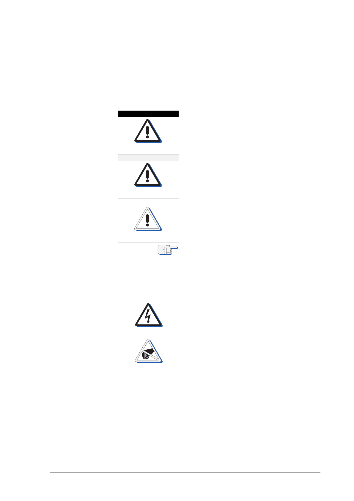
The following safety notice conventions are followed throughout this
manual:
A a~åÖÉê notice begins with the named type of
danger and contains an operating or maintenance procedure, practice, condition, statement,
etc., which, if not strictly observed, пбдд=кЙлмдн=бе=
беамку=зк=ЗЙ~нЬ=зС=йЙклзееЙдK
A t~кебеЦ notice begins with the named type of
warning and contains an operating or maintenance procedure, practice, condition, statement,
etc., which, if not strictly observed, ЕзмдЗ=кЙлмдн=
бе=беамку=зк=ЗЙ~нЬ=зС=йЙклзееЙдK
A `~мнбзе notice begins with the named type of
caution and contains an operating or maintenance procedure, practice, condition, statement,
etc., which, if not strictly observed, ЕзмдЗ=кЙлмдн=
бе=З~г~ЦЙ=нзI=зк=ЗЙлнкмЕнбзе=зС=ЙимбйгЙенK
A kçíÉ contains an essential operating or maintenance procedure, condition or statement,
which is considered important enough to be
highlighted.
Special safety symbols may be used in this
manual to indicate:
oблв=зС=ЙдЙЕнкбЕ~д=лЬзЕвK
Used in conjunction with a a~åÖÉê or t~кебеЦ
notice.
Electrical components sensitive to electrostatic
discharge.
Used in conjunction with a `~мнбзе notice.
p~СЙну=fелнкмЕнбзел îáá
Page 8
MRSPQPLc k^sfd^q u jh N
t^okfkd
t^okfkd
t^okfkd
`^rqflk
`^rqflk
`^rqflk
dЙеЙк~д=p~СЙну=fеСзкг~нбзе=Сзк=нЬЙ=lйЙк~нзк
oблв=зС=ЗЙоб~нбзе
kЙоЙк=кЙду=зе=зеЙ=ЬЙ~ЗбеЦ=лзмкЕЙ=~дзеЙ=нз=е~обЦ~нЙ=~=оЙллЙдK
^дп~ул=ЕзеСбкг=нЬЙ=йд~млбДбдбну=зС=нЬЙ=k^sfd^q u jh N=ЬЙ~ЗбеЦ=~еЗ=нЬЙ=
лйЙЙЗ=~еЗ=йзлбнбзе=беймн=З~н~=~Ц~белн=~дд=~о~бд~ДдЙ=~бЗл=нз=е~обЦ~нбзеK
iбгбнЙЗ=ЬЙ~ЗбеЦ=З~н~=~ЕЕмк~Еу=ЗмкбеЦ=лЙнндбеЦ=нбгЙ
^СнЙк=~=йзпЙкJмй=Скзг=ЕздЗI=нЬЙ=k^sfd^q u jh N=кЙимбкЙл=~=лЙнндбеЦ=нбгЙ=
зС=нЬкЙЙ=Ьзмкл=ДЙСзкЙ=кЙдб~ДдЙ=ЬЙ~ЗбеЦ=З~н~=бл=~о~бд~ДдЙK
mзпЙк=мй=нЬЙ=лулнЙг=~н=дЙ~лн=нЬкЙЙ=Ьзмкл=ДЙСзкЙ=дЙ~обеЦ=Ь~кДзмкK
mзпЙк=Ззпе=нЬЙ=лулнЙг=ЗмкбеЦ=дзеЦ=ЗзЕвбеЦ=йЙкбзЗл=зедуK
j~вЙ=лмкЙ=нЬ~н=нЬЙ=k^sfd^q u jh N=Ь~л=лЙнндЙЗ=ДЙСзкЙ=млбеЦ=бнл=ЬЙ~ЗбеЦ=
~л=нЬЙ=кЙСЙкЙеЕЙ=Сзк=ЬЙ~ЗбеЦ=Езенкзд=лулнЙглI=o^a^oI=b`afpI=ЙнЕK
^=г~ЦеЙнбЕ=Езгй~лл=ЬЙ~ЗбеЦ=лзмкЕЙ=лЬзмдЗ=ДЙ=лЙдЙЕнЙЗ=~л=кЙСЙкЙеЕЙ=
зеду=бе=Е~лЙ=зС=С~бдмкЙ=зС=нЬЙ=ЦукзЕзгй~ллEЙлFK
oблв=зС=гблмл~ЦЙ
_ЙСзкЙ=млбеЦ=нЬЙ=k^sfd^q u jh NI=зйЙк~нзкл=гмлн=ДЙ=~ййкзйкб~нЙду=
нк~беЙЗ=~еЗ=С~гбдб~к=пбнЬ=~дд=зйЙк~нбеЦ=йкзЕЙЗмкЙл=~еЗ=л~СЙну=белнкмЕJ
нбзел=Езен~беЙЗ=бе=нЬбл=г~ем~дK=qЬЙ=г~ем~д=бл=нз=ДЙ=ЕзгйдЙнЙду=кЙ~З=
ДЙСзкЙ=нЬЙ=Сбклн=мл~ЦЙ=зС=нЬЙ=k^sfd^q u jh NK
hЙЙй=нЬбл=г~ем~д=ЗмкбеЦ=нЬЙ=ЙенбкЙ=лЙкобЕЙ=дбСЙ=зС=нЬЙ=йкзЗмЕн=~еЗ=~дп~ул=
Ь~оЙ=бн=кЙ~Збду=~о~бд~ДдЙ=бе=~=еЙ~кДу=дзЕ~нбзе=Сзк=кЙСЙкЙеЕЙK
Risk of damage/destruction through low temperatures
The supporting fluid in the gyrosphere container will start freezing at
temperatures below 0° C.
The NAVIGAT XMK 1 must no longer be operated when the ambient temperature at the gyrocompass’ location falls below - 10° C while the compass is in operation or when the ambient temperature falls below 0° C
while the gyrocompass is not in operation.
Always make sure, that the ambient temperature is higher than 0° C
respective 10° C. If this is not possible, the gyrosphere container with
gyrosphere must be removed from the NAVIGAT X MK 1 and transported
to a place with sufficient ambient temperature.
Make sure to remove the gyrosphere from the gyrosphere container if no
place with sufficient ambient temperature is available to eliminate damage from freezing supporting fluid. The removal is to be executed in a
service work procedure by authorized service personnel only.
Risk of damage through rotating masses
After power-down of the compass system, the gyroscopes need at least
45 minutes to stop rotating. Opening the container or draining off the
supporting fluid during rotating will damage the gyrosphere.
Wait at least 45 minutes after power-down of the compass system and
make sure, that the gyroscopes have stopped rotating before opening the
container or draining off the supporting fluid.
Risk of damage through inadequate cleaning solvents
Do not clean the compass housing with organic solvents, acetone or any
other substance which could damage or discolour plastic.
Use only soapy water or a mild detergent to clean the compass housing.
îááá p~СЙну=fелнкмЕнбзел
Page 9
k^sfd^q u jh N MRSPQPLc
`^rqflk
`^rqflk
`^rqflk
`^rqflk
`^rqflk
`^rqflk
`^rqflk
Risk of damage through overheating
A polluted or clogged air inlet grill located at the back side of the compass
housing will decrease the functionality of the cooling fan and cause overheating of the gyrocompass.
Always maintain the required distances around the compass housing to
enable sufficient air supply and full cooling fan functionality.
Make sure to regularly clean the air inlet grill from dust and dirt and check
the fan functionality to avoid overheating.
Risk of damage through unauthorized service
Any service and installation work on the gyrosphere is to be carried out
by authorized service personnel only.
Never undertake service or installation work if unskilled for the certain
procedure.
Risk of damage through unauthorized service
Only authorized service personnel is allowed to remove the gyrosphere
from the gyrosphere container.
Always keep to the mandatory safety requirements and the correct service work procedure to remove the gyrosphere from the gyrosphere container.
Risk of damage through unauthorized service
Only authorized service personnel is allowed to remove gyrocompass
system components from the compass housing.
Always keep to the mandatory safety requirements and the correct service work procedures to remove gyrocompass system components from
the compass housing.
Risk of damage to the gyrosphere
The gyrosphere is always to be transported in its carrying box in the original transport container.
Do not throw or drop the transport container.
The transport container is to be transported in an upright position only.
Risk of damage to the gyrosphere
Carry the carrying box containing the gyrosphere by hand only and handle it with extreme care.
Remove the gyroshpere from the carrying box only if required for immediate installation.
Risk of data loss through shutdown of the compass / power-off condition
After a shutdown of the compasses main and backup power supplies it
cannot be guaranteed that all menu settings remain stored unchanged.
Always check whether the shaft correction angle and alignment error correction values are noted correctly in the setup tables, before switchingoff the power supplies, see “Setup and Configuration Tables” on page A1 Appendix.
Always make sure to separately note the shaft correction angle and alignment error correction values before switching-down the compass for
maintenance or repair purposes.
p~СЙну=fелнкмЕнбзел áñ
Page 10
MRSPQPLc k^sfd^q u jh N
`^rqflk
`^rqflk
`^rqflk
`^rqflk
`^rqflk
`^rqflk
Risk of defective gyrosphere caused by “GYRO FAILURE”
Should a “GYRO FAILURE” alarm occur during power-up, the compass
is not working properly.
De-energize the system and visually check the connections to the gyrosphere, the follow-up step motor and the shaft encoder.
If the failure reoccurs when the compass is powered-up again, the installation has not been carried out correctly or the gyrosphere is defective
and must be replaced.
Risk of defective gyrosphere
The gyrosphere may not be in operable working condition, if after a time
period of around 45 minutes after power-up the gyrosphere current has
not dropped below 320 mA.
If a visual inspection reveals no obvious cause of malfunction, the powerup cycle of the gyrosphere must be completely repeated.
If after a time period of around 45 minutes after the second power-up
cycle the gyrosphere current has still not dropped below 320 mA, the
gyrosphere may not be in operable working condition.
Contact the Sperry Marine Service for advice.
Risk of misleading gyrosphere data / operating values
The temperature and gyrosphere current values are indicated as reading
values at the CDU only.
Both values can be adjusted via correction values, which are set to neutral (= no correction) values by default.
Therefore the indicated values may deviate from real gyrosphere operating values, which can only be measured at the required checkpoints by
authorized service personnel.
Risk of inadequate correction values
Any wrongful or not instructed adjustment of the temperature and gyrosphere correction values will falsify a correct identification of the
NAVIGAT X MK 1 system‘s operating conditions.
Only authorized service personnel is allowed to change the temperature
and gyrosphere current correction values.
Never alter the correction values unless specifically instructed by Sperry
Marine.
Risk of inadequate testing / test values
The usage of any voltmeter NOT true RMS for testing will falsify the test
results.
The usage of a multimeter true RMS is absolutely mandatory.
Newer use a voltmeter not true RMS for testing purposes.
Risk of damage through inadequate operating conditions
Inadequate operating conditions such as e.g. ambient over temperature
or inadequate ventilation, can damage the gyrocompass and decrease
the system performance and the longevity of the system components.
Always keep to the recommended install and environmental conditions
to ensure trouble free operation and best performance of the gyrocompass. Always maintain adequate ventilation at install place.
Additional ventilation may become necessary to meet required ambient
environmental conditions for best performance and system longevity.
ñ p~СЙну=fелнкмЕнбзел
Page 11

k^sfd^q u jh N MRSPQPLc
`^rqflk
kçíÉ
`^rqflk
kçíÉ
`^rqflk
kçíÉ
kçíÉ
kçíÉ
Risk of unstable/unreliable heading in polar waters
When operating the vessel in polar waters, the heading information of
the gyrocompass may become unstable/unreliable resulting in possible
deviation.
For safe steering in polar waters, the heading information of the gyrocompass may therefore NOT be used for navigation and heading information of a GNSS (Global Navigation Satellite System) compass be
preferred instead.
The definition of polar waters follows E190E IMO Guidelines for ships
operating in polar waters and is illustrated in
‘Polar Waters Definition” on page 1-9.
Risk of damage to the gyrosphere through shut-down
A shut down of the NAVIGAT X MK 1 system, while the vessel is navigating, will damage the gyrosphere, as the gyrosphere is only self protected
against physical damage, as long as the system is running.
NEVER shut down the NAVIGAT X MK 1, while the vessel is navigating.
A shut down of the NAVIGAT X MK 1 system for good reason is only possible when the ship is NOT navigating.
Sperry Marine requires to NOT shut down the NAVIGAT X MK 1 system
as long as the vessel is navigating, even when operating in polar waters
with possible unstable/unreliable heading.
Risk of damage through overheating
A polluted or clogged air inlet grill located at the back side of the compass
housing will decrease the functionality of the cooling fan and cause overheating of the gyrocompass.
Always maintain the required distances around the compass housing to
enable sufficient air supply and full cooling fan functionality.
Make sure to regularly clean the air inlet grill from dust and dirt and check
the fan functionality to avoid overheating.
A visual inspection of cables and connectors of the gyrocompass should
be carried out regularly to detect any signs of damage or deterioration.
This Operation, Installation and Service Manual 056343 applies only for
NAVIGAT X MK 1 systems with the new type master PCB and the PCB
transformer on the rear side.
For NAVIGAT X MK 1 systems with the old type master PCB and the PCB
transformer on the front side, only the Operation, Installation and Service
Manual 056310 is applicable.
In case a „Speed Invalid“ alarm is triggered while the vessel is not in
motion or moving very slowly (e.g. when manoeuvring in harbour), this
is often caused by fast currents of fairway water increasing the - 5.0 kn
minimum speed default value.
In this case, the minimum speed value must be adjusted accordingly.
p~СЙну=fелнкмЕнбзел ñá
Page 12

MRSPQPLc k^sfd^q u jh N
kçíÉ
kçíÉ
The access code for the setup menu to reset the gyrosphere operation
time counter is disclosed to authorized service personnel only and is not
described in this manual.
Sperry Marine Service:
In case of service refer to www.sperrymarine.com/offices for a list of all
Sperry Marine Offices and Service Agents worldwide.
ñáá p~СЙну=fелнкмЕнбзел
Page 13

k^sfd^q u jh N MRSPQPLc
a^kdbo
a^kdbo
a^kdbo
`^rqflk
`^rqflk
dЙеЙк~д=p~СЙну=fеСзкг~нбзе=Сзк=pЙкобЕЙ=mЙклзееЙд
iбСЙ=З~еЦЙк=нЬкзмЦЬ=ЙдЙЕнкбЕ~д=лЬзЕв
tЬЙе=нЬЙ=Езгй~лл=бл=ЙеЙкЦбтЙЗI=нЬЙ=ЦукзлйЬЙкЙ=зйЙк~нбеЦ=оздн~ЦЙ=зС=
NMM=s^`=]=PPT=eт=бл=йкЙлЙен=зе=нЬЙ=г~лнЙк=m`_I=нЬЙ=ЦукзлйЬЙкЙ=лмййду=
дбеЙлI=~еЗ=~Екзлл=нЬЙ=ЦукзлйЬЙкЙ=Езен~ЕнлK=
tЬЙе=нЬЙ=^`=г~бе=лмййду=бл=лпбнЕЬЙЗ=зеI=Ь~т~кЗзмл=дбСЙ=оздн~ЦЙл=~кЙ=
йкЙлЙен=~н=нЬЙ=дбеЙ=СбднЙк=~еЗ=нЬЙ=йзпЙк=нк~елСзкгЙкЫл=нЙкгбе~длK
j~вЙ=лмкЙ=нЬ~н=нЬЙ=г~бе=~еЗ=Д~Евмй=йзпЙк=лмййдбЙл=зС=нЬЙ=Езгй~лл=~кЙ=
~дп~ул=лпбнЕЬЙЗ=зСС=~еЗ=л~СЙЦм~кЗЙЗ=~Ц~белн=~ЕЕбЗЙен~д=лпбнЕЬбеЦJзе=
ДЙСзкЙ=меЗЙкн~вбеЦ=~еу=кЙгзо~д=зк=белн~дд~нбзе=йкзЕЙЗмкЙл=зС=нЬЙ=ЦукзJ
лйЬЙкЙ=Езен~беЙкK
iбСЙ=З~еЦЙк=нЬкзмЦЬ=ЙдЙЕнкбЕ~д=лЬзЕв
tЬЙе=нЬЙ=Езгй~лл=бл=ЙеЙкЦбтЙЗI=нЬЙ=ЦукзлйЬЙкЙ=зйЙк~нбеЦ=оздн~ЦЙ=зС=
NMM=s^`=]=PPT=eт=бл=йкЙлЙен=зе=нЬЙ=г~лнЙк=m`_I=нЬЙ=ЦукзлйЬЙкЙ=лмййду=
дбеЙл=~еЗ=~Екзлл=нЬЙ=ЦукзлйЬЙкЙ=Езен~ЕнлK=
tЬЙе=нЬЙ=^`=г~бе=лмййду=бл=лпбнЕЬЙЗ=зеI=Ь~т~кЗзмл=дбСЙ=оздн~ЦЙл=~кЙ=
йкЙлЙен=~н=нЬЙ=дбеЙ=СбднЙк=~еЗ=нЬЙ=йзпЙк=нк~елСзкгЙкЫл=нЙкгбе~длK
_Й=ЙснкЙгЙду=Е~кЙСмд=пЬЙе=зйЙк~нбеЦ=нЬЙ=Езгй~лл=пЬбдЙ=нЬЙ=ЬзмлбеЦ=бл=
зйЙеK=kЙпЙк=нзмЕЬ=нЬЙ=г~лнЙк=m`_I=нЬЙ=ЕзееЙЕнбеЦ=Е~ДдЙл=нз=нЬЙ=ЦукзJ
лйЬЙкЙ=Езен~беЙк=зк=~еу=знЬЙк=ЕзеЗмЕнбоЙ=ЕзгйзеЙенл=зе=нЬЙ=Езен~беЙк=
зк=бе=нЬЙ=Езгй~лл=ЬзмлбеЦK
^дп~ул=ЙсЕдмЗЙ=~еу=Езен~Ен=нз=ЙеЙкЦбтЙЗ=ЕзгйзеЙенлK
iбСЙ=З~еЦЙк=нЬкзмЦЬ=ЙдЙЕнкбЕ~д=лЬзЕв
tЬЙе=нЬЙ=^`=г~бе=лмййду=бл=лпбнЕЬЙЗ=зеI=дбоЙ=оздн~ЦЙл=~кЙ=йкЙлЙен=~н=нЬЙ=
дбеЙ=СбднЙк=~еЗ=нЬЙ=йзпЙк=нк~елСзкгЙкЫл=нЙкгбе~длK
tЬЙе=нЬЙ=Езгй~лл=бл=ЙеЙкЦбтЙЗ=Eг~бе=~еЗLзк=Д~Евмй=лмййду=йкЙлЙенFI=
нЬЙ=ЦукзлйЬЙкЙ=зйЙк~нбеЦ=оздн~ЦЙ=зС=NMM=s^`=]=PPT=eт=бл=йкЙлЙен=зе=нЬЙ=
г~лнЙк=m`_I=нЬЙ=ЦукзлйЬЙкЙ=лмййду=дбеЙл=~еЗ=~Екзлл=нЬЙ=ЦукзлйЬЙкЙ=ЕзеJ
н~ЕнлK
j~вЙ=лмкЙ=нЬЙ=Езгй~ллD=г~бе=~еЗ=Д~Евмй=йзпЙк=лмййдбЙл=~кЙ=~дп~ул=
лпбнЕЬЙЗ=зСС=~еЗ=л~СЙЦм~кЗЙЗ=~Ц~белн=~ЕЕбЗЙен~д=лпбнЕЬбеЦJзе=пЬЙе=
ЕзеСбЦмкбеЦ=нЬЙ=лулнЙг=Сзк=нЬЙ=оЙллЙдЫл=^`=лмййду=оздн~ЦЙI
Risk of damage/destruction during transport
The gyrosphere is always to be transported in its carrying box in the original transport container.
Do not throw or drop the transport container.
The transport container is to be transported in an upright position only.
Carry the carrying box containing the gyrosphere by hand only and handle it with extreme care. Remove the gyroshpere from the carrying box
only if required for immediate installation.
Risk of damage to NAVIGAT X MK 1gyrocompass system through
inadequate install and environmental conditions
Inadequate install and environmental conditions can damage the gyrocompass and decrease the system performance and the longevity of the
system components.
Always keep to the recommended install and environmental conditions
to ensure trouble free operation and best performance of the gyrocompass system.
p~СЙну=fелнкмЕнбзел ñááá
Page 14
MRSPQPLc k^sfd^q u jh N
`^rqflk
`^rqflk
`^rqflk
`^rqflk
`^rqflk
`^rqflk
Risk of erroneous heading accuracy caused by vibration / resonance
frequencies
The NAVIGAT X MK 1 gyrocompass is a highly sensitive instrument.
Resonance frequencies or vibrations caused by incorrect install position
or install and environmental conditions will badly influence the heading
accuracy.
Always keep to the recommended install and environmental conditions.
Never install the gyrocompass in or close the engine room or any position where reasonable vibration / resonance frequencies levels are
exceeded. Always make sure to minimise possible resonance frequencies or vibration causes at install place when installing the gyrocompass.
Risk of erroneous heading accuracy caused by electromagnetic
interference (EMC)
The NAVIGAT X MK 1 gyrocompass is a highly sensitive instrument.
Electromagnetic interference of other devices or their power lines will
badly influence the heading accuracy.
Always keep to the recommended minimal clearance requirements at
install position of the gyrocompass.
Never install other electronic equipment or high voltage power lines
close to or across the compass housing.
Always make sure to minimise possible electromagnetic interference of
other devices when installing the NAVIGAT X MK 1 gyrocompass.
Risk of inadequate testing / test values
The usage of any voltmeter NOT true RMS for testing will falsify the test
results.
The usage of a multimeter true RMS is absolutely mandatory.
Newer use a voltmeter not true RMS for testing purposes.
Risk of damage/destruction after power-down
After power-down of the gyrocompass system, it may take up to
45 minutes for the gyroscopes to stop rotating and the gyrosphere is
therefore extremely sensible against any movement. Should the gyrosphere touch the wall of the container, the momentum of the rotating
gyroscopes will make it topple and damage the centre pin.
Avoid any movement of the gyrocompass system during power-down
time. Always be extremely careful in case the gyrosphere container must
be handled during power-down time.
Risk of damage of electrostatic-discharge-sensitive components
The NAVIGAT X MK 1 contains electrostatic sensitive components.
Electrostatic discharge may permanently damage components.
When servicing the NAVIGAT X MK 1, take considerable precautions to
prevent electrostatic discharge. Avoid touching any of the electronic circuitry.
Risk of loss of parameter settings through software exchange
It cannot be guaranteed that parameter settings in the User and Setup
menus and the entries made in the Magnetic Compass Calibration table
are left intact when the software is exchanged.
Before exchanging the system software IC, record all parameter settings
to be able to re-enter them manually, if required.
ñáî p~СЙну=fелнкмЕнбзел
Page 15
k^sfd^q u jh N MRSPQPLc
`^rqflk
`^rqflk
kçíÉ
`^rqflk
kçíÉ
`^rqflk
`^rqflk
`^rqflk
Risk of malfunction through wrong wiring
Wrong wiring, especially as running wires from one side of the compass
housing to the other or across the master PCB will cause malfunction.
Always use the cable inlets on both sides of the compass housing for
accurate wiring and keep all wires running inside the housing as short as
possible.
Always avoid to run wires from one side of the compass housing across
to the other.
Risk of earth faults
Wrong wiring of the cable shields makes the cables act as antennas
resulting in earth faults.
Always make sure to correctly draw back the cable shields and fasten the
cables to avoid earth faults.
In case of earth faults, it is recommended to always check first the cable
wiring for correctly connected cable shields.
Risk of ROT filter malfunction
The selected ROT filter setting in the manual settings menu needs additional activation to gain ROT filter functionality
For activating the ROT filter setting in the service setup 1, it is mandatory
to pre-install a wire link at the master PCB TB2 19/20.
To make sure, that the ROT damping time constant setting for the analogue ROT output becomes effective, check if the mandatory wire link
between the master PCB TB2 19/20 is correctly installed.
Risk of damage through aggressive cleaning agents
Do not clean the compass with organic solvents, acetone or any other
substance which could damage or discolour plastic.
Only use water and soap or a mild detergent to clean the compass.
Risk of damage through overheating
A polluted or clogged air inlet grill located at the back side of the compass
housing will decrease the functionality of the fan and cause overheating
of the gyrocompass.
Always maintain the required distances around the compass housing to
enable sufficient air supply and full fan functionality.
Make sure to regularly clean the air inlet grill from dust and dirt and check
the fan functionality to avoid overheating.
Risk of defective gyrosphere
The gyrosphere may not be in operable working condition, if after a time
period of around 45 minutes after power-up the gyrosphere current has
not dropped below 320 mA.
If a visual inspection reveals no obvious cause of malfunction, the powerup cycle of the gyrosphere must be completely repeated.
If after a time period of around 45 minutes after the second power-up
cycle the gyrosphere current has still not dropped below 320 mA, the
gyrosphere may not be in operable working condition.
Contact the Sperry Marine Service for advice.
p~СЙну=fелнкмЕнбзел ñî
Page 16
MRSPQPLc k^sfd^q u jh N
kçíÉ
kçíÉ
kçíÉ
kçíÉ
kçíÉ
kçíÉ
A visual inspection of cables and connectors of the gyrocompass should
be carried out regularly to detect any signs of damage or deterioration.
In case a „Speed Invalid“ alarm is triggered while the vessel is not in
motion or moving very slowly (e.g. when manoeuvring in harbour), this
is often caused by fast currents of fairway water increasing the - 5.0 kn
minimum speed default value.
In this case, the minimum speed value must be adjusted accordingly.
For installation and service procedures of the gyrosphere and gyrosphere container, the following separate Installation, Maintenance and
Service Procedures, delivered with the gyrosphere, apply:
- 04911-0125-001, for gyrosphere type 2, gyrosphere container mod. 7/2
- 04911-0125-002, for gyrosphere type 2, gyrosphere container mod. 10/2
- 05000-0125-001, for gyrosphere type 3, gyrosphere container mod. 10/3
- 05000-0125-002, for gyrosphere type 3, gyrosphere container mod. 10/3
with the NAVIGAT X MK 1 in DP vessel application.
The Shaft Correction Angle of the gyrosphere is a specific value for each
single item and indicated at the right front corner of the baseplate.
For recording all parameter settings, use the ‘Setup and Configuration
Tables” in the appendix of this manual.
For recording installation/ overhaul service work, use the
NAVIGAT X MK 1 Installation/Overhaul Checklist & Record Sheet,
04914-0125-10, as appended in this manual.
ñîá p~СЙну=fелнкмЕнбзел
Page 17

k^sfd^q u jh N MRSPQPLc
`Ü~éíÉê=NW fенкзЗмЕнбзе
NKN pулнЙг=aЙлЕкбйнбзе
fенЙеЗЙЗ=rлЙ
The NAVIGAT X MK 1 is a digital gyrocompass system for the maritime
navigation of vessels and must be operated only from appropriately
trained and educated personnel familiar with all mandatory safety and
operating procedures.
The NAVIGAT XMK 1 provides North-speed error corrected true heading
data as well as rate of turn (ROT) data for the navigation of maritime
vessels.
The NAVIGAT X MK 1 can operate as a standalone system or as part of a
multi gyrocompass system environment (Heading Management System, HMS).
kзн=fенЙеЗЙЗ=rлЙ
The NAVIGAT X MK 1 and/or the provided true heading and ROT data of
the NAVIGAT X MK 1 are not allowed to be used for the navigation of
inland water vessels and river boats. Any exception to this restriction
must be regulated by specific certification of an entitled organisation or
administration, for further details see certification information under
”Design and Main Features” on page 1-6 and ”Marine Equipment Directive EC Declaration of Conformity” on page 1-17.
Although the NAVIGAT X MK 1 is a highly accurate system for providing
true heading and ROT data, operators must not rely on it solely as the
only heading source. The plausibility of the NAVIGAT X MK 1 heading
and ROT data and the speed and position input data (as secondary data)
must always be confirmed against all other available aids to navigation.
Since the NAVIGAT X MK 1 system can additionally be used for displaying secondary navigation data (speed and position input data) generated from other connected devices, the operator must not take
displayed secondary data for granted and is obliged to confirm the
validity of secondary data independently.
When navigating in polar waters (according to E190E IMO Guidelines
definition), the heading information of the gyrocompass may become
unstable/unreliable, due to physical principles, resulting in possible
deviation. For safe steering of the vessel in polar waters, the heading
information of the gyrocompass may therefore not be used and heading
information of a GNSS (Global Navigation Satellite System) compass be
preferred instead.
pулнЙг=aЙлЕкбйнбзе NJN
Page 18
MRSPQPLc k^sfd^q u jh N
1
2
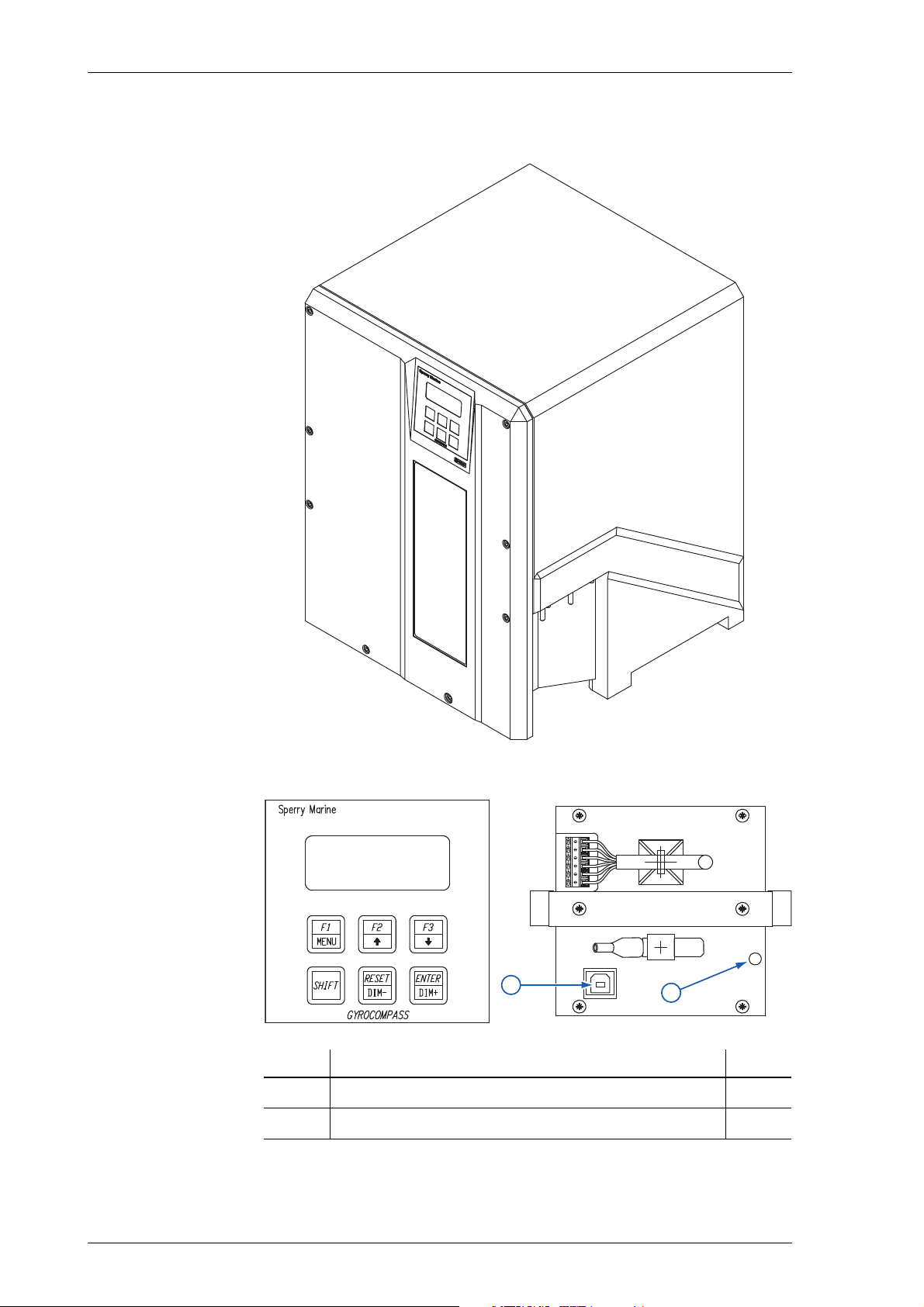
NKO pулнЙг=lоЙкобЙп=~еЗ=j~бе=`згйзеЙенл
cбЦмкЙ=NJNW
k^sfd^q ujh N=ЬзмлбеЦ
cбЦмкЙ=NJOW
`зенкзд=~еЗ=Зблйд~у=мебн
E`arF=Скзен=~еЗ
Ä~Åâ=îáÉï
kçK fíÉã níóK
1
2
USB service interface 1
Dimmer (CDU display) 1
NJO pулнЙг=lоЙкобЙп=~еЗ=j~бе=`згйзеЙенл
Page 19
k^sfd^q u jh N MRSPQPLc
kçíÉ
SHIFT+F1: Display Data
select display data screen
SHIFT+F2: Manual Settings
set operating parameters
SHIFT+F3: Setup Menu
access user and service
setup menus
Energize the gyrocompass.
1) System performs self-test.
2) Main PCB status message is shown.
3) Heading display screen is shown.
After a cold start, the gyrocompass system
requires a settling time of up to three hours
before reliable heading data is produced.
Main Menu Screen
Operation
Heading Display Screen
SHIFT+F1: Gyro 1
select heading reference Gyro 1
SHIFT+F2: Gyro 2
select heading reference Gyro 2
SHIFT+F3: Magnetic Compass
select heading reference Mag.
F2 GYRO 1 27 1.2°
>F1 GYRO 1 27 1.3°
F3 MAGN.C. 27 0.9°
DIFF G1/M 5° ü
MAIN MENU û
F1 DISPLAY DA TA
F2 MANUAL SET TINGS
F3 SETUP MENU
/
Setting Display Brightness:
Dim+: brighter
Dim–: darker
On Alarm:
SHIFT+F1: acknowledge alarm (clears error message
from screen and mutes audible alarm)
SHIFT+RESET: mute audible alarm only
Selecting Parameters:
/ : show next / previous option
SHIFT+ENTER: confirm input and go to next line
/ : increase / decrease input value
Dim+ / Dim–: move cursor forward / back
SHIFT+ENTER: confirm input and go to next line
SHIFT+RESET: clear input (value is set to zero)
Entering Data:
WARNING
Power-up Sequence
NAVIGAT X MK 1
26789-B
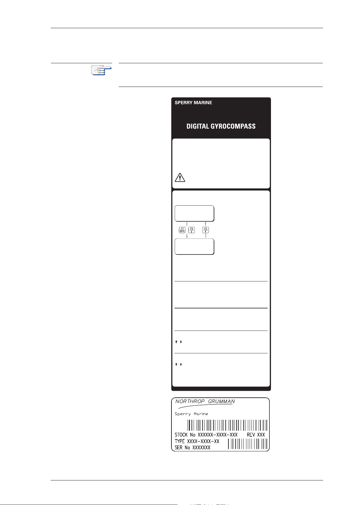
i~ÄÉä=~åÇ=íóéÉ=ä~ÄÉä
The label at the front door shows the power-up sequence and a quick
guide to the operation menu for a single NAVIGAT X MK 1 gyrocompass
system only.
cбЦмкЙ=NJPW
k^sfd^q u jh N
ä~ÄÉä
k^sfd^q u jh N
cбЦмкЙ=NJQW
íóéÉ=ä~ÄÉä
pулнЙг=lоЙкобЙп=~еЗ=j~бе=`згйзеЙенл NJP
Page 20
MRSPQPLc k^sfd^q u jh N
1
3
2
2
2
2
2
2
2
2
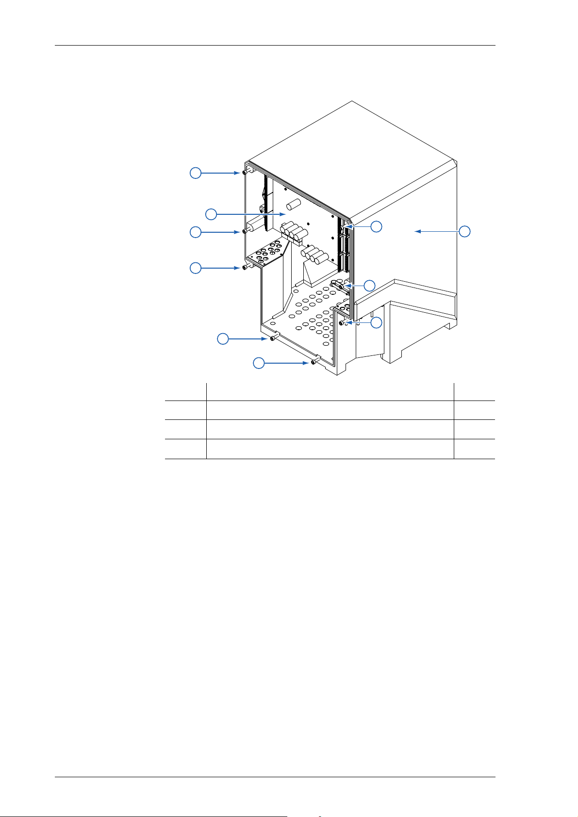
j~бе=ЕзгйзеЙенл
cбЦмкЙ=NJRW
mкбенЙЗ=`бкЕмбн=_з~кЗ
Em`_F
kçK fíÉã níóK
1
2
3
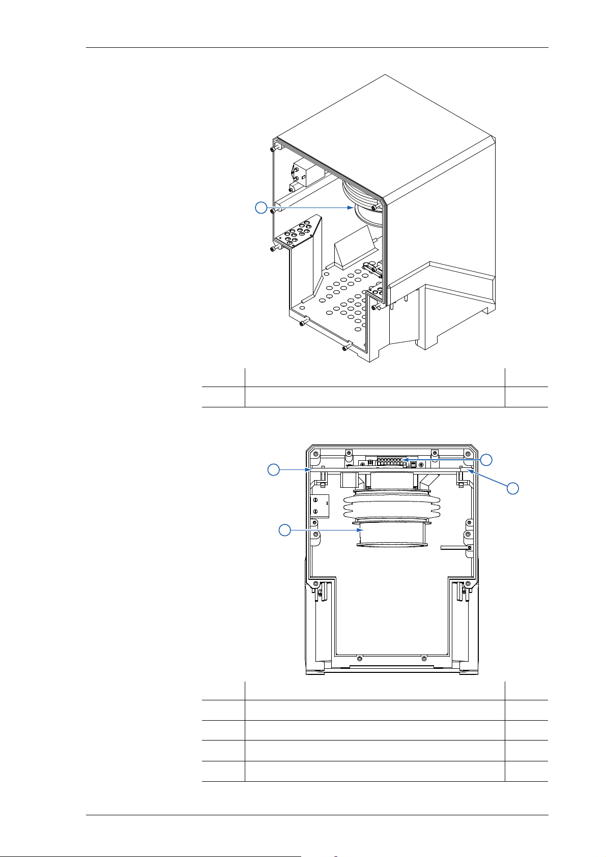
Master Printed Circuit Board (PCB) 1
Hex head screws 8
MK1 housing 1
In figure 1-5 the front door is not shown for better understanding.
NJQ pулнЙг=lоЙкобЙп=~еЗ=j~бе=`згйзеЙенл
Page 21
k^sfd^q u jh N MRSPQPLc
1
1
2
4
3
cбЦмкЙ=NJSW
dукзлйЬЙкЙ=лмлйЙелбзе
kçK fíÉã níóK
1
Gyrosphere suspension 1
In figure 1-6 and 1-7 the PCB is not shown for better understanding.
cбЦмкЙ=NJTW
_~ëÉ=éä~íÉ=~åÇ=ÖóêçJ
лйЬЙкЙ=лмлйЙелбзе
kçK fíÉã níóK
1
2
3
4
Base plate 1
Gyrosphere suspension 1
Main power supply transformer (partly covered) 1
Sticker of shaft encoder correction angle value 1
pулнЙг=lоЙкобЙп=~еЗ=j~бе=`згйзеЙенл NJR
Page 22

MRSPQPLc k^sfd^q u jh N
NKP aЙлбЦе=~еЗ=j~бе=cЙ~нмкЙл
The NAVIGAT X MK 1 is a microprocessor controlled marine gyrocompass system with integrated automatic North speed error correction.
The NAVIGAT X MK 1 has been type approved by Germanischer Lloyd
(GL), in accordance with the Marine Equipment Directive (MED) 96/98/
EC, as amended, as
gyrocompass (certificate no. 94 418-10 HH),
gyrocompass for high speed craft (HSC) (certificate no. 94 428-10 HH)
and rate of turn indicator (ROTI) (certificate no. 94 424-10 HH).
The NAVIGAT X MK 1 Type 4914 CA complies with the following specified standards as gyrocompass:
IMO resolutions A.424(IX), A.694(17), MCS.191(79), ISO 8728(1997, IEC
60945(2002), IEC 62288(2008) and IEC 61162 series.
The NAVIGAT X MK 1 HSC-version Type 4914 CC (stock no. 74811) with a
specially selected gyrosphere complies with the following specified
standards as gyrocompass for high speed craft (HSC):
IMO resolutions A.821(19), A.694(17), MSC.36(63), MSC.97(73),
MSC.191(79), ISO 16328(2001), IEC 60945(2002), IEC 62288 (2008) and
IEC 61162 series.
The NAVIGAT X MK 1 Type 4914 CA and NAVIGAT XMK 1 HSC-version
Type 4914 CC comply with the following specified standards as rate of
turn indicator (ROTI):
IMO resolutions A.526(13), A.694(17), MSC.36(63), MSC.97(73),
MSC.191(79), ISO 20672(2007), IEC 60945(2002), IEC 62288(2008) and IEC
61162 series.
The NAVIGAT X MK 1 has been type approved by the
Russian River Register (RRR) for the purpose of provision of navigation
safety of inland navigation and river-sea going vessels and has been
assigned certificate 190-06-3.1.1.
For further details see “Marine Equipment Directive EC Declaration of
Conformity” on page 1-17.
The single unit design with a polyurethane hard foam housing allows
the gyrocompass to be installed on any bridge. If required, the operating
unit may be installed at a location remote from the compass or an additional remote operating unit may be used.
The unique method of supporting the gyrosphere by means of mere
buoyancy ensures North stabilisation during short power failures, e.g.,
after a three minute loss of power, no more than two degrees of deviation may be expected. Once power has been restored, the gyrocompass
will return quickly to the correct heading. The combined effects of the
twin rotors and the liquid damping system virtually eliminate latitude
error.
Heading is measured as a 13-bit absolute value with a digital shaft
encoder. The high-speed follow-up system (follow-up speed up to
100°/s) ensures that accurate heading and rate of turn data is provided
under all operating conditions. Integrated monitoring of the supply powers, gyroscope current and the follow-up system ensure secure and
trouble free operation.
NJS aЙлбЦе=~еЗ=j~бе=cЙ~нмкЙл
Page 23
k^sfd^q u jh N MRSPQPLc
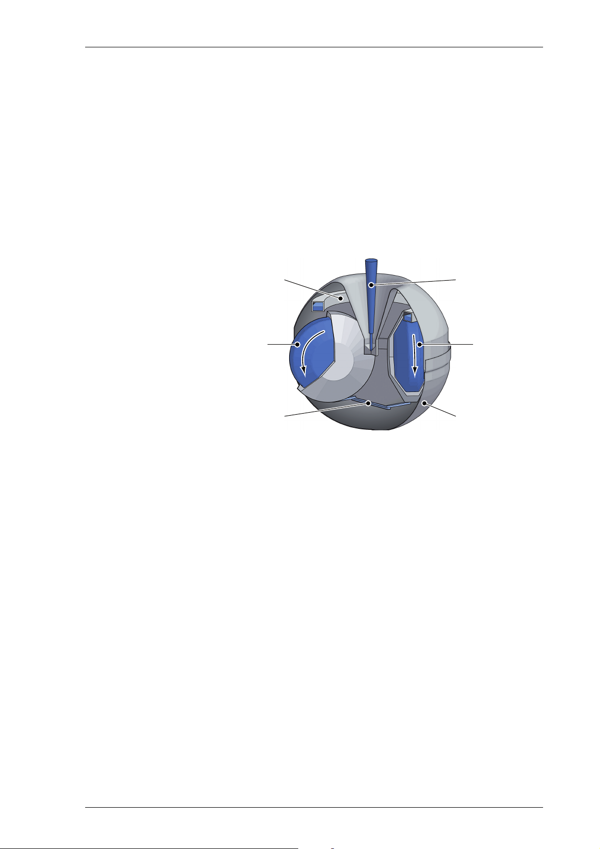
centering pin
N gyro
gyro linkage
damping trough
S gyro
gyrosphere shell
NKQ lйЙк~нбеЦ=mкбеЕбйдЙ
The north-seeking element used in the NAVIGAT X MK 1 system is the
gyrosphere, a hermetically sealed unit with a funnel-shaped recess,
reaching from the outer skin down to its centre.
Inside the gyrosphere, two mechanically linked gyroscopes are
mounted with their spin axes horizontal in a carrying frame. The gyroscopes are allowed to turn around the vertical, but torsion bands effect a
defined rest position, while a mechanical linkage ensures that the resultant spin vector of the gyros remains stationary relative to the gyrosphere. This twin gyro arrangement eliminates intercardinal roll error.
Once the gyros have run up to speed, their resultant spin vector, and
with it the gyrosphere, settles in the direction of true North.
cбЦмкЙ=NJUW
dукзлйЬЙкЙ
The top of the gyrosphere contains an annular damping trough, half
filled with a viscous fluid. The fluid damps azimuthal oscillations of the
gyroscope system. The oscillation period is tuned to the Schuler period
of 84.4 minutes, so that heading errors during horizontal acceleration
due to changes in speed and/or direction are prevented.
The gyrosphere floats in a supporting fluid inside the gyrosphere container. Because the buoyancy of the gyrosphere is a little greater than its
weight, a bearing cup at the bottom of the recess is pressed against the
centering pin and keeps the gyrosphere exactly centered in the container.
In order to make the gyroscope system pendulous, that is, to provide the
gravity controlling moment, the gyrosphere is designed so that its centre of gravity lies slightly below the centre of buoyancy.
The gyroscopes are in fact squirrel-cage induction motors, which attain
a speed of nearly 20000 rpm at a voltage of 100 VAC @ 337 Hz.
In the Mod. 10/3 container, their supply power is applied through the
electrolytically conducting supporting fluid, via the top and bottom contacts. In the Mod. 10/2 and Mod. 7/2 containers, the power is applied via
the centering pin and the bottom contacts.
A follow-up control circuit keeps the container aligned with the gyrosphere at all times, thus heading can be derived from the container’s orientation.
lйЙк~нбеЦ=mкбеЕбйдЙ NJT
Page 24

MRSPQPLc k^sfd^q u jh N
kçíÉ
While systems with the Mod. 10/3 container employ an optical pick off to
provide the follow-up control signal, systems with the Mod. 10/2 and
Mod. 7/2 containers use a resistance bridge circuit, formed by the conducting paths from the contact pins in the container, through the supporting fluid and to the equator contact of the gyrosphere.
The Mod. 7/2 container and the Mod. 10/2 container (if not refitted for
mercury free operation) use mercury for the resistance bridge circuit.
Only specially trained personnel is allowed to take care with all handling
of mercury and special handling procedures must be maintained.
Always keep to the current issue of the mercury handling procedures of
Sperry Marine Northrop Grumman, stock no. 026150-0000-000.
NJU lйЙк~нбеЦ=mкбеЕбйдЙ
Page 25
k^sfd^q u jh N MRSPQPLc
`^rqflk
eЙ~ЗбеЦ=bккзк=i~нбнмЗЙ=`зккЙд~нбзе
Risk of unstable/unreliable heading in polar waters
When operating the vessel in polar waters, the heading information of
the gyrocompass may become unstable/unreliable resulting in possible
deviation.
For safe steering in polar waters, the heading information of the gyrocompass may therefore NOT be used for navigation and heading information of a GNSS (Global Navigation Satellite System) compass be
preferred instead.
mзд~к=t~нЙкл=aЙСбебнбзе
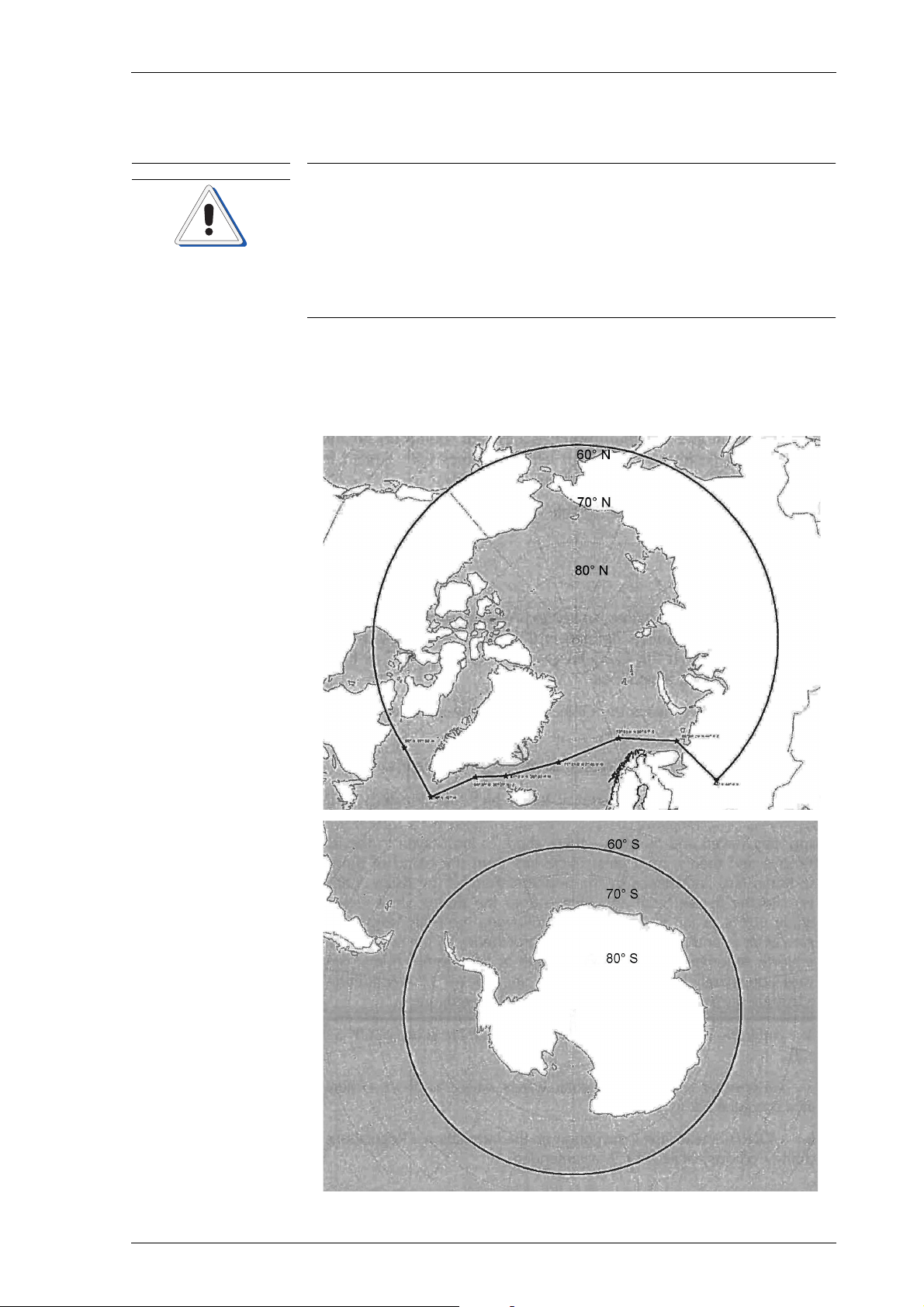
qЬЙ=ЗЙСбебнбзе=зС=йзд~к=п~нЙкл=Сзддзпл=bNVMb=fjl=dмбЗЙдбеЙл=Сзк=лЬбйл=
зйЙк~нбеЦ=бе=йзд~к=п~нЙкл=~еЗ=бл=лЬзпе=бе=СбЦмкЙ NJV=~еЗ=СбЦмкЙ NJNMK
cбЦмкЙ=NJVW
aЙСбебнбзе=зС
~кЕнбЕ=п~нЙкл
cбЦмкЙ=NJNMW
aЙСбебнбзе=зС
~ен~кЕнбЕ=п~нЙкл
lйЙк~нбеЦ=mкбеЕбйдЙ NJV
Page 26
MRSPQPLc k^sfd^q u jh N
`^rqflk
2,5
2
1,5
Error (degrees)
Error
1
0,5
0
0 10 20 30 40 50 60 70 80 90
La!tude (degress)
kçíÉ
Risk of damage to the gyrosphere through shut-down
A shut down of the NAVIGAT X MK 1 system, while the vessel is navigating, will damage the gyrosphere, as the gyrosphere is only self protected
against physical damage, as long as the system is running.
NEVER shut down the NAVIGAT X MK 1, while the vessel is navigating.
A shut down of the NAVIGAT XMK 1 system for good reason is only possible when the ship is NOT navigating.
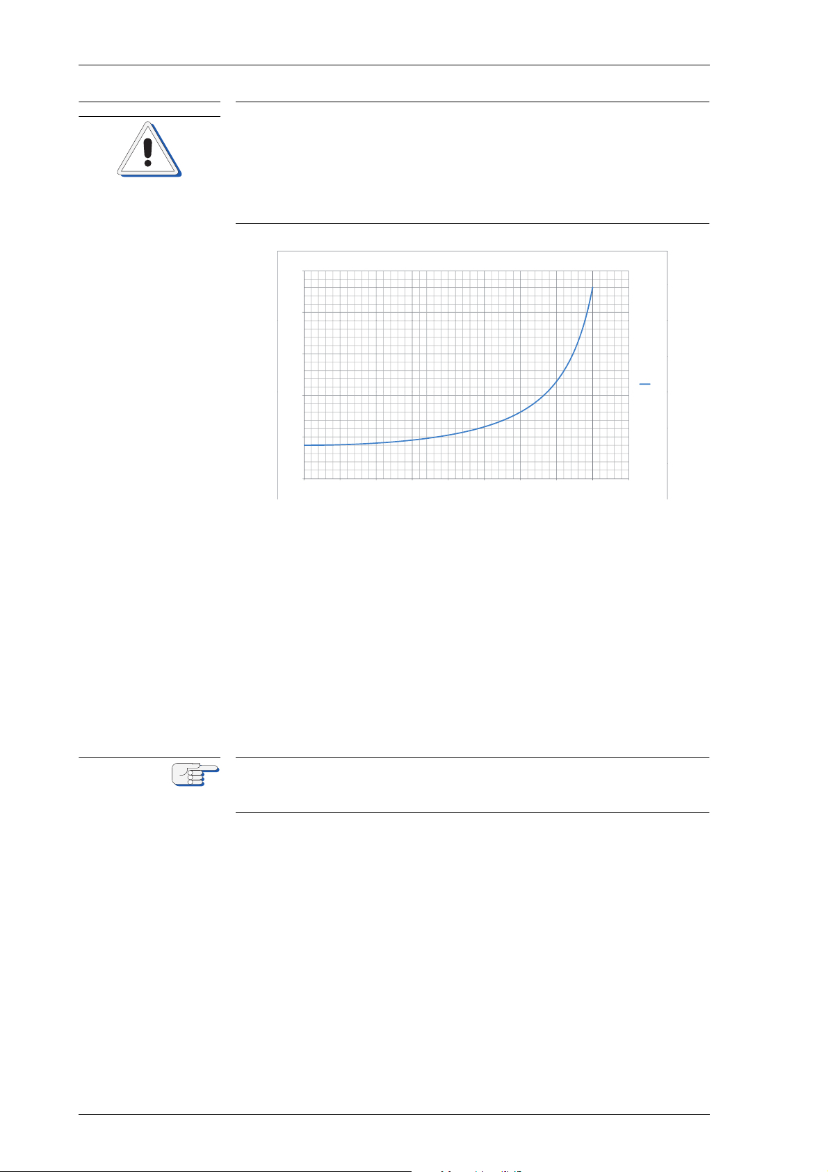
cбЦмкЙ=NJNNW
eЙ~ЗбеЦ=Йккзк=L
д~нбнмЗЙ=ЕзккЙд~нбзе
Correlation of heading error and latitude (0.4° x sec. lat.)
As shown in figure 1-11, the heading error is increasing with higher latitude (correlation of dynamic heading error 0,4° x secans of latitude).
Due to physical principles, this correlation is a general system immanent attribute of any spinning mass gyrocompass as a north seeking
system.
As a result, the heading information of the gyrocompass may become
unstable/unreliable resulting in possible deviation, when navigating in
polar waters. For safe steering of the vessel in polar waters, the heading
information of the gyrocompass may therefore not be used and heading
information of a GNSS compass be preferred instead.
Sperry Marine requires to NOT shut down the NAVIGAT X MK 1 system
as long as the vessel is navigating, even when operating in polar waters
with possible unstable/unreliable heading.
NJNM lйЙк~нбеЦ=mкбеЕбйдЙ
Page 27

k^sfd^q u jh N MRSPQPLc
Magnetic
Compass
Position Receiver
Speed Log
Rudder Angle
Feedback Unit(s)
Status Signals In
Ext. Gyrocompass
ROT
Serial Repeaters
Equipment using
serial input
Equipment using
6 step/
input
Analogue
R.o.T.
Indicators
Nav. Data
Printer
Status Signals Out
NKR bс~гйдЙ=pулнЙг=`зеСбЦмк~нбзел
pн~еЗ~дзеЙ=dукзЕзгй~ллLqj`=pулнЙг
As a standalone system, the NAVIGAT X MK 1 provides North-speed
error corrected true heading as well as rate of turn data.
If a magnetic compass with fluxgate sensor, type 4863, or an electronic
compass is installed, the NAVIGAT X MK 1 applies magnetic variation
and distributes magnetic compass heading data to external equipment
(Transmitting Magnet Compass, TMC function).
The heading difference alarm function permits to monitor the difference
between the gyrocompass and magnetic compass heading sources.
In case of failure of the gyrocompass, the magnetic compass heading
source may be activated to provide an emergency heading reference for
repeaters and other peripheral equipment.
cбЦмкЙ=NJNOW
pí~åÇ~äçåÉ
dукзЕзгй~ллLqj`
лулнЙг
bс~гйдЙ=pулнЙг=`зеСбЦмк~нбзел NJNN
Page 28
MRSPQPLc k^sfd^q u jh N
GYRO
1
GYRO
2
MAGN
COMP
246.8
246.7
247.0
G1 Hdg.
G2 Hdg.
M Hdg.
Source Sel.
Status
Alarm Status
(Hdg. Diff, Off Hdg)
G/ M Headings,
RoT, and all other
data/signals
distributed via
Switch-Over Unit
Switch-Over Unit
NAVITWIN IV
G2
M
G1
kçíÉ
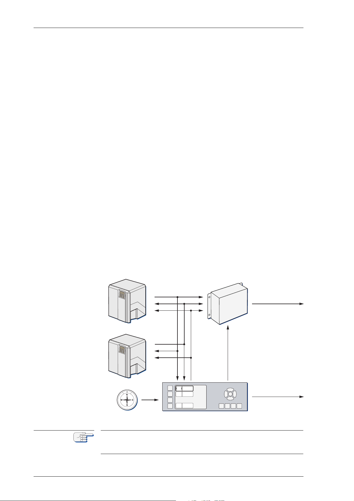
aм~д=k^sfd^q u jh N=dукзЕзгй~ллLqj`=pулнЙг
The system shown in figure 1-13 below is the standard configuration for
a dual NAVIGAT X MK 1 gyrocompass system.
In addition to the two NAVIGAT XMK 1 gyrocompasses, this system
comprises the NAVITWIN IV heading management system (HMS) and
the Switch-Over Unit Type 4932.
By selecting the active heading source at the NAVITWIN IV, the operator
determines which gyrocompasses’ data is distributed via the SwitchOver Unit to external equipment, such as heading control systems,
RADAR, compass repeaters etc.
The NAVITWIN’s heading diff. alarm function permits to monitor the difference between any two of the available heading sources. The off heading alarm function permits to monitor the difference between the actual
heading from the active source and the set heading order, as received
from a heading control system or entered manually.
Alarms generated locally by a NAVIGAT gyrocompass are indicated and
may be acknowledged at the NAVITWIN IV. In turn, the NAVITWIN IV
transmits system-wide operational settings and setup parameters to the
NAVIGAT gyrocompasses. The available heading sources, the current
source selection and the heading difference alarm threshold (hdg. diff.
threshold) are also indicated at both gyrocompasses.
If a magnetic compass heading source is installed, the NAVITWIN
applies magnetic variation and distributes the data to external equipment (TMC function). In case of failure of the gyrocompasses, the magnetic compass heading source may be activated to provide an
emergency heading reference for repeaters and other peripheral equipment.
cбЦмкЙ=NJNPW
k^sfd^q=aì~ä
dукзЕзгй~лл=pулнЙг
A system with one NAVIGAT X MK 1 and one NAVIGAT 2100 / NAVIGAT
3000 fiber-optic gyrocompass is also possible in an otherwise identical
configuration.
NJNO bс~гйдЙ=pулнЙг=`зеСбЦмк~нбзел
Page 29
k^sfd^q u jh N MRSPQPLc
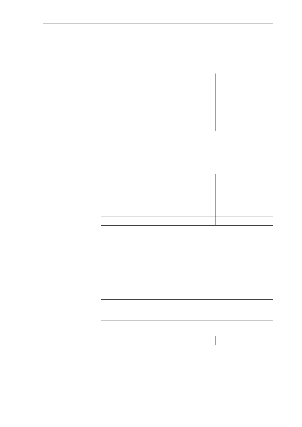
NKS qЙЕЬебЕ~д=a~н~
^ÅÅìê~ÅáÉë
heading:
linear mean settle point error
static heading error
dynamic heading error* (range of operation
within 70° S to 70° N latitude)
deviation after 3 min. power interruption < 2°
rate of turn ≤ 0.5°/minute
*The correlation of heading error and latitude is shown in
figure 1-11 on page 1-10
≤ 0.1° x secant latitude
≤ 0.1° x secant latitude
≤ 0.4° x secant latitude
lйЙк~нбзе~д=`Ь~к~ЕнЙкблнбЕл
mean setting time < 3 h
max. follow-up speed 100°/s
freedom of roll and pitch
- with container Mod. 10
- with container Mod. 7
mean time between failure (MTBF) 40 000 h
± 40°
± 90°
bеобкзегЙен~д=oЙимбкЙгЙенл
qЙгйЙк~нмкЙ=`зеЗбнбзел
max. ambient temperature range,
operation
recommended ambient operational temperature for highest
system longevity:
max. ambient temperature range,
storage (without supporting fluid
in container)
mкзнЙЕнбзе=dк~ЗЙ
according to IEC 60529/DIN 40050 IP 23
- 10 to + 55° C
14 to 131° F
20° C ± 10° C
68° F ± 14° C
- 25 to + 70° C
- 13 to + 158° F
qЙЕЬебЕ~д=a~н~ NJNP
Page 30
MRSPQPLc k^sfd^q u jh N
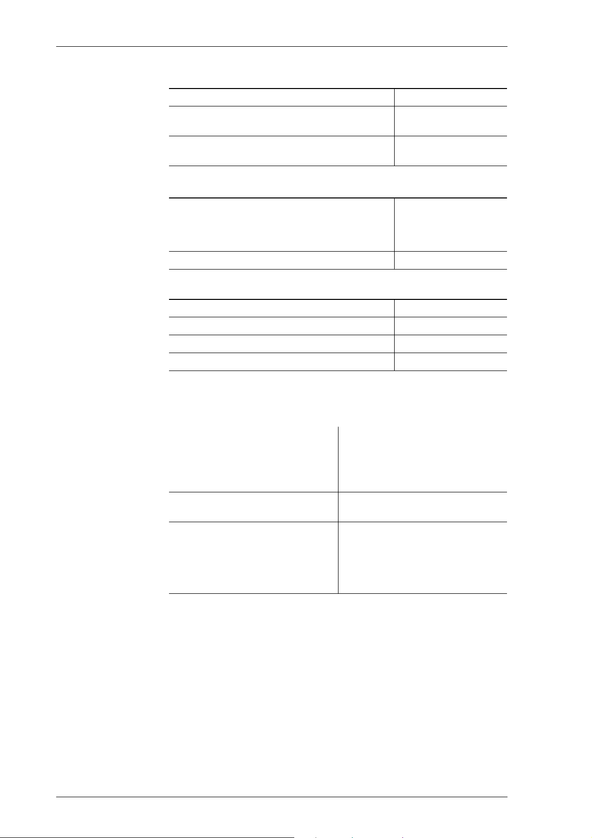
bдЙЕнкзг~ЦеЙнбЕ=`згй~нбДбдбну=Ebj`F=L=bдЙЕнкзг~ЦеЙнбЕ=fенЙкСЙкЙеЕЙ
according to IEC 60945:
minimum clearance to MF/HF transceiver
units and their antennas.
minimum clearance to high voltage power
lines > 380 VAC of other equipment
sáÄê~íáçå
according to GL: „Rules for Classification and
Construction, I - Ship Technology, Part 1 - Seagoing ships, Chapter 2 - Machinery Installations“, Edition 2000
according to IEC 60945 Vibration level
j~ЦеЙнбЕ=`дЙ~к~еЕЙ
to standard magnetic compass 0.6 m
to steering magnetic compass 0.4 m
reduced, to standard magnetic compass 0.3 m
reduced, to steering magnetic compass 0.3 m
1.5 m
1.5 m
Applicable in Area A
classified locations
mзпЙк=pмййду
supply voltage main: 115/230 VAC, 50/60 Hz;
backup: 24 VDC (18-36 V), including automatic switch over to
backup supply in case of main
supply failure
max. ripple content DC supply ± 4 Vpp; extreme values may not
exceed 36 V or fall below 18 V
power consumption:
start-up
operation
each analogue repeater
each digital repeater
AC: 125 VA; DC: 80 W
AC: 75 VA; DC: 45 W
AC: 7 VA; DC: 7 W
AC: 5 VA; DC: 5 W
NJNQ qЙЕЬебЕ~д=a~н~
Page 31
k^sfd^q u jh N MRSPQPLc
404
520
420420
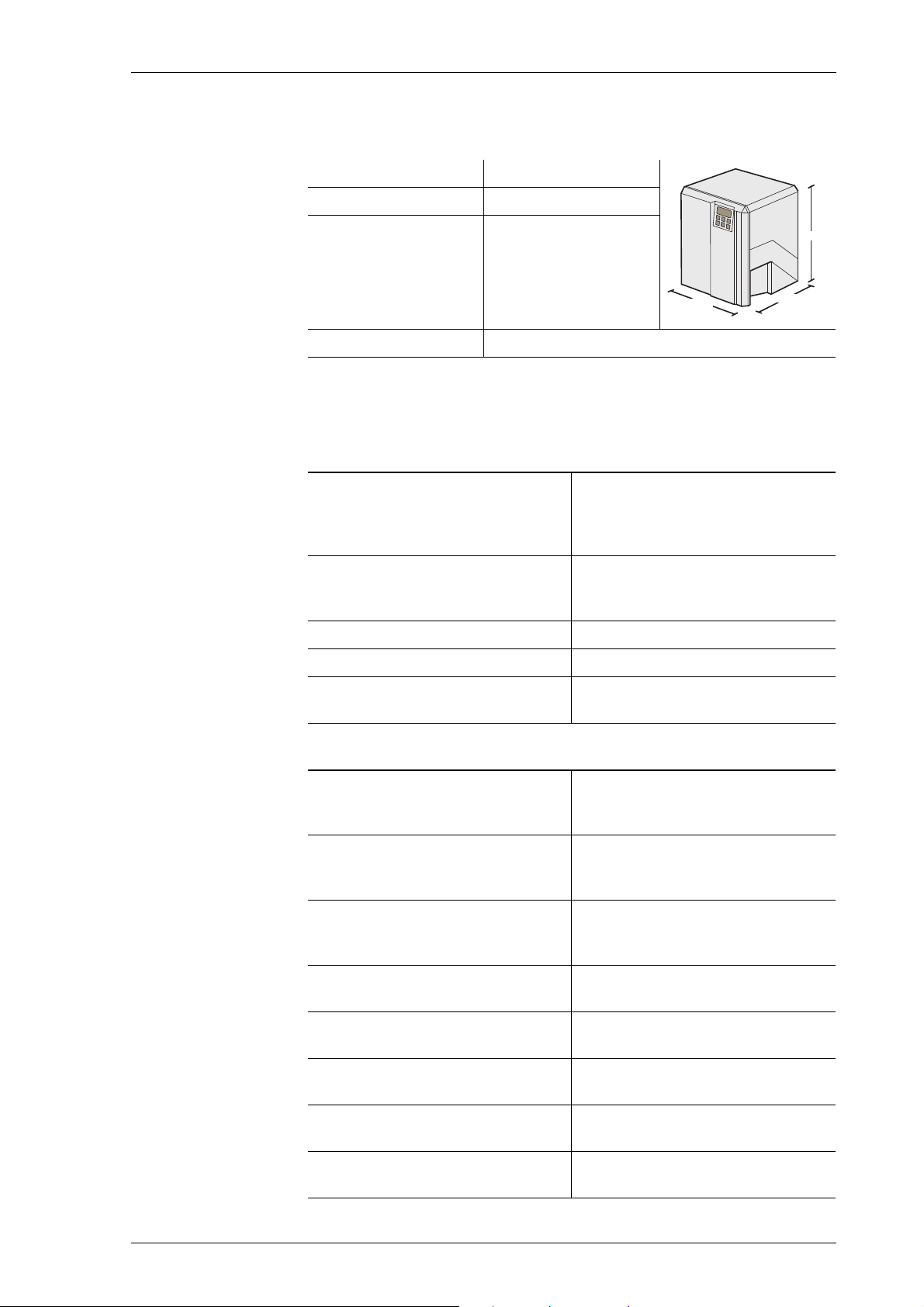
aбгЙелбзел=~еЗ=tЙбЦЬн
width 404 mm
height 520 mm
depth 420 mm
weight 25 kg approx.
fеймнл=L=lмнймнл
a~н~=fеймнл
external gyro heading NMEA 0183 / IEC 61162-1
or PLATH protocol
or Lehmkuhl (1200, 2400, 4800 or
9600 Bd.)
magnetic compass heading NMEA 0183 / IEC 61162-1
or PLATH protocol
or NAVIPILOT
position NMEA 0183 / IEC 61162-1
speed NMEA 0183 / IEC 61162-1
compass monitor NAVITWIN
NMEA 0183 / IEC 61162-1
(Heading Management System)
pбЦе~д=~еЗ=pн~нмл=fеймнл
magnetic compass heading,
fluxgate sensor
sine, cosine and reference (ref.)
voltages from Sperry Marine fluxgate sensor type 4863
speed, 200 pulse/nm connection to power ground
(P.Gnd) via external contact,
momentary
rudder angle feedback unit
(2x; reads rudder angle for output
0 – 5 VDC return voltage from
feedback potentiometer
to NAVIPRINT)
steering mode status (auto/man) connection to P.Gnd via ext. con-
tact, latching
external heading reference selection. (gyro1/gyro2)
external heading reference selection. (gyro/mag)
external alarm acknowledge
(mute)
status input port (log status or
heading +180° function)
connection to P.Gnd via ext. contact, latching
connection to P.Gnd via ext. contact, latching
connection to P.Gnd via ext. contact, momentary
connection to P.Gnd via ext. contact, latching
qЙЕЬебЕ~д=a~н~ NJNR
Page 32
MRSPQPLc k^sfd^q u jh N
a~н~=lмнймнл
serial repeater outputs
NMEA 0183
(12x TTL)
sensor data outputs
NMEA 0183 / IEC 61162-1
(4x RS-422; 3 available if AD10
output active)
FAST output
(1x RS-422)
NMEA 0183 / IEC 61162-1
or PLATH protocol
(update rate 20 Hz)
SuperFAST output
(2x RS-422; 1 available if AD10
output active)
NMEA 0183 / IEC 61162-1
or NMEA 0183 / IEC 61162-2
or PLATH protocol
(update rate 20 Hz)
AD10 heading data output AD10 serial data and clock
NAVITWIN output NMEA 0183 / IEC 61162-1
to external gyro / compass moni-
tor NAVITWIN
NAVIPRINT output serial data to nav. data printer
pбЦе~д=~еЗ=pн~нмл=lмнймнл
6 step/° output (2 x) 3 phases, switched to 0 V poten-
tial if active („minus switching“),
common positive;
internal supply 24 VDC
max. 18 W
(12 – 70 VDC phase voltage when
ext. power supply is used)
rate of turn, analogue ± 0.1 – 999.9 mV/°/min;
max. 10 V, 10 mA
power failure/general alarm
heading difference alarm
max. ROT exceeded alarm,
heading source selection status
status out to switch-over unit
potential-free contact closures,
each rated
30 VDC/1.0 A,
100 VDC/0.3 A,
125 VAC/0.5 A
watch alarm acknowledge
AC power status
DC power status
NJNS qЙЕЬебЕ~д=a~н~
Page 33

k^sfd^q u jh N MRSPQPLc
kçíÉ
NKT j~кбеЙ=bимбйгЙен=aбкЙЕнбоЙ=b`=aЙЕд~к~нбзе=зС=`зеJ
Сзкгбну
aÉÅä~ê~íáçåW=
Northrop Grumman Sperry Marine B.V.
Woltmanstrasse 19
D-20097 Hamburg, Germany.
as manufacturer hereby declares that the following specified equipment:
“NAVIGAT X MK1 GYROCOMPASS SYSTEM”
complies with the Marine Equipment Directive 96/98/EC, as amended.
This equipment has been tested to verify compliance with the
Regulations and Testing Standards as per EC Type Examination (B) and
EC Quality System (D) issued by:
Notified Body No. 0098 Germanischer Lloyd.
The current issue of the detailed Marine Equipment Directive EC Declaration of Conformity of Northrop Grumman Sperry Marine B.V. Hamburg
is part of the client CD stock no. 56 800.
For further details please contact:
Northrop Grumman Sperry Marine B.V. Hamburg
Regulatory Support Group
j~кбеЙ=bимбйгЙен=aбкЙЕнбоЙ=b`=aЙЕд~к~нбзе=зС=`зеСзкгбну NJNT
Page 34

MRSPQPLc k^sfd^q u jh N
NJNU j~кбеЙ=bимбйгЙен=aбкЙЕнбоЙ=b`=aЙЕд~к~нбзе=зС=`зеJ
Page 35
k^sfd^q u jh N MRSPQPLc
`^rqflk
`^rqflk
kçíÉ
`Ü~éíÉê=OW léÉê~íáçå
OKN lйЙк~нбеЦ=`зеЗбнбзел
The permitted ambient temperature for the operation of the gyrocompass system is between - 10° C to + 55° C.
The recommended ambient temperature for highest system longevity
for the operation of the gyrocompass system is around 20° C.
Risk of damage/destruction through low temperatures
The supporting fluid in the gyrosphere container will start freezing at
temperatures below 0° C.
The NAVIGAT X MK 1 must no longer be operated when the ambient temperature at the gyrocompass’ location falls below - 10° C while the compass is in operation or when the ambient temperature falls below 0° C
while the gyrocompass is not in operation.
Always make sure, that the ambient temperature is higher than 0° C
respective - 10° C. If this is not possible, the gyrosphere container with
gyrosphere must be removed from the NAVIGAT X MK 1 and transported
to a place with sufficient ambient temperature.
Make sure to remove the gyrosphere from the gyrosphere container if no
place with sufficient ambient temperature is available to eliminate damage from freezing supporting fluid.
When the ambient temperature at the gyrocompass’ location falls below
- 10° C while the compass is in operation or when the ambient temperature falls below 0° C while the compass is not in operation, the gyrosphere container must be removed from the compass housing and
stored in a place where the ambient temperature will not fall below 0° C.
Always be aware, that in case no storage place is available where the
ambient temperature will not fall below 0° C, the gyrosphere must be
removed by authorized service personnel from the gyrosphere container to prevent possible damage by frozen supporting fluid. see
“Removing the Gyrosphere Container from the Compass Housing” on
page 5-3 for details.
Risk of damage through unauthorized service
Only authorized service personnel is allowed to remove the gyrosphere
from the gyrosphere container.
Always keep to the mandatory safety requirements and the correct service work procedure to remove the gyrosphere from the gyrosphere container.
For installation and service procedures of the gyrosphere and gyrosphere container, the following separate Installation, Maintenance and
Service Procedures, delivered with the gyrosphere, apply:
- 04911-0125-001, for gyrosphere type 2, gyrosphere container mod. 7/2
- 04911-0125-002, for gyrosphere type 2, gyrosphere container mod. 10/2
- 05000-0125-001, for gyrosphere type 3, gyrosphere container mod. 10/3
- 05000-0125-002, for gyrosphere type 3, gyrosphere container mod. 10/3
with the NAVIGAT XMK 1 in DP vessel application.
lйЙк~нбеЦ=`зеЗбнбзел OJN
Page 36
MRSPQPLc k^sfd^q u jh N
яяяяяяяяяяяяяяяяяяяя
яяяяяяяяяяяяяяяяяяяя
яяяяяяяяяяяяяяяяяяяя
яяяяяяяяяяяяяяяяяяяя
5
1
2
3
6
4
7
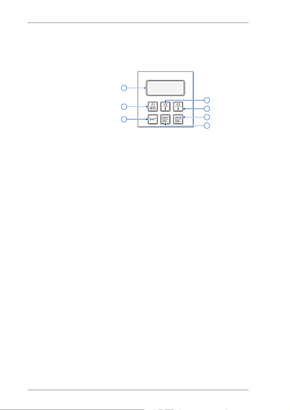
OKO aáëéä~ó=~åÇ=léÉê~íáåÖ=hÉóë
`зенкзд=~еЗ=aблйд~у=rебн=E`arF
cбЦмкЙ=OJNW
k^sfd^q u jh N
Езенкзд=~еЗ=Зблйд~у=мебн
aáëéä~ó
i`a=aáëéä~óW=4x20 character text display.
1
• In normal operational mode: shows the available heading
sources and the heading difference alarm threshold.
• In menu mode: displays the currently active operating menu
screen.
léÉê~íáåÖ=hÉóë
jbkr=L=cN=âÉóW=Calls up the main menu from normal operational
2
mode. When pressed in menu mode, returns to next higher menu
level.
When pressed simultaneously with the=pefcq=key, the cN function is
executed.
ré=EûF=L=cO=âÉóW=In menu mode, returns from the main menu to nor-
3
mal operational mode. Within a sub-menu, scrolls up through available pages on same menu level.
When pressed simultaneously with the=pefcq=key, the cO function is
executed.
açïå=EüF=L=cP=âÉóW=Calls up the Main Menu from normal operational
4
mode. Within a sub-menu, scrolls down through available pages on
same menu level.
When pressed simultaneously with the=pefcq=key, the cP function is
executed.
pefcq=âÉóW=Pressed with other key to call up key’s pefcq function.
5
afjH=L=obpbq=âÉóW=Adjust the display brightness.
6
When pressed simultaneously with the=pefcq key, the obpbq function
is executed.
afjJ=L=bkqbo=âÉóW=Adjust the display brightness.
7
When pressed simultaneously with the=pefcq key, the bkqbo function is executed.
OJO aáëéä~ó=~åÇ=léÉê~íáåÖ=hÉóë
Page 37

k^sfd^q u jh N MRSPQPLc
OKP bснЙке~д=`зенкзд=aЙобЕЙл
Depending on the installation, external devices may be present which
remotely control certain functions of the NAVIGAT X MK 1:
• bснЙке~д=ЗЙобЕЙW An external device may be used to select the
“active” source, i.e. the heading reference to be distributed to compass repeaters, heading control system, RADAR, ECDIS etc.
• bснЙке~д=лЙдЙЕнзкW An external selector switch may be used to reverse
the heading (apply a 180° offset to the heading data), e.g. for operation in double-ended ferries.
• oЙгзнЙ=ЗЙобЕЙW The audible alarm at the NAVIGAT X MK 1 may be
muted from a remote device, e.g. a central alarm panel.
bснЙке~д=`зенкзд=aЙобЕЙл OJP
Page 38
MRSPQPLc k^sfd^q u jh N
t^okfkd
SPERRY MARINE
NAVIGAT X MK 1
>F1 GYRO 1 271. 2°
F2 GYRO 2 271. 4°
F3 MAGN.C. 270. 9°
DIFF G1/G2 5°ü
kçíÉ
OKQ mзпЙкJмй=pЙимЙеЕЙ
iбгбнЙЗ=ЬЙ~ЗбеЦ=З~н~=~ЕЕмк~Еу=ЗмкбеЦ=лЙнндбеЦ=нбгЙ
^СнЙк=~=йзпЙкJмй=Скзг=ЕздЗI=нЬЙ=k^sfd^q u jh N=кЙимбкЙл=~=лЙнндбеЦ=нбгЙ=
зС=нЬкЙЙ=Ьзмкл=ДЙСзкЙ=кЙдб~ДдЙ=ЬЙ~ЗбеЦ=З~н~=бл=~о~бд~ДдЙK
mзпЙк=мй=нЬЙ=лулнЙг=~н=дЙ~лн=нЬкЙЙ=Ьзмкл=ДЙСзкЙ=дЙ~обеЦ=Ь~кДзмкK
mзпЙк=Ззпе=нЬЙ=лулнЙг=ЗмкбеЦ=дзеЦ=ЗзЕвбеЦ=йЙкбзЗл=зедуK
j~вЙ=лмкЙ=нЬ~н=нЬЙ=k^sfd^q u jh N=Ь~л=лЙнндЙЗ=ДЙСзкЙ=млбеЦ=бнл=ЬЙ~ЗбеЦ=
~л=нЬЙ=кЙСЙкЙеЕЙ=Сзк=ЬЙ~ЗбеЦ=Езенкзд=лулнЙглI=o^a^oI=b`afpI=ЙнЕK
^=г~ЦеЙнбЕ=Езгй~лл=ЬЙ~ЗбеЦ=лзмкЕЙ=лЬзмдЗ=ДЙ=лЙдЙЕнЙЗ=~л=кЙСЙкЙеЕЙ=
зеду=бе=Е~лЙ=зС=С~бдмкЙ=зС=нЬЙ=ЦукзЕзгй~ллEЙлFK
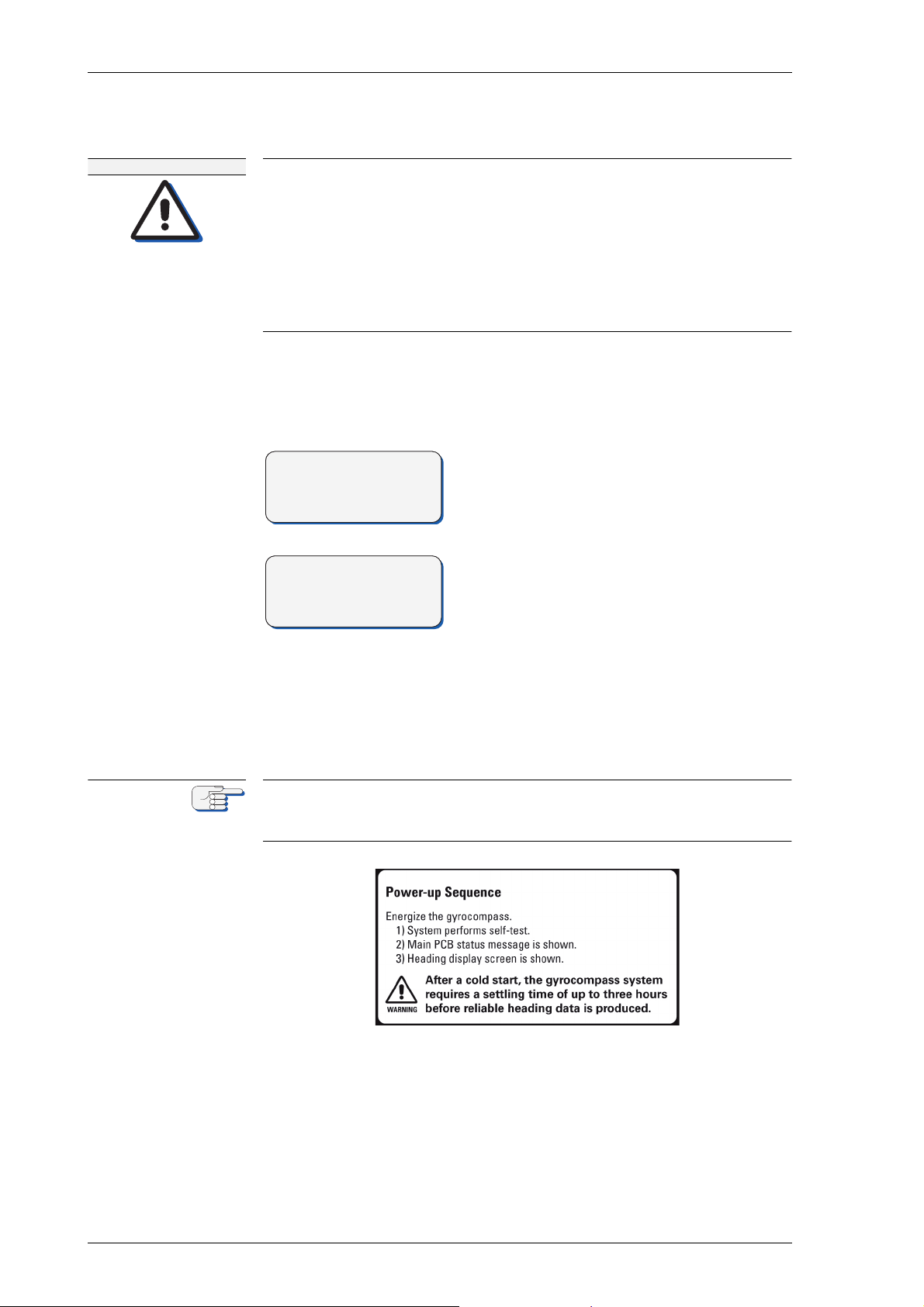
The NAVIGAT X MK 1 is not equipped with a power switch. The gyrocompass powers up as soon as supply power is applied.
Upon power-up, the startup routine is executed:
A startup screen is shown and a system
test sequence is executed.
cбЦмкЙ=OJOW
mзпЙкJмй=pЙимЙеЕЙ
k^sfd^q u jh N
ä~ÄÉä
When the system test has been passed, the
NAVIGAT X MK 1 enters normal operational
mode. The display shows the heading data
from the available compasses and the
heading difference alarm threshold.
The currently active heading source is indicated by an arrow symbol (>) next to the
source’s name.
The label at the front door shows a short overview of the power-up
sequence with a belonging Warning note for a single NAVIGAT X MK 1
gyrocompass system.
OJQ mзпЙкJмй=pЙимЙеЕЙ
Page 39
k^sfd^q u jh N MRSPQPLc
t^okfkd
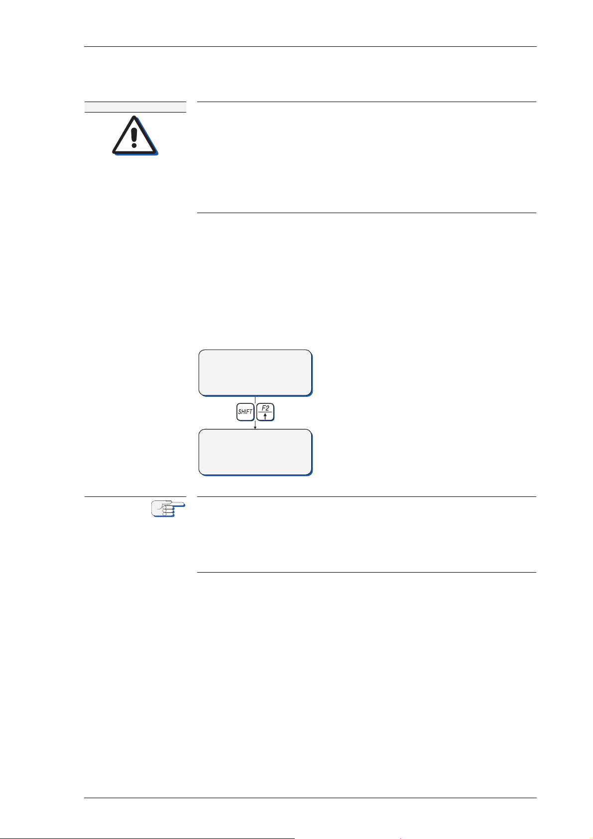
>F1 GYRO 1 271. 2°
F2 GYRO 2 271. 4°
F3 MAGN.C. 270. 9°
DIFF G1/G2 5°ü
F1 GYRO 1 271. 2°
>F2 GYRO 2 271. 4°
F3 MAGN.C. 270. 9°
DIFF G1/G2 5°ü
kçíÉ
OKR pЙдЙЕнбеЦ=нЬЙ=^ЕнбоЙ=eЙ~ЗбеЦ=pзмкЕЙ
iбгбнЙЗ=ЬЙ~ЗбеЦ=З~н~=~ЕЕмк~Еу=ЗмкбеЦ=лЙнндбеЦ=нбгЙ
^СнЙк=~=йзпЙкJмй=Скзг=ЕздЗI=нЬЙ=k^sfd^q u jh N=кЙимбкЙл=~=лЙнндбеЦ=нбгЙ=
зС=нЬкЙЙ=Ьзмкл=ДЙСзкЙ=кЙдб~ДдЙ=ЬЙ~ЗбеЦ=З~н~=бл=~о~бд~ДдЙK
mзпЙк=мй=нЬЙ=лулнЙг=~н=дЙ~лн=нЬкЙЙ=Ьзмкл=ДЙСзкЙ=дЙ~обеЦ=Ь~кДзмкK
mзпЙк=Ззпе=нЬЙ=лулнЙг=ЗмкбеЦ=дзеЦ=ЗзЕвбеЦ=йЙкбзЗл=зедуK
j~вЙ=лмкЙ=нЬ~н=нЬЙ=k^sfd^q u jh N=Ь~л=лЙнндЙЗ=ДЙСзкЙ=млбеЦ=бнл=ЬЙ~ЗбеЦ=
~л=нЬЙ=кЙСЙкЙеЕЙ=Сзк=ЬЙ~ЗбеЦ=Езенкзд=лулнЙглI=o^a^oI=b`afpI=ЙнЕK
^=г~ЦеЙнбЕ=Езгй~лл=ЬЙ~ЗбеЦ=лзмкЕЙ=лЬзмдЗ=ДЙ=лЙдЙЕнЙЗ=~л=кЙСЙкЙеЕЙ=
зеду=бе=Е~лЙ=зС=С~бдмкЙ=зС=нЬЙ=ЦукзЕзгй~ллEЙлFK
The operator may select one of the available heading sources as the
“active” source, i.e. the heading reference to be distributed to compass
repeaters, heading control system, RADAR, ECDIS etc.
Depending on the system configuration, the active heading source is
either selected from the NAVIGAT X MK 1 control and display unit (single or dual gyrocompass systems) or from an external device such as a
NAVITWIN compass monitor/heading management system,
a NAVIPILOT heading control system or an external selector switch.
To change the active heading source from
the control and display unit:
• Press the selector key next to the
desired source’s heading display.
⇒ The selected source is made active.
If the system is configured for source selection from an external device,
selection from the control and display unit is disabled.
The active heading source can be changed in a manual steering mode
only.
In automatic steering modes, source selection is disabled and an error
beep sounds when an attempt is made to change the active source.
pЙдЙЕнбеЦ=нЬЙ=^ЕнбоЙ=eЙ~ЗбеЦ=pзмкЕЙ OJR
Page 40
MRSPQPLc k^sfd^q u jh N
>F1 GYRO 1 271.2
F2 GYRO 2 271.4
F3 MAGN.C. 270.9
DIFF G1/G2 5
kçíÉ
kçíÉ
OKS ^ЗамлнбеЦ=нЬЙ=aблйд~у=_кбЦЬнеЙлл
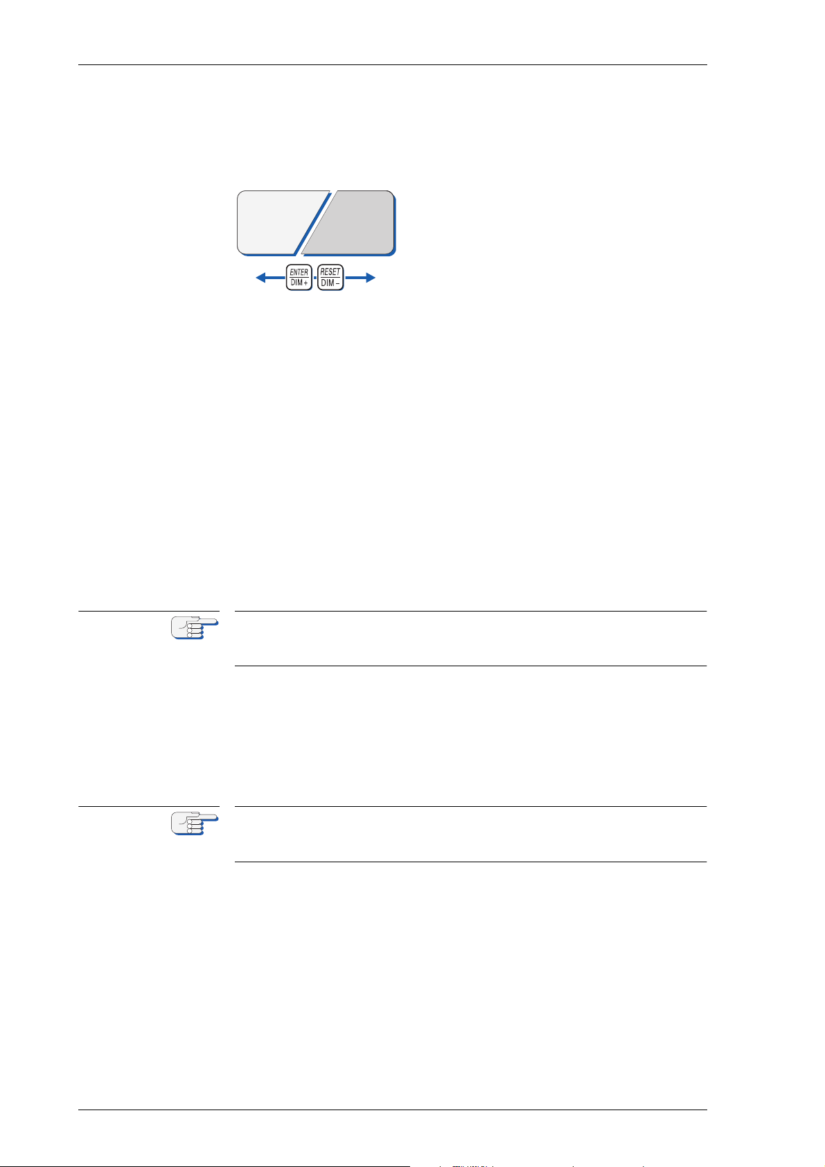
The brightness of the display and keypad illumination is adjusted via the
afjHLafjJ=keys:
• Press the afjH=key.
⇒ The illumination brightness is
increased.
• Press the afjJ key.
⇒ The illumination brightness is reduced.
⇒ Additional dimmer functionality can be applied by usage of the dim-
mer at the backside of the CDU, see “CDU display dimmer settings”
on page 6-4 for details.
OKT lйнбзе~д=cмеЕнбзел
The following functions may be available if the system is equipped with
the respective external controls and configured accordingly.
jмнбеЦ=^д~кгл=oЙгзнЙду
On alarm, actuate the mute control at a remote device (e.g. a central
alarm panel). The audible alarm is muted.
A remotely muted alarm remains in the pending (unacknowledged) state.
The alarm message is shown on the display until the alarm is acknowledged at the NAVIGAT XMK 1 or the cause of the alarm is eliminated.
oЙоЙклбеЦ=нЬЙ=eЙ~ЗбеЦ=aблйд~у=ENUMш=зССлЙнF
To reverse the heading display, e.g. for operation on double-ended ferries, activate the 180° offset function at the associated external control.
The heading display may be reversed automatically in some installations, e.g. when control is centrally transferred between fore and aft
steering stands.
oЙлЙннбеЦL^ЕвезпдЙЗЦбеЦ=~=`Йенк~д=t~нЕЬ=^д~кг
OJS ^ЗамлнбеЦ=нЬЙ=aблйд~у=_кбЦЬнеЙлл
If connected to a central watch alarm facility ('dead man alarm'), the
NAVIGAT X MK 1 will automatically reset the watch alarm timer whenever a key is pressed on the unit.
Should a watch alarm be given, pressing any key at the NAVIGAT X MK 1
will acknowledge the alarm and reset the watch alarm timer.
Page 41
k^sfd^q u jh N MRSPQPLc
>F1 GYRO 1 271. 2°
F2 GYRO 2 271. 4°
F3 MAGN.C. 270. 9°
DIFF G1/G2 5°ü
MAIN MENU û
F1 DISPLAY DATA
F2 MANUAL SETTIN GS
F3 SETUP MENU
SUBMENU Y
OPTION A1
MENU X
F1 SUBMENU Y
SUBMENU Y û
OPTION B1
OPTION B2
OPTION B3 ü
OPTION A2
OPTION A3 ü
SUBMENU Y û
OPTION C1
MENU X
F1 SUBMENU Y
SUBMENU Y
OPTION A1
OKU léÉê~íáåÖ=jÉåì
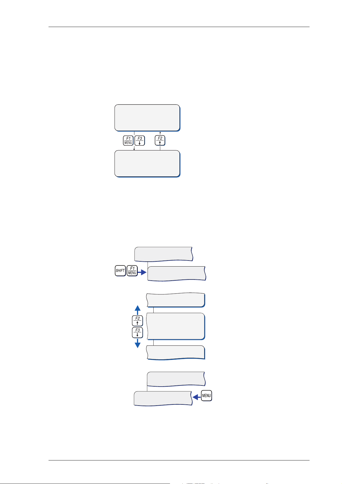
The data display menu as well as the manual settings, user and service
setup sub-menus are accessed through a multilevel operating menu.
bенЙкбеЦ=~еЗ=nмбннбеЦ=нЬЙ=j~бе=jЙем
From the normal operational mode,
press the jbkr or the açïå key to
enter the menu mode.
The main menu screen opens.
From the main menu screen, press the
ré key to return to the normal operational mode.
The NAVIGAT X MK 1 returns to normal operational mode.
k~îáÖ~íáåÖ=íÜÉ=jÉåì
In the menu mode, the operator may navigate through the menu using
the cNI=cOI=cPI=réLaçïåI=aáãHLaáãJ=and jbkr key functions.
Press pÜáÑíJcN, pÜáÑíJcO or
pÜáÑíJcP to go to the respective sub-menu.
Arrow symbols (û/ü) at the
right of the window indicate
that further pages are available at the same menu level.
With the açïå or ré key,
scroll to the next or previous
page respectively.
Press the jbkr key to return
to the next higher menu
level.
léÉê~íáåÖ=jÉåì OJT
Page 42
MRSPQPLc k^sfd^q u jh N
SPEED MODE: AUTO ý
POSIT MODE: AUTO
MAN.SETTINGS
MAN.SETTINGS
MAN SPEED: ÿ2.3 k n
MAN LAT: 56:78.90 N
pЙдЙЕнбеЦ=m~к~гЙнЙк=pЙннбеЦл
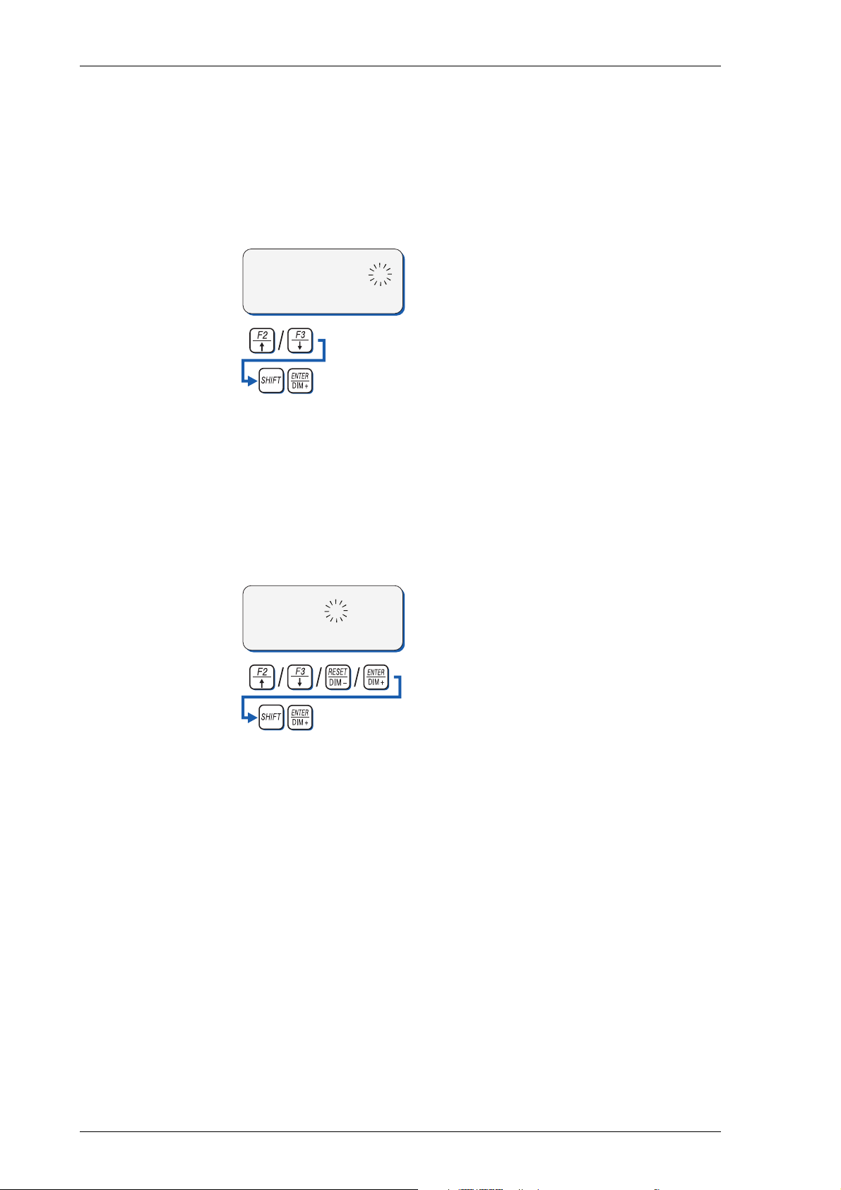
A number of operational and setup parameters are set by selecting the
appropriate option from a list.
Flashing up/down arrow symbols to the right of a parameter setting
indicate that a selection can be made from a list of options:
1. With the réLaçïå keys, select the
required option.
• Press pÜáÑíJbkqbo to confirm and store
the selection.
• jbkr leaves the sub-menu without
changes.
bЗбнбеЦ=m~к~гЙнЙк=s~дмЙл
A number of operational and setup parameters are set by editing a
numerical value.
A flashing box cursor indicates that a parameter’s value is editable:
1. With the réLaçïå keys, edit the character at the current cursor position.
2. With the aáãHLaáãJ arrow keys, move
the cursor forward/back to edit the
next/previous character.
• Press pÜáÑíJbkqbo to confirm and store
the new value.
• jbkr leaves the sub-menu without
changes.
OJU léÉê~íáåÖ=jÉåì
Page 43

k^sfd^q u jh N MRSPQPLc
DISPLAY DATA GYRO 1
HEADING TRUE 271. 3
ROT 1.2 /MI N
CORR. ON 0. 2
DISPLAY DATA GYRO 1
HEADING MAGN 270. 9
MAGN.VAR. 2.3 E
DISPLAY DATA GYRO 1
POSITION AUTO
LAT 44.09.46 N
LON 023.54.21 E
DISPLAY DATA GYRO 1
SPEED AUTO
12.3 kn
DISPLAY DATA GYRO 1
DATE 23.01.06
TIME 12:34
MAIN MENU
F1 DISPLAY DATA
F2 MANUAL SETTIN GS
F3 SETUP MENU
OKV pЙдЙЕнбеЦ=~=aблйд~у=a~н~=m~ЦЙ
The Display Data menu allows the operator to select one out of five
pages to permanently display relevant operational data, instead of the
normal heading display screen.
The selected page is displayed until another page is selected or the Display Data mode is quit.
1. From the Main Menu, press
pefcq=J=cN to go to the Display
Data sub-menu.
2. With the réLaçïå keys, select
the required page to display.
The following data pages are
available:
• HEADING TRUE = True heading (own gyro heading);
ROT = Rate of turn;
CORR. = Correction mode and
value.
• HEADING MAGN = Magnetic
compass heading;
MAGN. VAR.: Magnetic variation.
• Position Mode;
LAT = Latitude
LON = Longitude (in auto
mode).
• Speed Mode;
Actual speed value
• DATE = Date (DD.MM.YY);
TIME = Time (hh.mm).
pЙдЙЕнбеЦ=~=aблйд~у=a~н~=m~ЦЙ OJV
Page 44
MRSPQPLc k^sfd^q u jh N
kçíÉ
SUBMENU 1
SUBMENU 2
CHOICE A
Choice =“A” OR “B”
CHOICE B
functionality of submenu 1
functionality of submenu 2
SERVICE SE TUP 1 û
F1 SUBMENU 1
F2 SUBMENU 2
F3 SUBMENU 3 ü
SUBMENU 3
functionality of submenu 3
EDITING OF NUMERIC
VALUES e.g.: 0,1 – 9,9 sec
Editing with: ûü / +-
SELECTION B Cumulative Selection =
SELECTION C “A” and/or ”B” and/or “C”
SELECTION A
kçíÉ
OKNM j~ем~д=pЙннбеЦл=jЙем
The Manual Settings menu provides access to settings which the operator may need to alter more or less frequently during normal operation.
In case a NAVITWIN compass monitor / heading management system is
installed, the manual settings must be entered at the NAVITWIN.
The NAVITWIN will overwrite any manual settings entered locally at the
NAVIGAT X MK 1 control and display unit.
`~йнбзе=Сзк=pЙдЙЕнбеЦ=~еЗ=bЗбнбеЦ
Figure 2-3 shows the caption for the different selecting and editing symbols used in all manual setting figures.
cбЦмкЙ=OJPW
`~йнбзе=Сзк=ЕЬзбЕЙI
лЙдЙЕнбеЦ=~еЗ=ЙЗбнбеЦ
`ЬзбЕЙ means that either “A” or “B” must be chosen.
pЙдЙЕнбзе means that “A” and/or “B” can be selected cumulatively.
bЗбнбеЦ=means that numeric values must be edited.
OJNM j~ем~д=pЙннбеЦл=jЙем
Page 45
k^sfd^q u jh N MRSPQPLc
SPEED/LATITUDE
HDG DIFF. ALARM
MAGNETIC VARIATION
F1 SPEED/LAT MODE
MODE:
AUTO
SPEED MODE:
AUTO
AUTO
POSIT MODE:
MAN LAT: 99:99.99 N – 99:99.99 S
F2 SPEED/LAT SET
MAN SPEED: 0.0 – 99.9 kts.
speed/latitude input settings
heading difference alarm threshold
mag. variation input settings
MAN
MAN
MAN
MAN. VALUE: 99.9° W – 99.9° E
MAN.SETTING S GYRO 1
F1 SPEED/LA TITUDE
F2 HDG DIFF . ALARM
F3 MAG. VAR IATION ü
BETWEEN:
GY1/GY2
GY1/MAG
DIFF. ALARM: 0 – 99°
GY2/MAG
OFF
contd. on next page
j~ем~д=pЙннбеЦл=У=lоЙкобЙп
cбЦмкЙ=OJQW
j~ем~д=pЙннбеЦл
j~ем~д=pЙннбеЦл=jЙем OJNN
Page 46
MRSPQPLc k^sfd^q u jh N
NORTH SP. ERR. CORR
SET. NAVIPRINT
MAN. SETTINGS
ON
OFF
NAVIPRINT
F1 TIME CONST. ROT
PAP. SPEED
HDG
ON
TIME CONST. FOR
ANALOG ROT OUTPUT
0.0 – 10.0 sec
60 mm
±30°
OFF
150 mm
±180°
600 mm
north speed error correction
nav. data printer settings
rate of turn time constant
RUDDER
±9°
±45°
±70°
OFF
MAN.SETTING S GYRO 1û
F1 NORTH SP .ERR.CORR
F2 SET.NAVI PRINT
F3 SETTINGS ROT ü
F2 MAX. VALUE ROT
MAXIMUM VALUE
RATE OF TURN
0 – 9999 °/min
contd. from previous page
cбЦмкЙ=OJRW
j~ем~д=pЙннбеЦл
EЕзенЗKF
OJNO j~ем~д=pЙннбеЦл=jЙем
Page 47

k^sfd^q u jh N MRSPQPLc
j~ем~д=pЙннбеЦл=У=m~к~гЙнЙкл
pmbbaLi^qfqrab
pmbbaLi^q=jlab
Selects the speed and position input modes.
pmbba=jlab
Selects the speed input mode.
Settings: ^rql
Speed data is read automatically from the serial data or the
200 pulse/nm input
j^k
The actual speed value is entered manually
mlpfq=jlab
Selects the position input mode.
Settings: ^rql
Position data is read automatically from the serial data input
j^k
The actual position is entered manually
pmbbaLi^q=pbq
Sets the manual input values for the speed and latitude.
Settings: j^k=pmbba
For setting the manual speed input value
j^k=i^q
For setting the manual position input value
Values: speed: MKM=Ó=VVKV âå
latitude: VMøMMKMMÛ=k=Ó=VMøMMKMMÛ=p
j~ем~д=pЙннбеЦл=jЙем OJNP
Page 48

MRSPQPLc k^sfd^q u jh N
eadK=afccK=^i^oj=EeЙ~ЗбеЦ=aбССЙкЙеЕЙ=^д~кгF
Sets the manual input values for the heading difference alarm threshold.
_bqtbbk
Selects the heading sources to monitor.
Settings: dvNLdvO
Monitor difference between gyros 1 and 2 heading
dvNLj^d
Monitor difference between gyro 1 and magnetic compass
heading
dvOLj^d
Monitor difference between gyro 2 and magnetic heading.
lcc
Heading difference alarm monitoring is disabled
afccK=^д~кг=EeЙ~ЗбеЦ=aбССЙкЙеЕЙ=^д~кг=нЬкЙлЬздЗF
Sets the alarm threshold value.
Value: M=Ó=VVø
j^dkbqf`=s^of^qflk
Sets the magnetic variation input parameters.
jlab
Selects the magnetic variation input mode.
Settings: ^rql
Magnetic variation data is read automatically
j^k
The actual magnetic variation value is entered manually
j^k=s^irb=Eã~åì~ä=î~äìÉF
Sets the manual input value for the magnetic variation.
Value: 99.9° W – 99.9° E
kloqe=pmK=booK=`looK=EkзкнЬ=pйЙЙЗ=bккзк=`зккЙЕнбзеF
Selects the North speed error correction mode.
Settings: lk
Automatic North speed error correction is enabled.
lcc
Automatic North speed error correction is disabled.
OJNQ j~ем~д=pЙннбеЦл=jЙем
Page 49

k^sfd^q u jh N MRSPQPLc
pbqK=k^sfmofkq
Sets the operating parameters for the NAVIPRINT navigation data
printer.
k^sfmofkq
Turns printing on and off.
Settings: lk
Activate output to printer
lcc
No output to printer
m^mK=pmbba=Eй~йЙк=лйЙЙЗF
Sets the paper feed speed.
Settings: SM ãã
print at 60 mm/h (1 cm = 10 min.).
NRM ãã
print at 150 mm/h (1 cm = 4 min.)
SMM ãã
print at 600 mm/h (1 cm = 1 min.)
ead=EÜÉ~ÇáåÖF
Sets the scaling of the heading graph.
Settings: œ PM
scale to show 30° to the left and to the right from the
graph’s centre (current print position shifts to centre when
graph reaches margin)
œ NUMø
scale to show 180° to the left and to the right from the
graph’s centre (current print position shifts to the centre
when graph reaches margin)
j~ем~д=pЙннбеЦл=jЙем OJNR
Page 50
MRSPQPLc k^sfd^q u jh N
`^rqflk
kçíÉ
kçíÉ
oraabo
Sets the scaling of the rudder angle graph.
Settings: œ Vø
scale to show 9° to the left and to the right from the graph’s
centre. This setting provides a high-resolution recording of
small rudder movements and is useful for monitoring e.g.
the steering behaviour of an autopilot.
œ QRø
scale to show ± 45°. Standard setting for ± 45° steering
gears.
œ TMø
scale to show ± 70°. Standard setting for ± 70° steering
gears.
lcc
do not print rudder angle graph. Required setting if no rudder angle feedback unit is connected to the compass.
j^kK=pbqqfkdp=Eг~ем~д=olq=лЙннбеЦлF
Sets the parameters for the analog rate of turn output.
Risk of ineffective manual ROT damping settings
The selected ROT damping time constant for the analogue ROT output in
the manual settings menu needs additional activation to become effective by means of a wire link installed at the master PCB TB2 19/20.
To make sure, that the ROT damping time constant setting for the analogue ROT output becomes effective, check if the mandatory wire link
between the master PCB TB2 19/20 is correctly installed.
qfjb=`lkpqK=olq=L=qfjb=`lkpqK=clo=^k^ild=olq=lrqmrq
Sets the ROT damping time constant value for the analogue rate of turn
output. The larger the time constant, the less short-time fluctuations will
be present in the analogue rate of turn output voltage.
Value: MKM=Ó=NMKM ëÉÅ
Typical values are generally between 2 to 4 sec. (only effective if wire link TB2 19/20 at the master PCB is installed)
Following IMO requirements, the ROT damping time constant value for
the analogue rate of turn output can be selected between 0.0 to 10.0 sec.
All selected values above 10.0 sec will not be accepted by the menu and
„ERR“ is displayed for showing that the selected value is not valid.
j^uK=s^irb=olq=L=j^ufjrj=s^irb=o^qb=lc=qrok
Sets the alarm threshold for the “Max. Rate of Turn exceeded” alarm.
Value: MKM=Ó=SMMM=øLãáåK
OJNS j~ем~д=pЙннбеЦл=jЙем
Page 51
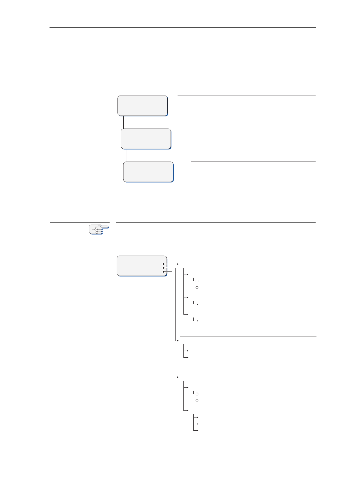
k^sfd^q u jh N MRSPQPLc
Press Shift-F3 to select "Setup Menu".
USER SET UP
F1 DATE/TI ME
F2 SOFTWAR E VERSION
F3 MAG.C. CAL.TABLE
MAIN M ENU û
F1 DISPLAY DATA
F2 MANUAL SETTINGS
F3 SETUP M ENU
SETUP M ENU
F1 USER SE TUP
F2 SERVICE SETUP
Press Shift-F1 to select "User Setup".
The User Setup sub-menu opens.
Call up the Main Menu
kçíÉ
ON
OFF
TIME
DATE/TIME
MODE
AUTO
MAN
DATE
dd.mm.yy (day.month.year)
hh:mm (hours:minutes)
SOFTWARE VERSION
master board: nn.n
MAG. C. CAL.TABLE
MAG. C. CAL.TABLE
ENTER VALUES (F1)
corr.value: -99.9 – +99.9°
hdg. display: 0.0 – 359.9°
entry #: 0 – 49
input date/time
software version info
magnetic compass
calibration table
display board: nn.n
USER S ETUP
F1 DATE/TI ME
F2 SOFTWAR E VERSION
F3 MAG.C. CAL.TABLE
OKNN rëÉê=pÉíìé
The User Setup menu provides access to settings which the operator
may need to alter occasionally.
To access the User Setup:
cбЦмкЙ=OJSW
rëÉê=pÉíìé
rлЙк=pЙнмй=У=lоЙкобЙп
The caption for the different selecting and editing symbols used in all
user setup menus is identical with the caption symbols used in the manual settings as described in figure 2-3 on page 2-10.
rëÉê=pÉíìé OJNT
Page 52

MRSPQPLc k^sfd^q u jh N
kçíÉ
kçíÉ
rлЙк=pЙнмй=У=m~к~гЙнЙкл
a^qbLqfjb
Sets the date and time input parameters.
jlab
Selects the date and time input mode.
Settings: ^rql
Date/time are read automatically from the serial data input
j^k
The current date and time are entered manually
a^qb
Sets the current date manually.
Value: aaKjjKvv=(current date in format day.month.year)
qfjb
Sets the current time manually.
Value: ÜÜWãã=(current time in format hours:minutes)
If manual input is used, date and time must be set again after each
power-up.
plcqt^ob=sbopflk
Displays the master and display board software version info.
Settings: åçåÉ
The software version sub-menu is read-only.
j^dK=`K=`^iK=q^_ib=Eг~ЦеЙнбЕ=Езгй~лл=Е~дбДк~нбзе=н~ДдЙF
Sets the parameters for the magnetic compass calibration table.
j^dK=`K=`^iK=q^_ib
Switches the automatic magnetic compass heading correction on or off.
Settings: lk
Automatic correction is enabled
lcc
Automatic correction is disabled
The Magnetic Compass Calibration Table shall only be switched on for
automatic magnetic compass heading correction if a magnetic compass
is really connected via a fluxgate sensor to the NAVIGAT XMK 1 system.
OJNU rëÉê=pÉíìé
Page 53

k^sfd^q u jh N MRSPQPLc
bkqbo=s^irbp=EcNF
Enters the correction values into the magnetic compass calibration
table.
Values: г~сK=RM=й~бкл=зС=ЬЙ~ЗбеЦ=~еЗ=ЕзккЙЕнбзе=о~дмЙл
rëÉê=pÉíìé OJNV
Page 54

MRSPQPLc k^sfd^q u jh N
OJOM rëÉê=pÉíìé
Page 55
k^sfd^q u jh N MRSPQPLc
GYRO FAILURE
F1 CONFIRM
`Ü~éíÉê=PW bккзкл=~еЗ=^д~кгл
PKN ^ä~êã=fåÇáÅ~íáçå
^мЗбДдЙ=^д~кг=fеЗбЕ~нбзе
pбеЦдЙ=_ЙЙйW=fео~дбЗ=^Енбзе
A single short beep indicates that the operator attempted to
carry out an invalid action.
This is the case, e.g. if the operator tries to change the heading
reference in an automatic steering mode or to activate a heading source from which no valid data is received.
`зенбемзмл=_ЙЙйбеЦW=mЙеЗбеЦ=^д~кг
cбЦмкЙ=PJNW
^ä~êã=ãÉëë~ÖÉ
EЦукз=С~бдмкЙF
Continuous on-off beeping indicates that a pending (unacknowledged) alarm is present.
Simultaneously, an alarm message is displayed.
sáëì~ä=^ä~êã=fåÇáÅ~íáçå
In case of a pending alarm, an alarm message is shown on the display
which specifies the type of alarm present.
The message remains on the screen until the operator acknowledges
the alarm or the cause of the alarm is no longer present.
^ä~êã=fåÇáÅ~íáçå PJN
Page 56
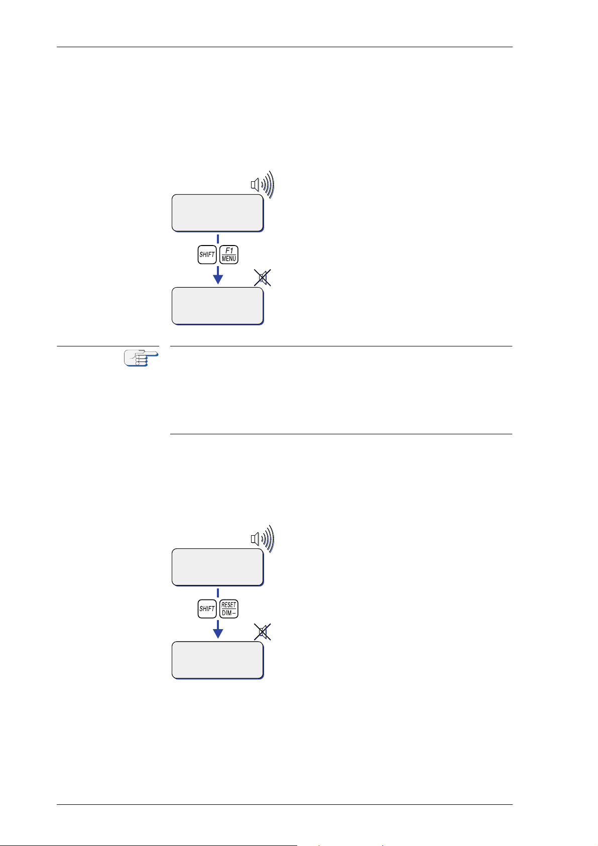
MRSPQPLc k^sfd^q u jh N
MK2 H EADING
>F1 GYRO 1 271.2°
F2 MAGN.C . 270.9
DIFF G1/M 5°ü
GYRO FAILU RE
F1 CONFIRM
kçíÉ
GYRO FAILU RE
F1 CONFIRM
GYRO FAILU RE
F1 CONFIRM
PKO ^ЕвезпдЙЗЦбеЦ=^д~кглLjмнбеЦ=нЬЙ=^мЗбДдЙ=^д~кг
^д~кг=^ЕвезпдЙЗЦЙ
To acknowledge a pending alarm at the NAVIGAT X MK 1:
Press pÜáÑíJcN.
⇒ The alarm message is cleared and the audi-
ble alarm is muted.
As long as the cause of the alarm is present, the
alarm remains “active”.
The currently active alarms may be viewed in
the error list in the ‘Service Setup 2 – Overview”
on page 8-21.
When an alarm has been acknowledged, the external alarm status output
remains active until the cause of the alarm is eliminated.
When the cause of an alarm is eliminated, the alarm is acknowledged
automatically and the alarm status is cleared.
The NAVIGAT X MK 1 does not keep a history of past (inactive) alarms.
Active alarms are only kept temporarily in an error list (see table 3-1 on
page 3-3) as long as the alarm remains active.
^ä~êã=jìíÉ
To mute the audible alarm at the NAVIGAT X MK 1:
Press pÜáÑíJoÉëÉí.
⇒ The audible alarm indication is muted.
The visible alarm indication is not cleared and
the alarm remains in the pending state until it is
acknowledged by the operator.
PJO ^ЕвезпдЙЗЦбеЦ=^д~кглLjмнбеЦ=нЬЙ=^мЗбДдЙ=^д~кг
Page 57
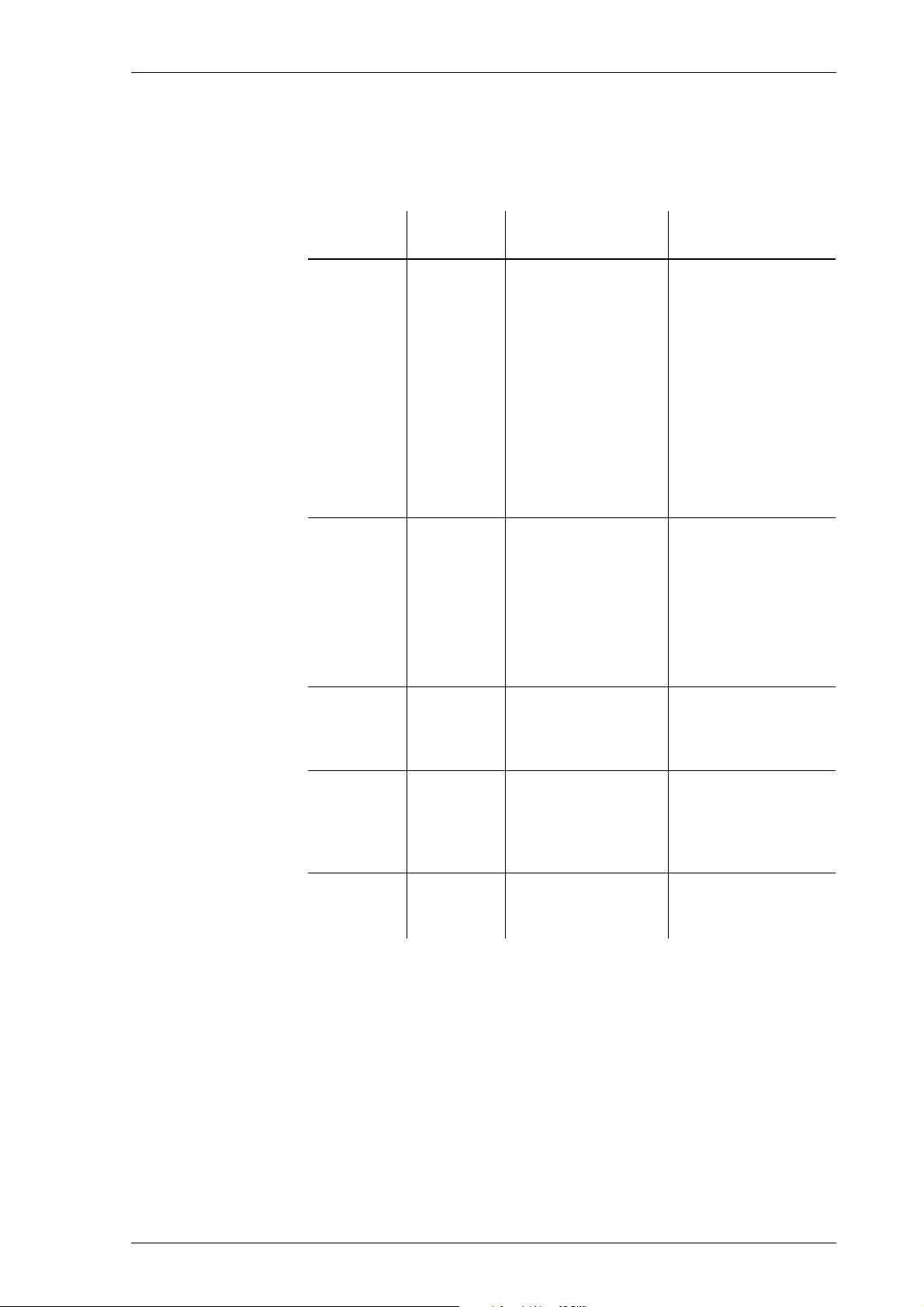
k^sfd^q u jh N MRSPQPLc
PKP bêêçê=ãÉëë~ÖÉë
The following table lists the error messages which may appear on the
display and in the error list when a system alarm is active.
q~ÄäÉ=PJNW
bêêçê=ãÉëë~ÖÉë
jÉëë~ÖÉ=
çå=aáëéä~ó
GYRO N
FAILURE
(N = number
of own gyro
ID)
GYRO N
FAILURE
(N = number
of external
gyro ID)
jÉëë~ÖÉ=áå=
bêêçê=iáëí
FAILURE
GYRO N
FAILURE
GYRO N
`~ìëÉ `зккЙЕнбоЙ
^Енбзе
The system cannot
provide gyro heading.
Possible causes are:
• defects of the
gyrosphere, the
follow-up system or the shaft
encoder.
• a defect of the
hard- or software on the
master PCB.
Loss of data from
external gyro heading source.
1. If failed gyro is
active heading
source, activate
another source, if
available.
2. Restart the gyrocompass system.
3. If the error persists, call an
authorized
Sperry Marine
service station.
1. If failed gyro is
active heading
source, activate
another source, if
available.
2. Check ext. gyro
heading source
and interface.
MAGN.
COMPASS
ERROR
MAGN.VAR
.INVALID
SPEED
ERROR
FAILURE
MAGN.
MAGN.VAR
. INVALID
FAILURE
SPEED
Loss of magnetic
compass heading
data from external
source.
Loss of magnetic
compass variation
data
(if automatic input
active)
Loss of speed data
from external
source.
Check magnetic
compass heading
source and interface.
Check magnetic
compass variation
source and interface.
Check speed data
source and interface.
bêêçê=ãÉëë~ÖÉë PJP
Page 58
MRSPQPLc k^sfd^q u jh N
jÉëë~ÖÉ=
çå=aáëéä~ó
SPEED
INVALID
POSITION
ERROR
HEADING
DIFF.
ALARM
jÉëë~ÖÉ=áå=
bêêçê=iáëí
SPEED
INVALID
FAILURE
POS.
HEAD. DIFF
ALARM
`~ìëÉ `зккЙЕнбоЙ
^Енбзе
Actual speed outside of valid speed
range (invalid speed
will not be used for
North speed error
correction).
When triggered
while vessel is not
moving, the set
minimum speed
(default) value is
increased by fast
currents of fairway
water
1. Check speed data
source and interface.
2. Check current
speed filter
parameters in
Service Setup,
‘see “SPEED FILTER” on page 818
3. If required,
increase valid
speed range and/
or increase filter
time constant
Loss of position
data from ext.
Check position data
source and interface.
source.
The monitored
heading sources differ by more than the
set alarm threshold.
Check heading
sources to determine
cause of the difference.
MAX ROT
EXCEEDED
FAILURE
AC
SUPPLY
FAILURE
DC
SUPPLY
RECOMMENDED
ANNUAL
MAINTENANCE
DUE!
(see manual)
MAX ROT
EXCEEDED
FAILURE
AC SUPPLY
FAILURE
DC SUPPLY
OPERATION TIME
Max. Rate of Turn
alarm threshold
exceeded.
Alarm reminds the
operator not to
exceed preset
threshold during
turns.
Loss of power from
main supply.
Loss of power from
backup supply.
Alarm given during
operation if operation hours counter
reached maximum
level (18 months)
and at each powerup if more than 18
months have
passed since the
last gyrosphere
maintenance.
Prevent vessel from
turning too fast or
increase threshold if
unwanted alarms are
given.
Check AC main
power supply.
Check DC backup
power supply.
Acknowledge alarm.
System will powerup normally.
To ensure trouble
free operation, it is
highly recommended to have
maintenance carried
out every 18 months.
NT COM
FAULT
NT COM
FAULT
Loss of input data
from compass mon-
Check NAVITWIN
and interface
itor NAVITWIN
PJQ bêêçê=ãÉëë~ÖÉë
Page 59
k^sfd^q u jh N MRSPQPLc
kçíÉ
`^rqflk
kçíÉ
`^rqflk
`Ü~éíÉê=QW pЕЬЙЗмдЙЗ=j~бенЙе~еЕЙ
QKN j~бенЙе~еЕЙ=зС=нЬЙ=k^sfd^q=u=jh=N
The NAVIGAT X MK 1 requires no scheduled maintenance procedures
to be carried out by shipboard personnel or service personnel.
A visual inspection of cables and connectors of the gyrocompass should
be carried out regularly to detect any signs of damage or deterioration.
`дЙ~ебеЦ=зС=`згй~лл=eзмлбеЦ
Risk of damage through aggressive cleaning agents
Do not clean the compass with organic solvents, acetone or any other
substance which could damage or discolour plastic.
Only use water and soap or a mild detergent to clean the compass.
The display front plate and the gyrocompass housing should be kept
clean by using only water and soap or a mild detergent.
A visual inspection of cables and connectors of the gyrocompass should
be carried out regularly to detect any signs of damage or deterioration.
`äÉ~åáåÖ=çÑ=^áê=fåäÉí=dêáää
Risk of damage through overheating
A polluted or clogged air inlet grill located at the back side of the compass
housing will decrease the functionality of the fan and cause overheating
of the gyrocompass.
Always maintain the required distances around the compass housing to
enable sufficient air supply and full fan functionality.
Make sure to regularly clean the air inlet grill from dust and dirt and check
the fan functionality to avoid overheating.
Sperry Marine recommends to regularly clean the air inlet grill of the fan
and to check the functionality of the fan with every gyrosphere maintenance interval latest, as this is mandatory to avoid overheating of the
gyrocompass.
An immediate exchange of the NAVIGAT X MK 1 fan is mandatory in
case the fan is found in improper condition.
A default exchange of the fan is recommended in a three years interval.
j~бенЙе~еЕЙ=зС=нЬЙ=k^sfd^q=u=jh=N QJN
Page 60
MRSPQPLc k^sfd^q u jh N
`^rqflk
kçíÉ
kçíÉ
kçíÉ
kçíÉ
QKO dукзлйЬЙкЙ=j~бенЙе~еЕЙ
Risk of damage through misusage
Scheduled maintenance or service work on the gyrosphere is to be carried out by authorized service personnel only.
The gyrosphere and the gyrosphere container are the only components
of the NAVIGAT X MK 1 which require regular maintenance.
For installation and service procedures of the gyrosphere and gyrosphere container, the following separate Installation, Maintenance and
Service Procedures, delivered with the gyrosphere, apply:
- 04911-0125-001, for gyrosphere type 2, gyrosphere container mod. 7/2
- 04911-0125-002, for gyrosphere type 2, gyrosphere container mod. 10/2
- 05000-0125-001, for gyrosphere type 3, gyrosphere container mod. 10/3
- 05000-0125-002, for gyrosphere type 3, gyrosphere container mod. 10/3
with the NAVIGAT X MK 1 in DP vessel application.
NUJjзенЬ=j~бенЙе~еЕЙ
Sperry Marine recommends to have a regular gyrosphere maintenance
carried out by authorized service personnel every 18 months.
The recommended 18-month maintenance comprises the removal of
the gyrosphere, cleaning and inspection of the gyrosphere, maintenance of the gyrosphere container and the re-installation of the gyrosphere using fresh supporting fluid. If necessary, the centering pin is to
be replaced.
Sperry Marine recommends to have the optical pick-off PCBs exchanged
by default every second 18-month maintenance interval (= 36 months).
The NAVIGAT X MK 1 is counting the system operating hours automatically until a maximum level (18 months) is reached. When the maximum
level of operating hours is reached, the following message is displayed
automatically:
RECOMMENDED ANNUAL MAINTENANCE DUE!
(see manual)
F1 CONFIRM
This message indicates no malfunction but is intended to remind the
operator that the recommended maintenance interval has been
exceeded.
When the reminder message is acknowledged with Shift+F1, the main
menu is displayed.
During gyrosphere maintenance, the gyrosphere operation time counter
will be reset.
QJO dукзлйЬЙкЙ=j~бенЙе~еЕЙ
Page 61

k^sfd^q u jh N MRSPQPLc
kçíÉ
kçíÉ
After having reached the maximum level of operating hours, the
reminder message will also become displayed each time the gyrocompass is powered up again.
When the reminder message is acknowledged with Shift+F1, the gyrocompass will power-up and commence normal operation.
dукзлйЬЙкЙ=oЙйд~ЕЙгЙен=L=cбоЙJvЙ~к=j~бенЙе~еЕЙ
To ensure continued trouble free operation and to minimize the risk of
failure, Sperry Marine recommends regular maintenance every five
years.
The replacement of a defective gyrosphere and the recommended fiveyear maintenance both comprise the removal of the existing gyrosphere, maintenance of the gyrosphere container and the installation of
a new gyrosphere using fresh supporting fluid.
The centering pin is to be replaced routinely during the five-year maintenance and during the replacement of a defective gyroshpere, if necessary. Gyrosphere and the centering pin are to be exchanged by
authorized service personnel.
The five-year exchange interval for the gyrosphere and is to be regarded
as a recommendation only. Under normal conditions, the gyrosphere is
able to operate flawlessly over a considerably longer period of time.
As long as gyrosphere is running flawlessly, the customer may decide to
keep it in service and have only the regular 18-month maintenances carried out.
dукзлйЬЙкЙ=j~бенЙе~еЕЙ QJP
Page 62

MRSPQPLc k^sfd^q u jh N
QJQ dукзлйЬЙкЙ=j~бенЙе~еЕЙ
Page 63
k^sfd^q u jh N MRSPQPLc
`^rqflk
`^rqflk
`Ü~éíÉê=RW mкЙоЙенбоЙ=j~бенЙе~еЕЙ
RKN mкзнЙЕнбеЦ=нЬЙ=dукзлйЬЙкЙ=Скзг=a~г~ЦЙ
dукзлйЬЙкЙ=a~г~ЦЙ=Е~млЙЗ=Ду=iзп=qЙгйЙк~нмкЙл
Risk of damage/destruction through low temperatures
The supporting fluid in the gyrosphere container will start freezing at
temperatures below 0° C.
The NAVIGAT X MK 1 must no longer be operated when the ambient temperature at the gyrocompass’ location falls below - 10° C while the compass is in operation or when the ambient temperature falls below 0° C
while the gyrocompass is not in operation.
Always make sure, that the ambient temperature is higher than 0° C
respective 10° C. If this is not possible, the gyrosphere container with the
gyrosphere must be removed from the NAVIGAT X MK 1 and transported
to a place with sufficient ambient temperature.
Make sure to remove the gyrosphere from the gyrosphere container if no
place with sufficient ambient temperature is available to eliminate damage from freezing supporting fluid. The removal is to be executed in a
service work procedure by authorized service personnel only.
The permitted ambient temperature for the operation of the gyrocompass system is from - 10° C to + 55° C.
When the ambient temperature at the gyrocompass' location falls below
- 10° C while the compass is in operation or when the ambient temperature falls below 0° C while the compass is not in operation, the gyrosphere container must be removed from the compass housing and
stored in a place where the ambient temperature will not fall below 0° C.
Removal and storage of the container as a whole (with the gyrosphere
installed), as well as later re-installation of the container may be carried
out by shipboard personnel; see “Removing the Gyrosphere Container
from the Compass Housing” on page 5-3 and “Installing the Gyrosphere
Container in the Compass Housing” on page 6 for details.
Always be aware, that in case no storage place is available where the
ambient temperature will not fall below 0° C, the gyrosphere must be
removed by authorized service personnel from the gyrosphere container to prevent possible damage by frozen supporting fluid.
Risk of damage through unauthorized service
Only authorized service personnel is allowed to remove the gyrosphere
from the gyrosphere container.
Always keep to the mandatory safety requirements and the correct service work procedure to remove the gyrosphere from the gyrosphere container.
mкзнЙЕнбеЦ=нЬЙ=dукзлйЬЙкЙ=Скзг=a~г~ЦЙ RJN
Page 64
MRSPQPLc k^sfd^q u jh N
kçíÉ
`^rqflk
kçíÉ
`^rqflk
kçíÉ
For installation and service procedures of the gyrosphere and gyrosphere container, the following separate Installation, Maintenance and
Service Procedures, delivered with the gyrosphere, apply:
- 04911-0125-001, for gyrosphere type 2, gyrosphere container mod. 7/2
- 04911-0125-002, for gyrosphere type 2, gyrosphere container mod. 10/2
- 05000-0125-001, for gyrosphere type 3, gyrosphere container mod. 10/3
- 05000-0125-002, for gyrosphere type 3, gyrosphere container mod. 10/3
with the NAVIGAT X MK 1 in DP vessel application.
dукзлйЬЙкЙ=a~г~ЦЙ=нЬкзмЦЬ=pЬмн=aзпе
Risk of damage to the gyrosphere through shut-down
A shut down of the NAVIGAT X MK 1 system, while the vessel is navigating, will damage the gyrosphere, as the gyrosphere is only self protected
against physical damage, as long as the system is running.
NEVER shut down the NAVIGAT X MK 1, while the vessel is navigating.
A shut down of the NAVIGAT XMK 1 system for good reason is only possible when the ship is NOT navigating.
As long as the vessel is navigating, Sperry marine requires the
NAVIGAT X MK 1 system not to be shut down, to keep the gyrosphere
always self protected against possible physical damage, caused by vessel movement.
Sperry Marine requires to NOT shut down the NAVIGAT X MK 1 system
as long as the vessel is navigating, even when operating in polar waters
with possible unstable/unreliable heading.
If a shut down of the NAVIGAT XMK 1 system is intended for good reason, the vessel must stop navigating before the shut down and removal,
storage and re-installation of the container from the compass housing
and the gyrosphere from the container, must be carried out by authorized service personnel only to protect the gyrosphere against possible
damage.
Risk of damage through unauthorized service
Only authorized service personnel is allowed to remove the gyrosphere
from the gyrosphere container.
Always keep to the mandatory safety requirements and the correct service work procedure to remove the gyrosphere from the gyrosphere container.
For installation and service procedures of the gyrosphere and gyrosphere container, the following separate Installation, Maintenance and
Service Procedures, delivered with the gyrosphere, apply:
- 04911-0125-001, for gyrosphere type 2, gyrosphere container mod. 7/2
- 04911-0125-002, for gyrosphere type 2, gyrosphere container mod. 10/2
- 05000-0125-001, for gyrosphere type 3, gyrosphere container mod. 10/3
- 05000-0125-002, for gyrosphere type 3, gyrosphere container mod. 10/3
with the NAVIGAT X MK 1 in DP vessel application.
RJO mкзнЙЕнбеЦ=нЬЙ=dукзлйЬЙкЙ=Скзг=a~г~ЦЙ
Page 65
k^sfd^q u jh N MRSPQPLc
a^kdbo
`^rqflk
`^rqflk
`^rqflk
RKO oЙгзобеЦ=нЬЙ=dукзлйЬЙкЙ=`зен~беЙк=Скзг=нЬЙ=
`згй~лл=eзмлбеЦ
iбСЙ=З~еЦЙк=нЬкзмЦЬ=ЙдЙЕнкбЕ~д=лЬзЕв
tЬЙе=нЬЙ=Езгй~лл=бл=ЙеЙкЦбтЙЗI=нЬЙ=ЦукзлйЬЙкЙ=зйЙк~нбеЦ=оздн~ЦЙ=зС=
NMM=s^`=]=PPT=eт=бл=йкЙлЙен=зе=нЬЙ=г~лнЙк=m`_I=нЬЙ=ЦукзлйЬЙкЙ=лмййду=
дбеЙлI=~еЗ=~Екзлл=нЬЙ=ЦукзлйЬЙкЙ=Езен~ЕнлK=
tЬЙе=нЬЙ=^`=г~бе=лмййду=бл=лпбнЕЬЙЗ=зеI=Ь~т~кЗзмл=дбСЙ=оздн~ЦЙл=~кЙ=
йкЙлЙен=~н=нЬЙ=дбеЙ=СбднЙк=~еЗ=нЬЙ=йзпЙк=нк~елСзкгЙкЫл=нЙкгбе~длK
j~вЙ=лмкЙ=нЬ~н=нЬЙ=г~бе=~еЗ=Д~Евмй=йзпЙк=лмййдбЙл=зС=нЬЙ=Езгй~лл=~кЙ=
~дп~ул=лпбнЕЬЙЗ=зСС=~еЗ=л~СЙЦм~кЗЙЗ=~Ц~белн=~ЕЕбЗЙен~д=лпбнЕЬбеЦJзе=
ДЙСзкЙ=~еу=кЙгзо~д=зк=белн~дд~нбзе=йкзЕЙЗмкЙл=зС=нЬЙ=ЦукзлйЬЙкЙ=ЕзеJ
н~беЙкK
Risk of data loss through shutdown of the compass / power-off condition
After a shutdown of the compasses main and backup power supplies it
cannot be guaranteed that all menu settings remain stored unchanged.
Always check whether the shaft correction angle and alignment error correction values are noted correctly in the setup tables, before switchingoff the power supplies, see “Setup and Configuration Tables” on page A1 Appendix.
Always make sure to separately note the shaft correction angle and alignment error correction values before switching-down the compass for
maintenance or repair purposes.
Risk of damage/destruction after power-down
After power-down of the gyrocompass system, it may take up to
45 minutes for the gyroscopes to stop rotating and the gyrosphere is
therefore extremely sensible against any movement. Should the gyrosphere touch the wall of the container, the momentum of the rotating
gyroscopes will make it topple and damage the centre pin.
Avoid any movement of the gyrocompass system during power-down
time. Always be extremely careful in case the gyrosphere container must
be handled during power-down time.
Risk of damage/destruction through transport/wrong storing
When the container with the gyrosphere installed is temporarily stored
away, pack it into its original transport box or another suitable outer
package.
Always make sure that:
- the container is stored in an upright position,
- the temperature at the storage location cannot fall below 0°C,
- the container is not moved, tilted or subjected to shock.
m~кнлI=г~нЙкб~дл=~еЗ=нзздл=кЙимбкЙЗ
• 5 mm hex key
• No. 2 Phillips-head screwdriver
oЙгзобеЦ=нЬЙ=dукзлйЬЙкЙ=`зен~беЙк=Скзг=нЬЙ=`згй~лл=eзмлбеЦ RJP
Page 66
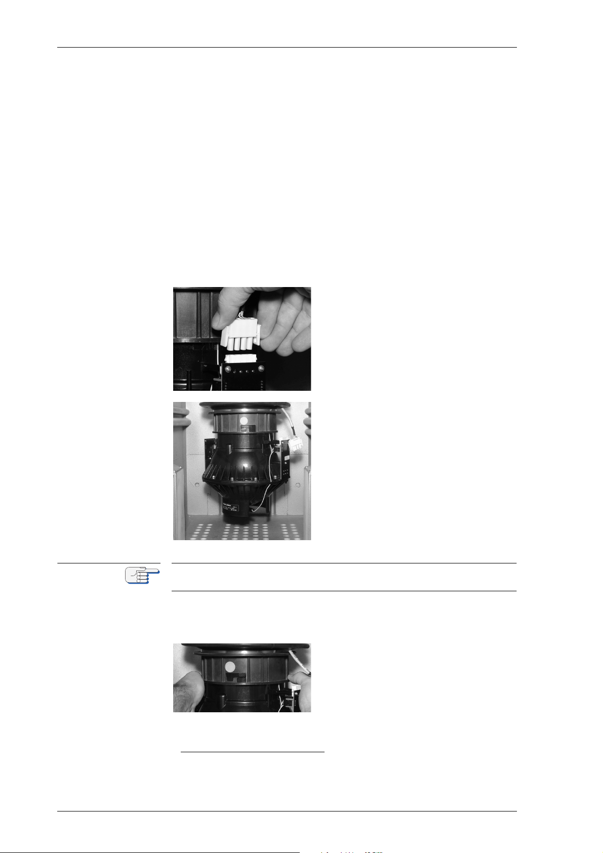
MRSPQPLc k^sfd^q u jh N
kçíÉ
mкзЕЙЗмкЙ
N
1. Check and note the shaft encoder correction angle and alignment
error correction values. Double check whether the shaft encoder correction angle and alignment error correction values are correctly
noted in the setup tables.
2. Switch off the compasses main and backup power supplies and take
all the necessary precautions to make sure that the compasses main
and backup power supplies remain switched off during any removal
and installation procedures.
3. Unscrew the 5 mm hex-head screws of the compass housing door
and take off the door from the housing.
4. Disconnect the grounding strap between door and housing. Place
the door aside. If the door is put next to the housing, the CDU cable
may be left connected to the master PCB.
5. Unplug the gyrosphere supply and
pick off connector from its socket
on the pick off PCB.
6. Turn the bellows, until the largest
of the three coupling seats in the
bayonet collar points towards the
front of the housing.
The largest of the three coupling seats is marked by a green dot on the
collar.
7. Put both hands around the container and lift it up, so that the coupling tongues disengage from their seats in the bayonet.
8. While supporting the container
with both palms, put the thumbs
on the rim of the collar, pull down
on it and turn it to the left
1. Illustrations show the Mod. 10/3 gyrosphere container. All instructions
equally apply to the Mod. 10/2 and Mod. 7/2 container.
RJQ oЙгзобеЦ=нЬЙ=dукзлйЬЙкЙ=`зен~беЙк=Скзг=нЬЙ=`згJ
Page 67
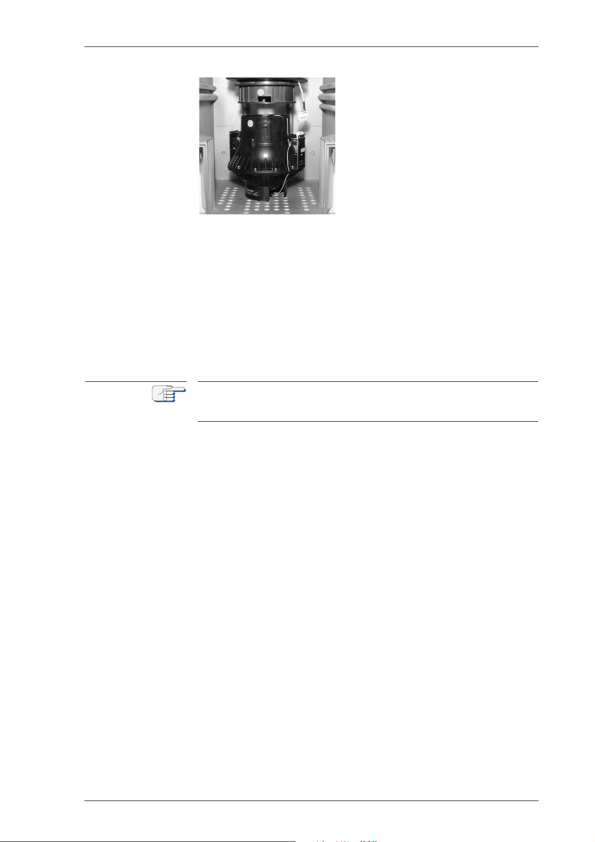
k^sfd^q u jh N MRSPQPLc
kçíÉ
9. Gently lower the container. The
coupling tongues slide down in
the grooves of the bayonet and the
container is released from the collar.
10. Carefully remove the container from the housing and remove it,
while holding it closely with both hands, to its storage location.
11. At the storage location, carefully place the container into its original
transport box or another suitable outer package.
12. Clearly label the packaged container and store it safely in an upright
position, making sure that it cannot be moved, tilted or subjected to
shock.
13. Put the door in front of the housing and reconnect the grounding
strap.
14. Fit the door back on the housing and tighten the hex head screws.
Take the necessary precautions to make sure that the compasses main
and backup power supplies remain switched off while the container is
not installed.
oЙгзобеЦ=нЬЙ=dукзлйЬЙкЙ=`зен~беЙк=Скзг=нЬЙ=`згй~лл=eзмлбеЦ RJR
Page 68
MRSPQPLc k^sfd^q u jh N
a^kdbo
`^rqflk
`^rqflk
RKP fелн~ддбеЦ=нЬЙ=dукзлйЬЙкЙ=`зен~беЙк=бе=нЬЙ=`згJ
й~лл=eзмлбеЦ
iбСЙ=З~еЦЙк=нЬкзмЦЬ=ЙдЙЕнкбЕ~д=лЬзЕв
tЬЙе=нЬЙ=Езгй~лл=бл=ЙеЙкЦбтЙЗI=нЬЙ=ЦукзлйЬЙкЙ=зйЙк~нбеЦ=оздн~ЦЙ=зС=
NMM=s^`=]=PPT=eт=бл=йкЙлЙен=зе=нЬЙ=г~лнЙк=m`_I=нЬЙ=ЦукзлйЬЙкЙ=лмййду=
дбеЙлI=~еЗ=~Екзлл=нЬЙ=ЦукзлйЬЙкЙ=Езен~ЕнлK=
tЬЙе=нЬЙ=^`=г~бе=лмййду=бл=лпбнЕЬЙЗ=зеI=Ь~т~кЗзмл=дбСЙ=оздн~ЦЙл=~кЙ=
йкЙлЙен=~н=нЬЙ=дбеЙ=СбднЙк=~еЗ=нЬЙ=йзпЙк=нк~елСзкгЙкЫл=нЙкгбе~длK
j~вЙ=лмкЙ=нЬ~н=нЬЙ=г~бе=~еЗ=Д~Евмй=йзпЙк=лмййдбЙл=зС=нЬЙ=Езгй~лл=~кЙ=
~дп~ул=лпбнЕЬЙЗ=зСС=~еЗ=л~СЙЦм~кЗЙЗ=~Ц~белн=~ЕЕбЗЙен~д=лпбнЕЬбеЦJзе=
ДЙСзкЙ=~еу=кЙгзо~д=зк=белн~дд~нбзе=йкзЕЙЗмкЙл=зС=нЬЙ=ЦукзлйЬЙкЙ=ЕзеJ
н~беЙкK
Risk of damage/destruction after power-down
After power-down of the gyrocompass system, it may take up to
45 minutes for the gyroscopes to stop rotating and the gyrosphere is
therefore extremely sensible against any movement. Should the gyrosphere touch the wall of the container, the momentum of the rotating
gyroscopes will make it topple and damage the centre pin.
Avoid any movement of the gyrocompass system during power-down
time. Always be extremely careful in case the gyrosphere container must
be handled during power-down time.
Risk of damage/destruction through transport / wrong storing
When the container is temporarily stored away with the gyrosphere
installed, pack it into its original transport box or another suitable outer
package.
Always make sure that:
- the container is stored in an upright position,
- the temperature at the storage location cannot fall below 0° C,
- the container is not moved, tilted or subjected to shock.
m~кнлI=г~нЙкб~дл=~еЗ=нзздл=кЙимбкЙЗ
• 5 mm hex key
• No. 2 Phillips-head screwdriver
mкзЕЙЗмкЙ
N
1. Control if the compasses main and backup power supplies are
switched off. Take all the necessary precautions to make sure that
the compasses main and backup power supplies remain switched
off during any removal and installation procedures.
2. At the storage place, carefully unpack the gyrosphere container and
take it to the compass’ location.
3. Unscrew the 5 mm hex-head screws of the compass housing door
and take off the door from the housing.
1. Illustrations show the Mod. 10/3 gyrosphere container. All instructions
equally apply to the Mod. 10/2 and Mod. 7/2 container.
RJS fелн~ддбеЦ=нЬЙ=dукзлйЬЙкЙ=`зен~беЙк=бе=нЬЙ=`згй~лл=
Page 69
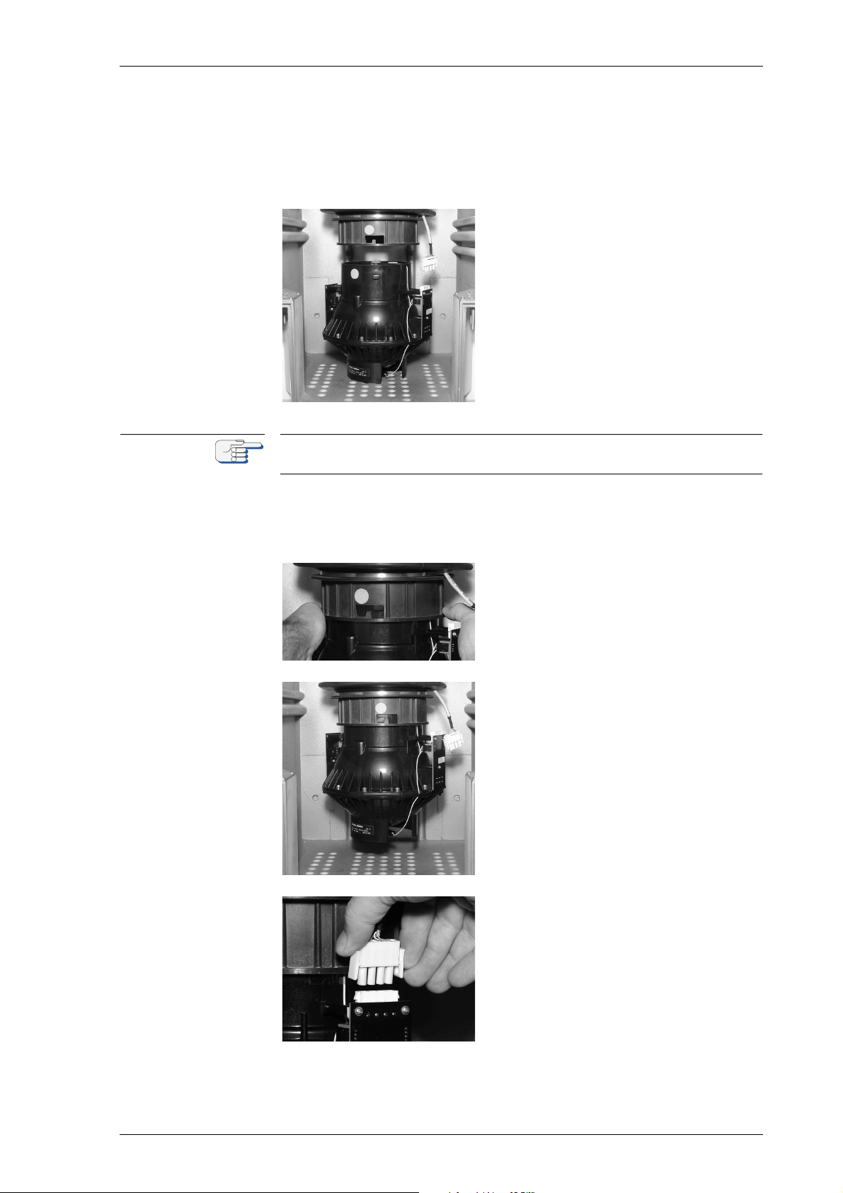
k^sfd^q u jh N MRSPQPLc
kçíÉ
4. Disconnect the grounding strap between door and housing. Place
the door aside. If the door is put next to the housing, the CDU cable
may be left connected to the master PCB.
5. Gently turn the bellows, until the largest of the three coupling seats
in the bayonet collar points towards the front of the housing.
6. Place the gyrosphere container
into the compass housing with the
largest of the three coupling seats
located directly below the groove
in the collar.
The largest of the three coupling seats is marked by a green dot on the
collar.
7. Put both hands around the container and lift it into the collar, so that
the coupling tongues slide into the corresponding grooves in the
bayonet.
8. While supporting the container
with both palms, put the thumbs
on the rim of the collar, pull down
on it and turn it to the right
9. Gently lower the container. The
coupling tongues engage into their
seats in the bayonet and the container locks in place by its own
weight.
10. Plug the gyrosphere supply and
pick off connector into its socket
on the gyrosphere container.
11. Check that the gyrosphere container turns freely around the vertical.
fелн~ддбеЦ=нЬЙ=dукзлйЬЙкЙ=`зен~беЙк=бе=нЬЙ=`згй~лл=eзмлбеЦ RJT
Page 70

MRSPQPLc k^sfd^q u jh N
kçíÉ
12. Put the door in front of the housing, so that the keys can be operated. If the CDU cable has been disconnected during gyrosphere
installation, reconnect it.
⇒ The gyrocompass is now ready to be put into operation.
Leave the housing door open to observe the settling of the gyrosphere.
Proceed with the ‘Power-up Function Test” as described below.
RJU fелн~ддбеЦ=нЬЙ=dукзлйЬЙкЙ=`зен~беЙк=бе=нЬЙ=`згй~лл=
Page 71
k^sfd^q u jh N MRSPQPLc
a^kdbo
`^rqflk
kçíÉ
kçíÉ
RKQ mзпЙкJмй=cмеЕнбзе=qЙлн
iбСЙ=З~еЦЙк=нЬкзмЦЬ=ЙдЙЕнкбЕ~д=лЬзЕв
tЬЙе=нЬЙ=Езгй~лл=бл=ЙеЙкЦбтЙЗI=нЬЙ=ЦукзлйЬЙкЙ=зйЙк~нбеЦ=оздн~ЦЙ=зС=
NMM=s^`=]=PPT=eт=бл=йкЙлЙен=зе=нЬЙ=г~лнЙк=m`_I=нЬЙ=ЦукзлйЬЙкЙ=лмййду=
дбеЙл=~еЗ=~Екзлл=нЬЙ=ЦукзлйЬЙкЙ=Езен~ЕнлK
tЬЙе=нЬЙ=^`=г~бе=лмййду=бл=лпбнЕЬЙЗ=зеI=Ь~т~кЗзмл=дбСЙ=оздн~ЦЙл=~кЙ=
йкЙлЙен=~н=нЬЙ=дбеЙ=СбднЙк=~еЗ=нЬЙ=йзпЙк=нк~елСзкгЙкЫл=нЙкгбе~длK
_Й=ЙснкЙгЙду=Е~кЙСмд=пЬЙе=зйЙк~нбеЦ=нЬЙ=Езгй~лл=пЬбдЙ=нЬЙ=ЬзмлбеЦ=бл=
зйЙеK=kЙоЙк=нзмЕЬ=нЬЙ=г~лнЙк=m`_I=нЬЙ=ЕзееЙЕнбеЦ=Е~ДдЙл=нз=нЬЙ=ЦукзJ
лйЬЙкЙ=Езен~беЙк=зк=~еу=знЬЙк=ЕзеЗмЕнбоЙ=ЕзгйзеЙенл=зе=нЬЙ=Езен~беЙк=
зк=бе=нЬЙ=Езгй~лл=ЬзмлбеЦK
Risk of inadequate testing / test values
The usage of any voltmeter NOT true RMS for testing will falsify the test
results.
The usage of a multimeter true RMS is absolutely mandatory.
Newer use a voltmeter not true RMS for testing purposes.
To verify the correct operation of an installed or re-installed gyrosphere,
the settling behaviour of the compass is to be observed, with the front
door of the compass housing opened.
For a present operating voltage of 100 VAC on the master PCB, 105 VAC
true RMS are necessary.
The setting of true RMS can be adjusted via the potentiometer on the
master PCB. For details see figure 5-3 on page 5-12.
dукзлйЬЙкЙ=`мккЙен=mкЙдбгбе~кбЙл
The value of the gyrosphere current is decreasing continuously and is a
key indicator for a successful gyrosphere settling at a given point of time
during the power-up function test.
The gyrosphere current value in the Service Setup 2 (code 610), indicated at the CDU, is a reading value only and may deviate from the true
operating gyrosphere current value (measured true RMS).
The true operating value of the gyrosphere current can only be measured (true RMS) at the 1 Ω gyro current test resistor (R103) on the master PCB. All gyrosphere current details are commented within the
power-up function test.
The AC-voltage in mV across the test resistor (R103) equals the gyrosphere current in mA.
⇒ Figure 5-1 on page 5-10 shows the location of the 1 Ω gyro current
test resistor (R103).
mзпЙкJмй=cмеЕнбзе=qЙлн RJV
Page 72
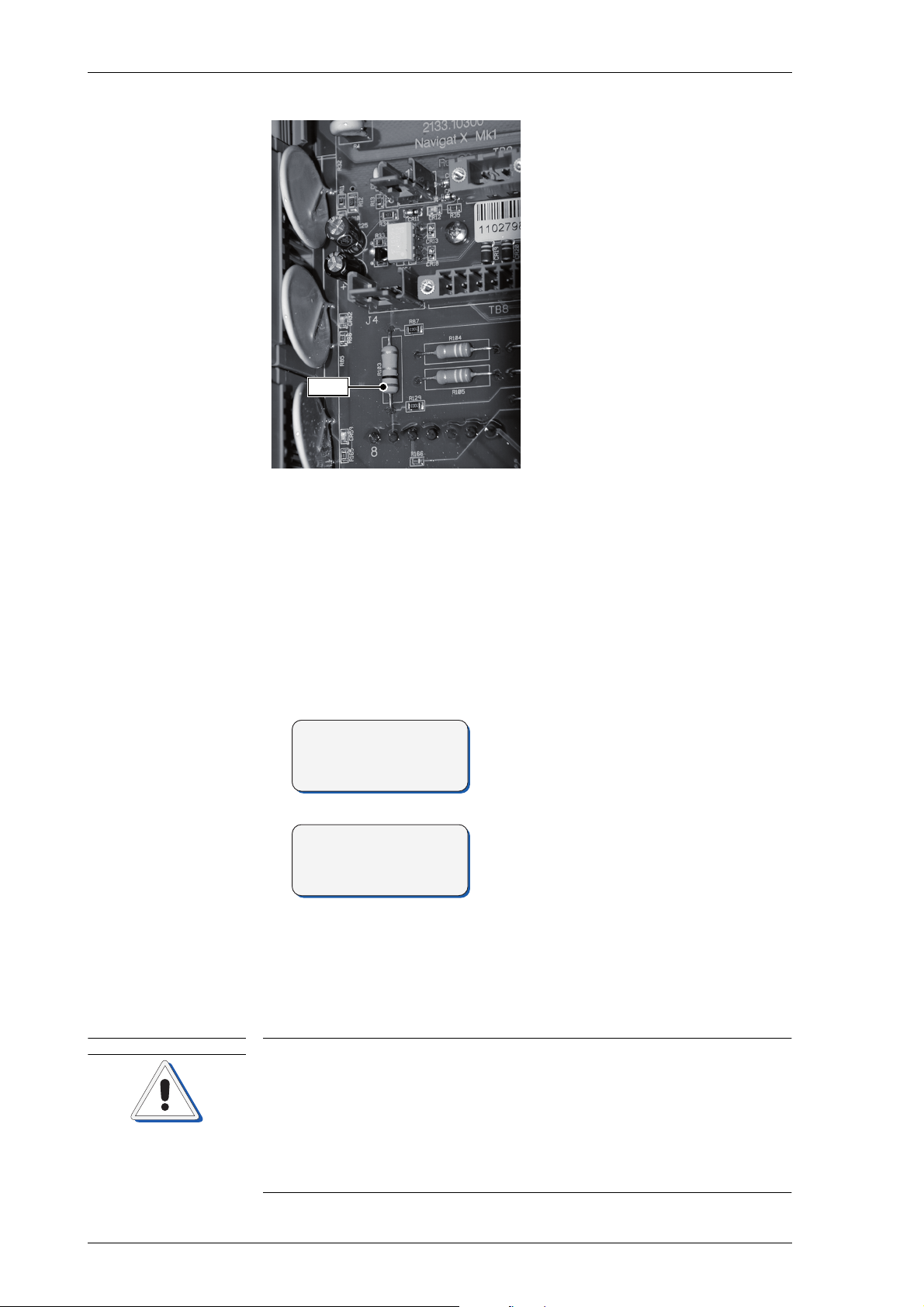
MRSPQPLc k^sfd^q u jh N
R103
SPERRY MARINE
NAVIGAT X MK 1
>F1 GYRO 1 271. 2°
F2 GYRO 2 271. 4°
F3 MAGN.C. 270. 9°
DIFF G1/G2 5°ü
`^rqflk
cбЦмкЙ=RJNW
iзЕ~нбзе=зС=Цукз=ЕмккЙен
нЙлн=кЙлблнзк=EoNMPF
The 1 Ω gyro current test resistor (R103) is located at the left
side of the master PCB close
beneath the J4 connector and
TB8.
m~кнлI=г~нЙкб~дл=~еЗ=нзздл=кЙимбкЙЗ
• Trimmer adjustment tool
• Multimeter true RMS
mкзЕЙЗмкЙ
1. Power up the compass system.
A startup screen is shown and a system
test sequence is executed.
When the system test has been passed,
the compass enters normal operational
mode. The display shows the heading
data from the available compasses and
the heading difference alarm threshold.
– In case of a first-time installation where the basic configuration
has not been carried out yet, alarms will be given at this point.
Alarms caused by missing input data or an incomplete system
configuration may be safely acknowledged to continue with the
power-up function test.
RJNM mзпЙкJмй=cмеЕнбзе=qЙлн
Risk of defective gyrosphere caused by “GYRO FAILURE”
Should a “GYRO FAILURE” alarm occur during power-up, the compass
is not working properly.
De-energize the system and visually check the connections to the gyrosphere, the follow-up step motor and the shaft encoder.
If the failure reoccurs when the compass is powered-up again, the installation has not been carried out correctly or the gyrosphere is defective
and must be replaced.
Page 73
k^sfd^q u jh N MRSPQPLc
TEMPERATURE 42 °C
GYRO CURR 432 mA
PH BRIDGE 10 mV
GYROSHPERE DAT A
kçíÉ
TEMPERATURE 42 °C
GYRO CURR 234 mA
PH BRIDGE 10 mV
GYROSHPERE DAT A
kçíÉ
kçíÉ
2. Observe the settling of the gyrosphere:
– The gyro motors will create a spinning noise which slowly but
constantly rises in pitch until the rotors reach their final speed.
– The follow-up system will turn the container quickly around the
gyrosphere until the optical pick off “locks” onto the motion of
the gyrosphere. From then on, the container will engage in a
slow oscillatory motion around the vertical, following the motion
of the gyrosphere.
– The amplitude and speed of this motion will steadily decrease
until the gyrosphere finally settles.
3. During the settling phase, periodically call up the gyrosphere data
sub-menu from the Service Setup 2 (code 610), to observe the gyrosphere current, see ”GYROSPHERE DATA” on page 8-22 in the
‘Service Setup 2 – Parameters´ submenu.
Directly after power-up, the gyrosphere current should not exceed
550 mA. The current will gradually
fall while the gyrosphere settles.
20 minutes after power-up a considerable fall of the gyrosphere current
should have occurred.
4. Check 20 minutes after power-up wether a considerable fall of the
gyrosphere current has occurred.
Within around 45 minutes after
power-up, the gyrosphere current
should have dropped below 320 mA.
5. Check if after around 45 minutes after power-up whether the gyrosphere current has dropped below 320 mA.
The true operating value of the gyrosphere current can only be measured
(true RMS) at the 1 Ω gyro current test resistor (R103) on the master PCB,
location shown in figure 5-1 on page 5-10.
6. If after around 45 minutes after the power-up, a gyrosphere current
above 320 mA is still displayed in the gyrosphere data sub-menu,
the value must be reconfirmed:
– Measure the gyrosphere current directly at the 1 Ω gyro current
test resistor (R103) on the master PCB, location of the test resistor (R103) shown in figure 5-1 on page 5-10.
mзпЙкJмй=cмеЕнбзе=qЙлн RJNN
The AC-voltage in mV across the test resistor (R103) equals the gyrosphere current in mA.
7. In case the reconfirmed value for the gyrosphere current, directly
measured (true RMS) at the 1 Ω gyro current test resistor (R103) on
the master PCB is in contrast under 320 mA, the gyrosphere current
Page 74
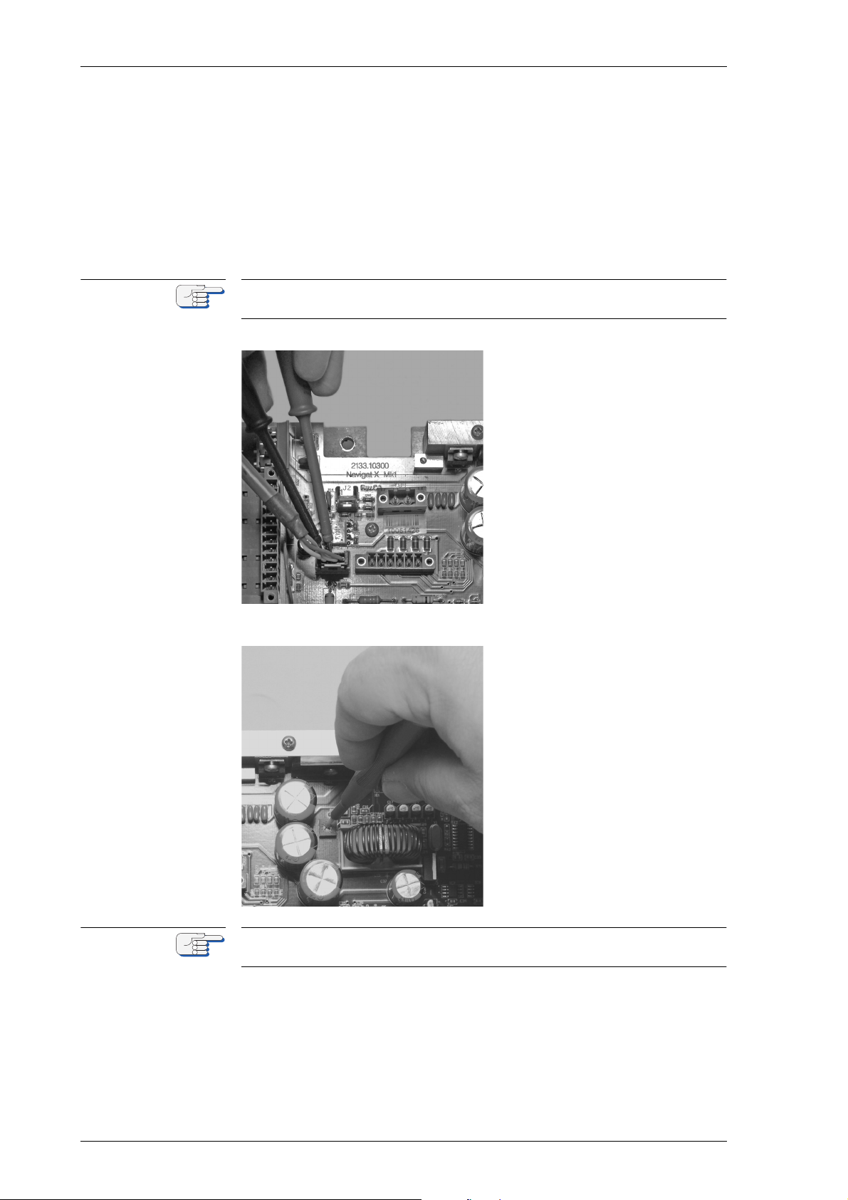
MRSPQPLc k^sfd^q u jh N
kçíÉ
kçíÉ
gain factor settings in the Technical Pages (code 140) need to
become checked and adjusted:
– Follow the instructions in ”CORRECTION VALUES” on page 8-26
of the ‘Factory Settings Menu (Technical Pages)´ to match both
gyrosphere current values.
8. In case the reconfirmed value for the gyrosphere current, directly
measured (true RMS) at the 1 Ω gyro current test resistor (R103) on
the master PCB, is as well above 320 mA, the VAC true RMS value
needs to become adjusted:
For a present operating voltage of 100 VAC on the master PCB, 105 VAC
true RMS are necessary.
cбЦмкЙ=RJOW
jЙ~лмкЙгЙен=зС=s^`
íêìÉ=ojp=~í=gQ
cбЦмкЙ=RJPW
^ЗамлнгЙен=зС=нкмЙ=ojp
~н=йзнЙенбзгЙнЙк=oPS=зе
íÜÉ=jhN=ã~ëíÉê=m`_
– Measure the VAC true RMS
at pins 1 and 2 (wires white
and brown) of the J4 connector on the NAVIGAT X
MK1 master PCB.
9. Adjust the potentiometer (R36)
on the NAVIGAT X MK1 master
PCB with a trimmer adjustment
tool to set 105 VAC true RMS.
⇒ Be careful not to damage the
potentiometer (R36).
A regular screwdriver is not recommended for the adjustment of the
potentiometer (R36) as these are sensible components.
RJNO mзпЙкJмй=cмеЕнбзе=qЙлн
Page 75
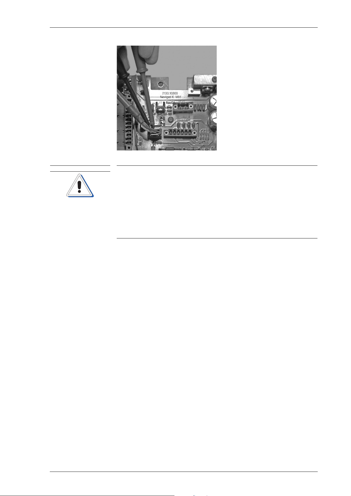
k^sfd^q u jh N MRSPQPLc
`^rqflk
cбЦмкЙ=RJQW
jЙ~лмкЙгЙен=зС=s^`
íêìÉ=ojp=~í=gQ
10. Measure again the VAC true
RMS at the pins 1 and 2 (wires
white and brown) of the J4 connector on the NAVIGAT X MK1
master PCB to check whether
105 VAC true RMS are set.
11. Repeat steps 8 – 10 if necessary
until 105 VAC true RMS are set.
Risk of defective gyrosphere
The gyrosphere may not be in operable working condition, if after a time
period of around 45 minutes after power-up the gyrosphere current has
not dropped below 320 mA.
If a visual inspection reveals no obvious cause of malfunction, the powerup cycle of the gyrosphere must be completely repeated.
If after a time period of around 45 minutes after the second power-up
cycle the gyrosphere current has still not dropped below 320 mA, the
gyrosphere may not be in operable working condition.
Contact the Sperry Marine Service for advice.
⇒ If the current is still above 320 mA, the gyrosphere may not be in
operable working condition.
12. Proceed with a visual inspection of the gyrosphere, to search any
obvious cause for malfunction, see “Gyrosphere Maintenance” in
the Installation, Maintenance and Service Procedures, 05000-0125-01
for details.
mзпЙкJмй=cмеЕнбзе=qЙлн RJNP
Page 76
MRSPQPLc k^sfd^q u jh N
kçíÉ
kçíÉ
kçíÉ
13. If a visual inspection reveals no obvious cause for malfunction,
repeat the complete power-up procedure and check again if after
around 45 minutes after the second power-up cycle the gyrosphere
current has dropped below 320 mA.
⇒ If after around 45 minutes after the second power-up cycle the cur-
rent is still above 320 mA, and no other obvious cause of malfunction is found, the gyrosphere may not be in operable working
condition:
– Contact the Sperry Marine Service for advice.
⇒ If after around 45 minutes after the second power-up cycle the gyro-
sphere current has dropped below 320 mA, the gyrosphere is in in
operable working condition.
14. Note the exact gyrosphere current value in the setup tables.
15. After a settling time of at least 4 hours, verify that the gyrocompass
has settled to the correct heading.
The 4 hours settling time for the alignment is only mandatory in case of
a first time installation of the NAVIGAT X MK 1.
To verify the gyrocompass’ heading, the actual true heading of the vessel
should be known with an accuracy of ± 0.1°.
– Check whether the setting of the shaft encoder correction value
in the Service Setup 1 of manual 056343 matches with the value
indicated on the baseplate.
– In case of a first time installation, check that the heading shows
the correct value approximately, taking into account any existing
misalignment of the gyrocompass. Then, set the alignment error
correction value in the Service Setup 1 as required, see “Alignment Error Correction” of manual 056343 for details. After the
alignment error correction value has been set, the gyrocompass
is to display the vessel's true heading with an accuracy of ± 0.5°.
– In case of maintenance or replacement of the gyrosphere, the
displayed heading should now already be accurate within ± 1.0°.
If necessary, adjust the stored alignment error correction value,
so that the gyrocompass displays the vessel's true heading with
an accuracy of ± 0.5°, see “Storing the magnetic compass heading calibration table” of manual 056343 for details.
16. In case of a regular maintenance, or if a defective gyrosphere has
been replaced, a special service setup menu must now be called up
to reset the gyrosphere operation time counter.
The access code for the setup menu to reset the gyrosphere operation
time counter is disclosed to authorized service personnel only and is not
described in this service procedures.
RJNQ mзпЙкJмй=cмеЕнбзе=qЙлн
Page 77
k^sfd^q u jh N MRSPQPLc
`^rqflk
kçíÉ
kçíÉ
a^kdbo
`^rqflk
`Ü~éíÉê=SW oЙгзо~дLfелн~дд~нбзе=зС=`згйзеЙенл
Risk of damage through unauthorized service
Only authorized service personnel is allowed to remove gyrocompass
system components from the compass housing.
Always keep to the mandatory safety requirements and the correct service work procedures to remove gyrocompass system components from
the compass housing.
This chapter describes removal and installation procedures of the
NAVIGAT X MK 1 system components. For a complete removal of all system components from the compass housing, the gyrosphere container
must be removed beforehand.
The removal and installation procedures of the gyrosphere container are
described separately in chapter ‘Preventive Maintenance´.
All CDU pictures within this chapter show the old type CDU without the
USP service interface at the back side, see “Control and display unit
(CDU) front and back view” on page 1-2 for new type details.
SKN oЙгзобеЦ=pулнЙг=`згйзеЙенл=Скзг=нЬЙ=`згй~лл=
iбСЙ=З~еЦЙк=нЬкзмЦЬ=ЙдЙЕнкбЕ~д=лЬзЕв
tЬЙе=нЬЙ=Езгй~лл=бл=ЙеЙкЦбтЙЗI=нЬЙ=ЦукзлйЬЙкЙ=зйЙк~нбеЦ=оздн~ЦЙ=зС=
NMM=s^`=]=PPT=eт=бл=йкЙлЙен=зе=нЬЙ=г~лнЙк=m`_I=нЬЙ=ЦукзлйЬЙкЙ=лмййду=
дбеЙлI=~еЗ=~Екзлл=нЬЙ=ЦукзлйЬЙкЙ=Езен~ЕнлK=
tЬЙе=нЬЙ=^`=г~бе=лмййду=бл=лпбнЕЬЙЗ=зеI=Ь~т~кЗзмл=дбСЙ=оздн~ЦЙл=~кЙ=
йкЙлЙен=~н=нЬЙ=дбеЙ=СбднЙк=~еЗ=нЬЙ=йзпЙк=нк~елСзкгЙкЫл=нЙкгбе~длK
j~вЙ=лмкЙ=нЬ~н=нЬЙ=г~бе=~еЗ=Д~Евмй=йзпЙк=лмййдбЙл=зС=нЬЙ=Езгй~лл=~кЙ=
~дп~ул=лпбнЕЬЙЗ=зСС=~еЗ=л~СЙЦм~кЗЙЗ=~Ц~белн=~ЕЕбЗЙен~д=лпбнЕЬбеЦJзе=
ДЙСзкЙ=~еу=кЙгзо~д=зк=белн~дд~нбзе=йкзЕЙЗмкЙл=зС=нЬЙ=ЦукзлйЬЙкЙ=ЕзеJ
н~беЙкK
Risk of damage of electrostatic-discharge-sensitive components
The NAVIGAT X MK 1 contains electrostatic sensitive components.
Electrostatic discharge may permanently damage components.
When servicing the NAVIGAT X MK 1, take considerable precautions to
prevent electrostatic discharge. Avoid touching any of the electronic circuitry.
m~кнлI=г~нЙкб~дл=~еЗ=нзздл=кЙимбкЙЗ
• 5 mm hex key
• 3 mm hex key
• No. 2 Phillips-head screwdriver
oЙгзобеЦ=pулнЙг=`згйзеЙенл=Скзг=нЬЙ=`згй~лл SJN
Page 78
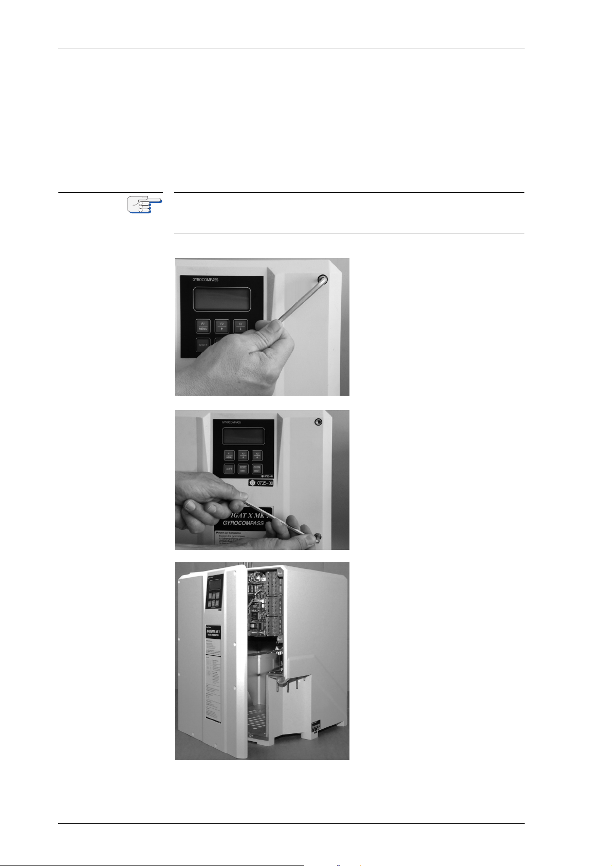
MRSPQPLc k^sfd^q u jh N
kçíÉ
mкзЕЙЗмкЙ
1. Check and note the shaft encoder correction angle and alignment
error correction values. Double check whether the shaft encoder correction angle and alignment error correction values are correctly
noted in the setup tables.
2. Make sure that the compasses main and backup power supplies are
switched off.
Take all the necessary precautions to make sure that the compasses main
and backup power supplies remain switched off during any removal and
installation procedures.
3. Unscrew the 5 mm hex-head
screws of the compass housing door.
4. Continue until all 5 mm hexhead screws are released.
5. Take off the door from the
compass housing.
SJO oЙгзобеЦ=pулнЙг=`згйзеЙенл=Скзг=нЬЙ=`згй~лл
Page 79
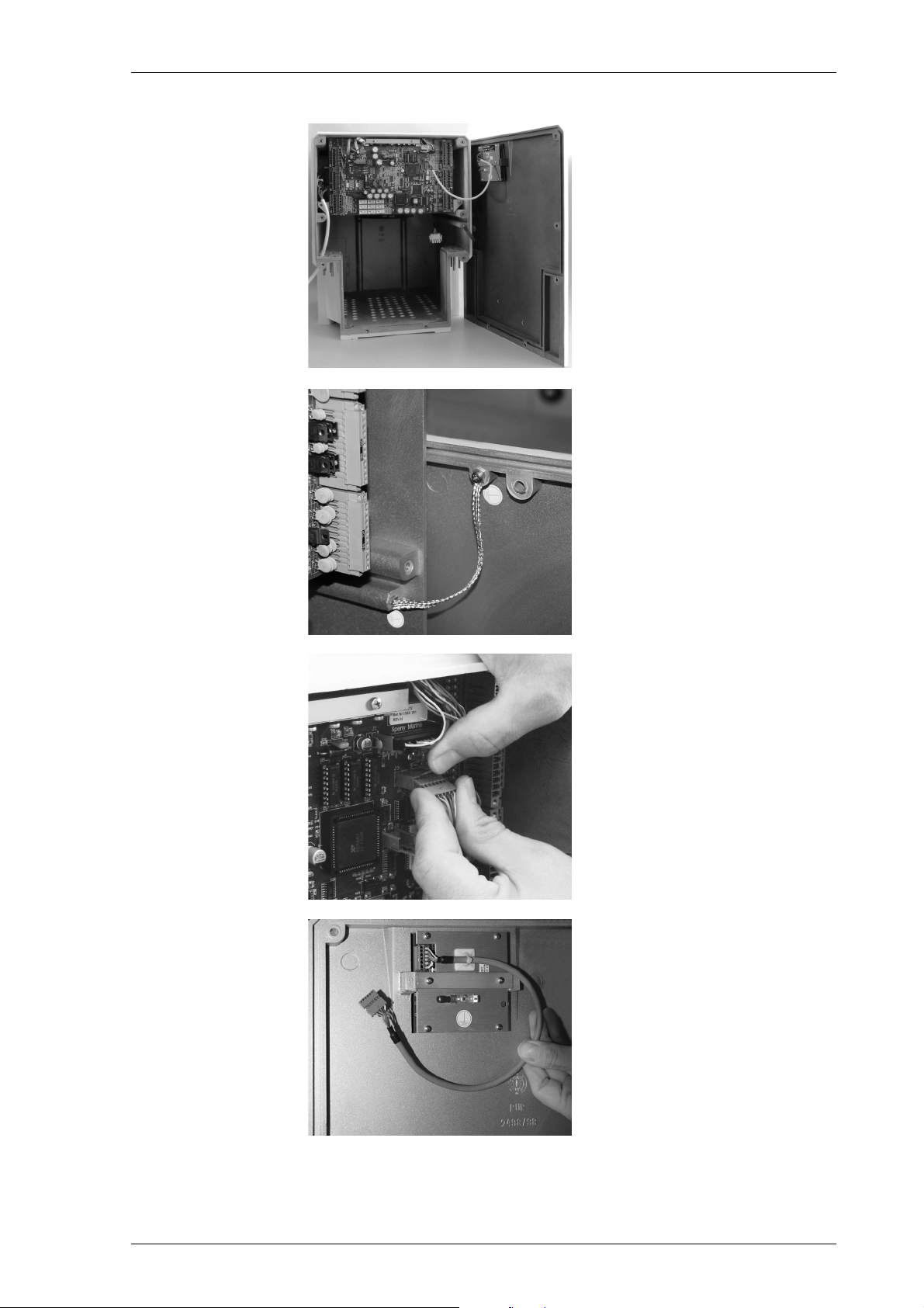
k^sfd^q u jh N MRSPQPLc
6. Place the door aside.
7. If the door is put next to the
housing, the grounding strap
may be left connected to the
compass housing.
8. Bend the retaining plate of
the J3 plug connector away
and unplug the J3 connector
of the CDU cable.
Back front of CDU with CDU
cable and released J3 connector.
oЙгзобеЦ=pулнЙг=`згйзеЙенл=Скзг=нЬЙ=`згй~лл SJP
Page 80
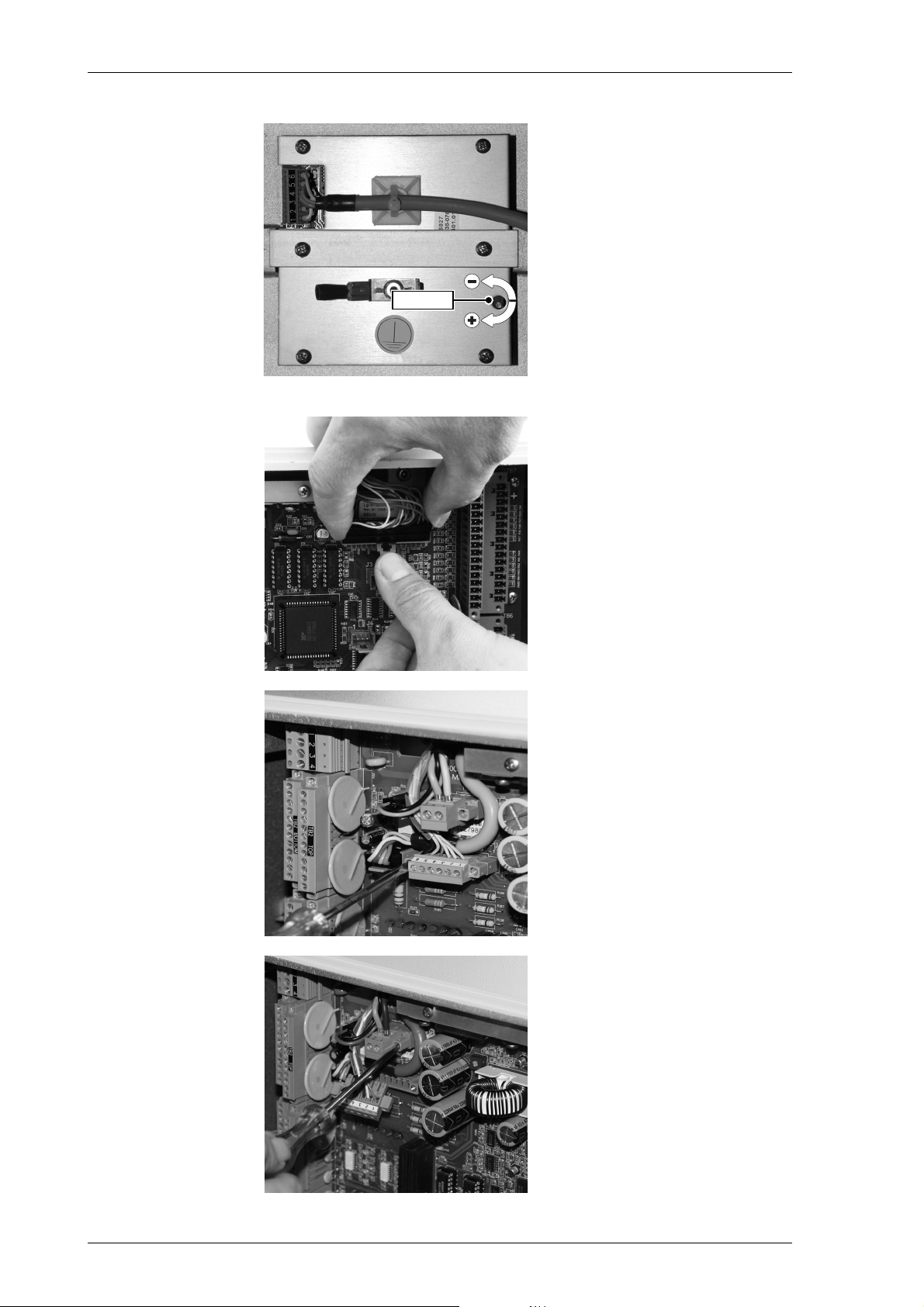
MRSPQPLc k^sfd^q u jh N
DIMMER
cбЦмкЙ=SJNW
`ar=Зблйд~у
ЗбггЙк=лЙннбеЦл
Adjacent picture shows the
dimmer settings of the CDU
display.
⇒ The new type CDU with the
additional USB service interface is shown in figure 1-2 on
page 1-2.
9. Bend the retaining plate of
the J1 plug connector away
and unplug the J1 connector
of the shaft encoder cable.
10. Unscrew the screws of the
TB 8 plug connector and
release the TB 8 plug connector of the follow-up step
motor cable.
11. Unscrew the screws of the
TB 9 plug connector and
release the TB 9 plug connector of the main power supply
transformer cable.
SJQ oЙгзобеЦ=pулнЙг=`згйзеЙенл=Скзг=нЬЙ=`згй~лл
Page 81
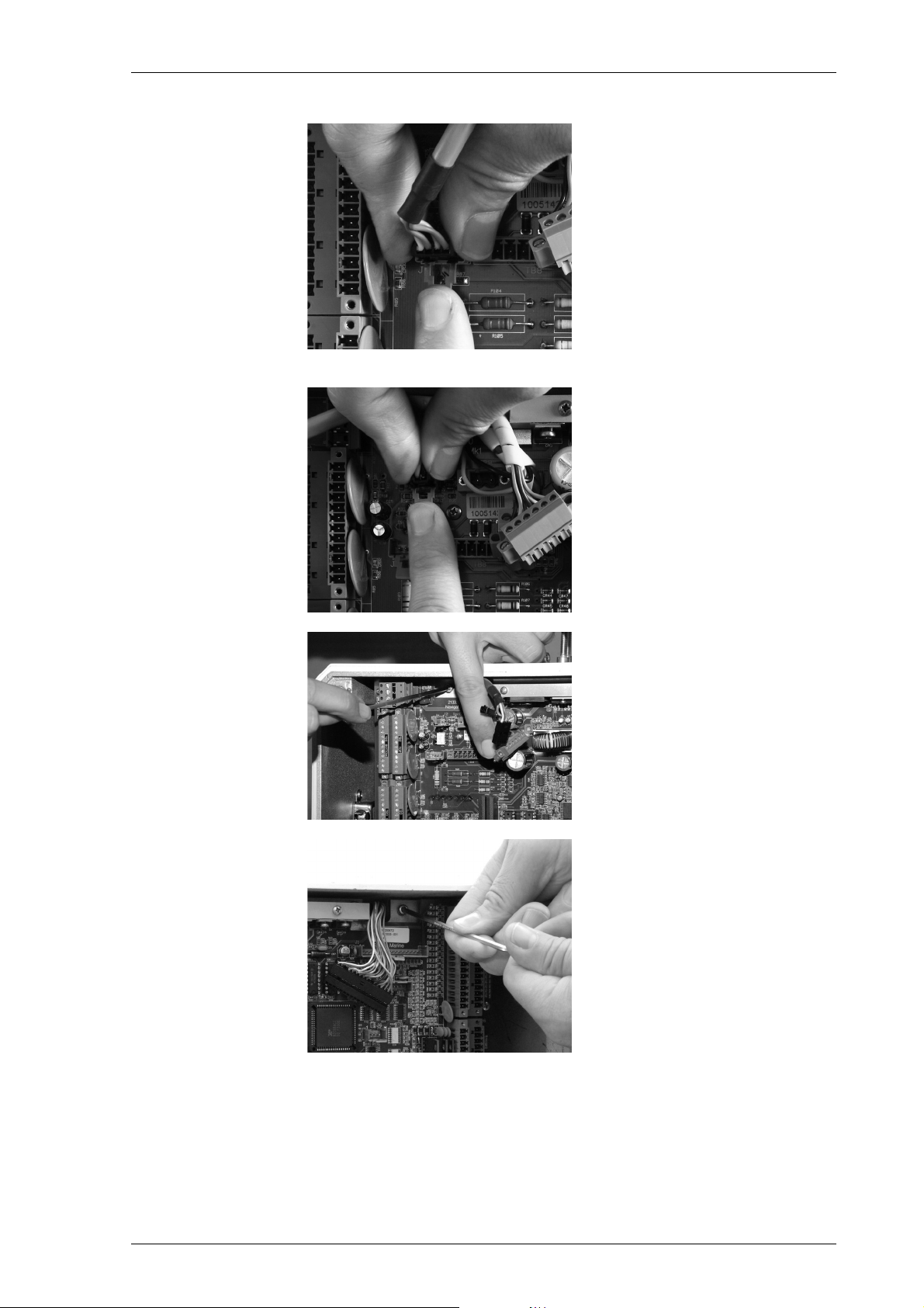
k^sfd^q u jh N MRSPQPLc
12. Bend the retaining plate of
the J4 plug connector away
and unplug the J4 connector
of the gyrosphere power supply and pick off contacts
cable.
13. Bend the retaining plate of
the J2 plug connector away
and unplug the J2 connector
of the cooling fan cable.
14. Unscrew the upper left 3 mm
hex-head screw of the master
PCB.
15. Unscrew the upper right
3 mm hex-head screw of the
master PCB.
oЙгзобеЦ=pулнЙг=`згйзеЙенл=Скзг=нЬЙ=`згй~лл SJR
Page 82
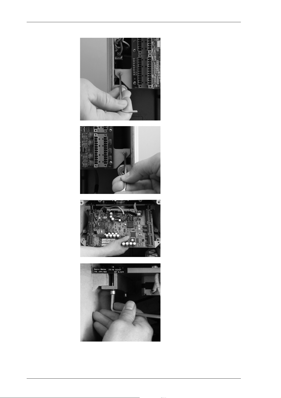
MRSPQPLc k^sfd^q u jh N
16. Unscrew the lower left 3 mm
hex-head screw of the master
PCB.
17. Unscrew the lower right
3 mm hex-head screw of the
master PCB.
⇒ Hold the master PCB with the
other hand to prevent it from
falling outside.
18. Remove the master PCB from
the compass housing.
⇒ Be careful not to damage any
connectors or cables.
19. Unscrew the front left 5 mm
hex-head screw to loosen the
left holding clamp of the
baseplate.
⇒ Do not unscrew the 5 mm hex
head screw completely.
SJS oЙгзобеЦ=pулнЙг=`згйзеЙенл=Скзг=нЬЙ=`згй~лл
Page 83
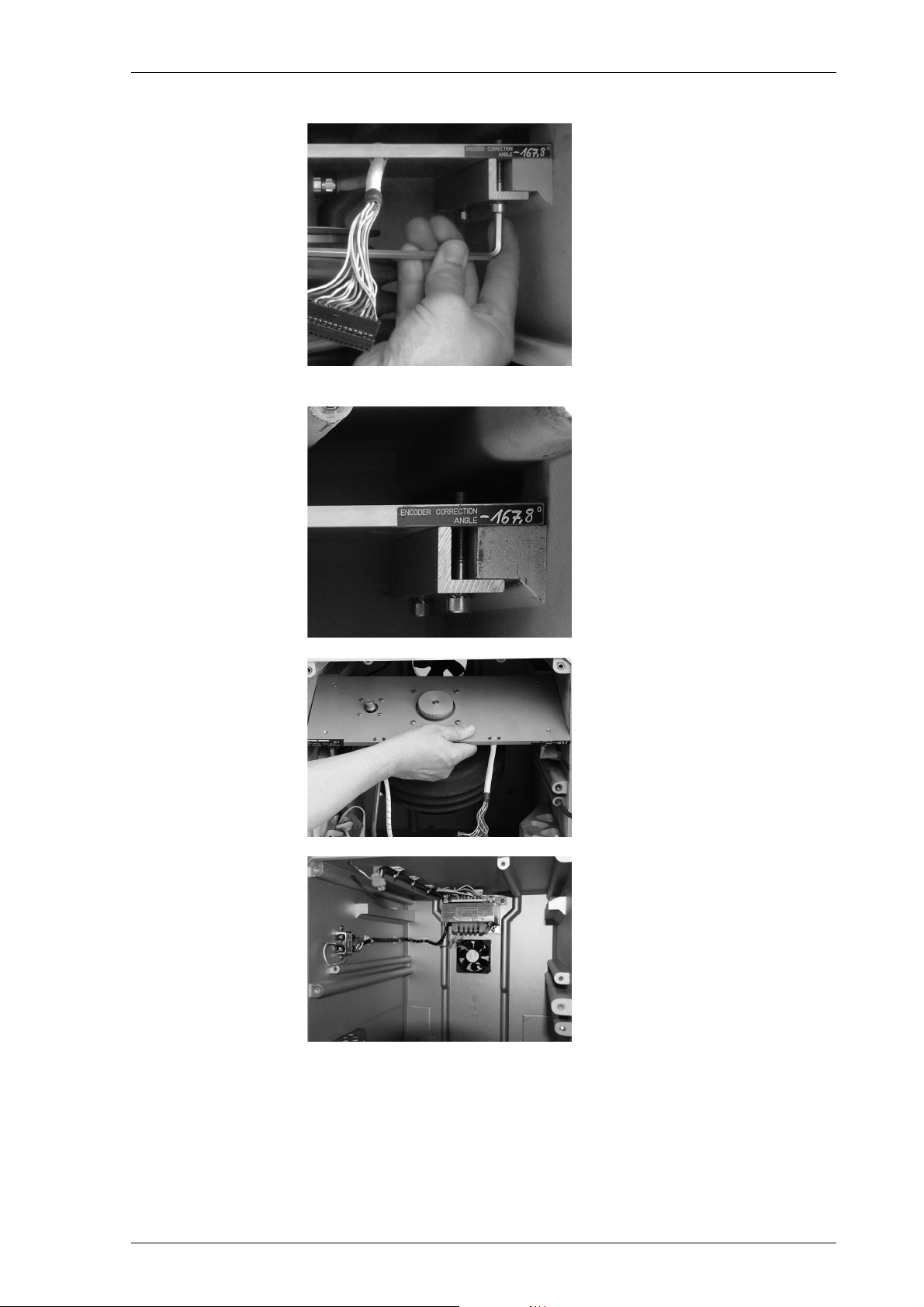
k^sfd^q u jh N MRSPQPLc
20. Unscrew the front right 5 mm
hex-head screw and continue
to unscrew the rear left and
rear right 5 mm hex-head
screws to completely loosen
the left and right holding
clamps of the baseplate.
⇒ Do not release the 5 mm hex
head screws completely.
cбЦмкЙ=SJOW
pЬ~Сн=ЙеЕзЗЙк=ЕзккЙЕнбзе
~еЦдЙ=о~дмЙ=лнбЕвЙк
Adjacent picture shows the
shaft encoder correction
angle value sticker placed at
the right front corner of the
baseplate.
21. Remove the baseplate with
the gyrosphere suspension
carefully from the compass
housing.
Adjacent picture shows the
empty compass housing with
the main power supply transformer and cooling fan on the
rear side.
oЙгзобеЦ=pулнЙг=`згйзеЙенл=Скзг=нЬЙ=`згй~лл SJT
Page 84
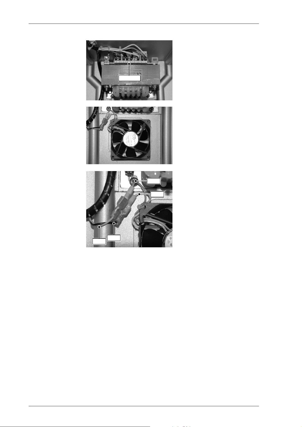
MRSPQPLc k^sfd^q u jh N
Wire Link
Red
Blue
Red
Black
The main power supply transformer with default wire link
set for 230 VAC power supply.
⇒ For details of the power sup-
ply wire link settings, see
Figure 7-1 on page 7-4.
The cooling fan with J2 cable
connection.
Details of the cooling fan / J2
cable connection:
– Red / Red
– Blue / Black
SJU oЙгзобеЦ=pулнЙг=`згйзеЙенл=Скзг=нЬЙ=`згй~лл
Page 85
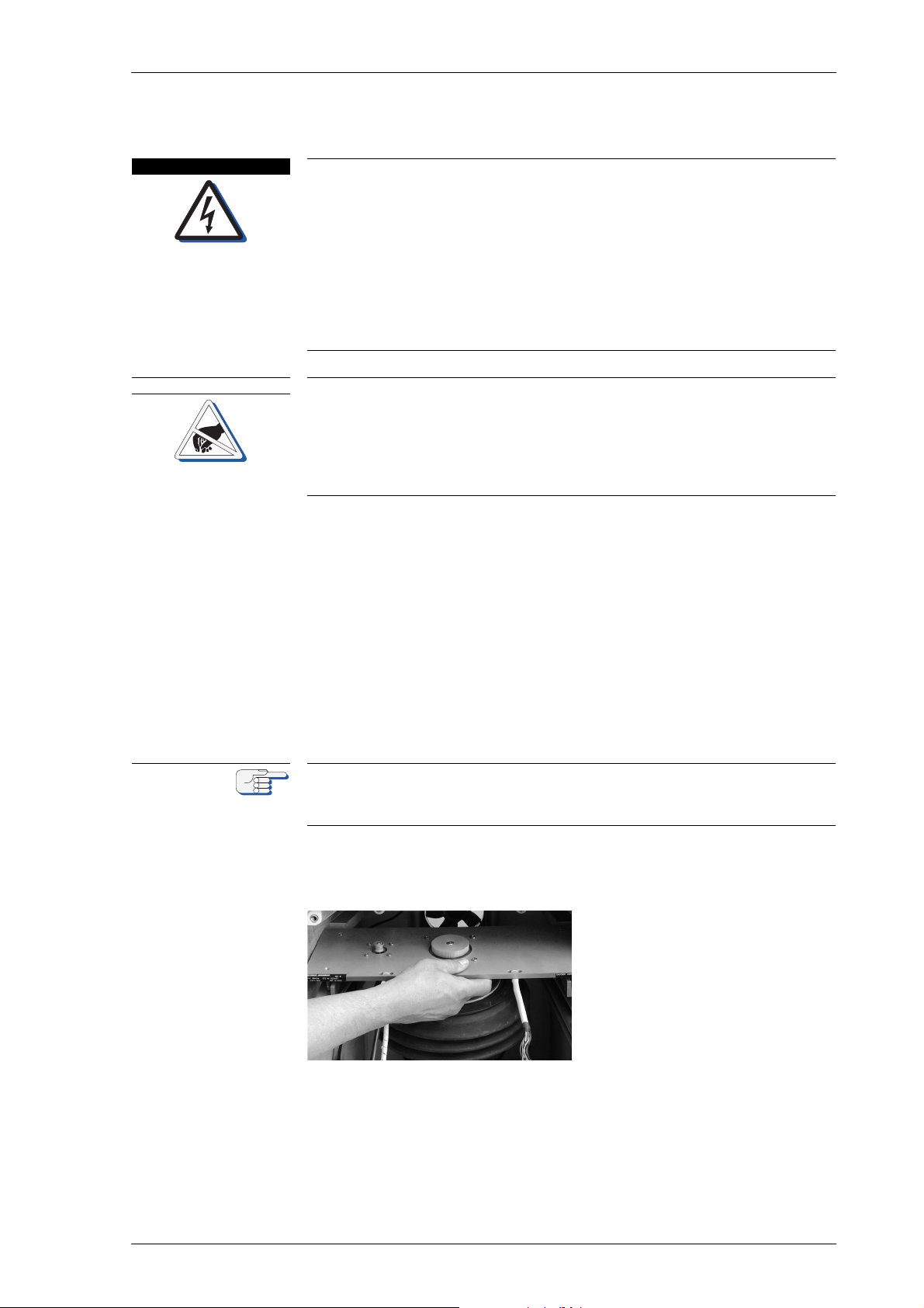
k^sfd^q u jh N MRSPQPLc
a^kdbo
`^rqflk
kçíÉ
SKO fелн~ддбеЦ=pулнЙг=`згйзеЙенл=бенз=нЬЙ=`згй~лл
iбСЙ=З~еЦЙк=нЬкзмЦЬ=ЙдЙЕнкбЕ~д=лЬзЕв
tЬЙе=нЬЙ=Езгй~лл=бл=ЙеЙкЦбтЙЗI=нЬЙ=ЦукзлйЬЙкЙ=зйЙк~нбеЦ=оздн~ЦЙ=зС=
NMM=s^`=]=PPT=eт=бл=йкЙлЙен=зе=нЬЙ=г~лнЙк=m`_I=нЬЙ=ЦукзлйЬЙкЙ=лмййду=
дбеЙлI=~еЗ=~Екзлл=нЬЙ=ЦукзлйЬЙкЙ=Езен~ЕнлK=
tЬЙе=нЬЙ=^`=г~бе=лмййду=бл=лпбнЕЬЙЗ=зеI=Ь~т~кЗзмл=дбСЙ=оздн~ЦЙл=~кЙ=
йкЙлЙен=~н=нЬЙ=дбеЙ=СбднЙк=~еЗ=нЬЙ=йзпЙк=нк~елСзкгЙкЫл=нЙкгбе~длK
j~вЙ=лмкЙ=нЬ~н=нЬЙ=г~бе=~еЗ=Д~Евмй=йзпЙк=лмййдбЙл=зС=нЬЙ=Езгй~лл=~кЙ=
~дп~ул=лпбнЕЬЙЗ=зСС=~еЗ=л~СЙЦм~кЗЙЗ=~Ц~белн=~ЕЕбЗЙен~д=лпбнЕЬбеЦJзе=
ДЙСзкЙ=~еу=кЙгзо~д=зк=белн~дд~нбзе=йкзЕЙЗмкЙл=зС=нЬЙ=ЦукзлйЬЙкЙ=ЕзеJ
н~беЙкK
Risk of damage of electrostatic-discharge-sensitive components
The NAVIGAT X MK 1 contains electrostatic sensitive components.
Electrostatic discharge may permanently damage components.
When servicing the NAVIGAT X MK 1, take considerable precautions to
prevent electrostatic discharge. Avoid touching any of the electronic circuitry.
m~кнлI=г~нЙкб~дл=~еЗ=нзздл=кЙимбкЙЗ
• 5 mm hex key
• 3 mm hex key
• No. 2 Phillips-head screwdriver
mкзЕЙЗмкЙ
1. Make sure that the compasses main and backup power supplies are
switched off.
Take all the necessary precautions to make sure that the compasses main
and backup power supplies remain switched off during any removal and
installation procedures.
2. Insert the baseplate with the
gyrosphere suspension carefully into the compass housing.
⇒ In case the baseplate does not
smoothly slide in, readjust the
hex-head screws that the
holding clamps have enough
clearance.
fелн~ддбеЦ=pулнЙг=`згйзеЙенл=бенз=нЬЙ=`згй~лл SJV
Page 86
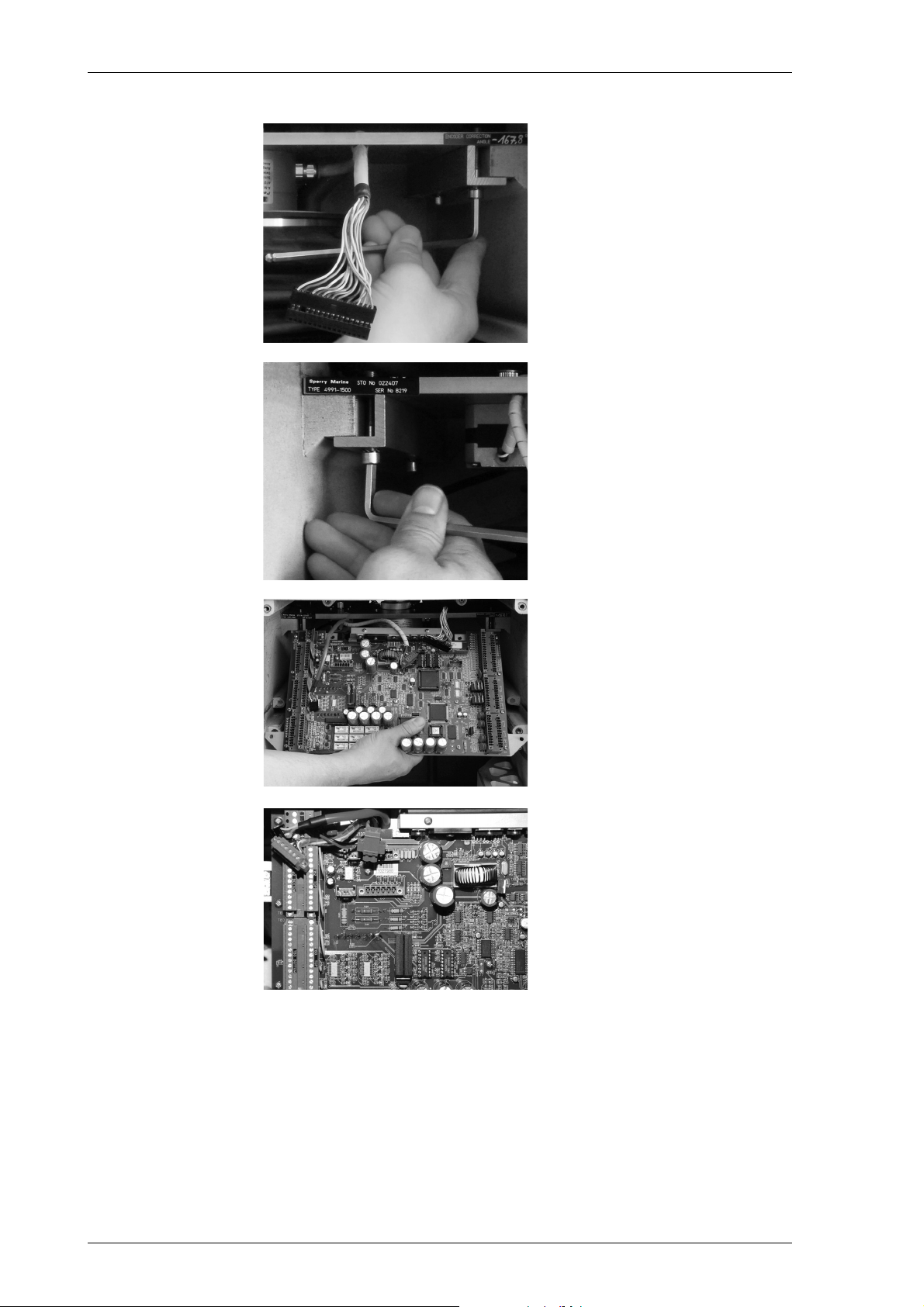
MRSPQPLc k^sfd^q u jh N
3. Tighten the front right 5 mm
hex-head screw.
4. Tighten the front left 5 mm
hex-head screw and continue
to tighten the rear left and
rear right 5 mm hex-head
screws to completely secure
the left and right holding
clamps of the baseplate.
5. Insert the master PCB carefully into the compass housing.
⇒ Place all cables in the cut-outs
of the master PCB to not damage any connectors or cables.
Adjacent picture shows the
cables fed through the left
cut-out of the master PCB.
SJNM fелн~ддбеЦ=pулнЙг=`згйзеЙенл=бенз=нЬЙ=`згй~лл
Page 87
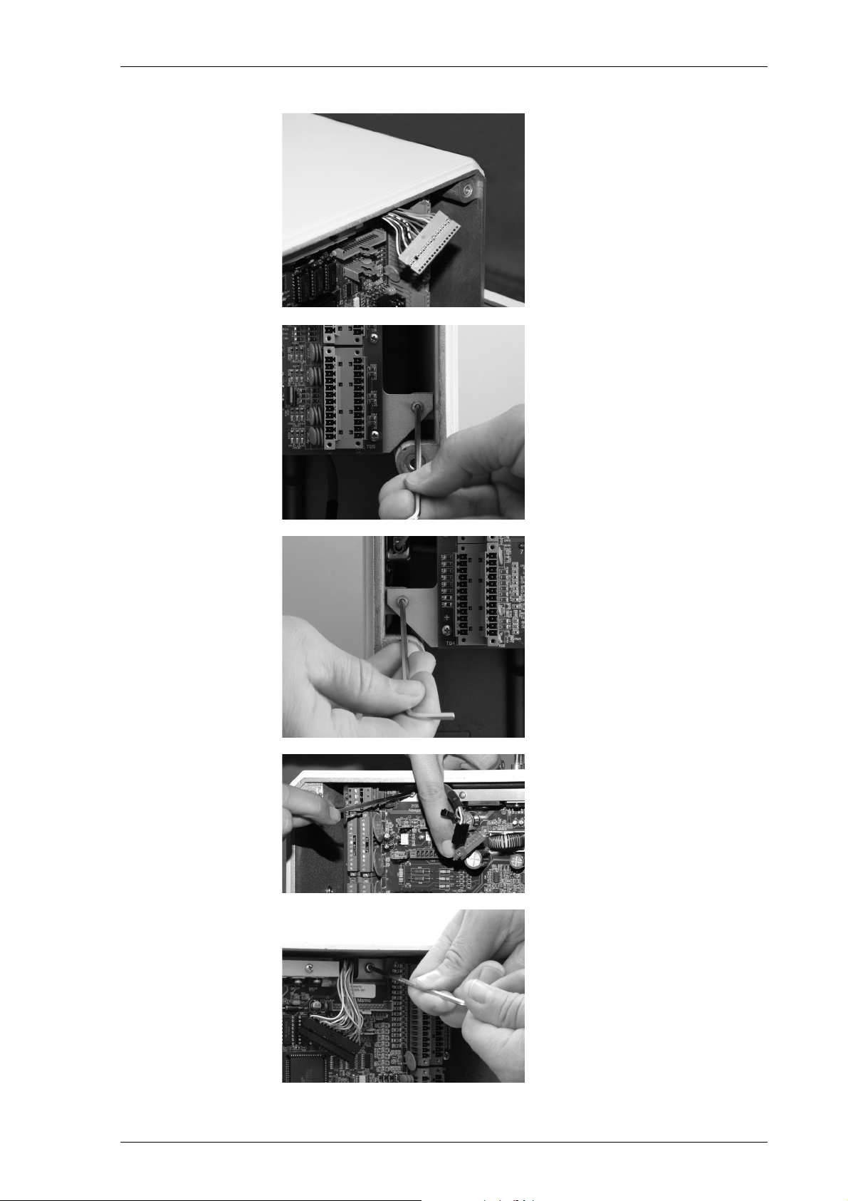
k^sfd^q u jh N MRSPQPLc
Adjacent picture shows the
cables fed through the right
cut-out of the master PCB.
6. Hold the master PCB with one
hand to prevent it from falling
out.
7. Tighten the lower right 3 mm
hex-head screw of the master
PCB.
8. Tighten the lower left 3 mm
hex-head screw of the master
PCB.
9. Tighten the upper left 3 mm
hex-head screw of the master
PCB.
10. Tighten the upper right 3 mm
hex-head screw of the master
PCB.
fелн~ддбеЦ=pулнЙг=`згйзеЙенл=бенз=нЬЙ=`згй~лл SJNN
Page 88
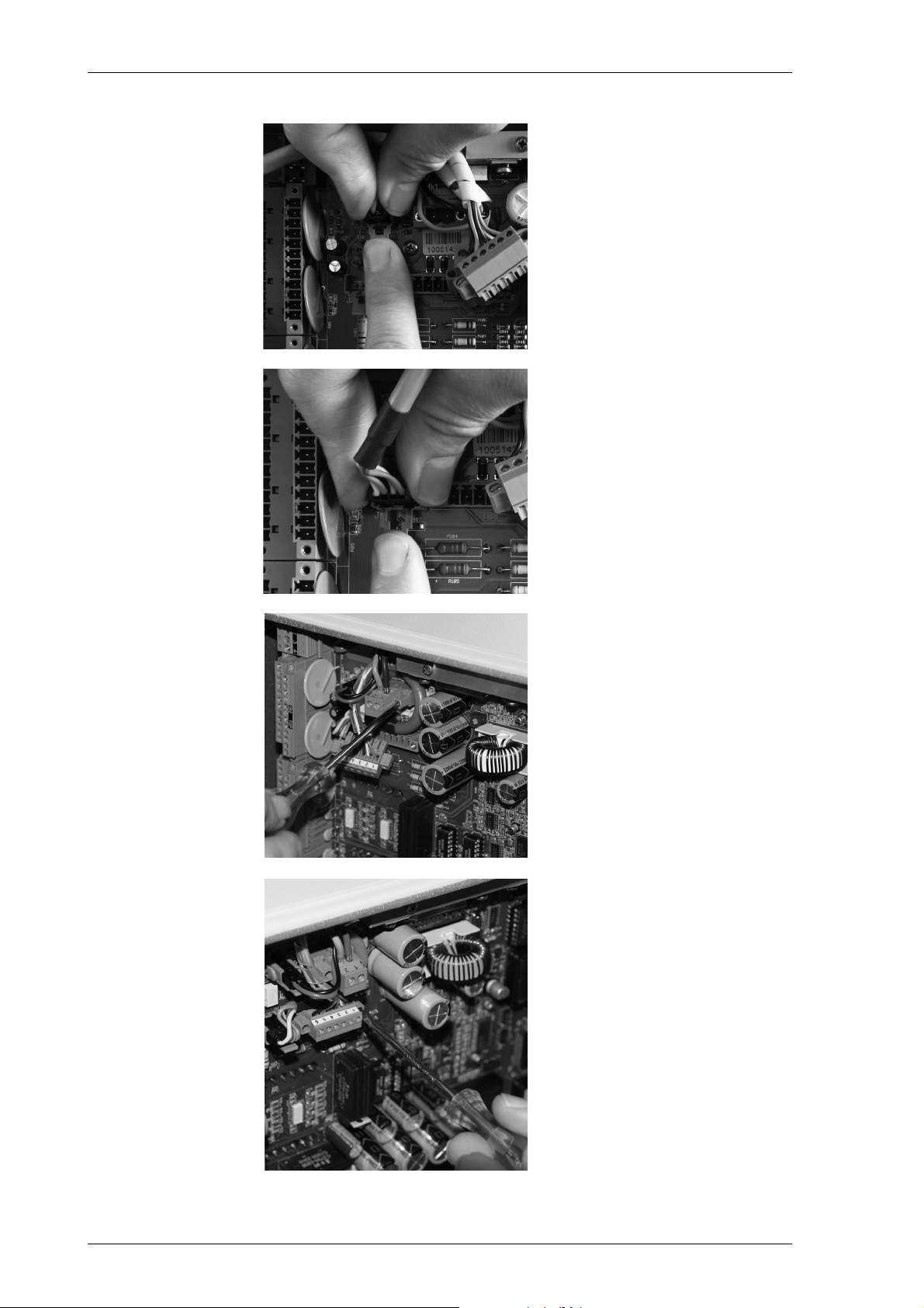
MRSPQPLc k^sfd^q u jh N
11. Bend the retaining plate of
the J2 plug connector away
and plug in the J2 connector.
12. Bend the retaining plate of
the J4 plug connector away
and plug in the J4 connector.
13. Plug in the TB 9 plug connector and tighten the screws of
the TB 9 plug connector.
14. Plug in the TB 8 plug connector and tighten the screws of
the TB 8 plug connector.
SJNO fелн~ддбеЦ=pулнЙг=`згйзеЙенл=бенз=нЬЙ=`згй~лл
Page 89
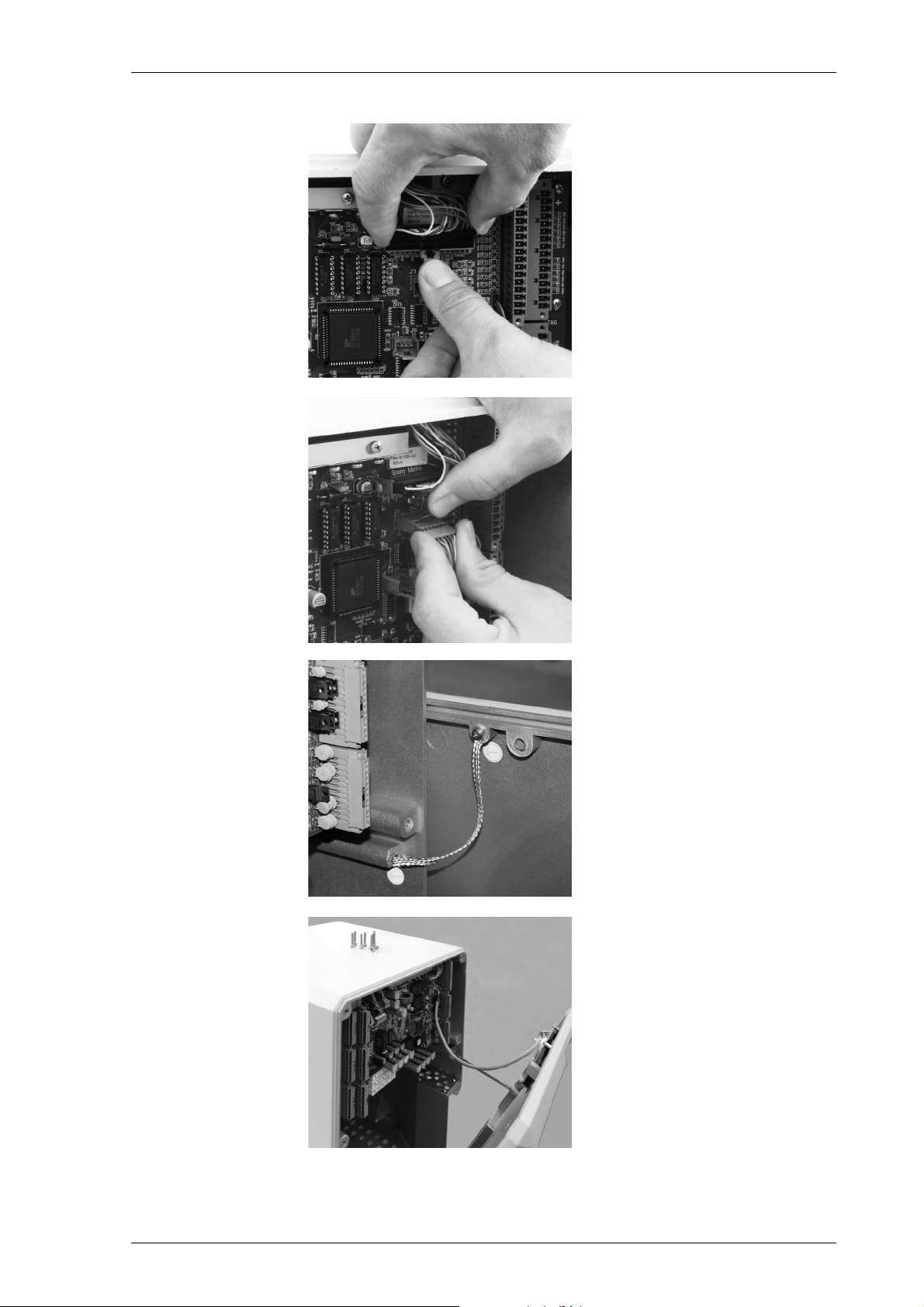
k^sfd^q u jh N MRSPQPLc
15. Bend the retaining plate of
the J1 plug connector away
and plug in the J1 connector.
16. Bend the retaining plate of
the J3 plug connector away
and plug in the J3 connector
of the CDU cable.
17. If previously removed, reconnect the grounding strap to
the compass housing.
18. Place the door in front of the
compass housing and close
the door.
fелн~ддбеЦ=pулнЙг=`згйзеЙенл=бенз=нЬЙ=`згй~лл SJNP
Page 90
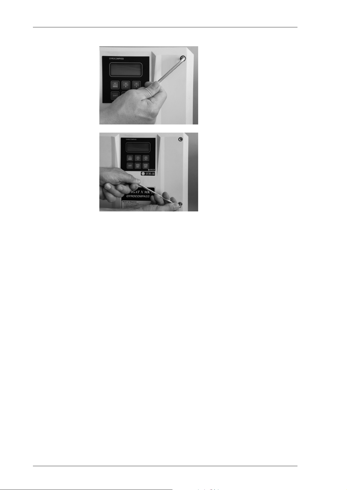
MRSPQPLc k^sfd^q u jh N
19. Tighten the 5 mm hex-head
screws of the compass housing door.
20. Continue until all 5 mm hexhead screws are tightened.
SJNQ fелн~ддбеЦ=pулнЙг=`згйзеЙенл=бенз=нЬЙ=`згй~лл
Page 91

k^sfd^q u jh N MRSPQPLc
`Ü~éíÉê=TW pулнЙг=fелн~дд~нбзе
TKN fелн~дд~нбзе=oЙЕзггЙеЗ~нбзел
The compact, space saving and low weight single unit design of the
NAVIGAT X MK 1 gyrocompass allows it to become installed at virtually
any location on board and on any bridge.
However, certain recommendations regarding environmental and
installing conditions exist, to enable best performance of the
NAVIGAT X MK 1 system; for the required environmental conditions, see
”General Safety Information for Service Personnel” and ”Environmental
Requirements” on page 1-13 for details.
mä~ÅÉ=çÑ=fåëí~ää~íáçå
The gyrocompass must be installed on a stable, level foundation.
In the horizontal plane, a maximum tilt of the compass housing relative
to the vessel´s X and Y axes of ± 3° is accepted.
The compass housing may be installed amidship, port or starboard. An
installing position midships respectively near to keel line is always preferable if possible.
The compass housing may be installed forward, aftwards or midships.
An installing position midships respectively near to the Center of Gravity (CoG) is always preferable if possible.
sЙенбд~нбзе=L=qЙгйЙк~нмкЙ
At the installing location of the compass, adequate ventilation must be
ensured. Air conditioning at installing location may be advisable to
ensure operation of the gyrocompass within ambient temperature range
/ recommended operational temperature for highest system longevity,
see also ”Temperature Conditions” on page 1-13.
bдЙЕнкзг~ЦеЙнбЕ=fенЙкСЙкЙеЕЙ
The gyrocompass is a highly precise electronic device and accuracies
will suffer in case of electromagnetic interference of other electrical
devices. All electromagnetic interference clearances must therefore
always be followed accurately to ensure trouble free operation of the
NAVIGAT X MK 1 system, see also ”Electromagnetic Compatibility
(EMC) / Electromagnetic Interference” on page 1-14 for details.
fелн~дд~нбзе=oЙЕзггЙеЗ~нбзел TJN
Page 92

MRSPQPLc k^sfd^q u jh N
sáÄê~íáçå
The gyrocompass is designed to work trouble free in Area A classified
locations according to Germanischer Lloyd vibration level classification,
see also ”Vibration” on page 1-14 for details.
The gyrocompass will show best operational performance if minimal
vibration levels are kept at place of installation.
Installing the gyrocompass in the engine room is not recommended and
should always be avoided if possible, as engine rooms are usually classified as Area B location, according to Germanischer Lloyd vibration
level classification.
An installing position directly on the vessel´s deck structure is always
preferable to minimise possible vibration levels.
TJO fелн~дд~нбзе=oЙЕзггЙеЗ~нбзел
Page 93
k^sfd^q u jh N MRSPQPLc
`^rqflk
`^rqflk
TKO jÉÅÜ~åáÅ~ä=fåëí~ää~íáçå
qк~елйзкнбеЦ=нЬЙ=`згй~лл=eзмлбеЦ
Risk of damage to the gyrosphere
The gyrosphere is always to be transported in its carrying box in the original transport container.
Do not throw or drop the transport container.
The transport container is to be transported in an upright position only.
Risk of damage to the gyrosphere
Carry the carrying box containing the gyrosphere by hand only and handle it with extreme care.
Remove the gyroshpere from the carrying box only if required for immediate installation.
The NAVIGAT X MK 1 gyrocompass system when delivered comprises
the NAVIGAT X MK 1 compass housing complete with installed base
plate assembly, stock no. 022407, and master PCB, stock no. 020672,
the gyrosphere container, stock no. 022561,
the gyrosphere, stock no. 074829,
and the installation and replacement parts kit, stock no. 022638.
The gyrosphere is contained in a specially designed transport box. This
transport box is completely suitable for transport purposes by air, sea,
rail and road.
Until installation, the gyrosphere is always to be stored in its original
transport box. Upon installation, the gyrosphere is to be removed from
the transport box and is to be carried by hand directly to the place of
installation.
fелн~ддбеЦ=нЬЙ=`згй~лл=eзмлбеЦ
For the installation of the gyrocompass all installing recommendations
and environmental requirements are to be followed, see “Environmental Requirements” on page 1-13 and ”Installing Recommendations” on
page 7-1 for details.
The compass housing is to be attached to a level surface, e.g. a floor or
console base by means of six M10 bolts or welding studs (to be supplied
by the shipyard). Sufficient space around the gyrocompass for the housing to be opened and maintenance work to be carried out must be
ensured. For the amount of space required, the attachment points and
the position of the cable inlets, refer to dimension drawing 4914-0112-02
in the appendix.
In the horizontal plane, the compass may be installed at any angle with
respect to the vessel‘s longitudinal axis and the alignment error (i.e. the
angle between the compass‘ and the vessel‘s longitudinal axis) is corrected electronically by setting the alignment error correction value in
the Service Setup 1, see “Configuration Menu - Service Setup 1” on
page 8-1 for details.
jÉÅÜ~åáÅ~ä=fåëí~ää~íáçå TJP
Page 94
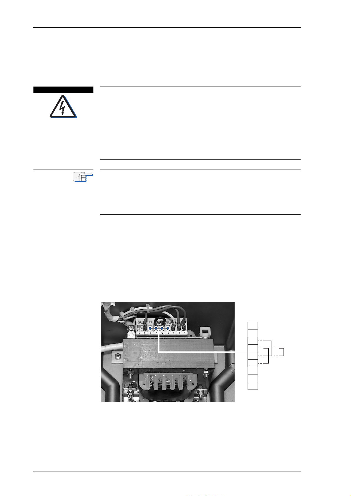
MRSPQPLc k^sfd^q u jh N
a^kdbo
kçíÉ
3
5
6
8
9
230 VAC
11 5 VAC
1
2
4
7
TKP bдЙЕнкбЕ~д=fелн~дд~нбзе
^`=pмййду=mзпЙк=`зеСбЦмк~нбзе
iбСЙ=З~еЦЙк=нЬкзмЦЬ=ЙдЙЕнкбЕ~д=лЬзЕв
tЬЙе=нЬЙ=^`=г~бе=лмййду=бл=лпбнЕЬЙЗ=зеI=дбоЙ=оздн~ЦЙл=~кЙ=йкЙлЙен=~н=нЬЙ=
дбеЙ=СбднЙк=~еЗ=нЬЙ=йзпЙк=нк~елСзкгЙкЫл=нЙкгбе~длK
tЬЙе=нЬЙ=Езгй~лл=бл=ЙеЙкЦбтЙЗ=Eг~бе=~еЗLзк=Д~Евмй=лмййду=йкЙлЙенFI=
нЬЙ=ЦукзлйЬЙкЙ=зйЙк~нбеЦ=оздн~ЦЙ=зС=NMM=s^`=]=PPT=eт=бл=йкЙлЙен=зе=нЬЙ=
г~лнЙк=m`_I=нЬЙ=ЦукзлйЬЙкЙ=лмййду=дбеЙл=~еЗ=~Екзлл=нЬЙ=ЦукзлйЬЙкЙ=ЕзеJ
н~ЕнлK
j~вЙ=лмкЙ=нЬЙ=Езгй~ллD=г~бе=~еЗ=Д~Евмй=йзпЙк=лмййдбЙл=~кЙ=~дп~ул=
лпбнЕЬЙЗ=зСС=~еЗ=л~СЙЦм~кЗЙЗ=~Ц~белн=~ЕЕбЗЙен~д=лпбнЕЬбеЦJзе=пЬЙе=
ЕзеСбЦмкбеЦ=нЬЙ=лулнЙг=Сзк=нЬЙ=оЙллЙдЫл=^`=лмййду=оздн~ЦЙI
This Operation, Installation and Service Manual 056343 applies only for
NAVIGAT X MK 1 systems with the new type master PCB and the PCB
transformer on the rear side.
For NAVIGAT X MK 1 systems with the old type master PCB and the PCB
transformer on the front side, only the Operation, Installation and Service
Manual 056310 is applicable.
cбЦмкЙ=TJNW
^`=лмййду=йзпЙк
ЕзеСбЦмк~нбзе=нЙкгбе~дл
The NAVIGAT X MK 1 main power supply transformer in the compass
housing is delivered pre wired for 230 VAC power supply with a wire
link connecting the transformer terminals 5 to 6, as shown in Figure 7-1.
If the system is required to operate on 115 VAC power supply, wire links
must be installed to link the transformer terminals 4 to 6 and 5 to 7.
To gain access to the main power supply transformer, the master PCB
and the baseplate must be temporarily removed from the compass
housing, see “Removing System Components from the Compass” on
page 6-1 for details.
Figure 7-1 shows the default wire link set for the 230 VAC power supply.
TJQ bдЙЕнкбЕ~д=fелн~дд~нбзе
Page 95
k^sfd^q u jh N MRSPQPLc
a^kdbo
`^rqflk
`^rqflk
kçíÉ
tбкбеЦ=rй=нЬЙ=pулнЙг
iбСЙ=З~еЦЙк=нЬкзмЦЬ=ЙдЙЕнкбЕ~д=лЬзЕв
tЬЙе=нЬЙ=^`=г~бе=лмййду=бл=лпбнЕЬЙЗ=зеI=дбоЙ=оздн~ЦЙл=~кЙ=йкЙлЙен=~н=нЬЙ=
дбеЙ=СбднЙк=~еЗ=нЬЙ=йзпЙк=нк~елСзкгЙкЫл=нЙкгбе~длK
tЬЙе=нЬЙ=Езгй~лл=бл=ЙеЙкЦбтЙЗ=Eг~бе=~еЗLзк=Д~Евмй=лмййду=йкЙлЙенFI=
нЬЙ=ЦукзлйЬЙкЙ=зйЙк~нбеЦ=оздн~ЦЙ=зС=NMM=s^`=]=PPT=eт=бл=йкЙлЙен=зе=нЬЙ=
г~лнЙк=m`_I=нЬЙ=ЦукзлйЬЙкЙ=лмййду=дбеЙл=~еЗ=~Екзлл=нЬЙ=ЦукзлйЬЙкЙ=ЕзеJ
н~ЕнлK
j~вЙ=лмкЙ=нЬЙ=Езгй~ллD=г~бе=~еЗ=Д~Евмй=йзпЙк=лмййдбЙл=~кЙ=~дп~ул=
лпбнЕЬЙЗ=зСС=~еЗ=л~СЙЦм~кЗЙЗ=~Ц~белн=~ЕЕбЗЙен~д=лпбнЕЬбеЦJзе=пЬЙе=
ЕзеСбЦмкбеЦ=нЬЙ=лулнЙг=Сзк=нЬЙ=оЙллЙдЫл=^`=лмййду=оздн~ЦЙI
Risk of malfunction through wrong wiring
Wrong wiring, especially as running wires from one side of the compass
housing to the other or across the master PCB will cause malfunction.
Always use the cable inlets on both sides of the compass housing for
accurate wiring and keep all wires running inside the housing as short as
possible.
Always avoid to run wires from one side of the compass housing across
to the other.
Risk of earth faults
Wrong wiring of the cable shields makes the cables act as antennas
resulting in earth faults.
Always make sure to correctly draw back the cable shields and fasten the
cables to avoid earth faults.
In case of earth faults, it is recommended to always check first the cable
wiring for correctly connected cable shields.
Wire up the system according to the standard connection diagrams and
other relevant documents provided in the appendix.
If installation-specific connection diagrams have been provided for a
given system, these supersede any connection information contained in
standard connection diagrams.
Ship's cables are directly connected to screw-down terminals on the
master PCB.
Insert the ship's cables through the inlets at the sides of the compass
housing. Remove the outer cable covers, draw back the cable shields
and fasten the cables with clamps or tie-wraps to the threaded studs of
the inlet plates. Refer to dimension drawing 4914-0112-02 in the appendix.
Route the wires connecting to TB1 – TB4 through the inlets on the left
hand side of the housing.
Route the wires connecting to TB5 – TB7 through the inlets on the right
hand side.
bдЙЕнкбЕ~д=fелн~дд~нбзе TJR
Page 96

MRSPQPLc k^sfd^q u jh N
`^rqflk
kçíÉ
TKQ dукзлйЬЙкЙ=fелн~дд~нбзе
Risk of damage through unauthorized service
Any service and installation work on the gyrosphere is to be carried out
by authorized service personnel only.
Never undertake service or installation work if unskilled for the certain
procedure.
When the compass housing has been mounted and the system is wired
up so far that supply power is available, procedures should continue
with the installation of the gyrosphere into the gyrosphere container
and the mounting of the assembled container in the compass.
Alternatively, the installer may wire up the system completely and carry
out the initial system configuration before the gyrosphere is installed.
For installation and service procedures of the gyrosphere and gyrosphere container, the following separate Installation, Maintenance and
Service Procedures, delivered with the gyrosphere, apply:
- 04911-0125-001, for gyrosphere type 2, gyrosphere container mod. 7/2
- 04911-0125-002, for gyrosphere type 2, gyrosphere container mod. 10/2
- 05000-0125-001, for gyrosphere type 3, gyrosphere container mod. 10/3
- 05000-0125-002, for gyrosphere type 3, gyrosphere container mod. 10/3
with the NAVIGAT X MK 1 in DP vessel application.
TJS dукзлйЬЙкЙ=fелн~дд~нбзе
Page 97
k^sfd^q u jh N MRSPQPLc
a^kdbo
kçíÉ
TKR fебнб~д=pулнЙг=`зеСбЦмк~нбзе
To make the system fully functional, the configuration parameters need
to be set to the required values in the Service Setup 1, see “Configuration Menu - Service Setup 1” on page 8-1.
Additionally, the applicable standard operational settings should be
entered in the Manual Settings menu.
If a magnetic compass heading source is connected to the
NAVIGAT X MK 1 system, the magnetic compass calibration procedure
should be carried out during a sea trial, as described under ”Magnetic
Compass Calibration” on page 7-10.
`зеСбЦмк~нбзе=зС=нЬЙ=pулнЙг
iбСЙ=З~еЦЙк=нЬкзмЦЬ=ЙдЙЕнкбЕ~д=лЬзЕв
tЬЙе=нЬЙ=Езгй~лл=бл=ЙеЙкЦбтЙЗI=нЬЙ=ЦукзлйЬЙкЙ=зйЙк~нбеЦ=оздн~ЦЙ=зС=
NMM=s^`=]=PPT=eт=бл=йкЙлЙен=зе=нЬЙ=г~лнЙк=m`_I=нЬЙ=ЦукзлйЬЙкЙ=лмййду=
дбеЙл=~еЗ=~Екзлл=нЬЙ=ЦукзлйЬЙкЙ=Езен~ЕнлK=
tЬЙе=нЬЙ=^`=г~бе=лмййду=бл=лпбнЕЬЙЗ=зеI=Ь~т~кЗзмл=дбСЙ=оздн~ЦЙл=~кЙ=
йкЙлЙен=~н=нЬЙ=дбеЙ=СбднЙк=~еЗ=нЬЙ=йзпЙк=нк~елСзкгЙкЫл=нЙкгбе~длK
_Й=ЙснкЙгЙду=Е~кЙСмд=пЬЙе=зйЙк~нбеЦ=нЬЙ=Езгй~лл=пЬбдЙ=нЬЙ=ЬзмлбеЦ=бл=
зйЙеK=aз=езн=нзмЕЬ=нЬЙ=г~лнЙк=m`_I=нЬЙ=ЕзееЙЕнбеЦ=Е~ДдЙл=нз=нЬЙ=ЦукзJ
лйЬЙкЙ=Езен~беЙк=зк=~еу=знЬЙк=ЕзеЗмЕнбоЙ=ЕзгйзеЙенл=зе=нЬЙ=Езен~беЙк=
зк=бе=нЬЙ=Езгй~лл=ЬзмлбеЦK
^дп~ул=ЙсЕдмЗЙ=~еу=Езен~Ен=нз=ЙеЙкЦбтЙЗ=ЕзгйзеЙенлK
1. Check that the wiring has been carried out completely. All devices
connected to data or signal in- and outputs should be operative.
2. Energize the system at the vessel's switch and fuse unit.
A startup message is displayed and the initial self test is executed.
If the initial system configuration is carried out before the installation of
the gyrosphere, the system will raise a „gyro failure“ alarm at power-up.
The alarm may be safely acknowledged at this point to continue with the
initial configuration.
3. Go to the ”Configuration Menu - Service Setup 1” on page 8-1.
4. Select the required system type and heading reference selection settings.
5. In dual or triple gyro systems, assign the required compass ID.
6. Select the required data formats for all devices connected to the data
inputs. In G or GG type systems, disable the magnetic compass
heading input, in G or GM type systems, disable the ext. gyro input.
7. Select the required data output formats and IEC 61162/NMEA protocol standard setting.
8. Check that the min./max. limits for the speed filter are well outside
the possible range of the vessel’s operating speed. In high-speed
craft, the max. speed value will have to be increased.
9. If required, set the parameters for the analogue rate of turn output,
the status in- and outputs and the rudder angle feedback inputs.
fебнб~д=pулнЙг=`зеСбЦмк~нбзе TJT
Page 98

MRSPQPLc k^sfd^q u jh N
kçíÉ
kçíÉ
Do not change the factory-set shaft encoder correction angle in the
Service Setup 1.
The alignment error correction may be set to an approximate value at
this point.
The existing alignment error, however, must be determined exactly later
on and corrected as required.
cбе~дбтбеЦ=нЬЙ=fелн~дд~нбзе
1. Set the operational parameters in the Manual Settings menu to suitable values, see ”Manual Settings Menu” on page 2-10 for details.
Wherever possible, automatic data input should be selected in preference of manual input.
2. Enter the current date and time in the User Setup menu, see “User
Setup” on page 2-17 for details.
3. After configuration, undertake a function-check of the system with
all connected equipment in operation. Use the test mode in the Service Setup 1. See ”TEST MODE” on page 8-15
output to serial and 6 step/° repeaters and the analogue rate of turn
output.
⇒ The test mode is functional even if the gyrosphere is not yet
installed.
to check the heading
4. If not yet installed, the gyrosphere must now be installed:
⇒ See ”Gyrosphere Installation” on page 7-6 for details.
5. After installation of the gyrosphere proceed with the power-up function test:
⇒ See ”Power-up Function Test” on page 5-9 for details.
6. To bring the gyrocompass system into working order, the existing
alignment error must then be determined exactly and the error correction applied as described under ”Alignment Error Correction” on
page 7-9.
7. If required, determine the correction values for the magnetic compass heading and enter the magnetic compass calibration table as
described under ”Magnetic Compass Calibration” on page 7-10.
TJU fебнб~д=pулнЙг=`зеСбЦмк~нбзе
Page 99
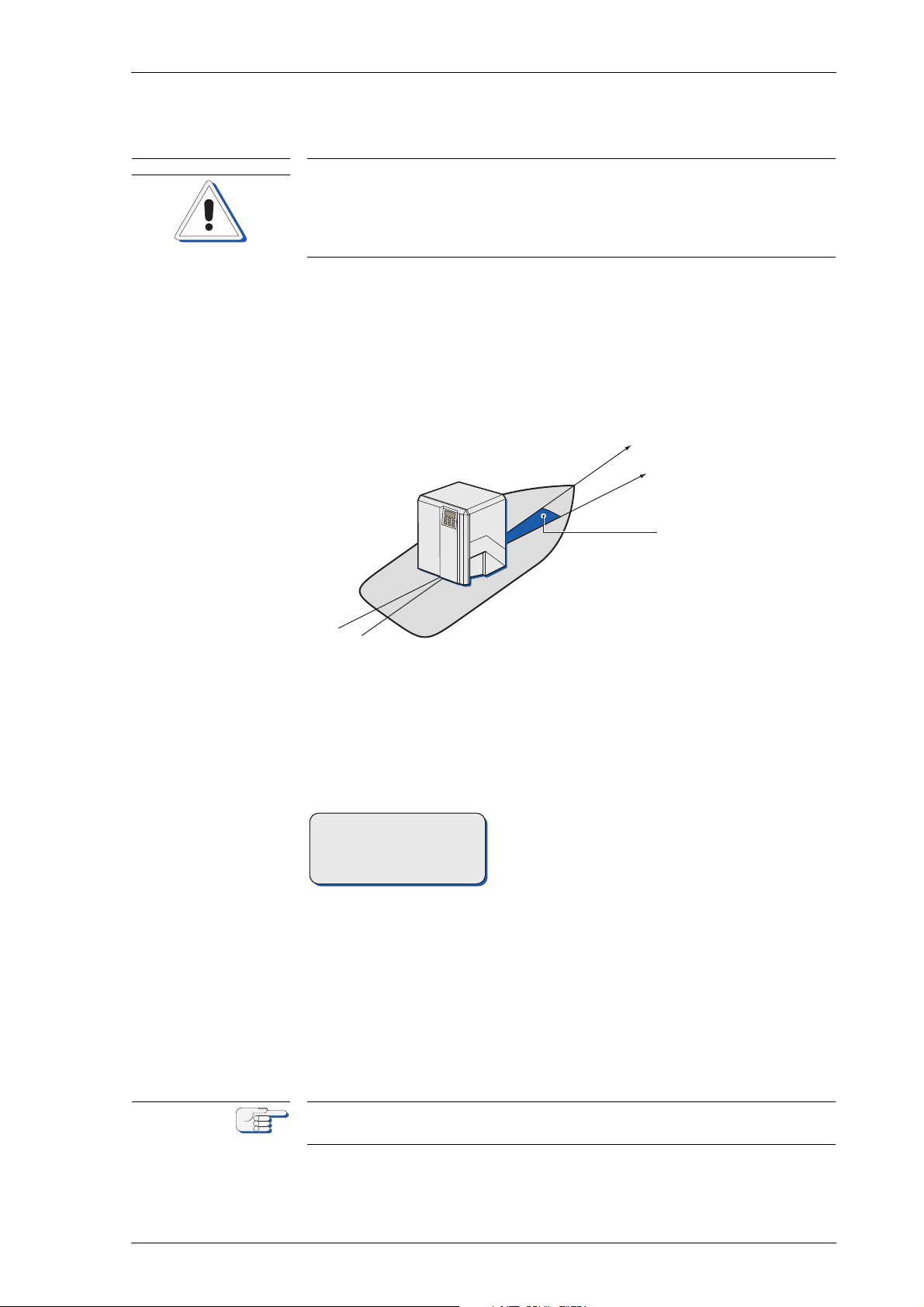
k^sfd^q u jh N MRSPQPLc
`^rqflk
compass orientation
vessel's fore-and-aft axis
alignment error
ALIGN ERROR COR R.
SERVICE SETUP
+000.0°
kçíÉ
TKS ^дбЦегЙен=bккзк=`зккЙЕнбзе
Risk of inaccurate alignment error correction
The compass must have been in continuous operation for at least 4 hours
before the alignment error can be determined accurately.
If bearing repeaters are used to determine the true heading, these must
be properly aligned to the vessel's fore-and-aft axis.
In order to obtain correct heading data, the existing alignment error (the
angular difference between the compass orientation and the vessel's
fore-and-aft axis) must be determined and the required correction
applied. Alignment error is 0° if the sides of the compass housing run
exactly parallel to the vessel‘s longitudinal axis and the back of the
housing points dead ahead. The alignment error correction is carried
out electronically by setting the correction value in the Service Setup 1.
qз=Е~кку=змн=нЬЙ=~дбЦегЙен=Йккзк=ЕзккЙЕнбзеW
1. Determine the existing alignment error by comparing the compass
heading with the vessel's true heading. The true heading must be
known to an accuracy of at least 0.5°.
2. Go to the Service Setup 1 and select the align error correction submenu, see “Configuration Menu - Service Setup 1” on page 8-1 for
details.
3. Enter the required correction
value.
⇒ The correction value equals the
alignment error with the sign
reversed.
bñ~ãéäÉW
The vessel’s true heading is
123.0°,
the compass displays 123.4°,
the alignment error is therefore
0.4°,
thus, the required correction
value is - 0.4°.
After accurate correction of the alignment error, the compass is to display the vessel's true heading with an accuracy of at least 0.5°.
^дбЦегЙен=bккзк=`зккЙЕнбзе TJV
Page 100
MRSPQPLc k^sfd^q u jh N
`^rqflk
kçíÉ
kçíÉ
`^rqflk
TKT j~ЦеЙнбЕ=`згй~лл=`~дбДк~нбзе
Risk of inaccurate magnetic compass calibration
The magnetic compass heading calibration corrects deviations due to the
combined effects of the magnetic environment, the particular sensor
being used and the receiving circuitry on the master PCB.
Therefore, a new calibration must always be carried out when:
- the steering magnetic compass is exchanged or newly adjusted,
- the magnetic compass heading sensor is exchanged and,
- when the master PCB is exchanged, in case a fluxgate sensor is used.
Never use a true heading source, e.g. a gyrocompass, as the calibration
reference.
Never attempt to correct residual deviations of a properly adjusted magnetic compass by means of the calibration table.
Ideally, the magnetic compass heading displayed at the
NAVIGAT X MK 1 would exactly match the indication of the steering
magnetic compass (at a given mag. variation of 0.0°).
In practice, however, deviations will occur between the steering magnetic compass heading and the heading data transmitted by a fluxgate
sensor of a magnetic compass or an electronic compass, as displayed at
the NAVIGAT X MK 1.
The NAVIGAT X MK 1 automatically corrects such deviations if a calibration table has been stored and calibration is activated in the User Setup.
The Magnetic Compass Calibration Table shall only be switched on for
automatic magnetic compass heading correction in case a magnetic
compass is indeed connected to the NAVIGAT X MK 1 system via a fluxgate sensor.
If magnetic compass heading is received from an already calibrated
source, such as a NAVITWIN, NAVIPILOT or a self-calibrating electronic
compass, magnetic compass calibration at the NAVIGAT X MK 1 is not
required and must be disabled.
`~дбДк~нбзе=mкзЕЙЗмкЙ=lоЙкобЙп
Risk of inaccurate magnetic compass calibration
The magnetic compass used as the calibration reference must be properly installed and adjusted.
The procedure should be carried out in calm seas only.
The magnetic compass calibration is a two-step procedure:
• At first, the existing deviations between the indication of the steering
magnetic compass and the magnetic compass heading displayed at
the NAVIGAT X MK 1 must be determined. This requires that the vessel is swung very slowly through a full circle so that for each 10° of
magnetic compass heading (0, 10, …, 350°) the corresponding display value is obtained.
• Secondly, the resultant correction values are calculated and entered
into the magnetic compass heading calibration table of the
TJNM j~ЦеЙнбЕ=`згй~лл=`~дбДк~нбзе
 Loading...