

Page 1
Spencer
®
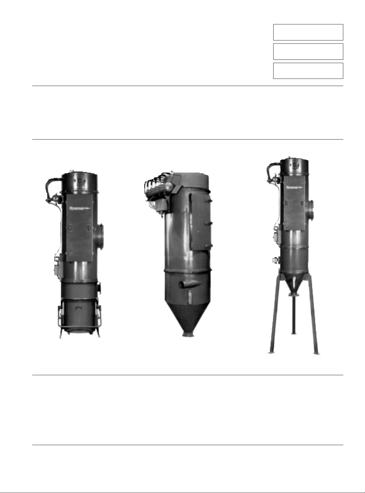
Jet-Clean™ Separator
Installation, Operation
and Maintenance Instructions
Important
Do not operate machine in unstable, low-flow range (surge).
Read and become familiar with this manual prior to uncrating and installing your Spencer Vacuum equipment. This precision
equipment is capable of extended service and lifespan. Realization of this potential can best be achieved through proper
handling and adherence to the instructions detailed here. Damage resulting from failure to follow correct procedures
will void warranty.
The Spencer Turbine Company Windsor, Connecticut 06095 Form KK5
Serial No:
Model No:
Filter Bags:
Page 2

Contents
Pages
I General Information 2
II Separator Operation 2
III Installation 3
IV Operation and Maintenance 5
V Trouble Shooting Guide — Separators 6
Warranty:
Spencer warrants that this product will be free from defects in
material and workmanship for a period of 18 months from date
of shipment or 12 months from date of start-up, whichever
comes first. Within the warranty period, we shall repair or
replace, F.O.B. our Factory or designated service center, such
products that are determined by us to be defective.
Caution: The Spencer Turbine Company is not responsible
for wear or corrosion caused by the material being handled
or failure due to corrosion or abrasion.
This warranty will not apply to any product which has been
subjected to misuse, negligence, or accident or misapplied
or improperly installed, or for failure due to corrosion or
abrasion. The warranty will not apply to any product which
has been disassembled, repaired or otherwise altered by
any persons not authorized by our Service Department.
The guarantee of the control manufacturer will govern the
extent of our guarantee on such equipment. Warranty work on
the controls must be authorized by Spencer and must be performed in an authorized shop as designated by the control
manufacturer.
See Form 706 for complete Terms and Conditions.
I. General Information
The Jet-Clean™ Separator is supplied with an electronic
sequencer in various NEMA enclosures, (NEMA 12 is standard).
This unit utilizes “shop air” to clean the filter bags.
This design is reliable under severe climate conditions and
capable of continuous operation. The unit is easy to install.
Only one connection to high pressure air is necessary to ready
the unit for operation.
Removable Dirt Can Design
Available on all Jet-Clean Separators. Depending on the size of
the separator, dirt cans will be supplied in 3 cu. ft. or 7
1
/2cu. ft.
capacities. Each dirt can is provided with ball bearing casters
and two lifting handles to facilitate removal from the separator
and dumping. The dirt can is held in place by a can arrangement and is removed by lifting the handle. When the can is
replaced and the handle lowered the can is locked in place.
Hopper Bottom Design
The Hopper Bottom design uses a 60° cone section that terminates in a flange. Generally, more storage capacity can be
realized than in the removable dirt can design. For continuous
dumping of material, the hopper bottom style can be utilized
along with one of several types of automatic dumping devices.
Plastic Dirt Can Liner and Equalizing Line
Separators with removable dirt cans can be equipped with an
equalizing line which allows use of a plastic dirt can liner. This
option is recommended when hazardous or extremely dusty
materials are being handled. The equalizing line uses system
vacuum to hold the plastic bag (liner) in place in the dirt can
while the system is in operation. When the system is shut down
and the dirt can is removed from the separator, the collected
material can be easily and cleanly disposed of by tying off the
top of the plastic bag and removing it from the dirt can. A new
bag is then placed in the dirt can and the can replaced and its
equalizing line reconnected to prepare the system for continued operation.
Bag Cleaning Control
The Jet-Clean Separator has an ASME code welded air tank
with pressure gage and pressure-relief valve. The bag cleaning
control is time-based and is designed to cycle each of the air
operated diaphragm valves at a preprogrammed rate. This
program is determined by the field conditions including type of
material collected and customer requirements regarding the
system.
Material Level Indicator (Optional)
The material level indicator senses high material level and can
be wired to: shut down the system, empty the separator,
sound an alarm, activate a light or start a rotary valve.
II. Separator Operation
The Spencer Jet-Clean Separator is designed to separate airborne material from the air stream of cleaning or conveying
system and to collect it for use or disposal. Large particles of
material are separated from the air stream by the cyclonic
action induced by the separator casing design. Fine particles
which still remain in the reduced velocity air are collected on
the outside surface of the bags. Eventually, this material begins
to build up on the bags to form what is known as “bag cake.”
As bag cake continues to build up on the bags, the resistance
to air flow through the bags increases. this is indicated by an
increase in differential pressure across the bags and is measured by the manometer supplied with each separator.
For any given material, there is an optimum amount of bag cake
which should be allowed to form since it actually enhances the
filtering efficiency of the bags. Less than the optimum amount
will result in less than ideal (although in most cases adequate)
filtration. Too much cake will cut down on the air flow and may
actually adversely affect conveying velocity in the system. In
general, an average pressure drop of 4” H
2
O across the filter
bags will provide good results although exceptions to this will be
found. A certain amount of trial-and-error work with any new
system will usually be necessary to determine the best pressure
drop across the bags for that system.
To prevent too much cake from accumulating, the Spencer JetClean Separator’s control initiates a backwash of clean, high
pressure air through the bags.
Special nozzles direct the high pressure air into the bags so as
to induce additional backflow of the air from the clean air
plenum through the bags. The blast of high pressure air in
combination with induced backflow causes the filter bags to
puff out, thus loosening the collected cake. Reverse airflow
through the bags helps blow this loosened dust away from the
bags so it can drop to the bottom of the separator where it is
collected.
2
Page 3
The Separator is designed so that only a few of the bags are
being pulsed at the same time. Under this arrangement, the
bags that are not being cleaned provide uninterrupted filtering
service.
Start Up
On start up, the manometer should read approximately
1
/2” H2O
differential pressure and gradually climb to approximately 4.0”
H
2
O before the first cleaning cycle is initiated. After the cleaning
cycle, the manometer reading should have dropped, indicating
that proper cleaning is occurring. If the differential pressure
across the bags continues to climb, the cleaning cycle should
be set to operate more frequently. If this does not improve performance, check the trouble shooting guide. If trouble persists,
consult factory.
III. Installation
Receipt, Handling, and Storage
Each Jet-Clean Separator and its components and accessories
are carefully crated and packaged to assure arrival at the site
of installation in safe condition. Any damage suffered in transit
should be reported to the carrier immediately. Product damage
should also be reported to The Spencer Turbine Company so
that we may anticipate any need for repairs.
Handling of the Spencer Jet-Clean Separator is simplified by
leaving the unit on its shipping skid until it is located in its
installation area. If the unit is to be slung or hoisted, the lifting
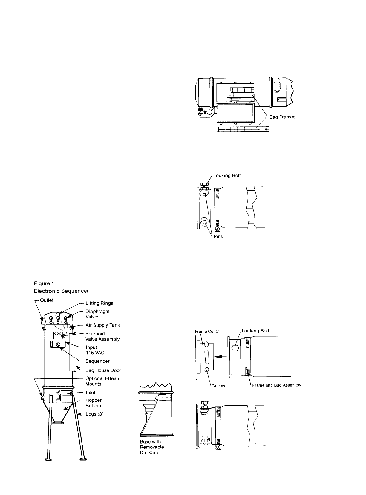
rings (see Figure 1) provided should be employed.
Whenever possible, delivery of the Jet-Clean Separator should
be scheduled to keep storage time at a minimum. When storage
is necessary, the unit should be kept in a cool, dry place and
should not have other items stored on top of it.
Step One: Install the filter bags and bag frames according to
the following procedure.
A. Before the separator is placed in an upright position, open
the bag house door and remove the bag frames and box of
filter bags which are shipped loose inside.
B. Pull a filter bag over the bag frame until the bag end is
immediately next to the locking bolt as shown below.
Position and tighten the bag clamp.
C. The bag frame assembly can now be installed in the Jet-
Clean Separator bag head. Place the bag frame assembly
into the separator and, beginning with the bag furthest from
the separator door, make contact with the frame collar. Turn
in a clockwise direction to engage the frame pins into the
holder guides. Note that when the bag frame assembly is
secure on the frame collar, the locking bolt must be visible
in order for it to be tightened. If, after installation of the bag
frame assembly, the locking bolt is not visible, remove the
frame, reposition and reinstall. When properly installed,
tighten the locking bolt.
3
Page 4
D. Continue to install the bag frame assemblies in the same
manner working from the back of the separator toward the
access door. Place the remaining three or four bag frame
assemblies into the separator before attaching each of them
to their respective collars.
E. When all of the bag frame assemblies are installed the sep-
arator is ready for installation or reuse.
Step Two: Using the lifting rings provided, stand the separator
in an upright position and locate the separator in its installation
area either on its legs or by using the I-beam mounting lugs, if
you have ordered your separator with this mounting option.
(see Figure 1)
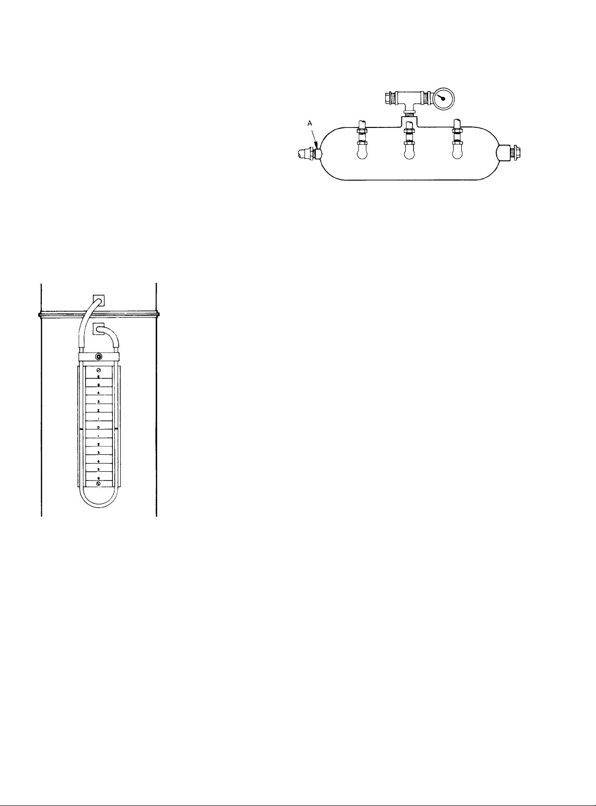
Step Three: A manometer, which indicates pressure drop
across the filter bags, is supplied with each Jet-Clean Separator
to assist in selecting the optimum bag cleaning frequency for
each individual installation. With most materials, bags should be
cleaned with a frequency that maintains a maximum pressure
drop across the bags for approximately 4” of water.
Two pressure taps, one on either side of the bag head, are
located near the top of the separator opposite the air supply
tank. After pouring the liquid (supplied with the manometer)
into the manometer tube, connect the two manometer tube
ends, one to each tap, and mount the manometer on the side of
the separator by means of its magnetic mount. (see Figure 2)
Install the manometer while the system is not in operation to
prevent the manometer liquid from being pulled into the
Separator.
Caution: When the unit is installed outdoors and temperatures below 32°F (0°C) are expected, be sure to use the
supplied liquid which will not freeze.
This manometer has been calibrated to use only the oil supplied
(0.826 sp. gr.). For replacement oil, contact the factory.
Step Four; Installation of Bag Pulse Sequencer:
Air Supply Connection
Remove the threaded plug from the 1” N.P.T. female pipe fitting
located at “A” which is the end of the air supply tank and connect
a supply of 100 psi to 125 psi air to the separator’s tank at this
point. All other connections have been made at the factory.
(see Figure 3)
Electronic Sequencer Connection (Standard)
A 120 VAC 60 cycle input must be wired to the control unit. The
hot line must be connected to the door mounted selector switch
and the neutral line must be connected to terminal 12 on the
printed circuit board.
Important: The 100 psi to 125 psi air supplied to the separator
must be oil-free, clean and dry (suitable for use with air-operated
valves and controls) and must be available at a rate of at least
15 cfm in order to properly operate the unit and provide clean,
dry air for bag cleaning.
No adjustments should be made to the internals of the
sequencer of the Jet-Clean Separator except for cycle time.
Each unit is completely tested prior to shipment and is preset
for proper operation at the factory. Any malfunction of the
control should be reported to your Spencer Representative or
to The Spencer Turbine Company Service Department in
Windsor, Connecticut.
IV. Operation
and Maintenance
Caution: The Spencer Turbine Company is not responsible
for wear or corrosion caused by the material being handled
or failure due to corrosion or abrasion.
Removal and installation of
twist-off Jet-Clean Separator Bag Frames
The Spencer twist-off bag frame assembly is unique because a
simple turn allows for easy removal or reinstallation. A locking
bolt prevents inadvertent loosening of the unit. To change the
filter bag, proceed as follows:
1. Locate and loosen the locking bolt.
2. Twist the bag frame in a counter-clockwise direction and
allow the male pins on the bag frame to ride down the
guides located on the frame collar.
3. Remove the bag frame assembly from the separator.
4. Loosen the bag clamp and remove the filter bag.
5. Install a new filter bag and re-tighten bag clamp.
6. Re-insert bag frame assembly into the separator. Note here
that when the bag frame is secure on the bag collar the
locking bolt must be visible in order to be tightened.
7. With this in mind, raise the bag frame assembly into contact
with the bag collar and turn in a clockwise direction to reengage the frame pins into the holder guides.
8. When the bag frame assembly is fully hand-tightened, tighten
the locking bolt.
4
Figure 2
Figure 3
Page 5
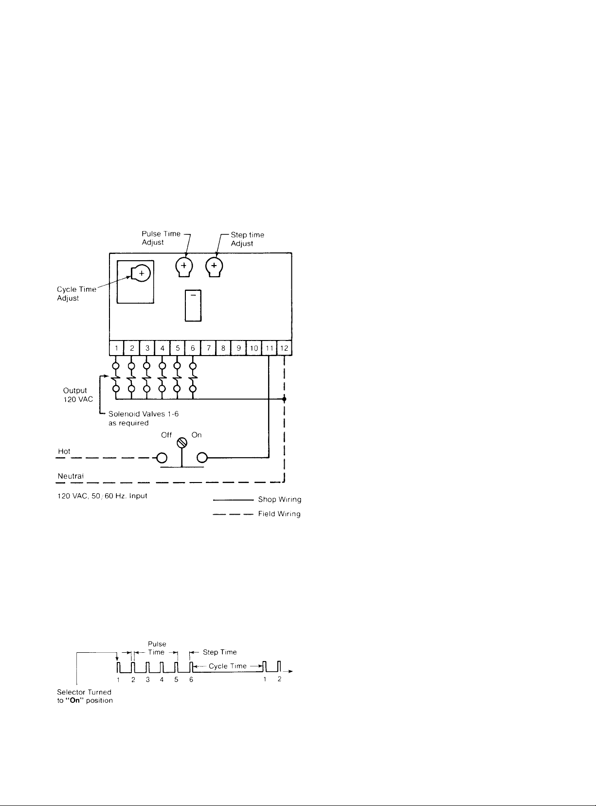
Description and adjustments for the Electronic Sequencer
The Electronic Sequencer furnished by Spencer contains the
following standard design features: Solid state controls, solenoid
pilot valves, 120 VAC 60 Hz input and NEMA 12 enclosure.
NEMA 4 and NEMA 7 & 9 enclosures are optional.
There are three adjustments that can be made on the Electronic
Sequencer. The first, Pulse Time, which is the actual length of
time that the air blast lasts, is adjustable from 0.1 second to
1.0 second. The second, Step Time, which is the length of time
between pulses, can be adjusted from 1.0 second to 1.0
minute. The third, Cycle Time, the time between cycles, can be
adjusted from 1.0 minute to 1.0 hour.
These adjustments are made by using a pocket size screwdriver
to turn the required potentiometer clockwise to increase; counterclockwise to decrease.
Cycle Time– 1 minute to 1 hour (preset at 10 min.)
Pulse Time– 30 milliseconds to 1.2 seconds (preset at 450 m.s.)
Step Time –1 second to 60 seconds (preset at 7.5 sec.)
1. Output starts at No. 1, then No. 2 and so on to the last selected
output, then back to No. 1 after Cycle Time is completed.
2. Turning selector switch on “OFF” then back to “ON” resets
the above.
5
Page 6

V. Trouble Shooting Guide-Separators
Trouble
High differential
pressure across bags
Note: although a
differential pressure of
1” to 6” H
2
O can be
considered normal,
most installations are
designed for a
differential of 4 inches.
Seepage –
Visible Discharge
Insufficient Suction
Unable to Maintain
Compressed Air
Pressure
Poor Filter Bag Life
No Air Released Thru
Injection Holes.
Probable Cause
Overloaded by too much air.
Improper compressed air supply.
System length shorter than design length.
Filter bag loading caused by too much vacuum
for system.
Sequencer will not pulse
Leaky air lock or dust discharge valve causing
filter overload.
Moisture-laden bags.
Excessive dust in the clean air plenum (from a
previously leaky bag) often impregnates the
bags in the reverse direction.
Static electricity.
Bags improperly installed.
Loose bag clamps.
Torn bags or holes in bags.
Vacuum producer.
High differential pressure.
Blockage in system.
Leaking duct work, access doors, discharge
valve or airlock.
Improper duct size or run size.
Poor system design.
Faulty or too small compressor or too small
service pipe.
Pipe leaks.
Material build-up in hopper.
Incorrect bag cage installation allowing friction
between outside elements and housing.
Abrasion caused by impingement of high velocity
particles.
Bag cleaning too frequent.
Defective diaphragm valve.
Defective Sequencer.
Faulty wiring or improper air line connection.
Corrective Action
System design or leaks in system.
100 to 125 psi is required. Air should be clean
and dry.
Reduce vacuum with blast gate located on vacuum
producer discharge.
Is air on? Check air line installation at separator.
Check for moisture in compressor air lines.
Check operation of air dryer. (moisture in line)
Repair or replace defective parts or entire unit.
Speed-up airlock rotation.
Run the cleaning mechanism without moving air
through the filter unit and eliminate moisture.
Check compressed air dryer.
Check filter bags clean or replace defective bags
and clean out plenum. Remove and dry clean
bags.
Grounded bags. (Special order only.)
Check bag installation and re-install, if neces-
sary.
Tighten clamps.
Repair or replace bags.
Check direction of vacuum producer rotation.
See above instructions for high differential pressure.
Remove blocking material.
Repair or replace seals.
Replace with original design specification.
Check against original design specifications.
Replace defective parts or use larger compressor
or install larger pipe line.
Repair and reseal connections.
Check build-up of material in hopper. Check airlock operation – it may leak.
Make sure filter bag cages are installed vertically
and not touching other bags or housing.
Reduce air flow-through filter. Separator too
small, need larger.
Slow down backwash cycle. NOTE: Contact
Service or Engineering Departments for Special
Problems.
Check and replace valve.
Consult Factory.
Check installation and start-up instructions.
6
Page 7

7
Filter Bag Part No.
Filter Bag Maintenance Record
Date Filter Bag Material
Date Changed
V acuum Accessories Record
(Hoses, Tools, V alves)
Part No.
Description
Page 8
Industrially rated products offering effective solutions
for air and gas moving problems:
• Modular central vacuum systems
• Mobile or stationary integrated vacuum units
• Dust collectors and separators
• Multi-stage centrifugal blowers
• Single stage centrifugal blowers
• Regenerative blowers and packages
• Positive displacement blowers and packages
• Gas boosters
• Custom-engineered products with special materials for extreme
temperatures and pressure
Complementary accessories with single source
convenience and compatibility:
• Standard and custom electrical control panels - UL, CUL and CE
Listed available
• Comprehensive selection of tubing, fittings, vacuum hoses, valves
and tools
• Valves, gauges, couplings, shrink sleeves, vibration isolators and
other system components
Comprehensive engineering and other customer
support services:
• The industry’s largest complement of technical specialists in air and
gas moving technology
• Worldwide parts and service organization
• Application research and testing facility
• Product selection process aided by internal computer program
Worldwide organization of sales representatives and
distributors offering:
• Product selection, installation and operation assistance
• Comprehensive system design services
• Follow-up services and troubleshooting
For the name and telephone number of your local
Spencer Representative, call 1-800-232-4321.
Products & Services
®
The Turbine Company, 600 Day Hill Road, Windsor, CT 06095-4706
Since 1892 moving air and gas for a cleaner environment
TEL 800-232-4321◆860-688-8361◆FAX 860-688-0098◆www.spencerturbine.com
Form KK5, Copyright © 2001 The Spencer Turbine Company 1201CF.5
 Loading...