


Owner’s Manual
Notice d’utilisation
Manual del Propietario
For professional use only
Do not use this equipment before reading this manual!
PowrTwin 8900GH
Model Number: |
|
Gas Bare |
449-920 |
Gas Complete |
449-911 |
DC Electric Bare |
449-912 |
Gas/Electric Complete |
449-991 |
Printed in the U. S. A.
NOTE: This manual contains important warnings and instructions. Please read and retain for reference.
0503 © 2003 Titan Tool Inc. All rights reserved. Form No. 313-1816, REV C
Español Français English

Table of Contents |
|
|
|
|
|
|
|
|
|
|||||
|
|
|
|
|
|
WARNING |
|
|
||||||
Safety Precautions . . . . . . . . . . . . . . . . . . . . . . . . . . . |
. . . . |
2 |
|
|
|
|
||||||||
|
. . . . . . . . . . . . . . . . . . . . . . . . .Grounding Instructions |
. . . |
3 |
|
HAZARD: Injection injury - A high pressure stream |
|||||||||
|
Gasoline Engine Safety |
|
4 |
|
||||||||||
|
. . . |
|
|
produced by this equipment can pierce the |
||||||||||
|
Français |
|
28 |
|
|
|||||||||
|
. . |
|
|
skin and underlying tissues, leading to serious |
||||||||||
|
Español |
|
54 |
|
|
|||||||||
|
. . |
|
|
injury and possible amputation. See a |
||||||||||
Specifications |
|
4 |
|
|
||||||||||
. . . |
|
|
physician immediately. |
|||||||||||
Introduction |
|
5 |
|
|
||||||||||
. . . |
|
DO NOT TREAT AN INJECTION INJURY AS A SIMPLE |
||||||||||||
Operation . . . . . . . . . . . . . . . . . . . . . . . . . . . . . . . . . . . |
. . . |
5 |
|
|||||||||||
|
Fueling . . . . . . . . . . . . . . . . . . . . . . . . . . . . . . . . . . . . |
. . . |
5 |
|
CUT! Injection can lead to amputation. See a physician |
|||||||||
|
Setup . . . . . . . . . . . . . . . . . . . . . . . . . . . . . . . . . . . . . |
. . . |
6 |
|
immediately. |
|||||||||
|
Preparing to Paint . . . . . . . . . . . . . . . . . . . . . . . . . . . . |
. . . |
7 |
|
The maximum operating range of the gun is 3300 PSI / 23 |
|||||||||
|
Painting. . . . . . . . . . . . . . . . . . . . . . . . . . . . . . . . . . . . |
. . . |
8 |
|
MPa fluid pressure. |
|||||||||
|
Pressure Relief Procedure. . . . . . . . . . . . . . . . . . . . . . |
. . . |
9 |
|
PREVENTION: |
|||||||||
Cleanup |
|
9 |
|
|||||||||||
. . . |
|
|
• NEVER aim the gun at any part of the body. |
|||||||||||
|
Cleaning a Clogged Tip . . . . . . . . . . . . . . . . . . . . . . . . |
. . |
10 |
|
|
|||||||||
Maintenance . . . . . . . . . . . . . . . . . . . . . . . . . . . . . . . . . |
. . |
10 |
|
|
• NEVER allow any part of the body to touch the fluid |
|||||||||
|
Daily Maintenance . . . . . . . . . . . . . . . . . . . . . . . . . . . . |
. . |
10 |
|
|
stream. DO NOT allow body to touch a leak in the fluid |
||||||||
|
Maintaining the Filter Assembly . . . . . . . . . . . . . . . . . . |
. . |
10 |
|
|
hose. |
||||||||
|
Maintaining the Hydraulic System . . . . . . . . . . . . . . . . |
. . |
11 |
|
|
• NEVER put your hand in front of the gun. Gloves will not |
||||||||
|
Maintaining the Fluid Section |
|
11 |
|
|
|||||||||
|
. . |
|
|
provide protection against an injection injury. |
||||||||||
|
. . . . . . . . . . . .Basic Engine Maintenance (gas engine) |
. . |
11 |
|
|
• ALWAYS lock the gun trigger, shut the pump off, and release |
||||||||
|
Replacing the Motor Brushes (electric motor) |
|
12 |
|
|
|||||||||
|
. . |
|
|
all pressure before servicing, cleaning the tip or guard, |
||||||||||
. . . . . . . . . . . . . . . . . . . . . . . . . . . . . .Troubleshooting |
. . |
13 |
|
|
changing tip, or leaving unattended. Pressure will not be |
|||||||||
|
. . . . . . . . . . . . . . . . . . . . . . . . . . . . . . . . .Airless Gun |
. . |
13 |
|
|
released by turning off the motor. The PRIME/SPRAY knob |
||||||||
|
. . . . . . . . . . . . . . . . . . . . . . . . . . . . . . . .Fluid Section |
. . |
13 |
|
|
must be turned to PRIME to relieve the pressure. Refer to |
||||||||
|
. . . . . . . . . . . . . . . . . . . . . . . . . . . . . .Hydraulic Motor |
. . |
14 |
|
|
the PRESSURE RELIEF PRESSURE described in the pump |
||||||||
|
. . . . . . . . . . . . . . . . . . . . . . . . . . . . . .Spray Patterns |
. . |
15 |
|
|
manual. |
||||||||
Parts Lists and Service Instructions |
16–27 |
|
|
|||||||||||
|
|
• ALWAYS keep the tip guard in place while spraying. The |
||||||||||||
|
Main Assembly . . . . . . . . . . . . . . . . . . . . . . . . . . . . . . |
. . |
16 |
|
|
|||||||||
|
Bleed Hose Assembly with Valve . . . . . . . . . . . . . . . . . |
. . |
16 |
|
|
tip guard provides some protection but is mainly a |
||||||||
|
Cart Assembly . . . . . . . . . . . . . . . . . . . . . . . . . . . . . . . |
. . |
17 |
|
|
warning device. |
||||||||
|
Belt Guard Assembly . . . . . . . . . . . . . . . . . . . . . . . . . . |
. . |
17 |
|
|
• ALWAYS remove the spray tip before flushing or cleaning |
||||||||
|
Hydraulic System . . . . . . . . . . . . . . . . . . . . . . . . . . . . |
. . |
18 |
|
|
the system. |
||||||||
|
DC— Electric Convertokit . . . . . . . . . . . . . . . . . . . . . . |
. . |
19 |
|
|
• The paint hose can develop leaks from wear, kinking and |
||||||||
|
Gas Convertokit. . . . . . . . . . . . . . . . . . . . . . . . . . . . . . |
. . |
20 |
|
|
abuse. A leak can inject material into the skin. Inspect |
||||||||
|
Filter Assembly . . . . . . . . . . . . . . . . . . . . . . . . . . . . . . |
. . |
20 |
|
|
the hose before each use. |
||||||||
|
Bleed Valve Assembly . . . . . . . . . . . . . . . . . . . . . . . . . |
. . |
21 |
|
|
• NEVER use a spray gun without a trigger lock and trigger |
||||||||
|
Siphon Hose Assembly |
|
21 |
|
|
|||||||||
|
. . |
|
|
guard in place and in good working order. |
||||||||||
|
Hydraulic Motor |
|
22 |
|
|
|||||||||
|
. . |
|
|
• All accessories must be rated at or above 3300 PSI / 23 |
||||||||||
|
Fluid Section . . . . . . . . . . . . . . . . . . . . . . . . . . . . . . . . |
. . |
24 |
|
|
|||||||||
|
Gun Manifold Assemblies (optional) . . . . . . . . . . . . . . . |
. . |
26 |
|
|
MPa. This includes spray tips, guns, extensions, and |
||||||||
|
SAE O-Ring Fitting Installation. . . . . . . . . . . . . . . . . . . |
. . |
27 |
|
|
hose. |
||||||||
. . . . . . . . . . . . . . . . . . . .Accessories and Service Kits |
. . |
27 |
|
|
NOTE TO PHYSICIAN: |
|
||||||||
|
Airless Tip Selection . . . . . . . . . . . . . . . . . . . . . . . . . . |
. . |
27 |
|
|
Injection into the skin is a traumatic injury. It is |
|
|||||||
Limited Warranty |
|
80 |
|
|
|
|||||||||
. . |
|
|
important to treat the injury as soon as possible. DO |
|
||||||||||
Safety Precautions |
|
|
|
|
|
|
||||||||
|
|
|
|
|
NOT delay treatment to research toxicity. Toxicity is a |
|
||||||||
This manual contains information that must be read and |
|
|
|
|
|
concern with some coatings injected directly into the |
|
|||||||
|
|
|
|
|
blood stream. Consultation with a plastic surgeon or |
|
||||||||
understood before using the equipment. When you come to |
|
|
|
|
reconstructive hand surgeon may be advisable. |
|
||||||||
an area that has one of the following symbols, pay particular |
|
|
|
|
|
|
|
|
||||||
attention and make certain to heed the safeguard. |
|
|
|
|
HAZARD: EXPLOSION OR FIRE - Solvent and paint fumes |
|||||||||
|
|
|
|
|
|
|
|
|
|
|
can explode or ignite. Severe injury and/or |
|||
|
|
|
WARNING |
|
|
|
|
|
||||||
|
|
|
|
|
|
|
|
|
property damage can occur. |
|||||
|
|
|
|
|
|
|
|
|
|
|
||||
|
|
|
|
|
|
|
|
|
|
PREVENTION: |
||||
This symbol indicates a potential hazard that may cause |
|
|||||||||||||
|
|
• Provide extensive exhaust and fresh air introduction to |
||||||||||||
serious injury or loss of life. Important safety information |
|
|
keep the air within the spray area free from accumulation |
|||||||||||
will follow. |
|
|
|
|
|
of flammable vapors. |
||||||||
|
|
|
CAUTION |
|
|
|
|
|
|
• Avoid all ignition sources such as static electric sparks, |
||||
|
|
|
|
|
|
|
|
|
open flames, pilot lights, and hot objects. Connecting or |
|||||
This symbol indicates a potential hazard to you or to the |
|
|
disconnecting power cords or working light switches can |
|||||||||||
|
|
make sparks. |
||||||||||||
equipment. Important information that tells how to |
|
|
|
|
|
|||||||||
|
|
|
|
|
• Do not smoke in spray area. |
|||||||||
prevent damage to the equipment or how to avoid causes |
|
|
||||||||||||
of minor injuries will follow. |
|
|
|
|
|
• Fire extinguisher must be present and in good working |
||||||||
|
|
|
|
|
|
|
|
|
|
|
order. |
|||
|
NOTE: Notes give important information that should |
|
|
|
||||||||||
|
|
|
|
|
• Place paint pump in a well ventilated area. Flammable |
|||||||||
|
be given special attention. |
|
|
|
|
|
vapors are often heavier than air. Floor area must be |
|||||||
|
|
|
|
|
|
|
|
|
|
|
extremely well ventilated. The paint pump contains arcing |
|||
|
|
|
|
|
|
|
|
|
|
|
parts that emit spark and can ignite vapors. |
|||
|
|
|
|
|
|
|
|
|
|
|
• The equipment and objects in and around the spray area |
|||
|
|
|
|
|
|
|
|
|
|
|
must be properly grounded to prevent static sparks. |
|||
|
|
|
|
|
|
|
|
|
|
|
• Use only conductive or grounded high pressure fluid hose. |
|||
|
|
|
|
|
|
|
|
|
|
|
Gun must be grounded through hose connections. |
|||
|
|
|
|
|
|
|
|
|
|
|
• Power cord must be connected to a grounded circuit |
|||
|
|
|
|
|
|
|
|
|
|
|
(electric models only). |
|||
|
|
|
English |
|
|
2 |
|
|
© Titan Tool Inc. All rights reserved. |
|||||
|
|
|
|
|
|
|
|
|
|
|
|
|
|
|

•Always flush unit into a separate metal container, at low pump pressure, with spray tip removed. Hold gun firmly against side of container to ground container and prevent static sparks.
•Follow the material and solvent manufacturer's warnings and instructions.
•Use extreme caution when using materials with a flashpoint below 70° F (21° C). Flashpoint is the temperature that a fluid can produce enough vapors to ignite.
•Plastic can cause static sparks. Never hang plastic to enclose a spray area. Do not use plastic drop cloths when spraying flammable materials.
•Use lowest possible pressure to flush equipment.
GAS ENGINE (WHERE APPLICABLE)
Always place pump outside of structure in fresh air. Keep all solvents away from the engine exhaust. Never fill fuel tank with a running or hot engine. Hot surface can ignite spilled fuel. Always attach ground wire from pump unit to a grounded object, such as a metal water pipe. Refer to engine owner’s manual for complete safety information.
HAZARD: EXPLOSION HAZARD DUE TO INCOMPATIBLE MATERIALS - Will cause severe injury or property damage.
PREVENTION:
•Do not use materials containing bleach or chlorine.
•Do not use halogenated hydrocarbon solvents such as mildewcide, methylene chloride and 1,1,1 - trichloroethane. They are not compatible with aluminum.
•Contact your coating supplier about the compatibility of material with aluminum.
HAZARD: HAZARDOUS VAPORS - Paints, solvents, insecticides, and other materials can be harmful if inhaled or come in contact with the body. Vapors can cause severe nausea, fainting, or poisoning.
PREVENTION:
•Use a respirator or mask if vapors can be inhaled. Read all instructions supplied with the mask to be sure it will provide the necessary protection.
•Wear protective eyewear.
•Wear protective clothing as required by coating manufacturer.
HAZARD: GENERAL - This product can cause severe injury or property damage.
PREVENTION:
•Read all instructions and safety precautions before operating equipment.
•Always disconnect the motor from the power supply before working on the equipment (electric models only).
•Follow all appropriate local, state, and national codes governing ventilation, fire prevention, and operation.
•The United States Government Safety Standards have been adopted under the Occupational Safety and Health Act (OSHA). These standards, particularly part 1910 of the General Standards and part 1926 of the Construction Standards should be consulted.
•Use only manufacturer authorized parts. User assumes all risks and liabilities when using parts that do not meet the minimum specifications and safety devices of the pump manufacturer.
•Before each use, check all hoses for cuts, leaks, abrasion or bulging of cover. Check for damage or movement of couplings. Immediately replace the hose if any of these conditions exist. Never repair a paint hose. Replace it with another grounded high-pressure hose.
•All hoses, swivels, guns, and accessories must be rated at or above 3300PSI/23 MPa.
•Do not spray outdoors on windy days.
•Wear clothing to keep paint off skin and hair.
Grounding Instructions
Electric models must be grounded. In the event of an electrical short circuit, grounding reduces the risk of electric shock by providing an escape wire for the electric current. This product is equipped with a cord having a grounding wire with an appropriate grounding plug. The plug must be plugged into an outlet that is properly installed and grounded in accordance with all local codes and ordinances.
DANGER — Improper installation of the grounding plug can result in a risk of electric shock. If repair or replacement of the cord or plug is necessary, do not connect the green grounding wire to either flat blade terminal. The wire with insulation having a green outer surface with or without yellow stripes is the grounding wire and must be connected to the grounding pin.
Check with a qualified electrician or serviceman if the grounding instructions are not completely understood, or if you are in doubt as to whether the product is properly grounded. Do not modify the plug provided. If the plug will not fit the outlet, have the proper outlet installed by a qualified electrician.
This product is rated more than 15 amperes and is for use on a circuit having a nominal rating of 120 volts, or the product is for use on a circuit having a nominal rating more than 120 volts, and is factory-equipped with a specific electric cord and plug to permit connection to a proper electric circuit. Make sure that the product is connected to an outlet having the same configuration as the plug. No adapter should be used with this product. If the product must be reconnected for use on a different type of electric circuit, the reconnection should be made by qualified service personnel.
 CAUTION
Use only a 3-wire extension cord that has a 3-blade grounding plug and a 3-slot receptacle that will accept the plug on the product. Make sure your extension cord is in good condition. When using an extension cord, be sure to use one heavy enough to carry the current your product will draw. An undersized cord will cause a drop in line voltage resulting in loss of power and overheating. For lengths less than 50 feet, No. 12 AWG extension cords should be used. If an extension cord is to be used outdoors, it must be marked with the suffix W-A after the cord type designation. For example, a designation of SJTW-A would indicate that the cord would be appropriate for outdoor use.
© Titan Tool Inc. All rights reserved. |
3 |
English |
|
|
|

Gasoline Engine Safety
 WARNING
The engine exhaust from this unit contains chemicals known to the State of California to cause cancer, birth defects, or other reproductive harm.
1.Honda engines are designed to give safe and dependable service if operated according to instructions. Read and understand the Honda Owner's Manual before operating the engine. Failure to do so could result in personal injury or equipment damage.
2.To prevent fire hazards and to provide adequate ventilation, keep the engine at least 1 meter (3 feet) away from buildings and other equipment during operation. Do not place flammable objects close to the engine.
3.Children and pets must be kept away from the area of operation due to a possibility of burns from hot engine components or injury from any equipment the engine may be used to operate.
4.Know how to stop the engine quickly, and understand the operation of all controls. Never permit anyone to operate the engine without proper instructions.
5.Gasoline is extremely flammable and is explosive under certain conditions.
6.Refuel in a well-ventilated area with the engine stopped. Do not smoke or allow flames or sparks in the refueling area or where gasoline is stored.
7.Do not overfill the fuel tank. After refueling, make sure the tank cap is closed properly and securely.
8.Be careful not to spill fuel when refueling. Fuel vapor or spilled fuel may ignite. If any fuel is spilled, make sure the area is dry before starting the engine.
9.Never run the engine in an enclosed or confined area. Exhaust contains poisonous carbon monoxide gas; exposure may cause loss of consciousness and may lead to death.
10.The muffler becomes very hot during operation and remains hot for a while after stopping the engine. Be careful not to touch the muffler while it is hot. To avoid severe burns or fire hazards, let the engine cool before transporting it or storing it indoors.
11.Never ship/transport unit with gasoline in the tank.
 WARNING
DO NOT use this equipment to spray water or acid.
 CAUTION
Do not lift by cart handle when loading or unloading.
Warning Labels
Your sprayer has the English language warning labels. If you require these labels in French, German, or Spanish, or require additional English labels, order directly from Speeflo free of charge.
Part # |
Language |
313-771 |
English |
313-784 |
|
313-1837 |
|
313-1306 |
Spanish |
313-1307 |
|
313-785 |
French |
313-786 |
|
313-787 |
German |
313-788 |
|
|
|
Specifications
Gas Unit
Gallons per minute (GPM) ............... |
2.25 (8.5 LPM) |
Cycle rate per gallon........................ |
40 (10.5 cycles/liter) |
Maximum tip sizes ........................... |
1 gun = .050” |
|
2 guns = .035” |
|
3 guns = .029” |
|
4 guns = .025” |
|
5 guns = .021” |
Maximum pressure .......................... |
3300 psi (23 MPa) |
Power............................................... |
Honda 6.5 HP, 4-stroke, |
|
single cylinder, overhead |
|
valve engine w/oil alert |
Fuel capacity.................................... |
1.6 US gallons |
|
(approx. 2.5 hours run time) |
Halogenated solvent compatible...... |
Yes |
Weight .............................................. |
155 lbs. (70.3 kg.) |
Inlet paint filter ................................. |
10 mesh “Rock Catcher” |
Outlet paint filter............................... |
50 mesh, 18 in.2 |
Pump inlet ........................................ |
1” NPT(F) |
Pump outlet...................................... |
1/2” NPT(F) to paint filter |
Paint filter hose connections............ |
1/4” NPS(M) |
|
3/8” NPT(F) (plugged) |
Dimensions ...................................... |
42 1/2" L (108 cm) x |
|
27" W (68.6 cm) x |
|
34" H (86.6 cm) |
Fluid section wetted parts: |
|
Electroless nickel plated ductile iron, electroless nickel plated carbon steel, proprietary Severe Service 500™ hard chrome anti-wear surface, stainless steel, tungsten carbide, 37)(, thiokol impregnated leather, ultra high molecular weight polyethylene.
Electric Unit
Gallons per minute (GPM) ............... |
1.25 (4.7 LPM) |
Cycle rate per gallon........................ |
40 (10.5 cycles/liter) |
Maximum tip sizes ........................... |
1 gun = .036” |
|
2 guns = .026” |
|
3 guns = .019” |
Maximum pressure .......................... |
3300 psi (23 MPa) |
Power............................................... |
2 HP DC Motor, |
|
115V 15.5A, |
|
overload protected |
Halogenated solvent compatible...... |
Yes |
Weight .............................................. |
164 lbs. (74.4 kg.) |
Inlet paint filter ................................. |
10 mesh “Rock Catcher” |
Outlet paint filter............................... |
50 mesh, 18 in.2 |
Pump inlet ........................................ |
1” NPT(F) |
Pump outlet...................................... |
1/2” NPT(F) to paint filter |
Paint filter hose connections............ |
1/4” NPS(M) |
|
3/8” NPT(F) (plugged) |
Dimensions ...................................... |
42 1/2" L (108 cm) x |
|
27" W (68.6 cm) x |
|
34" H (86.6 cm) |
Fluid section wetted parts: |
|
Electroless nickel plated ductile iron, electroless nickel plated carbon steel, proprietary Severe Service 500™ hard chrome anti-wear surface, stainless steel, tungsten carbide, 37)(, thiokol impregnated leather, ultra high molecular weight polyethylene.
English |
4 |
© Titan Tool Inc. All rights reserved. |
|
|
|
Introduction
Congratulations on having selected the finest airless sprayer available in the world. Speeflo piston pumps are tireless workhorses — so tough they are virtually indestructible, even under the most severe service. Speeflo designs and builds equipment with superior quality and reliability. Equipment that will last for years with minimal maintenance and downtime. This equipment will make you money year after year. We thank you for your purchase and welcome you to our large and growing family of Speeflo users.
The unique ability of this PowrTwin to operate with either gas or electric power provides you with the flexibility to work indoors or outside where no electricity is available.
Hydraulic drive makes possible the longest stroke and slowest cycling pumps in the industry, which translates into low maintenance and longer life. Electric units operate quietly with no motor starting and stopping.
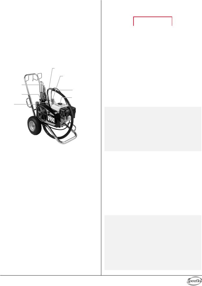
Pressure Control
Knob
Motor/Pump
Assembly
Hydraulic
Fluid Cap/
Dipstick
Bleed Hose
Bleed Valve
Gas Tank
Filter |
|
Siphon Hose |
|
||
|
|
Outlet
Fitting
This PowrTwin is equipped with Speeflo's Severe Service 500™ fluid pump. This technology will give you significantly longer rod, cylinder, and packing life than any other sprayer built in the world. This double ball piston pump employs a dependable and durable time-tested design. All pumps use a thick hard chrome plating on rod and cylinder parts. This plating process is harder than nitralloy, stainless steel, or hard chrome used by any other paint pump manufacturer and much more abrasion resistant. Highly polished parts reduce friction, extend packing life, and avoid damage from corrosion and abrasion. More than 100,000 of these pumps are in operation around the world.
This PowrTwin offers other cost saving features:
•Freeze-proof pressure control
•Choice of power — gas, electric, or both
•Tungsten carbide valve seats
•Self-adjusting packings
•Exclusive hand-tight swivel foot valve
•Large capacity inline paint filter
•Waterborne compatible
•"Floating Ball" pressure bleed valve
•5 gallon siphon hose and bleed line assemblies are standard
You have made an excellent choice. We know you will be pleased with your new PowrTwin. Thanks again for selecting Speeflo. We appreciate your business.
Operation
Fueling (gas engine)
 WARNING
Gasoline is extremely flammable and is explosive under certain conditions.
•ALWAYS turn the engine off before refueling.
•Refuel in a well-ventilated area.
•Do not smoke or allow flames or sparks in the refueling area or where gasoline is stored.
•Do not overfill the fuel tank. After refueling, make sure the tank cap is closed properly and securely.
•Be careful not to spill fuel when refueling. Spilled fuel or fuel vapor may ignite. If any fuel is spilled, make sure the area is dry before starting the engine.
•Avoid repeated or prolonged contact with skin or breathing of vapor.
•Keep out of the reach of children.
Fuel Specifications
•Use automotive gasoline that has a pump octane number of 86 or higher, or that has a research octane number of 91 or higher. Use of a lower octane gasoline can cause persistent "pinging" or heavy "spark knock" (a metallic rapping noise) which, if severe, can lead to engine damage.
NOTE: If "spark knock" or "pinging" occurs at a steady engine speed under normal load, change brands of gasoline. If spark knock or pinging persists, consult an authorized dealer of the engine manufacturer. Failure to do so is considered misuse, and damage caused by misuse is not covered by the engine manufacturer’s limited warranty.
Occasionally you may experience light spark knock while operating under heavy loads. This is no cause for concern, it simply means your engine is operating efficiently.
•Unleaded fuel produces fewer engine and spark plug deposits and extends the life of the exhaust system components.
•Never use stale or contaminated gasoline or an oil/gasoline mixture. Avoid getting dirt, dust, or water in the fuel tank.
Gasolines Containing Alcohol
If you decide to use a gasoline containing alcohol (gasohol), be sure its octane rating is at least as high as that recommended by the engine manufacturer. There are two types of "gasohol": one containing ethanol, and the other containing methanol. Do not use gasohol that contains more than 10% ethanol. Do not use gasoline containing methanol (methyl or wood alcohol) that does not also contain cosolvents and corrosion inhibitors for methanol. Never use gasoline containing more than 5% methanol, even if it has cosolvents and corrosion inhibitors.
NOTE: Fuel system damage or engine performance problems resulting from the use of fuels that contain alcohol is not covered under the warranty. The engine manufacturer cannot endorse the use of fuels containing methanol since evidence of their suitability is incomplete at this time.
Before buying gasoline from an unfamiliar station, try to find out if the gasoline contains alcohol. If it does, confirm the type and percentage of alcohol used. If you notice any undesirable operating characteristics while using a gasoline that contains alcohol, or one that you think contains alcohol, switch to a gasoline that you know does not contain alcohol.
© Titan Tool Inc. All rights reserved. |
5 |
English |
|
|
|
Setup
 WARNING
Read, understand, and follow all warnings before starting or operating this sprayer.
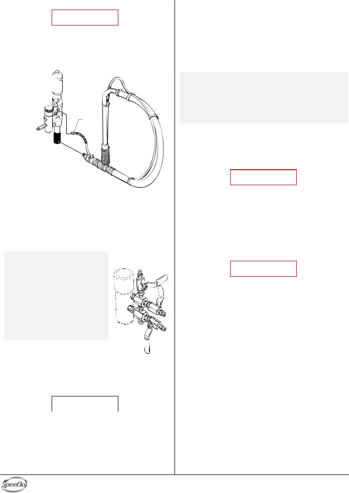
1.Connect the siphon hose to the fluid section and the bleed
hose to the bleed valve. They each have factory installed PTFE tape on the male end of the hoses and should be tightened wrench tight.
Bleed Valve 
Bleed
Hose
Fluid Section 
Siphon Hose
2.Attach a minimum of 50’ of nylon airless spray hose to the unit. Do not use PTFE tape or thread sealant on the spray hose connection.
3.Attach an airless spray gun to the spray hose. Do not attach the tip to the spray gun yet. Remove the tip if it is already attached.
a.To use two guns, remove the plug from the second gun outlet on the filter assembly. Connect a hose and gun to the outlet.
NOTE: The gas unit is engineered to handle up to 5 guns with .021" tips and the electric unit is engineered to handle up to 3 guns with .019” tips. For multiple gun operation, connect a multiple gun manifold to the single gun outlet. Connect a hose and gun to each outlet. Make sure the second gun outlet remains plugged.
4.Fill the oil cup 1/2 full with Speeflo Piston Lube (P/N 700-925) supplied by the factory. This extends packing life.
Multiple Gun
Manifold
5.Check the hydraulic fluid level daily before starting the unit. The hydraulic fluid level should be at the “Full” mark on the dipstick. Refer to the Maintenance section of this manual for hydraulic system maintenance instructions.
 CAUTION
Use of Speeflo's Coolflo™ Hydraulic Fluid is mandatory in the hydraulic system. Do not use any other hydraulic fluid. Use of any other hydraulic fluid may seriously damage the hydraulic system and will void the warranty.
6.For gas models, check the engine oil level daily before starting the unit. The gasoline engine oil level is determined by the engine manufacturer. Refer to the engine manufacturer’s service manual supplied with this unit.
7.For electric models, use a 20 amp service outlet. Always locate the electric model within 10 to 15 feet of the service outlet. Use a short electric cable and a long paint hose.
Any extension cord will create some voltage drop. If an extension cord is necessary, use only a grounded 3-wire #12 extension cord.
NOTE: If the unit is being operated in an area that is overloaded by other appliances or low voltage conditions, it is important to start the unit "unloaded." Tip the electric motor forward so that the belt is loosened and the motor starts without full load. This reduces the amperage draw on starting and may avoid tripping the circuit breaker.
8.Make sure the unit is grounded. All units are equipped with a grounding lug. A grounding cable (not supplied) should be used to connect the unit to a true earth ground. Check your local electrical regulations for detailed grounding instructions. See the Accessories and Service Kits section near the back of this manual for grounding cable ordering information.
 WARNING
Proper grounding is important. This applies to both gas and electric powered models. The passage of some materials through the nylon fluid hose will build up a static electric charge, which if discharged, could ignite solvent vapors present and create an explosion.
9.Strain all paints with a nylon strainer to ensure trouble free operation and freedom from frequent cleaning of the inlet screen and gun filter.
10Make sure the spray area is well ventilated to prevent hazardous operation with volatile solvents or exhaust fumes.
 WARNING
If lacquer or other flammable materials are to be sprayed, ALWAYS locate the unit outside the immediate spraying area. Failure to do so may cause an explosion.
11.Locate the unit outside the immediate spraying area to avoid clogged air intake of the engine or electric motor with overspray.
English |
6 |
© Titan Tool Inc. All rights reserved. |
|
|
|

Preparing a New Sprayer
If this unit is new, it is shipped with test fluid in the fluid section to prevent corrosion during shipment and storage. This fluid must be thoroughly cleaned out of the system with mineral spirits before you begin spraying.
 CAUTION
Always keep the trigger lock on the spray gun in the locked position while preparing the system.
1.Place the siphon hose into a container of mineral spirits.
2.Place the bleed hose into a metal waste container.
3.Set the pressure to minimum by turning the pressure control knob fully counterclockwise.
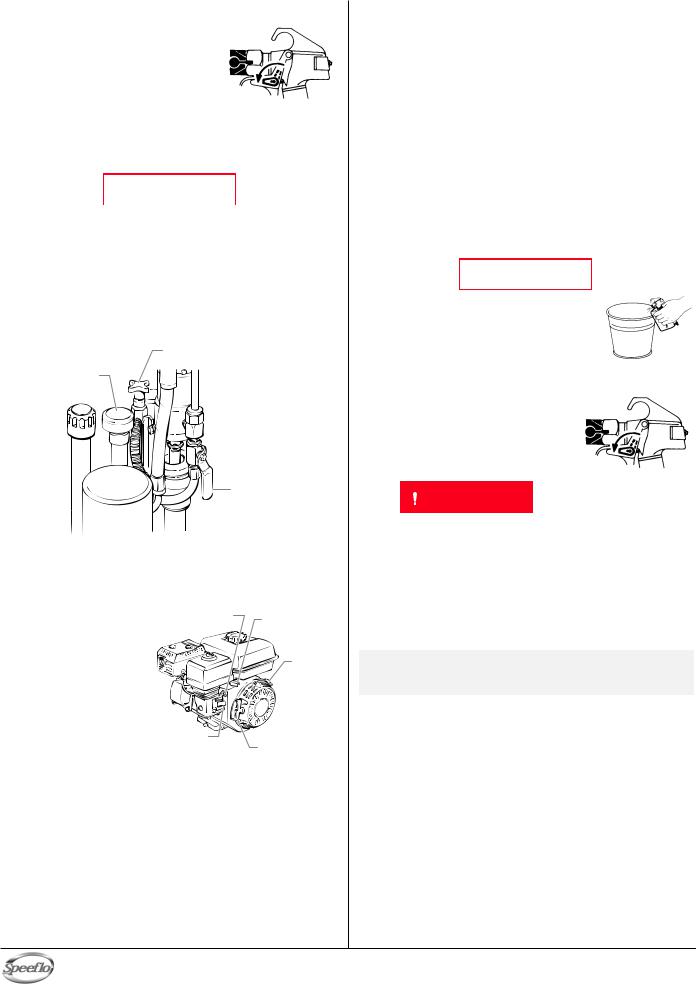
Bleed Valve
Pressure Control
Knob
Hydraulic Shut-Off Valve (in open position)
4.Open the hydraulic shut-off valve located on the hydraulic pressure hose. The handle should be in line with the hose.
5.Open the bleed valve by turning it fully counterclockwise.
6.Start the engine or turn on the electric motor.
a. To start the gas |
Choke Lever |
Throttle |
engine, |
|
|
|
Lever |
|
|
|
• move the fuel valve lever to
the open position,
• move the throttle lever to its middle point,
• move the choke lever to the
closed position
for a cold engine or to the open position for a warm engine,
•turn the engine switch to the ON position, and
•pull the starter rope briskly until the engine starts.
b.To start the electric motor, move the ON/OFF switch to the ON position.
7.Turn the pressure control knob clockwise approximately 1/3 of the way down to increase pressure until the sprayer cycles evenly and solvent flows freely from the bleed hose.
8.Allow the sprayer to run for 15–30 seconds to flush the test fluid out through the bleed hose and into the waste container.
9.Turn off the unit.
a.To turn off the gas engine,
•set the pressure to minimum by turning the pressure control knob fully counterclockwise,
•move the throttle lever to the slow position, and
•turn the engine switch to the OFF position.
b.To turn off the electric motor,
•set the pressure to minimum by turning the pressure control knob fully counterclockwise,
•move the ON/OFF switch to the OFF position.
Preparing to Paint
Before painting, it is important to make sure that the fluid in the system is compatible with the paint that is going to be used.
NOTE: Incompatible fluids and paint may cause the valves to become stuck closed, which would require disassembly and cleaning of the sprayer’s fluid section.
 CAUTION
Always keep the trigger lock on the spray gun in the locked position while preparing the system.
1.Place the siphon hose into a container of the appropriate solvent.
NOTE: If you are spraying a water-based latex, flush with warm, clean water. If you are using any other material, check with the material manufacturer for a compatible solvent.
2.Place the bleed hose into a metal waste container.
3.Set the pressure to minimum by turning the pressure control knob fully counterclockwise.
4.Open the hydraulic shut-off valve located on the hydraulic pressure hose. The handle should be in line with the hose.
5.Open the bleed valve by turning it fully counterclockwise.
6.Start the engine or turn on the electric motor.
a.To start the gas engine,
•move the fuel valve lever to the open position,
•move the throttle lever to its middle point,
•move the choke lever to the closed position for a cold engine or to the open position for a warm engine,
•turn the engine switch to the ON position, and
•pull the starter rope briskly until the engine starts.
b.To start the electric motor, move the ON/OFF switch to the ON position.
7.Turn the pressure control knob clockwise approximately 1/3 of the way down to increase pressure until the sprayer cycles evenly and solvent flows freely from the bleed hose.
8.Allow the sprayer to run for 15–30 seconds to flush the test fluid out through the bleed hose and into the waste container.
9.Turn off the unit.
a.To turn off the gas engine,
•set the pressure to minimum by turning the pressure control knob fully counterclockwise,
•move the throttle lever to the slow position, and
•turn the engine switch to the OFF position.
b.To turn off the electric motor,
•set the pressure to minimum by turning the pressure control knob fully counterclockwise,
•move the ON/OFF switch to the OFF position.
NOTE: Make sure that the spray gun does not have a tip or tip guard installed.
10.Close the bleed valve by turning it fully clockwise.
11.Start the engine or turn on the electric motor.
12.Turn the pressure control knob clockwise approximately 1/3 of the way down to increase pressure.
13.Unlock the gun by turning the gun trigger lock to the unlocked position.
 WARNING
Ground the gun by holding it against the edge of the metal container while flushing. Failure to do so may lead to a static electric discharge, which may cause a fire.
© Titan Tool Inc. All rights reserved. |
7 |
English |
|
|
|
14.Trigger the gun into the metal waste container until the old solvent is gone and fresh solvent is coming out of the gun.
15.Lock the gun by turning the gun trigger lock to the locked position.
16.Set down the gun and increase the pressure by turning the pressure control knob slowly clockwise.
17.Check the entire system for leaks.
If leaks occur, follow the “Pressure |
Trigger lock |
Relief Procedure” in this manual |
in locked position. |
before tightening any fittings or hoses. |
|
18.Follow the “Pressure Relief Procedure” in this manual before changing from solvent to paint.
 WARNING
Be sure to follow the pressure relief procedure when shutting the unit down for any purpose, including servicing or adjusting any part of the spray system, changing or cleaning spray tips, or preparing for cleanup.
Painting
1.Place the siphon hose into a container of paint.
2.Place the bleed hose into a metal waste container.
3.Set the pressure to minimum by turning the pressure control knob fully counterclockwise.
Bleed Valve
Pressure Control
Knob
Hydraulic Shut-Off Valve (in open position)
4.Open the hydraulic shut-off valve located on the hydraulic pressure hose. The handle should be in line with the hose.
5.Open the bleed valve by turning it fully counterclockwise.
6.Start the engine or turn on the electric motor. a. To start the gas engine,
• move the fuel |
Choke Lever |
Throttle |
valve lever to |
|
|
|
Lever |
|
the open |
|
|
|
|
|
position, |
|
Engine |
• move the |
|
|
throttle lever to |
|
Switch |
its middle point, |
|
|
• move the choke |
|
|
lever to the |
|
|
closed position |
Fuel Valve |
|
for a cold |
Starter Rope |
|
engine or to the |
Lever |
open position for a warm engine,
•turn the engine switch to the ON position, and
•pull the starter rope briskly until the engine starts.
b.To start the electric motor, move the ON/OFF switch to the ON position.
7.Turn the pressure control knob clockwise approximately 1/3 of the way down to increase pressure until the sprayer cycles evenly and paint flows freely from the bleed hose.
8.Turn off the unit.
a.To turn off the gas engine,
•set the pressure to minimum by turning the pressure control knob fully counterclockwise,
•move the throttle lever to the slow position, and
•turn the engine switch to the OFF position.
b.To turn off the electric motor,
•set the pressure to minimum by turning the pressure control knob fully counterclockwise,
•move the ON/OFF switch to the OFF position.
9.Remove the bleed hose from the waste container and place it into the container of paint.
10.Close the bleed valve by turning it fully clockwise.
11.Start the engine or turn on the electric motor.
12.Turn the pressure control knob clockwise approximately 1/3 of the way down to increase pressure.
13.Unlock the gun by turning the gun trigger lock to the unlocked position.
 WARNING
Ground the gun by holding it against the edge of the metal container while flushing. Failure to do so may lead to a static electric discharge, which may cause
afire.
14.Trigger the gun into the metal waste container until all air and solvent is flushed from the spray hose and paint is flowing freely. from the gun.
15.Lock the gun by turning the gun trigger lock to the locked position.
16.Turn off the unit.
17.Attach tip guard and tip to the gun as instructed by the tip guard or tip manuals.
|
Trigger lock |
WARNING |
in locked position. |
|
POSSIBLE INJECTION HAZARD. Do not spray without the tip guard in place. Never trigger the gun unless the tip is in either the spray or the unclog position. Always engage the gun trigger lock before removing, replacing or cleaning tip.
18.Start the engine or turn on the electric motor.
19.Increase the pressure by turning the pressure control knob slowly clockwise and test the spray pattern on a piece of cardboard. Adjust the pressure control knob until the spray from the gun is completely atomized.
NOTE: Turning the pressure up higher then needed to atomize the paint will cause premature tip wear and additional overspray.
English |
8 |
© Titan Tool Inc. All rights reserved. |
|
|
|

Pressure Relief Procedure
 WARNING
Be sure to follow the pressure relief procedure when shutting the unit down for any purpose, including servicing or adjusting any part of the spray system, changing or cleaning spray tips, or preparing for cleanup.
1.Lock the gun by turning the gun trigger lock to the locked position.
2.Turn off the unit.
a. To turn off the gas engine,
•set the pressure to minimum by turning the pressure control knob fully counterclockwise,
•move the throttle lever to the slow position, and
Trigger lock
in locked position.
•turn the engine switch to the OFF position. b. To turn off the electric motor,
•set the pressure to minimum by turning the pressure control knob fully counterclockwise,
•move the ON/OFF switch to the OFF position.
3.Close the hydraulic shut-off valve on the hydraulic pressure hose.
4.Unlock the gun by turning the gun trigger lock to the unlocked position.
5.Hold the metal part of the gun firmly to the side of a metal waste container to ground the gun and avoid a build up of static electricity.
6.Trigger the gun to remove any pressure that may still be in the hose.
7.Lock the gun by turning the gun trigger lock to the locked position.
8.Place the bleed hose into the metal waste container.
9.Open the bleed valve by turning it fully counterclockwise.
Cleanup
 WARNING
Special cleanup instructions for use with flammable solvents:
•Always flush spray gun preferably outside and at least one hose length from spray pump.
•If collecting flushed solvents in a one gallon metal container, place it into an empty five gallon container, then flush solvents.
•Area must be free of flammable vapors.
•Follow all cleanup instructions.
 CAUTION
The sprayer, hose, and gun should be cleaned thoroughly after daily use. Failure to do so permits material to build up, seriously affecting the performance of the unit.
 WARNING
Always spray at minimum pressure with the gun nozzle tip removed when using mineral spirits or any other solvent to clean the sprayer, hose, or gun. Static electricity buildup may result in a fire or explosion in the presence of flammable vapors.
1.Follow the “Pressure Relief Procedure” found in the Operation section of this manual.
2.Remove the gun tip and tip guard and clean with a brush using the appropriate solvent.
3.Place the siphon tube into a container of the appropriate solvent.
 CAUTION
Use only compatible solvents when cleaning out oil based enamels, lacquers, coal tar, and epoxies. Check with the fluid manufacturer for the recommended solvent.
4.Place the bleed hose into a metal waste container.
5.Set the pressure to minimum by turning the pressure control knob fully counterclockwise.
Bleed Valve
Pressure Control
Knob
Hydraulic Shut-Off Valve (in open position)
6.Open the hydraulic shut-off valve located on the hydraulic pressure hose. The handle should be in line with the hose.
7.Open the bleed valve by turning it fully counterclockwise.
8.Start the engine or turn on the electric motor.
9.Allow the solvent to circulate through the unit and flush the paint out of the bleed hose into the metal waste container.
10.Turn off the unit.
11.Close the bleed valve by turning it fully clockwise.
12.Start the engine or turn on the electric motor.
 WARNING
Ground the gun by holding it against the edge of the metal container while flushing. Failure to do so may lead to a static electric discharge, which may cause
afire.
13.Trigger the gun into the metal waste container until the paint is flushed out of the hose and solvent is coming out of the gun.
14.Continue to trigger the spray gun into the waste container until the solvent coming out of the gun is clean.
NOTE: For long-term or cold weather storage, pump mineral sprits through the entire system.
15.Follow the “Pressure Relief Procedure” found in the Operation section of this manual.
16.Store the unit in a clean, dry area.
 CAUTION
Do not store the unit under pressure.
© Titan Tool Inc. All rights reserved. |
9 |
English |
|
|
|

Cleaning a Clogged Tip
1.Follow the “Pressure Relief Procedure” in the Operation section of this manual.
2.If the tip clogs, rotate the tip handle 180° until the arrow on the handle is facing the opposite of the spray direction and the handle clicks in the reverse position.
3.Trigger the gun once so that the pressure can blow the clog out. NEVER use the tip in the reverse position for more than ONE trigger pull at a time. This procedure can be repeated until the tip is free of clogging.
 WARNING
The flow from the spray tip is at very high pressure. Contact with any body part may be dangerous. Do not place finger on gun outlet. Do not point the gun at any person. Never operate the spray gun without the proper tip guard.
Maintenance
 WARNING
Before proceeding, follow the Pressure Relief Procedure outlined previously in this manual. Additionally, follow all other warnings to reduce the risk of an injection injury, injury from moving parts or electric shock. Always unplug the sprayer before servicing!
Daily Maintenance
Two daily procedures are required for routine operator maintenance on this unit:
1.Lubricating the upper packings.
2.Cleaning the rock catcher.
Lubricating the Upper Packings
1. Clean out the paint that has seeped past the upper packings into the packing oil reservoir above the fluid section.
2. Fill the packing oil reservoir 1/2 |
|
|
full with Piston Lube (P/N 700- |
Packing Oil |
|
925) supplied by the factory. |
||
Reservoir |
||
This will extend packing life. |
||
|
NOTE: Do not over-fill the reservoir so that it overflows and drips into the paint.
Cleaning the Rock Catcher
1.The rock catcher will clog and must be cleaned at least once a day.
2.Loosen the nut that secures the rock catcher to the siphon tube.
3.Remove the rock catcher from the bottom of the siphon tube.
4.Clean thoroughly with the appropriate solvent.
Nut
Rock
Catcher
Maintaining the Filter Assembly
Clean the filter regularly. Dirty or clogged filters can greatly reduce filtering ability and cause a number of system problems including poor spray patterns, clogged spray tips, etc.
Cleaning
To clean the filter, perform the following procedure.
1.Follow the “Pressure Relief Procedure” found in the Operation section of this manual.
2.Remove the filter cap assembly
and spring.
3. Pull the filter element with ball straight out of the filter body.
4. Clean inside the filter body, filter element with ball, and filter cap assembly using the appropriate solvent.
NOTE: Use care in handling parts as dirt, debris, scratches, or nicks may prevent o-rings or gaskets from sealing.
This filter element filters from the inside out. Be sure to clean the filter element thoroughly on the inside. Soak in solvent to loosen hardened paint or replace.
Inspection
Inspect all parts of the filter assembly before reassembly.
1.Inspect the ball inside the filter element. If the ball has pressure cuts or scratches, replace the filter element.
a.If the ball is cut, remove the PTFE o-ring using an o- ring pick and remove the carbide seat.
b.Check the seat for nicks or grooves. If the seat is damaged, replace.
NOTE: Removal of the PTFE o-ring will damage the o-ring and require replacement.
2.Remove the spring from the spring guide on the filter cap.
a.Measure the length of the spring uncompressed. If it measures less than 3/4” from end to end, replace.
b.Push the spring back onto the spring guide until it “snaps” back into position.
3.Inspect the two PTFE gaskets and the PTFE o-ring for deformity, nicks, or cuts. Replace, if needed.
NOTE: The PTFE gaskets, PTFE o-ring, and spring are packaged in Filter Service Kit P/N 930-050.
Reassembly
After cleaning and inspecting all parts, reassemble the filter.
1.Place the carbide seat into the filter body. Make sure the beveled side of the seat is facing up.
2.Place the PTFE o-ring into the groove on the outer diameter of the carbide seat.
3.Place the filter element with ball into the filter body.
NOTE: The top and bottom of the filter element with ball are identical.
4.Push the spring back onto the spring guide of the filter cap until it “snaps” back into position, if not already done.
5.Place the thin PTFE gasket onto the step at the top of the filter body.
6.Place the thick PTFE gasket onto the top of the thin gasket.
7.Tighten the filter cap assembly onto the filter body.
English |
10 |
© Titan Tool Inc. All rights reserved. |
|
|
|
Maintaining the Hydraulic System
 CAUTION
Use of Speeflo's Coolflo™ Hydraulic Fluid is mandatory in the PowrTwin hydraulic system. Do not use any other hydraulic fluid. Use of any other hydraulic fluid may seriously damage the hydraulic system and will void the warranty.
1.Check the hydraulic fluid daily. It should be at the “Full” mark on the dipstick. If it is low, add only Speeflo Coolflo™ Hydraulic Fluid (P/N 430-361). Never add or change hydraulic fluid except in a clean, dust-free area. Contamination of the hydraulic fluid will shorten hydraulic pump life and may void warranty.
Hydraulic Fluid 

Cap/Dipstick
"Full" Mark 

Hydraulic
Filter
2.Change the hydraulic fluid every twelve months. Drain the old fluid from the tank and fill with 5 quarts of Speeflo Coolflo™ Hydraulic Fluid. Start the unit at just enough pressure to operate the fluid section. Run the unit at this low pressure for at least 5 minutes. This removes air from the system. Check the fluid level after this procedure.
3.The hydraulic system has an external, replaceable hydraulic filter. Change the filter every twelve months.
4.The hydraulic pump should not be serviced in the field. If service on the hydraulic pump is required, it must be returned to Speeflo.
Maintaining the Fluid Section
If the sprayer is going to be out of service for an extended period of time, it is recommended that following cleanup, a kerosene and oil mixture be introduced as a preservative. Packings may tend to dry out from lack of use. This is particularly true of the upper packing set for which upper packing lubricant Piston Lube (P/N 700-925) is recommended in normal usage.
If the sprayer has been out of service for an extended period of time, it may be necessary to prime the suction by pouring some of the paint solvent into the siphon tube to restart. It is extremely important that the threads on the siphon hose coupling are properly sealed. Any air leakage will produce erratic operation of the sprayer and may damage the system. The up and the down strokes should be approximately equal in time (one should not be faster than the other). A fast up or down stroke may indicate air in the system or malfunctioning valve or seats (see the Troubleshooting section).
Basic Engine Maintenance (gas engine)
•For detailed engine maintenance and technical specifications refer to the separate gasoline engine manual.
•All service to the engine should be performed by an authorized Honda Power Equipment dealer. To locate a dealer in your area, look in the Yellow Pages of your telephone directory under Gasoline Engines, Garden & Lawn Equipment & Supplies, Lawn Mowers, etc.
•The Honda engine is warranted exclusively by American Honda Motor Co., Inc.
•Use a premium quality motor oil certified to meet or exceed U.S. Automotive requirement SG.or SF. SAE 10W30 is recommended for general all temperature use. Other viscosities may be required in other climates.
•Use only a (NGK) BP6ES or BPR6E spark plug. Gap the plug to 0.028 to 0.031 In. (0.7 to 0.8 mm) Always use a spark plug wrench.
Daily
1.Check engine oil level, and fill as necessary.
2.Check gasoline level, and fill as necessary.
 WARNING
Always follow the fueling procedure outlined earlier in this manual.
First 20 Hours
1. Change engine oil.
Every 100 Hours
1.Change engine oil.
2.Clean the sediment cup.
3.Clean and re-gap the spark plug.
4.Clean the spark arrestor.
Weekly
1.Remove the air filter cover and clean the element. In very dusty environments, check the filter daily. Replace the element as needed. Replacement elements can be purchased from your local Honda dealer.
Engine Operation and Service
1.Clean and oil air filter pad on gasoline engine every 25 hours or once weekly. Do not permit the air intake screen around the fly wheel of the gas engine to load up with paint or trash. Clean it regularly. The service life and efficiency of the gas engine model depends upon keeping the gasoline engine running properly. Change the oil in the engine every 100 hours. Failure to observe this may result in engine overheating. Consult the engine manufacturer's service manual provided.
2.To conserve fuel, service life, and efficiency of the unit, always operate the gasoline engine at the lowest RPM at which it runs smoothly without laboring and delivers the amount required for the particular painting operation. Higher RPM does not produce higher working pressure. The gasoline engine is connected to the hydraulic pump by a pulley combination designed to produce full paint delivery of 1.2 GPM at maximum RPM.
3.The warranty on gasoline engines or electric motors is limited to the original manufacturer.
© Titan Tool Inc. All rights reserved. |
11 |
English |
|
|
|
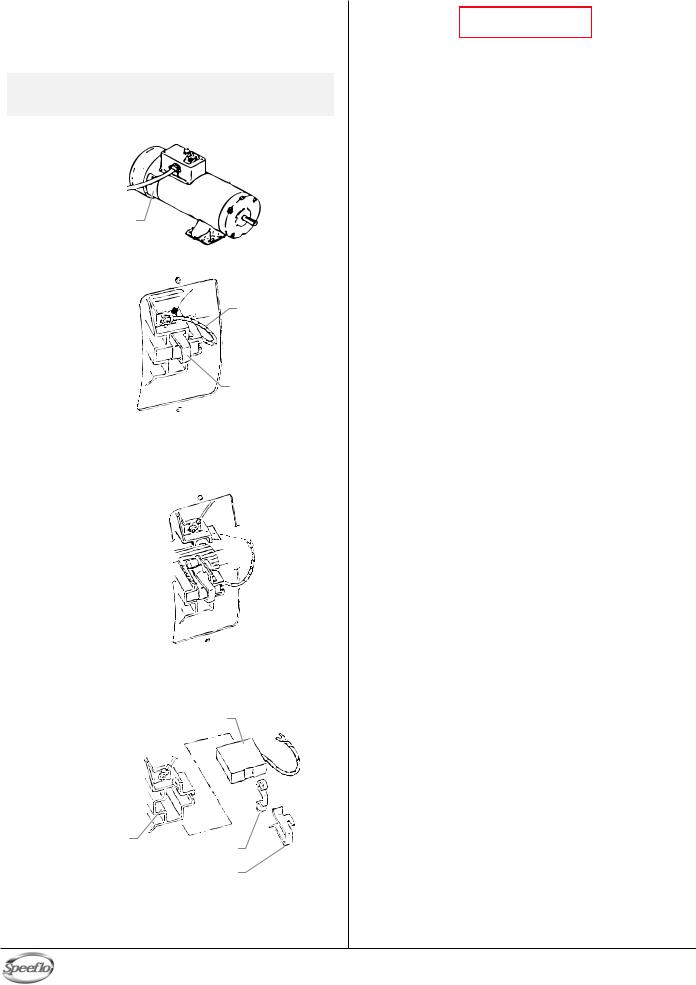
Replacing the Motor Brushes (electric motor)
Perform this procedure using Motor Brush Kit P/N 978-050. The kit consists of two brushes, two springs, and two clips.
NOTE: Brushes should be replaced when they are worn to less than 1/2 inch. Check and replace both brushes at the same time.
1. Remove both inspection covers on the motor.
Inspection
Cover
2. Push in the spring clip to unhook it, then pull it out..
Terminal Screw

 Brush Lead
Spring Clip
3.Loosen the terminal screw. Pull the brush lead away, but leave the motor lead in place. Remove the brush and spring.
4.Inspect the commutator for burning, excessive pitting or gouging. A black color on the commutator is normal.
Commutator

5.Install the new brush so its lead slides in the long slot of the brush holder. Push the terminal under the terminal screw washer. Ensure the motor lead is still connected at the screw. Tighten the screw.
Brush
Terminal Screw
Brush Holder
Spring
Spring Clip
6.Place the spring on the brush as shown above. Push in and hook the spring clip. Repeat this procedure for the other side.
7.Reinstall both inspection covers.
 WARNING
If electric motor overloads and stops running, IMMEDIATELY turn the motor off and follow the Pressure Relief Procedure in the Cleanup section of this manual. Wait until the motor cools (approximately 30 minutes). Then push in the bubble top, manual reset button, turn the motor on and pressurize the system.
For CSA approved units only: The ON/OFF switch is also the RESET!
English |
12 |
© Titan Tool Inc. All rights reserved. |
|
|
|

Airless Gun
Problem
Spitting gun
Gun will not shut off
Gun does not spray
Fluid Section
Problem
Pump delivers on upstroke only or goes up slowly and down fast (commonly called downstroke dive)
Pump delivers on down stroke only or goes up fast and down slowly
Pump moves up and down fast, delivering material
Pump moves up and down slowly when spray gun is shut off
Not enough fluid pressure at gun
Pump chatters on up or down stroke
Troubleshooting
Cause |
Solution |
|||||||
1. |
Air in system |
1. |
Inspect connections for air leaks. |
|||||
2. |
Dirty gun |
2. |
Disassemble and clean. |
|||||
3. |
Needle assembly out of adjustment |
3. |
Inspect and adjust. |
|||||
4. |
Broken or chipped seat |
4. |
Inspect and replace. |
|||||
|
|
|
|
|
|
|
|
|
1. |
Worn or broken needle & seat |
1. |
Replace. |
|||||
2. |
Needle assembly out of adjustment |
2. |
Adjust. |
|||||
3. |
Dirty gun |
3. |
Clean. |
|||||
|
|
|
|
|
|
|
|
|
1. |
No paint |
1. |
Check fluid supply. |
|||||
2. |
Plugged filter or tip |
2. |
Clean. |
|||||
3. |
Broken needle in gun |
3. |
Replace. |
|||||
Cause |
Solution |
|||||||
1.Lower foot valve ball is not seating due to trash or wear
2.Material too viscous to siphon.
3.Air leaking in on siphon side or damaged siphon hose. Siphon may be too small for heavy material.
1.Upper ball is not seating due to trash or wear
2.Lower packing set is worn
1.Material container is empty or material is too thick to flow through siphon hose
2.Bottom ball stuck to foot valve seat
3.Siphon hose is kinked or loose
1.Loose connections. Bleed valve is open partially or bleed valve is worn. Lower packing seat is worn.
2.Upper and/or lower ball not seating
1.Spray tip is worn
2.Outlet filter or gun filter is clogged
3.Low voltage and/or inadequate amperage
4.Hose size or length is too small or too long
1.Solvent has caused upper packing to swell
1.Remove foot valve assembly. Clean and inspect. Test foot valve by filling with water; if ball fails to seal the seat, replace ball.
2.Thin material — contact manufacturer for proper thinning procedures.
3.Tighten all connections between pump and paint container. If damaged, replace. Switch to larger diameter siphon set.
1.Check upper seat and ball with water. If ball fails to seal, replace seat.
2.Replace packing set if worn.
1.Refill with new material. If too thick, remove siphon hose, immerse fluid section in material, and start pump to prime. Add thinner to material. Change to bigger siphon set. Open bleed valve to remove air and restart pump.
2.Remove foot valve. Clean ball and seat.
3.Straighten.
1.Check all connections between pump and gun. Tighten as necessary. If material is flowing from bleed hose, close bleed valve or replace, if necessary. Should none of the above be evident, replace lower packing.
2.Reseat balls by cleaning.
1.Replace.
2.Clean or replace filter.
3.Check electrical service. Correct as required.
4.Increase hose size to minimize pressure drop through hose and/or reduce hose length.
1. Replace packing.
© Titan Tool Inc. All rights reserved. |
13 |
English |
|
|
|
|
|
|
|
|
|

Troubleshooting
Hydraulic Motor
Problem |
Cause |
Oil motor stalls at bottom (no |
1. Fluid pump piston seat unthreaded |
unusual heat problems) |
|
2.Valve sticking or oil motor trip rod shifter assembly separated
Oil motor stalls at top (no |
1. |
Valve sticking |
unusual heat problems) |
|
|
|
2. |
Broken spring retainer (valve rod |
|
|
assembly) |
|
3. |
Broken spring or valve rod |
|
4. |
Air in hydraulic motor |
|
|
|
5. |
Air in fluid pump |
||
|
|
|
|
|
|
|
Low pressure (okay on down |
1. |
Blown piston seal |
||||
stroke, sluggish on up.stroke — |
|
|
|
|
||
high heat) |
|
|
|
|
||
NOTE: Engine labors on |
|
|
|
|
||
|
upstroke, idles back |
|
|
|
|
|
|
at stall on the down |
|
|
|
|
|
|
stroke. |
2. |
Cracked piston |
|||
|
|
|
||||
|
|
|
|
|
|
|
Low pressure (both strokes - |
1. |
Blown center o-rings on spool valve |
||||
high heat) |
2. |
Bad hydraulic pump |
||||
NOTE: Engine labors at stall |
|
|
|
|
||
|
on both strokes. |
|
|
|
|
|
Solution
1.If connecting rod is okay, remove cylinder head plug and pop valve down. Replace plug and start machine. If machine cycles up and stops at bottom again, then problem is piston seat on fluid pump. Check piston seat. Repair or replace as necessary. If piston seat is okay and problem does not change, check oil motor.
2.Remove valve and check for scratches and rough movement when sliding it up and down. Replace valve and spool in this condition. Check trip rod for possible separation.and spool in this condition. Check trip rod for possible separation.
1.Remove valve and check for scratches and rough movement when sliding it up and down. Replace valve and spool in this condition.
2.Replace valve rod assembly.
3.Replace valve rod assembly.
4.Reset valve. Purge Air, generally accomplished by low pressure cycling of motor/pump assembly for 5–10 minutes. Check for causes of air introduction:
•Loose fittings in tank.
•Loose fittings on hydraulic pump.
•Loose hose connections.
•Low oil in reservoir.
5.Stall at top can occur randomly when fluid pump picks up air. Reset valve. Avoid air in the fluid pump.
1.Before dismantling oil motor, start machine. With pump cycling under pressure, touch the hydraulic cylinder and the head to see if cylinder or head gets hotter. This will help determine if piston seal is blown or piston nut is broken. If heat is on the head, check the o-rings on spool valve.
2.Dismantle oil motor and check piston seals cylinder bore and piston nut. Pay special attention to piston nut. It can be cracked and not show externally.
1.Before dismantling oil motor, start machine. With pump cycling under pressure, touch the head to see if the head becomes hotter. This will help determine if center o-ring is blown on spool valve. If hot, remove and replace o-ring.
2.Replace hydraulic pump.
|
English |
14 |
© Titan Tool Inc. All rights reserved. |
|
|
|
|

Troubleshooting
Spray Patterns
Problem |
Cause |
Solution |
||||||
Tails |
1. |
Inadequate fluid delivery |
1. |
Fluid not atomizing correctly: |
||||
|
|
|
|
|
|
Increase fluid pressure. Change to smaller |
||
|
|
|
|
|
|
tip orifice size. Reduce fluid viscosity. |
||
|
|
|
|
|
|
Reduce hose length. Clean gun and |
||
|
|
|
|
|
|
filter(s). Reduce number of guns using |
||
|
|
|
|
|
|
pump. |
||
|
|
|
|
|
|
|
|
|
Hour glass |
1. |
Inadequate fluid delivery |
1. |
Same as above. |
||||
Distorted |
1. Plugged or worn nozzle tip |
1. Clean or replace nozzle tip. |
Pattern expanding and |
1. |
Suction leak |
1. |
Inspect for suction hose leak. |
||||
contracting (surge) |
2. |
Pulsating fluid delivery |
2. |
Change to a smaller tip orifice size. Install |
||||
|
|
|
|
|
|
pulsation dampener in system or drain |
||
|
|
|
|
|
|
existing one. Reduce number of guns using |
||
|
|
|
|
|
|
pump. Remove restrictions in system; clean |
||
|
|
|
|
|
|
tip screen if filter is used. |
||
|
|
|
|
|
|
|
|
|
Round pattern |
1. |
Worn tip |
1. |
Replace tip. |
||||
|
|
2. |
Fluid too heavy for tip |
2. |
Increase pressure. Thin material. Change |
|||
|
|
|
|
|
|
nozzle tip. |
||
© Titan Tool Inc. All rights reserved. |
15 |
English |
|
|
|
|
|
|
|
|
|

Parts Lists and Service Instructions
Main Assembly
|
8 |
|
9 |
1 |
|
2 |
|
3 |
10 |
|
|
4 |
4 |
|
|
5 |
|
6
11
7
Item |
Part # |
Description |
Quantity |
Item |
Part # |
Description |
Quantity |
1 |
236-144 |
Motor/pump assembly.............................. |
1 |
8 |
---------- |
Hydraulic system...................................... |
1 |
2 |
228-002 |
Adapter..................................................... |
1 |
9 |
449-125 |
Belt, "V" ................................................... |
1 |
3 |
200-555 |
Swivel adapter.......................................... |
1 |
10 |
506-278 |
Convertokit, 6.5 HP, Honda, gasoline |
|
4 |
840-211 |
Bleed hose assembly w/valve.................. |
1 |
|
|
(gas model) .............................................. |
1 |
5 |
930-514 |
Filter assembly ......................................... |
1 |
11 |
103-830 |
Siphon hose assembly, 1" x 4.5".............. |
1 |
6 |
449-927 |
Cart assembly .......................................... |
1 |
12 |
506-276 |
Convertokit, DC electric, 115V |
|
7 |
449-934 |
Belt guard assembly................................. |
1 |
|
|
(electric model, not shown) ...................... |
1 |
Bleed Hose Assembly with Valve (P/N 840-211)
1
2 
3
4
Item |
Part # |
Description |
Quantity |
1 |
944-028 |
Bleed valve............................................... |
1 |
2 |
818-014 |
Elbow, 90º ................................................ |
1 |
3 |
539-078 |
Hose assembly......................................... |
1 |
4 |
103-117 |
Tube ......................................................... |
1 |
5 |
103-111 |
Bleed line assembly |
|
|
|
(includes items 3 and 4)........................... |
1 |
English |
16 |
© Titan Tool Inc. All rights reserved. |
|
|
|
|
|
|

Cart Assembly (P/N 449-927)
1
 10
10
11
12
13  14
14  15
15 

 16
16 
 17
17 
 18
18
2
3
4
5
|
19 |
|
6 |
20 |
|
7 |
||
21 |
||
|
||
8 |
|
|
|
9 |
|
|
|
|
|
|
Item |
Part # |
Description |
Quantity |
|
Item |
Part # |
Description |
Quantity |
|
||||||||
1 |
590-502 |
Handle .................................................. |
1 |
|
12 |
590-504 |
Sleeve................................................... |
2 |
2 |
862-460 |
Screw.................................................... |
1 |
|
13 |
590-506 |
Washer.................................................. |
2 |
3 |
459-051 |
Motor/pump bracket.............................. |
1 |
|
14 |
856-921 |
Screw.................................................... |
4 |
4 |
590-503 |
Axle....................................................... |
1 |
|
15 |
856-002 |
Washer.................................................. |
4 |
5 |
449-120 |
Spacer (long) ........................................ |
1 |
|
16 |
862-002 |
Lock washer.......................................... |
2 |
6 |
670-109 |
Wheel.................................................... |
2 |
|
17 |
862-428 |
Screw.................................................... |
2 |
7 |
870-004 |
Washer.................................................. |
2 |
|
18 |
449-052 |
Spacer .................................................. |
1 |
8 |
590-100 |
Retaining ring........................................ |
2 |
|
19 |
449-145 |
Spacer (short)....................................... |
1 |
9 |
449-060 |
Frame ................................................... |
1 |
|
20 |
862-411 |
Nut ........................................................ |
1 |
10 |
590-508 |
Roll pin.................................................. |
2 |
|
21 |
862-001 |
Flat washer ........................................... |
1 |
11 |
590-507 |
Snap button .......................................... |
2 |
|
|
|
|
|
|
|
|
|
|
|
|
|
|
Belt Guard Assembly (P/N 449-934)
Item |
Part # |
Description |
Quantity |
1 |
---------- |
Belt guard ............................................. |
1 |
2 |
858-636 |
Screw.................................................... |
2 |
3 |
858-002 |
Lockwasher........................................... |
2 |
4 |
449-187 |
Clip........................................................ |
1 |
5 |
862-411 |
Nut ........................................................ |
1 |
6 |
862-001 |
Washer.................................................. |
1 |
1 
2
3
4
5
6
© Titan Tool Inc. All rights reserved. |
17 |
English |
|
|
|
|
|
|

Hydraulic System
1 |
31 |
||||||||||||||||||
2 |
32 |
||||||||||||||||||
33 |
|||||||||||||||||||
3 |
|||||||||||||||||||
34 |
|||||||||||||||||||
4 |
|||||||||||||||||||
|
|
|
|
|
|
|
|
|
|
|
|
|
|
|
|
|
35 |
||
5 |
|
|
|
|
|
||||||||||||||
|
|
||||||||||||||||||
|
|||||||||||||||||||
|
36 |
||||||||||||||||||
6 |
37 |
||||||||||||||||||
7 |
38 |
||||||||||||||||||
8 |
|
|
|
|
|
|
|
|
|
|
|
|
|
|
|
|
|
|
|
9 |
|
|
|
|
|
39 |
|||||||||||||
|
|||||||||||||||||||
|
|
|
|
|
|
|
|
|
|
|
|
|
|
|
|
|
|
||
10 |
|
|
|
|
|
|
|
|
|
|
|
|
|
|
|
|
|
|
|
11 |
|
|
|
|
|
|
|
|
|
|
|
|
|
|
|
|
|
|
|
12 |
|
|
|
|
|
|
|
|
|
|
|
|
|
|
|
|
|
|
|
|
|
|
|
|
|
|
|
|
|
|
|
|
|
|
|
|
|
||
13 |
|
|
|
|
|
|
|
|
|
|
|
|
|
|
|
|
|
40 |
|
14 |
|
|
|
|
|
|
|
||||||||||||
|
|
|
|||||||||||||||||
|
|
|
|
|
|
|
|
|
|
|
|
|
|
|
|
|
|
||
15 |
|
|
|
|
|
|
|
|
|
|
|
|
|
|
|
|
|
|
|
16 |
|
|
|
|
|
|
|
|
|
|
|
|
|
|
|
|
|
|
|
17 |
9 |
|
|
||||||||||||||||
18 |
|
|
|||||||||||||||||
10 |
|
|
|||||||||||||||||
19 |
|
|
|||||||||||||||||
|
|
|
|
|
|
|
|
|
|
|
|
|
|
|
|
|
|
||
20 |
|
|
|
|
|
|
|
|
|
|
|
|
|
|
|
|
|
|
|
21 |
41 |
||||||||||||||||||
22 |
|
|
|
|
|
|
|
|
|
|
|
|
|
|
|
|
|
42 |
|
|
|
|
|
|
|
|
|
|
|
|
|
|
|
|
|
|
|||
23 |
|
|
|
|
|
|
|
|
|
|
|||||||||
|
|
|
|
|
|
|
|
|
43 |
||||||||||
|
|
|
|
||||||||||||||||
24 |
|
|
|
|
|
|
|
|
|
|
|
44 |
|||||||
|
|
|
|
|
|
|
|||||||||||||
25 |
|
|
|
|
|
|
|
|
|
|
|
|
|
|
|
|
|
|
|
26 |
|
|
|
|
|
|
|
|
|
|
|
|
|
|
|
28 |
|
|
|
|
|
|
|
|
|
|
|
|
|
|
|
|
|
|
|
|
|||
27 |
|
|
|
|
|
|
|
|
|
|
|
|
|||||||
|
|
|
|
|
|
|
|||||||||||||
28 |
|
|
|
|
45 |
||||||||||||||
|
|
|
|
||||||||||||||||
29 |
24 |
|
|
||||||||||||||||
|
|
|
|||||||||||||||||
|
25 |
|
|
|
|
|
|
|
|
|
|
|
|
|
|
|
|
|
|
30 |
|
|
|
|
|
|
|
|
|
|
|
|
|
|
|
|
|
|
|
Item |
Part # |
Description |
Quantity |
1 |
313-755 |
Knob decal ............................................... |
1 |
2 |
862-414 |
Set screw.................................................. |
1 |
3 |
448-243 |
Pressure control knob .............................. |
1 |
4 |
860-520 |
Set screw.................................................. |
1 |
5 |
449-195 |
Pulley/fan assembly ................................. |
1 |
6 |
448-494 |
Key, pump (.156 x .156 x 13/16) ................. |
1 |
7 |
449-752 |
Hydraulic pump ........................................ |
1 |
8 |
431-042 |
Tube connector ........................................ |
1 |
9 |
858-636 |
Screw, HH ................................................ |
8 |
10 |
858-002 |
Lock washer ........................................... |
10 |
11 |
325-031 |
O-ring ....................................................... |
1 |
12 |
448-231 |
Return hose assembly ............................. |
1 |
13 |
451-029 |
Fitting........................................................ |
1 |
14 |
449-616 |
Tank cover................................................ |
1 |
15 |
858-609 |
Clinch nut ................................................. |
1 |
16 |
858-621 |
Socket screw............................................ |
2 |
17 |
859-001 |
Washer ..................................................... |
2 |
18 |
858-624 |
Screw ....................................................... |
2 |
19 |
449-605 |
Tank gasket .............................................. |
1 |
20 |
112-208 |
Nipple ....................................................... |
1 |
21 |
472-500 |
Elbow, street............................................. |
1 |
22 |
448-208 |
Inlet screen............................................... |
1 |
23 |
449-623 |
Hydraulic tank........................................... |
1 |
24 |
862-411 |
Flex lock nut ............................................. |
2 |
25 |
862-001 |
Flat washer............................................... |
6 |
26 |
862-002 |
Lock washer ............................................. |
4 |
27 |
449-212 |
Plug .......................................................... |
1 |
28 |
862-493 |
Screw, HH ................................................ |
2 |
29 |
862-496 |
Tap bolt..................................................... |
1 |
30 |
449-982 |
Shield ....................................................... |
1 |
31 |
192-228 |
Elbow........................................................ |
1 |
32 |
449-126 |
Hose clamp .............................................. |
1 |
33 |
420-250 |
Tubing, PTFE........................................... |
1 |
34 |
448-246 |
Pressure hose assembly.......................... |
1 |
35 |
192-051 |
Elbow........................................................ |
1 |
36 |
101-205 |
Ground lug................................................ |
1 |
37 |
451-220 |
Hydraulic filter........................................... |
1 |
38 |
449-609 |
Hydraulic by-pass..................................... |
1 |
39 |
449-626 |
Hydraulic fluid cap/dipstick....................... |
1 |
40 |
449-614 |
Tube assembly ......................................... |
1 |
41 |
862-438 |
Thumb screw............................................ |
1 |
42 |
862-402 |
Acorn nut.................................................. |
1 |
43 |
449-107 |
Mounting plate retainer ............................ |
1 |
44 |
449-135 |
Spacer ...................................................... |
1 |
45 |
862-480 |
Screw, HH ................................................ |
1 |
46 |
451-121 |
Elbow (not shown).................................... |
1 |
47 |
941-555 |
Ball valve (not shown).............................. |
1 |
Torque and Sealant Guide
Item Description
4 Use blue Loctite on threads
4 Torque to 10 ft./lbs. (13.5 N/m)
8 Use hydraulic sealant
13 Use hydraulic sealant
16 Use blue Loctite on threads
16 Torque to 8 FT/LBS (11 N/m)
18 Torque to 8 FT/LBS (11 N/m)
20Use hydraulic sealant
21Use hydraulic sealant
22Use hydraulic sealant
28Torque to 15 FT/LBS (20,5 N/m)
29Torque to 15 FT/LBS (20,5 N/m)
37Torque to 20 FT/LBS (28 N/m)
45Torque to 15 FT/LBS (20,5 N/m)
English |
18 |
© Titan Tool Inc. All rights reserved. |
|
|
|
|
|
|

DC — Electric Convertokit (P/N 506-276)
|
7 |
||||||||||||||
|
8 |
||||||||||||||
|
9 |
||||||||||||||
|
|
|
|
|
|
|
|
|
|
|
|
2 |
|
||
|
|
|
|
|
|
|
|
||||||||
|
|
|
|
|
|
|
|
|
|
|
3 |
|
|||
|
|
|
|
|
|
|
|||||||||
1 |
|
|
|
|
|
|
|
|
|
4 |
10 |
||||
|
|
|
|
|
|||||||||||
|
|
|
|
|
|
|
|
|
|
|
|
|
|
||
|
|
|
|
|
|
|
|
|
|
|
|
|
|
||
|
|
|
|
|
|||||||||||
|
|
|
|||||||||||||
2 |
|
|
11 |
||||||||||||
|
|
|
|
|
|
|
|
|
|
|
|
|
|
|
|
3 |
|
|
|
|
|
|
|
|
|
|
|
|
|
|
12 |
4 |
|
|
|
|
|
|
|
|
|
||||||
|
|
4 |
|||||||||||||
|
|
|
|
|
|
|
|
|
|
|
|
|
|||
5 |
|
|
|
|
|
|
|||||||||
|
|
||||||||||||||
|
|
|
|
|
|
|
|
|
|
|
|
|
|
|
|
|
|
|
|
|
|
|
|
13 |
|||||||
|
|
|
|
||||||||||||
|
14 |
||||||||||||||
4
|
|
6 |
|
|
|
|
|
|
|
Item |
Part # |
Description |
Quantity |
|
Item |
Part # |
Description |
Quantity |
|
|
|||||||||
1 |
506-259 |
Cover........................................................ |
|
1 |
|
10 |
977-228 |
Pulley........................................................ |
1 |
2 |
860-501 |
Nut stop.................................................... |
|
4 |
|
11 |
590-068 |
Handle grip............................................... |
1 |
3 |
860-002 |
Lock washer ............................................. |
|
4 |
|
12 |
335-017 |
Handle ...................................................... |
1 |
4 |
860-004 |
Flat washer............................................... |
|
8 |
|
13 |
860-552 |
Screw ....................................................... |
2 |
5 |
459-016 |
Motor shaft shield....................................... |
|
|
|
14 |
449-989 |
Mount plate............................................... |
1 |
6 |
860-535 |
Screw ....................................................... |
|
2 |
|
15 |
506-255 |
Rectifier (not shown) ................................ |
1 |
7 |
506-257 |
Circuit breaker reset................................. |
|
1 |
|
16 |
506-258 |
Fan (not shown) ....................................... |
1 |
8 |
506-260 |
ON/OFF switch......................................... |
|
1 |
|
17 |
449-125 |
Belt, "V" |
|
9 |
978-350 |
Motor, |
|
|
|
|
|
(not shown, not part of assembly) |
|
|
|
DC-Electric, 2 HP, 50 / 60 Hz, 115 V ....... |
1 |
|
|
|
|
|
|
|
|
|
|
|
|
|
|
|
|
© Titan Tool Inc. All rights reserved. |
19 |
English |
|
|
|
|
|
|
|
|
|
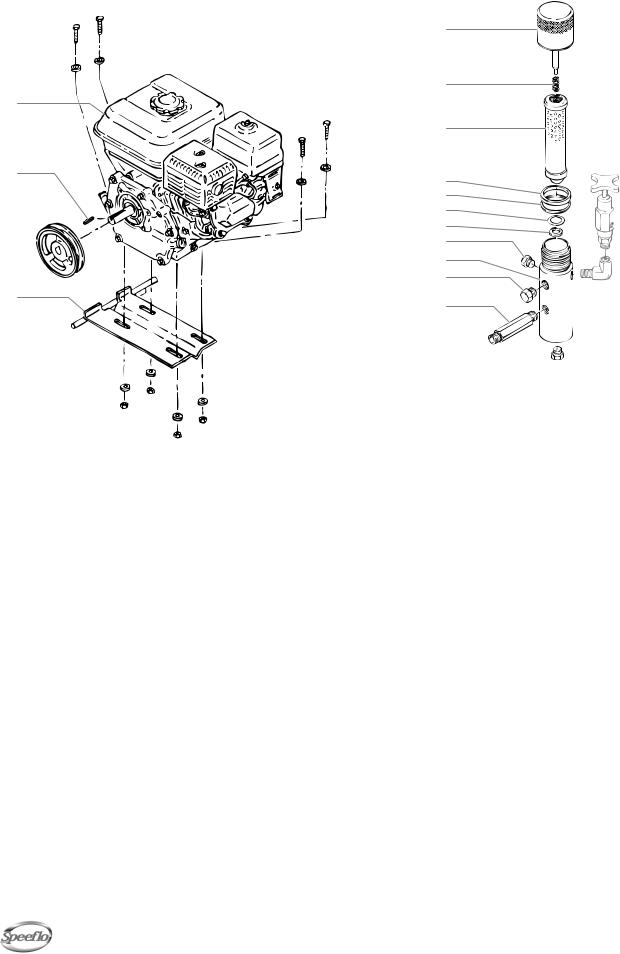
Gas Convertokit (P/N 506-278) |
|
|
Filter Assembly |
|
|
|
|
|
||||||||||||
1 |
|
|
|
|
|
|
|
|
|
|
|
1 |
|
|
|
|
|
|
|
|
|
|
|
|
|
|
|
|
|
|
|
|
|
|
|
|
|
|
|
||
2 |
|
|
|
|
|
|
|
|
|
|
|
2 |
|
|
|
|
|
|
|
|
|
|
|
|
|
|
|
|
|
|
|
|
|
|
|
|
|
|
|
||
|
|
|
|
|
|
|
|
|
|
|
|
|
|
|
|
|
|
|
|
|
3 |
|
|
|
|
|
|
|
|
|
|
|
|
|
|
|
|
|
|
|
|
|
|
|
|
|
|
|
|
|
|
|
|
3 |
|
|
|
|
|
|
|
|
4 |
|
|
|
|
|
|
|
|
|
|
|
4 |
|
|
|
|
|
|
|
|
|
|
|
|
|
|
|
|
|
|
|
|
|
|
|
|
|
|
|
|
|
|
|
|
|
|
|
|
|
|
|
|
|
5 |
|
|
|
|
|
|
|
|
|
|
|
|
|
|
|
|
|
|
|
|
6 |
|
|
|
|
|
|
|
|
|
|
|
|
|
|
|
|
|
|
|
|
7 |
|
|
|
|
|
|
|
|
5 |
|
|
|
|
|
|
|
|
|
|
|
8 |
|
|
|
|
|
|
|
|
|
|
|
|
|
|
|
|
|
|
|
|
|
|
|
|
|
|
|
||
|
|
|
|
|
|
|
|
|
|
|
|
9 |
|
|
|
|
|
|
|
|
|
|
|
|
|
|
|
|
|
|
|
|
10 |
|
|
|
|
|
|
|
|
6 |
|
|
|
|
|
|
|
|
|
|
|
11 |
|
|
|
|
|
|
|
|
|
|
|
|
|
|
|
|
|
|
|
|
|
|
|
|
|
|
|
|
|
|
|
|
|
|
|
|
|
|
|
|
|
10 |
|
|
|
|
|
|
|
|
2 |
|
|
|
|
|
|
|
|
|
|
|
|
930-514 930-515 930-516 |
|||||||
|
|
|
|
|
|
|
|
|
|
|
|
|
|
|||||||
|
|
|
|
|
|
|
|
|
Item |
Part # |
Description |
|
|
Qty. |
Qty. |
Qty. |
||||
|
|
|
|
|
|
|
|
|
|
|||||||||||
7 |
|
|
|
|
|
|
|
|
|
|
1 |
930-937 |
Filter cap assembly ...... |
1............ |
1 ........... |
1 |
||||
|
|
|
|
|
|
|
|
|
|
|
2 |
930-020 |
Spring |
........................... |
|
|
............1 |
...........1 |
1 |
|
|
|
|
|
|
|
|
|
|
|
|
3 |
930-005 |
Filter element, |
|
|
|
|
|
||
|
|
|
|
|
|
|
|
|
|
|
|
|
5 M, w/ball .................... |
|
|
1 |
|
|
||
Item |
Part # |
Description |
Quantity |
|
|
930-006 |
Filter element, |
|
|
|
|
|
||||||||
|
|
|
50 M, w/ball ................................ |
|
|
|
1 |
|
||||||||||||
1 |
|
860-552 |
Screw ....................................................... |
4 |
|
|
930-007 |
Filter element, |
|
|
|
|
|
|||||||
2 |
|
860-004 |
Flat washer............................................... |
8 |
|
|
|
100 M, ............................................w/ball |
|
|
|
|
1 |
|||||||
3 |
|
764-020 |
Engine, gas 6.5 HP, Honda...................... |
1 |
|
4 |
920-006 |
Gasket, ....PTFE (thick) |
1............ |
1 ........... |
1 |
|||||||||
4 |
|
980-307 |
Key ........................................................... |
1 |
|
5 |
920-070 |
Gasket, .....PTFE (thin) |
1............ |
1 ........... |
1 |
|||||||||
5 |
|
449-984 |
Pulley........................................................ |
1 |
|
6 |
891-193 |
O-ring, ................PTFE |
|
|
1............ |
1 ........... |
1 |
|||||||
6 |
|
449-219 |
Mounting plate, gas eng........................... |
1 |
|
7 |
180-909 |
Seat, tungsten carbide .1............ |
1 ........... |
1 |
||||||||||
7 |
|
860-502 |
Stop nut.................................................... |
4 |
|
8 |
227-027 |
Pipe plug ...................... |
|
|
1............ |
1 ........... |
1 |
|||||||
8 |
|
449-125 |
Belt, "V" (not shown, not part of assembly) |
|
9 |
930-920 |
Filter body..................... |
|
|
1............ |
1 ........... |
1 |
||||||||
|
|
|
|
|
|
|
|
|
|
|
10 |
227-033 |
Pipe plug ...................... |
|
|
2............ |
2 ........... |
2 |
||
|
|
|
|
|
|
|
|
|
|
|
11 |
191-324 |
Hex nipple .................... |
|
|
1............ |
1 ........... |
1 |
||
|
|
|
|
|
|
|
|
|
|
|
Filter Service Kit (P/N 930-050) |
|
|
|||||||
|
|
|
|
|
|
|
|
|
|
|
Item |
Part # |
|
|
Description |
|
|
Quantity |
||
|
|
|
|
|
|
|
|
|
|
|
2 |
930-020 |
................................................ |
Spring |
|
|
|
|
1 |
|
|
|
|
|
|
|
|
|
|
|
|
4 |
920-006 |
.................................... |
Gasket, PTFE |
|
|
1 |
|||
|
|
|
|
|
|
|
|
|
|
|
5 |
920-070 |
.................................... |
Gasket, PTFE |
|
|
1 |
|||
|
|
|
|
|
|
|
|
|
|
|
6 |
891-193 |
.................................... |
O - Ring, PTFE |
|
|
1 |
|||
|
|
|
|
|
|
|
|
|
|
|
Specifications |
|
|
|
|
|
|
|
|
|
|
|
|
|
|
|
|
|
|
|
|
Maximum Working Pressure............ |
5000 psi (34.5 MPa) |
||||||||
|
|
|
|
|
|
|
|
|
|
|
Filter Area......................................... |
|
|
|
18 In2 (116 cm2) |
|
||||
|
|
|
|
|
|
|
|
|
|
|
Outlet Ports ...................................... |
|
|
|
(1) 1/4" NPT(F) for bleed |
|||||
|
|
|
|
|
|
|
|
|
|
|
|
|
|
|
|
valve |
|
|
||
|
|
|
|
|
|
|
|
|
|
|
|
|
|
|
|
(1) 3/8" NPT(F) with 1/4 |
||||
|
|
|
|
|
|
|
|
|
|
|
|
|
|
|
|
NPSM(M) hose connection |
||||
|
|
|
|
|
|
|
|
|
|
|
|
|
|
|
|
(1) 3/8" NPT(F) plugged |
||||
|
|
|
|
|
|
|
|
|
|
|
|
|
|
|
|
for additional gun hookup. |
||||
|
|
|
|
|
|
|
|
|
|
|
Wetted Parts .................................... |
|
|
|
Carbon steel with |
|
||||
|
|
|
|
|
|
|
|
|
|
|
|
|
|
|
|
electroless nickel and |
||||
|
|
|
|
|
|
|
|
|
|
|
|
|
|
|
|
cadmium plating, stainless |
||||
|
|
|
|
|
|
|
|
|
|
|
|
|
|
|
|
steel, tungsten carbide, |
||||
|
|
|
|
|
|
|
|
|
|
|
|
|
|
|
|
PTFE |
|
|
||
|
|
|
|
|
|
|
|
|
|
|
|
|
|
|
|
|
||||
|
|
|
|
|
|
English |
|
|
20 |
|
|
|
© Titan Tool Inc. All rights reserved. |
|||||||
|
|
|
|
|
|
|
|
|
|
|
|
|
|
|
|
|
|
|
||
|
|
|
|
|
|
|
|
|
|
|
|
|
|
|
|
|
|
|
|
|
Bleed Valve Assembly (P/N 944-028)
1 |
3 |
|
|
||
|
4 |
|
|
5 |
|
2 |
6 |
|
7 |
||
|
Item |
Part # |
Description |
Quantity |
1 |
944-020 |
Valve body................................................ |
1 |
2 |
944-024 |
Knob assembly......................................... |
1 |
3 |
944-904 |
Valve seat................................................. |
1 |
4 |
945-003 |
Copper gasket.......................................... |
1 |
5 |
761-715 |
Ball, T.C.................................................... |
1 |
6 |
944-026 |
Valve stem stop........................................ |
1 |
7 |
944-004 |
O-ring, PTFE............................................ |
1 |
Service Instructions
This bleed valve has a tungsten carbide valve seat and should not require frequent replacement. The tungsten carbide ball, in normal service, will last a long time because it rotates and wears evenly. If there is leakage, replace the ball.
 CAUTION
Open the adjustment knob, to full counterclockwise position before unthreading valve seat, from valve body. If the valve stem is rotated inwardly with the ball removed, the 37)( o-ring may require replacement. If there has been leakage from the valve stem, the 37)( o-ring should be replaced
NOTE: The valve stem stop must be unthreaded from the valve stem with a socket screwdriver, then the valve stem can be threaded out of the valve body.
 CAUTION
All non-moving threads must be assembled with Speeflo Loctite Sealant (P/N 426-051).
Siphon Hose Assembly
1
 2
2
|
5 |
|
|
|
|
3 |
|
|
|
|
|
||
|
|
|
|
|
|
|
|
2 |
|
|
|
|
|
|
6 |
|
|
|
|
|
|
7 |
|
|
|
|
|
|
|
|
|
|
|
4 |
|
|
|
|
|
||
|
|
|
103-830 103-808 |
|||
Item |
Part # |
Description |
Qty. |
|
Qty. |
|
1 |
420-070 |
Hose................................ |
4.5'............ |
6.5' |
||
2 |
103-679 |
Hose clamp ....................... |
2 ............... |
2 |
||
3 |
103-575 |
Tube .................................. |
1 |
|
|
|
|
103-585 |
Tube .................................................... |
|
1 |
||
4 |
103-627 |
Rock catcher ..................... |
1 ............... |
1 |
||
5 |
194-771 |
Adapter ............................. |
1 ............... |
1 |
||
6 |
103-119 |
Clip.................................... |
1 ............... |
1 |
||
7 |
103-125 |
Spring................................ |
1 ............... |
1 |
||
© Titan Tool Inc. All rights reserved. |
21 |
English |
|
|
|
|
|
|

Hydraulic Motor
See page 27 for installation instructions.
29
27
28
25
Item |
Part # |
Description |
Quantity |
|
Motor Service Kit — Minor (P/N 235-050) |
|
|
|||||
1 |
235-018 |
Trip retainer .............................................. |
2 |
|
|
Item |
Part # |
Description |
Quantity |
|||
2 |
141-007 |
O-ring ....................................................... |
2 |
|
2 |
|
141-007 |
O-ring |
2 |
|||
3 |
325-005 |
Trip spring, ..............................................2 |
|
|
||||||||
|
3 |
|
325-005 |
Trip spring |
2 |
|||||||
4 |
569-016 |
Ball, SS |
2 |
|
|
|||||||
|
4 |
|
569-016 |
Ball, SS |
2 |
|||||||
5 |
441-908 |
Spool / sleeve set |
1 |
|
|
|||||||
|
6 |
|
441-152 |
O-ring |
3 |
|||||||
6 |
441-152 |
O-ring |
3 |
|
|
|||||||
|
8 |
|
441-217 |
O-ring |
1 |
|||||||
7 |
235-030 |
Cylinder head plug |
1 |
|
|
|||||||
|
9 |
|
858-811 |
Flex lock nut |
1 |
|||||||
8 |
441-217 |
O-ring |
1 |
|
|
|||||||
|
12 |
|
431-032 |
O-ring |
2 |
|||||||
9 |
858-811 |
Flex lock nut |
1 |
|
|
|||||||
|
18 |
|
235-027 |
Piston seal |
1 |
|||||||
10 |
451-121 |
Street elbow, 90º |
1 |
|
|
|||||||
|
19 |
|
235-026 |
O-ring |
1 |
|||||||
11 |
235-112 |
Cylinder head |
1 |
|
|
|||||||
|
24 |
|
235-028 |
Rod seal |
1 |
|||||||
12 |
431-032 |
O-ring |
2 |
|
|
|||||||
|
Servicing the Hydraulic Motor |
|
|
|||||||||
13 |
431-053 |
Sleeve retainer ......................................... |
1 |
|
|
|
||||||
14 |
431-054 |
Retainer ring............................................. |
1 |
|
Perform this procedure using the necessary parts from Motor |
|||||||
15 |
192-000 |
Elbow |
1 |
|
Service Kit — Minor (P/N 235-050). If the hydraulic motor is |
|||||||
|
operable, start the machine and jog the piston rod (21) into its |
|||||||||||
16 |
235-022 |
Piston retainer screw |
1 |
|
||||||||
|
top position. |
|
|
|
||||||||
17 |
235-014 |
Piston |
1 |
|
|
|
|
|||||
|
|
|
|
|
|
|
|
|||||
|
|
NOTE: Servicing of the hydraulic motor should be |
|
|||||||||
18 |
235-027 |
Piston seal |
1 |
|
|
|
||||||
|
|
|
|
carried out in a clean, dust free area only. Any |
|
|||||||
19 |
235-026 |
O-ring |
1 |
|
|
|
|
|
||||
|
|
|
|
dust or metallic particles left in the motor or |
|
|||||||
20 |
236-021 |
Valve rod assembly |
1 |
|
|
|
|
|
||||
|
|
|
|
entering it on reassembly may damage the |
|
|||||||
21 |
236-948 |
Piston rod |
1 |
|
|
|
|
|
||||
|
|
|
|
critical parts and affect its service life and |
|
|||||||
22 |
235-001 |
...................................................Lock ring |
1 |
|
|
|
|
warranty. All parts should be inspected for |
|
|||
23 |
236-007 |
Cylinder .................................................... |
1 |
|
|
|
|
absolute cleanliness. |
|
|
||
24 |
235-028 |
...................................................Rod seal |
1 |
|
Disassembling the Hydraulic Motor |
|
|
|||||
25 |
236-929 |
Motor/pump block..................................... |
1 |
|
|
|
||||||
26 |
236-029 |
Motor tube ................................................ |
1 |
|
|
1. Disconnect the pressure hose from the elbow (34 and 35 |
||||||
27 |
197-031 |
Tee............................................................ |
1 |
|
|
|
in Hydraulic System parts list) on the back of the hydraulic |
|||||
28 |
431-019 |
O-ring kit................................................... |
1 |
|
|
|
pump. |
|
|
|
||
29 |
700-499 |
O-ring ....................................................... |
1 |
|
|
2. Remove the two mounting screws and two lock washers (17 |
||||||
|
|
|
|
|
|
|
|
and 16, in Cart Assembly parts list) that attach the |
|
|
||
|
|
|
|
|
|
|
|
motor/pump assembly to the cart. |
|
|
||
|
|
|
|
|
|
|
3. Place the motor/pump assembly in a vise, holding it |
|||||
|
|
|
|
|
|
|
|
securely by the motor/pump block (25). |
|
|
||
|
|
|
|
|
|
|
|
|
|
|
|
|
|
|
English |
|
|
22 |
|
|
|
© Titan Tool Inc. All rights reserved. |
|||
|
|
|
|
|
|
|
|
|
|
|
|
|
|
|
|
|
|
|
|
|
|
|
|
|
|

4.Remove cylinder head plug (7).
5.Loosen lock ring (22) with a spanner wrench and unthread tube retaining nut on tee (27). Loosen tube retaining nut on elbow (15). Slide the nut down. Push motor tube (26) into tee (27) far enough to clear elbow (15). Slowly unthread cylinder head (11) and Iift it just high enough above the cylinder (23) to reach the valve rod assembly
(20)with vise grip pliers.
6.The piston rod (21) should be near the top of its stroke for disassembly. It may be necessary to use a wood or nylon driver to push the piston rod up to its top position.
7.Grip the valve rod securely with vise grip pliers and then remove the FlexLoc nut (9) from the top of the valve rod assembly (20). Be careful that spool (5) does not fall. The cylinder head (11) can now be lifted off. Unthread the cylinder (23) from the motor/pump block (25). Note: An extra lock ring (22) can be used to jam the two lock rings together on the cylinder and a pipe wrench can be used to unthread the cylinder (23) from the motor/pump block
8.To remove the connecting pin, slide the retaining ring down with a small screwdriver, and then push the connecting pin out.
9.Remove the piston rod assembly from the motor/pump block (25).
Connecting
Pin

 Retaining
Ring
10.Remove rod seal (24), being extremely careful not to scratch the seal groove in the motor/pump block (25).
11.Place the piston retainer screw (16) on the piston rod assembly in a vise. Slide a long bar through the hole at the base of the piston rod for leverage, and unthread the piston rod from the piston retainer screw.
12.Remove piston (17) and lift out valve rod assembly (20).
13.Remove piston seal (18) and o-ring (19).
14.Remove trip retainers (1), trip springs (3), and balls (4) from cylinder head (11). Remove o-rings (2) from trip retainers (1).
15.Remove retaining ring (14) and sleeve retainer (13). Gently tap spool/sleeve set (5) out of cylinder head (11) using a wood or nylon rod.
16.Inspect piston rod (21) and cylinder (23) for wear, scratches, and dents. Replace if damaged.
17.Inspect spool valve (5) for wear. Replace if necessary. spool valve should move smoothly and freely with no force by holding in a vertical position. If it does not, it can cause the motor to stall.
Reassembling the Hydraulic Motor
1.Separate spool/sleeve set (5). Place o-rings (6) onto sleeve. Lubricate o-rings with hydraulic oil. Gently push the sleeve into cylinder head (11) with the flatter side of the sleeve facing out. Use a nylon rod to tap sleeve down until it reaches its full depth. Do not use any other type of tool that might damage or leave particles or residue on the sleeve. Install the spool through the top of the cylinder head, down into the sleeve.
 CAUTION
Do not use Piston Lube pump packing lubricant. It is a solvent and will severely damage seals and O-Rings of the hydraulic motor.
2.Install o-rings (2) on trip retainers (1). Install trip retainer balls (4) followed by springs (3) which, when installed, will hold spool/sleeve set (5) in proper place for assembly.
3.Install sleeve retainer (13) followed by snap ring (14) into cylinder head (11), which will hold valve sleeve in place. Install o-ring (12) in the o-ring groove of the cylinder head.
4.Replace lower seal (24) in motor/pump block (25). Be sure the open portion of the seal is facing upward (V). This seal requires no special tool.
5.Place piston rod (21) in vise. Inspect valve rod assembly
(20)for any damage. Make sure the lock nut at the bottom of the valve rod assembly (20) is secure. DO NOT remove. Then, place into piston rod (21) as illustrated. Install o-ring (19), lubricating it well and replacing piston
(17)onto piston rod (21). Put one drop of blue Loctite on the piston retainer screw (16). Tighten piston retainer screw until piston is locked into place. Check valve rod assembly (20) for normal spring action at this time.
6.Install piston seal (18) with lips facing downward. Carefully install o-ring (19). Expand the ring and stretch it sufficiently for installation.
7.With motor/pump block (25) still in vise, install lower seal
(24)by pushing it towards its groove with a properly sized blunt rod. Then complete installation with the fingers. No tool is necessary. Do not twist the seal.
8.Pre-lubricate the piston and valve rod assembly with Coolflo™ hydraulic fluid (P/N 430-361). Install piston rod
(21)into motor/pump block (25) with a gently pushing and rotating motion to work the piston rod in through the seal
NOTE: Inspect the bottom of piston rod (21) for nicks or sharp areas that could damage the piston seal during installation through the motor/pump block (25).
9.Replace the connecting rod pin and retainer ring.
10.Install o-ring (12) on cylinder wall. Lubricate ring and inner wall. With the piston rod held firmly, the cylinder should be gently driven over the piston seal with a rubber mallet. Tightly thread the cylinder into motor/pump block (25).
11.Raise piston rod (21) to top position and thread lock ring
(22)all the way up on upper threads of cylinder (23).
12.Pull valve rod assembly (20) up as far as it will travel and grasp it with vise grip pliers. Then install cylinder head (11), already assembled, over valve rod until the top threads of the valve rod pass through the top of the spool/sleeve set (5). The valve rod threads must be clean and free of oil. Place one drop of blue Loctite on threads of flex lock nut (9) and thread nut onto valve rod to full tight position (do not over-tighten) while holding valve rod below with vise grip pliers.
13.Thread cylinder head (11) down onto the cylinder (23) and then back off just enough to reassemble hydraulic fittings and motor tube (26). Tighten lock ring with spanner wrench to hold cylinder head in position.
14.The tee assembly (27) and the elbow (15) use an o-ring
(28)to seal on the outer diameter (O.D.) of the motor tube
(26).The O.D. of the motor tube should be free of scratches or sharp edges. The lock nuts on these fittings first should be hand tightened, then wrench tightened another half turn.
15.Install o-ring (8) onto cylinder head plug (7). Tighten.
© Titan Tool Inc. All rights reserved. |
23 |
English |
|
|
|
|
|
|
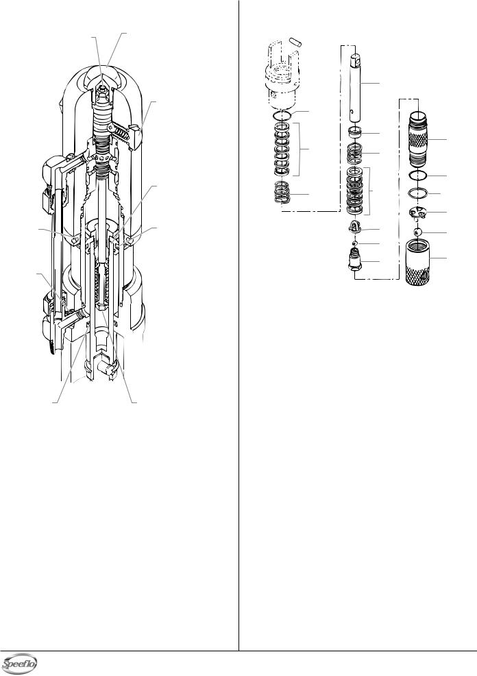
Hydraulic Motor Cut-Away
Torque flex locknut to
10ft./lbs. (146N/m). Use blue Loctite.
Use blue Loctite on lock ring.
Use hydraulic sealant.
Use 
 hydraulic
  sealant.
Seal lip must face up.
Torque head plug to 15 ft./lbs. (219 N/m). Do not over-tighten o-ring seal.
Torque trip retainers to
15 ft./lbs. (365 N/m). Do not over-tighten o-ring seal.
Torque piston retainers to
75 ft./lbs. (1095 N/m). Use red Loctite.
Seal lip must face down.
 Valve rod assembly is factory set and permanently Loctited. Do not disassemble.
Fluid Section
 1
1  2
2
|
|
|
Motor/ |
|
|
|
|
|
|
|
|
|
|
||
|
|
|
Pump |
6 |
|
|
|
|
|
|
Block |
|
|
|
|
|
3 |
|
|
|
|
||
|
|
|
|
|
7 |
12 |
|
|
|
|
|
|
|
|
|
|
4 |
|
8 |
|
|
||
|
|
|
|
|
|
|
|
|
|
|
|
|
|
13 |
|
|
5 |
4 |
|
3 |
|
||
|
|
|
|
|
|
14 |
|
|
|
|
|
|
9 |
15 |
|
|
|
|
|
|
|
|
|
|
|
|
|
|
10 |
|
|
|
|
|
|
|
11 |
16 |
|
|
|
|
|
|
|
|
|
Item |
Part # |
Description |
|
Quantity |
|||
1 |
143-019 |
|
Retaining ring ........................................... |
|
|
1 |
|
2 |
143-118 |
|
Connecting pin ......................................... |
|
|
1 |
|
3 |
145-031 |
|
O-ring, 37)(............................................ |
|
|
2 |
|
4 |
138-153 |
|
Packing set, leather/UHMPWPE/steel ..... |
2 |
|||
5 |
142-004 |
|
Packing spring, SS................................... |
|
1 |
||
6 |
144-117 |
|
Displacement rod, Severe Service 500....... |
1 |
|||
7 |
138-001 |
|
Spring retainer.......................................... |
|
|
1 |
|
8 |
142-003 |
|
Packing spring, SS................................... |
|
1 |
||
9 |
451-085 |
|
Upper ball cage ........................................ |
|
|
1 |
|
10 |
138-225 |
|
Ball, SS..................................................... |
|
|
1 |
|
11 |
143-945 |
|
Piston seat................................................ |
|
|
1 |
|
12 |
144-822 |
|
Pump cylinder, Severe Service 500 ......... |
1 |
|||
13 |
140-009 |
|
O-ring ....................................................... |
|
|
1 |
|
14 |
144-032 |
|
Lower ball cage, SS ................................. |
|
1 |
||
15 |
178-700 |
|
Ball, SS..................................................... |
|
|
1 |
|
16 |
144-013 |
|
Foot valve assembly ................................ |
|
1 |
||
Fluid Section Service Kit, Major (P/N 144-500) |
|
||||||
Item |
Part # |
Description |
|
Quantity |
|||
|
144-050 |
|
Pump Service Kit, Minor........................... |
|
1 |
||
6 |
144-117 |
|
Displacement rod ..................................... |
|
1 |
||
12 |
144-822 |
|
Pump cylinder........................................... |
|
|
1 |
|
Fluid Section Service Kit, Minor (P/N 144-050) |
|
||||||
Item |
Part # |
Description |
|
Quantity |
|||
1 |
143-019 |
|
Retainer ring............................................. |
|
|
1 |
|
3 |
145-031 |
|
O-ring, 37)(............................................ |
|
|
2 |
|
4 |
138-153 |
|
Packing set, leather/UHMWPE/steel........ |
2 |
|||
10 |
138-225 |
|
Ball, SS..................................................... |
|
|
1 |
|
13 |
140-009 |
|
O-ring ....................................................... |
|
|
1 |
|
15 |
178-700 |
|
Ball, SS..................................................... |
|
|
1 |
|
|
426-051 |
|
Loctite sealant .......................................... |
|
|
1 |
|
English |
24 |
© Titan Tool Inc. All rights reserved. |
|
|
|
|
|
|
 Loading...