

Page 1

Installation Instructions
for Stacked W
asher/Dryers
Original Instructions
Keep These Instructions for Futur
CAUTION: Read the instructions before using the machine.
(If this machine changes ownership, this manual must accompany machine.)
e Reference.
www.alliancelaundry.com
Part No. 805003R5
August 2017
Page 2

Page 3
WARNING
Risk of fire. Highly flammable material.
W881
IMPORTANT: The electrical installation in the site shall
comply with the Australian Electrical Standards,
AS3000, SAA wiring rules, and such local regulations
that might apply. In Australia and New Zealand, installation must comply with the Gas Installations Standard
AS/NZS 5601 Part 1: General Installations.
The maximum washing load (dry weight) shall not exceed 10 kg
[22 pounds].
The maximum drying load (dry weight) shall not exceed 9 kg [20
pounds].
Read all instructions before using unit.
WARNING
• Do not store or use gasoline or other flammable
vapors and liquids in the vicinity of this or any
other appliance.
• WHAT TO DO IF YOU SMELL GAS:
• Do not try to light any appliance.
• Do not touch any electrical switch; do not use
any phone in your building.
• Clear the room, building or area of all occu-
pants.
• Immediately call your gas supplier from a
neighbor’s phone. Follow the gas supplier’s instructions.
• If you cannot reach your gas supplier, call the
fire department.
• Installation and service must be performed by a
qualified installer, service agency or the gas supplier.
W052
WARNING
FOR YOUR SAFETY, the information in this manual
must be followed to minimize the risk of fire or explosion or to prevent property damage, personal injury or death.
W033
IMPORTANT: Purchaser must consult the local gas
supplier for suggested instructions to be followed if
the dryer user smells gas. The gas utility instructions
plus the SAFETY and WARNING note directly above
must be posted in a prominent location near the dryer
for customer use.
WARNING
• Installation of unit must be performed by a qualified installer.
• Install clothes dryer according to manufacturer’s
instructions and local codes.
• DO NOT install a clothes dryer with flexible plastic venting materials. If flexible metal (foil type)
duct is installed, it must be of a specific type
identified by the appliance manufacturer as suitable for use with clothes dryers. Refer to section
on connecting exhaust system. Flexible venting
materials are known to collapse, be easily crushed, and trap lint. These conditions will obstruct
clothes dryer airflow and increase the risk of fire.
©
Copyright, Alliance Laundry Systems LLC -
DO NOT COPY or TRANSMIT
W729R1
3 Part No. 805003R5
Page 4
WARNING
To reduce the risk of severe injury or death, follow all
installation instructions. Save these instructions.
W894
WARNING
FOR YOUR SAFETY
Do not store or use gasoline or other flammable vapors and liquids in the vicinity of this or any other
appliance.
W053
This product uses FreeRTOS V7.2.0 (www.freertos.org).
NOTE: For Australian models, the energy consumption
is measured as used once per week using the Perm
Press Automatic cycle with High Temperature and Dryness Dry at the rated load capacity of 7 kg.
©
Copyright, Alliance Laundry Systems LLC -
DO NOT COPY or TRANSMIT
4 Part No. 805003R5
Page 5

Table of Contents
Dimensions............................................................................................. 6
Installation............................................................................................. 9
Before You Start............................................................................................. 9
Tools..........................................................................................................9
Order of Installation Steps............................................................................9
Position Unit Near Installation Area................................................................. 9
Remove Shipping Materials.............................................................................9
Connect Fill Hoses........................................................................................10
Water Supply Requirements........................................................................11
Connecting Hoses......................................................................................11
Risers.......................................................................................................12
Connect Drain Hose to Drain Receptacle.........................................................12
Standpipe Installation................................................................................ 12
Wall Installation........................................................................................ 13
Laundry Tub Installation............................................................................13
Gas Dryers - Connect Gas Supply Pipe........................................................... 13
Connect Dryer Exhaust System...................................................................... 15
Exhaust Direction......................................................................................16
Exhaust System.........................................................................................16
Position and Level the Unit............................................................................17
Wipe Out Inside of Washer and Dryer Drums.................................................. 18
Plug In the Washer........................................................................................ 19
Electrical Requirements............................................................................. 19
Earth/Ground Instructions.......................................................................... 20
Plug In the Dryer.......................................................................................... 20
Electrical Requirements............................................................................. 20
Earth/Ground Instructions.......................................................................... 21
Check Installation......................................................................................... 22
Check Heat Source........................................................................................22
Electric Dryers.......................................................................................... 22
Gas Dryers................................................................................................22
Installer Checklist.................................................................................24
©
Copyright 2017, Alliance Laundry Systems LLC
All rights reserved. No part of the contents of this book may be reproduced or transmitted in any form or by any means without the expressed
written consent of the publisher.
©
Copyright, Alliance Laundry Systems LLC -
DO NOT COPY or TRANSMIT
5 Part No. 805003R5
Page 6
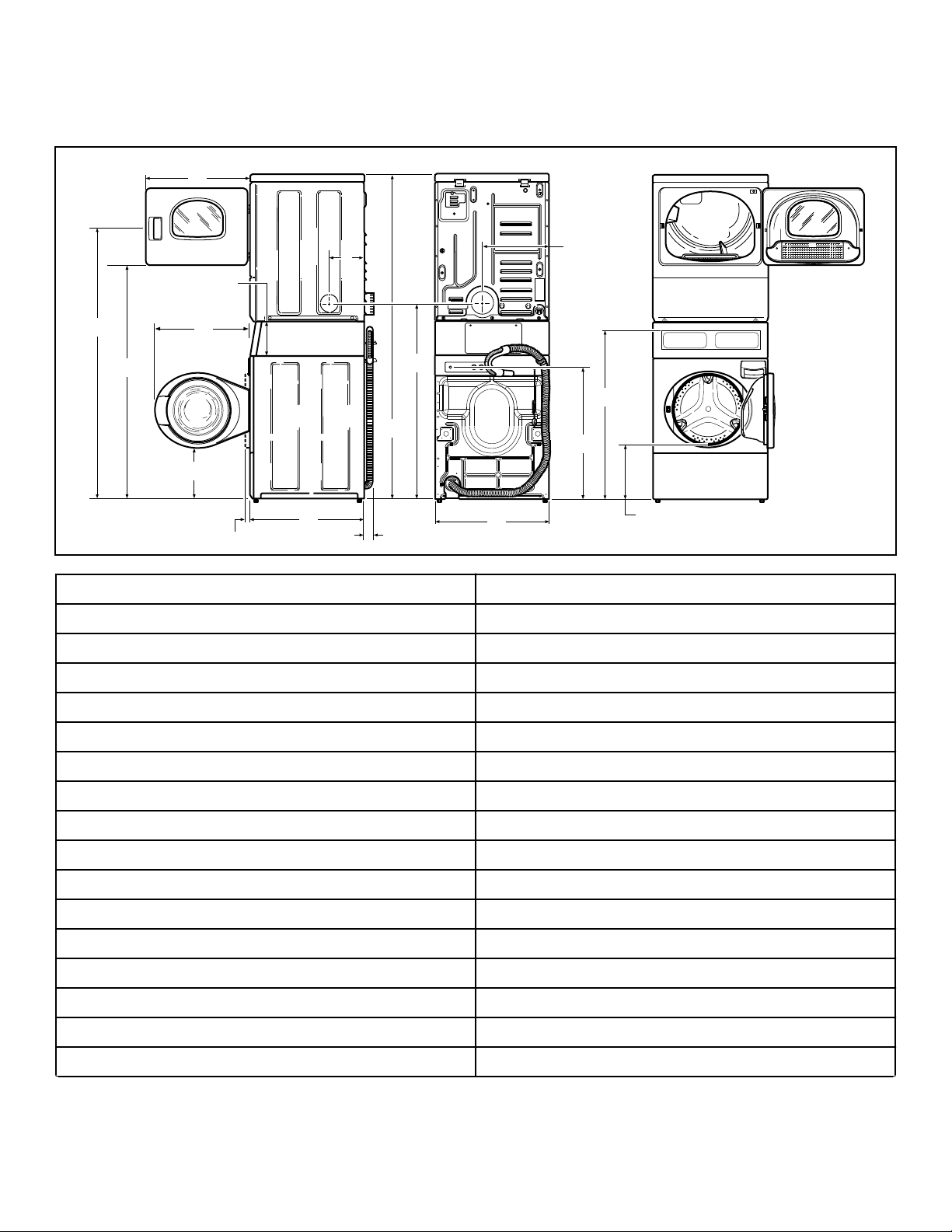
Electric Models
SWD1003N_SVG
O
Q
P
N
M
L
K
J
I
H
G
F
E
D
C
B
A
Dimensions
Dimensions
A * 1678 mm [66.06 in.]
B * 1447 mm [56.97 in.]
C 597 mm [23.5 in.]
D 213 mm [8.375 in.]
E 610 mm [24 in.]
F 203 mm [8 in.]
G 391 mm [15.4 in.]
H * 938 mm [36.9 in.]
I * 371 mm [14.6 in.]
J * 813 mm [32 in.]
K 683 mm [26.875 in.]
L * 1184 mm [46.62 in.]
M * 1986 mm [78.17 in.]
N 52 mm [2.04 in.]
O 704 mm [27.73 in.]
P (with door closed) 38 mm [1.5 in.]
Q * 333 mm [13.1 in.]
Table continues...
©
Copyright, Alliance Laundry Systems LLC -
DO NOT COPY or TRANSMIT
6 Part No. 805003R5
Page 7
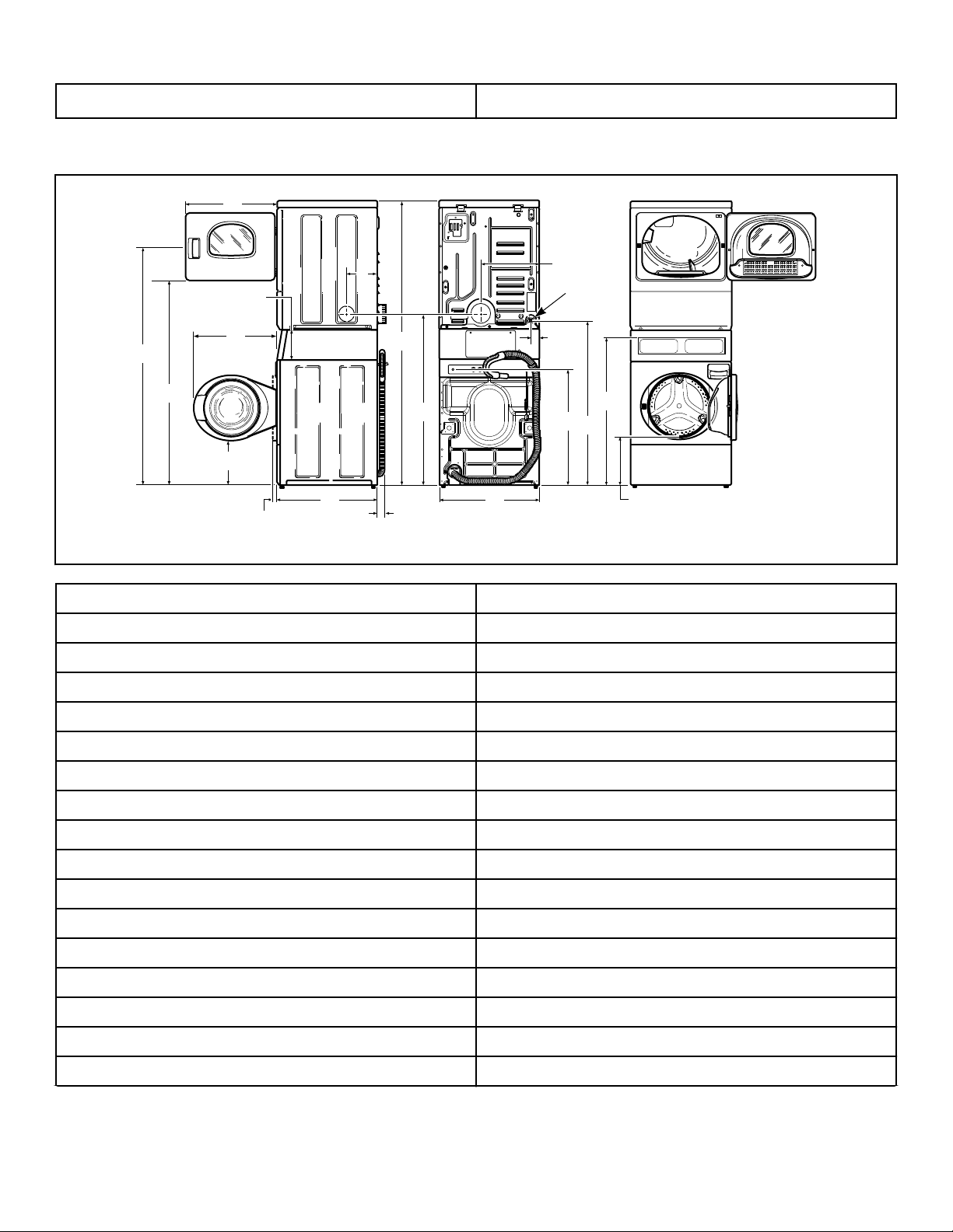
NOTE: Exhaust openings are 102 mm [4 inch] metal
SWD1004N_SVG
I
H
G
F
E
D
C
B
A
K
M
L
J
Q
R
O
S
P
N
1
ducting.
Gas Models
Dimensions
* With leveling legs turned into base.
1. 3/8 in. NPT Gas Connection
A *1678 mm [66.06 in.]
B *1447 mm [56.97 in.]
C 597 mm [23.5 in.]
D 213 mm [8.375 in.]
E 610 mm [24 in.]
F 203 mm [8 in.]
G 391 mm [15.4 in.]
H 59 mm [2.3 in.]
I *938 mm [36.9 in.]
J *371 mm [14.6 in.]
K *1140 mm [44.87 in.]
L *813 mm [32 in.]
M 683 mm [26.875 in.]
N *1184 mm [46.62 in.]
O *1986 mm [78.17 in.]
P 52 mm [2.04 in.]
Q 704 mm [27.73 in.]
©
Copyright, Alliance Laundry Systems LLC -
DO NOT COPY or TRANSMIT
7 Part No. 805003R5
Table continues...
Page 8

Dimensions
R (with door closed) 38 mm [1.5 in.]
S *333 mm [13.1 in.]
* With leveling legs turned into base.
NOTE: Exhaust openings are 102 mm [4 inch] metal
ducting.
©
Copyright, Alliance Laundry Systems LLC -
DO NOT COPY or TRANSMIT
8 Part No. 805003R5
Page 9

Installation
SWD1021N_SVG
11
10
9
8
4
3
2
1
6
7
5
Installation
Before You Start
Tools
For most installations, the basic tools you will need are:
1. Wrench
2. 1/4 inch Driver
3. Screwdriver
4. Level
5. Wood Block
6. Pliers
7. 5/16 Inch Socket Wrench
8. Gloves
9. Teflon Tape (Gas Models)
10. Duct Tape
11. Safety Glasses
Figure 1
WARNING
Any disassembly requiring the use of tools must be
performed by a suitably qualified service person.
W299
Order of Installation Steps
The proper order of steps must be followed to ensure correct installation. Refer to the list below when installing your unit.
1. Position unit near area of installation.
2. Remove the shipping materials.
3. Connect the fill hoses.
4. Connect the drain hose to the drain receptacle.
5. For gas models only, connect the gas supply pipe. Check for
gas leaks.
6. Connect dryer to exhaust system.
7. Position and level the unit.
8. Wipe out inside of washer and dryer drums.
9. Plug in the washer and dryer.
10. Check installation.
11. Start and run the dryer in a heat setting to verify dryer is heating.
Position Unit Near Installation Area
Move unit so that it is within 1.2 meters [4 feet] of the desired
area of installation.
CAUTION
Washer and dryer are not designed to be operated as
separated, side-by-side units.
NOTE: If the unit is delivered on a cold day (below
freezing), or is stored in an unheated room or area during the cold months, do not attempt to operate it until
the unit has had a chance to warm up.
NOTE: Some moisture in the wash drum is normal. Water is used during testing at the manufacturer.
NOTE: This appliance is suitable for use in countries
having a warm, damp climate.
©
Copyright, Alliance Laundry Systems LLC -
DO NOT COPY or TRANSMIT
W187
NOTE: For best performance and to minimize vibration
or movement, install washer on a solid, sturdy and level floor. Some floors may need to be reinforced, especially on a second floor or over a basement. Do not install the washer on carpeting, soft tile or other weakly
supported structures.
Remove Shipping Materials
1. Remove two screws at bottom of front access panel. Rotate
bottom of panel out and remove panel.
9 Part No. 805003R5
Page 10

FLW2378N_SVG
FLW2296N_SVG1
FLW2297N_SVG1
FLW2358N_SVG
Installation
Figure 2
2. Remove two 9/16 inch bolts and washers holding shipping
brace to weight.
3. Remove two 9/16 inch bolts and washers holding shipping
brace to washer base and remove brace.
Figure 4
6. Insert two plugs included in accessories bag into rear shipping
bolt holes.
Figure 3
4. Go to rear of washer and pull label from rear shipping bolts.
5. Remove two 9/16 inch bolts. Unscrew each bolt while applying forward pressure just until bolt stops unthreading. Work
each bolt and spacer out by hand using a circular motion.
NOTE: Avoid backing bolts out completely or
spacers might fall into cabinet.
Figure 5
7. Replace front access panel.
8. Save all shipping materials. They must be reinstalled any time
washer is moved more than four feet.
IMPORTANT: Do not lift or transport unit from front
or without shipping materials installed. Refer to the
User’s Guide for proper instructions on reinstalling
the shipping materials.
Connect Fill Hoses
WARNING
Under certain conditions, hydrogen gas may be produced in a hot water system that has not been used
for two weeks or more. HYDROGEN GAS IS EXPLOSIVE. If the hot water system has not been used for
such a period and before using the washer, turn on
all hot water taps and let the water flow from each for
several minutes. This will release any accumulated
hydrogen gas. The gas is flammable. Do not smoke
or use an open flame during this time.
©
Copyright, Alliance Laundry Systems LLC -
DO NOT COPY or TRANSMIT
W029
10 Part No. 805003R5
Page 11

Water Supply Requirements
Water supply taps must fit standard 19 mm [3/4 inch] female garden hose couplings. DO NOT USE SLIP-ON OR CLAMP-ON
CONNECTIONS.
NOTE: Water supply taps should be readily accessible
to permit turning them off when washer is not being
used.
Recommended cold water temperature is 10° to 24° Celsius [50°
to 75° Fahrenheit]. Recommended maximum hot water temperature is 51° Celsius [125° Fahrenheit]. Warm water is a mixture of
hot and cold water. Warm water temperature is dependent upon
the water temperature and the pressure of both the hot and cold
water supply lines.
WARNING
To prevent personal injury, avoid contact with inlet
water temperatures higher than 51° Celsius [125°
Fahrenheit] and hot surfaces.
W748
Maximum flow rate for all water temperatures is 9.46 liters per
minute [2.5 gallons per minute] ± 15%.
Water pressure must be a minimum of 138 to a maximum of 827
kPa [minimum of 20 to a maximum of 120 pounds per square
inch] static pressure measured at the tap.
NOTE: Water pressure under 138 kPa [20 pounds per
square inch] will cause an extended fill time in the
washer and may not properly flush out the detergent
dispenser.
The appliance is to be connected to the water mains using new
hose-sets and the old hose-sets should not be reused.
Turn on the water supply taps and flush the lines for approximately two minutes to remove any foreign materials that could
clog the screens in the water mixing valve. This is especially important when installing your washer in a newly constructed or
renovated building. Build-up may have occurred during construction.
Connecting Hoses
To comply with Australian water regulations and Australian
standard AS/NZS3500.1, an approved dual check valve backflow
prevention device with the watermark must be fitted at the point
of connection(s) between the supply and the fitting. Refer to Fig-
ure 7 .
Installation
Figure 6
Connections should be supplied by a hot and a cold water line per
national and local codes and in accordance with AS/NZS 3500.1.
1. Insert rubber washers and filter screens (from accessories
bag) in water fill hose couplings (two hoses supplied with
washer). The filter screen must be facing outward.
NOTE:
If using black rubber hoses with black and brass couplings: Insert filter screens into the BLACK colored
hose couplings (BSPP thread). Insert rubber washers
into the brass colored hose couplings (Garden Hose
Thread [GHT]).
If using gray braided hoses with silver hose couplings
(one with hex nut): Insert filter screens into the hex nut
shaped hose couplings (BSPP thread). Insert rubber
washers into the knurled, round shaped hose couplings (GHT).
2. Connect fill hose couplings with filter screens to water supply
taps.
3. Connect the other hose couplings to the hot and cold valve
connections at the rear of the washer.
NOTE:
If using black rubber hoses with black and brass couplings: Connect the BLACK colored hose coupling
(BSPP thread) end of the fill hoses (with filter screens)
to the water supply taps. Then connect end of hoses
with the brass colored hose couplings (GHT) to the hot
and cold water mixing valve connections at rear of
washer.
If using gray braided hoses with silver hose couplings
(one with hex nut): Connect the hex nut shaped hose
couplings (BSPP thread, with filter screens) to the water supply taps. Then connect couplings with knurled,
round shaped couplings (GHT) to the hot and cold water mixing valve connections at rear of washer.
4. Make sure the hose from the hot water tap goes to the water
mixing valve marked “H” and the hose from the cold tap goes
to the valve marked “C”.
5. Thread hose couplings onto valve connections finger tight.
Then turn 1/4 turn with pliers.
IMPORTANT: DO NOT cross thread or overtighten
couplings. This will cause them to leak.
©
Copyright, Alliance Laundry Systems LLC -
DO NOT COPY or TRANSMIT
11 Part No. 805003R5
Page 12

FLW2446N_SVG
HOT
COLD
9
8
7
4
3
2
1
5
6
W005I_SVG
2
1
Installation
6. Turn water on and check for leaks.
7. If leaks are found, retighten the hose couplings.
8. Continue tightening and rechecking until no leaks are found.
1.
1. Tap
2. Fill Hoses
3. Install this end of hose to valve connections at rear of
washer
4. Plain Rubber Washer
5. Cold Water Connection
6. Hot Water Connection
7. Install this end of hose to water supply tap (Black colored
or hex nut shaped coupling for BSPP thread)
8. Filter Screens
9. Dual Check Valves
Risers (Air cushions)
2. Water Supply Taps
Figure 8
Connect Drain Hose to Drain
Receptacle
Remove the drain hose from its shipping position on the rear of
the washer by unhooking the hose from the retainer clamp and by
removing the shipping tape.
Install the drain hose into the drain receptacle (standpipe, wall or
laundry tub) following the instructions below.
Figure 7
IMPORTANT:
Hoses and other rubber parts deteriorate after exten-
IMPORTANT: Drain receptacle must be capable of handling a minimum of 32 mm [1-1/4 inch] outside diameter drain hose.
ded use. Hoses may develop cracks, blisters or material wear from the temperature and constant high pres-
Drain Flow Rate
sure they are subjected to.
Flow Rate
liters per minute [gallons per minute]
All hoses should be checked on a monthly basis for
any visible signs of deterioration. Any hose showing
the signs of deterioration listed above should be replaced immediately. All hoses should be replaced every five years.
IMPORTANT: Turn off water supply taps after check-out
and demonstration. Owner should turn off water supply
whenever there will be an extended period of non-use.
Risers
Risers (or air cushions) may have to be installed if the pipes
knock or pound when flow of water stops. The risers are more efficient when installed as close as possible to the water supply
taps. Refer to Figure 8 .
Drain Height
0.9 m [3 ft.] 27.7 [7.3]
1.5 m [5 ft.] 17.8 [4.7]
1.8 m [6 ft.] 13.4 [3.5]
2.1 m [7 ft.] 4.8 [1.3]
2.4 m [8 ft.] 0 [0]
Standpipe Installation
1. Place the drain hose into the standpipe.
2. Remove the beaded tie-down strap from accessories bag and
place around standpipe and drain hose. Refer to Figure 9 .
©
Copyright, Alliance Laundry Systems LLC -
DO NOT COPY or TRANSMIT
12 Part No. 805003R5
Page 13

a. Insert the end of the beaded strap into the larger hole
SWD1010N_SVG
3
2
1
H023i_SVG
1
3
2
SWD1011N_SVG
2
1
found on the end of the strap.
b. Tighten to desired fit.
c. Lock strap in place by pulling beaded strap into the tam-
pered smaller opening of the beaded strap end. A distinct
snap noise should be heard once the strap is properly seat-
ed.
d. Pull on the strap once locked in place to ensure beaded
strap is properly installed. This will prevent the drain hose
from dislodging from drain receptacle during use.
Drain Hose
1.
2. Beaded Strap (tape if necessary)
3. Fill Hoses
Figure 10
Laundry Tub Installation
Installation
1. 610 to 914 mm [24 to 36 in.] Recommended Height
2. Beaded strap from accessory bag
3. Standpipe 51 mm [2 in.] or 40 mm [1-1/2 in.]
Figure 9
Wall Installation
For installations of this type, the drain hose MUST be secured to
one of the fill hoses using the beaded strap from accessories bag.
Refer to Figure 10 .
NOTE: End of drain hose must not be below 610 mm
[24 in.].
For this type of installation, the drain hose MUST be secured to
the stationary tub to prevent hose from disloding during use. Refer to Figure 11 . Use the beaded strap (supplied in accessories
bag) to secure hose.
1. Drain Hose
2. Beaded Strap (tape if necessary)
Figure 11
©
Copyright, Alliance Laundry Systems LLC -
DO NOT COPY or TRANSMIT
13 Part No. 805003R5
Page 14

D246I_SVG
1
4
2
3
Installation
Gas Dryers - Connect Gas Supply Pipe
NOTE: The gas service to a gas dryer must conform
with the local codes and ordinances and in Australia
and New Zealand, installation must comply with the
Gas Installations Standard AS/ NZS 5601 Part 1: General Installations. In the absence of local codes and ordinances, applicable National codes should be followed.
1. Install the dryer with sufficient clearance for adequate air circulation, and for the ease of the dryer installation, servicing
and operation. For maximum drying performance, we recommend you allow more clearance than the clearances that are
listed throughout this manual.
2. Remove the shipping cap from the gas connection at the rear
of the dryer. Make sure you do not damage the pipe threads
when removing the cap.
NOTE: If gas supply connection is British Standard
Pipe Tapered thread (BSPT), order 44178804 brass
female NPT (FPT) to male BSPT gas pipe thread
adapter, available at extra cost.
3. Make certain your dryer is equipped for use with the type of
gas in your laundry room.
NOTE: Natural gas, 37.3 MJ/m3 [1000 Btu/ft3], service must be supplied at 1.13 kPa [4.54 inch]water
column pressure. Do not connect the dryer to L.P.
(Liquefied Petroleum) gas service without converting the gas valve. A No. 401P3 L.P. Gas Conversion
Kit must be installed by the Manufacturer’s Authorized Dealers, Distributors, or local service personnel.
WARNING
To reduce the risk of gas leaks, fire or explosion:
• The dryer must be connected to the type of
gas as shown on nameplate located in the
door recess.
• Use a new flexible stainless steel connector.
• Use pipe joint compound insoluble in L.P. (Liquefied Petroleum) Gas, or Teflon tape, on all
pipe threads.
• Purge air and sediment from gas supply line
before connecting it to the dryer. Before tightening the connection, purge remaining air from
gas line to dryer until odor of gas is detected.
This step is required to prevent gas valve contamination.
• Do not use an open flame to check for gas
leaks. Use a non-corrosive leak detection fluid.
• Any disassembly requiring the use of tools
must be performed by a suitably qualified service person.
W316
NOTE: L.P. gas, 93.1 MJ/m3 [2500 Btu/ft3], service
must be supplied at 2.75 kPa [11.04 inch] water column pressure and a vent to the outdoors must be
provided.
4. If local codes allow the use of flexible gas tubing, connect the
9.5 mm [3/8 inch] NPT (National Pipe Thread) gas connection at the rear of the dryer to the laundry room’s gas line with
new flexible stainless steel tubing (using design certified Australian Gas Association connector only).
IMPORTANT: Use local codes of practice for gas installation.
This dryer is equipped with jet for Natural gas.
Gas Consumption
Gas Supply Pressure
Natural 21.9 MJ
L.P. 21.9 MJ
Natural 1.13 kPa
L.P. 2.75 kPa
1. New Stainless Steel Flexible Connector – Use Only If Allowed By Local Codes (Use design AGA certified connector)
2. Pressure Test Point
3. External Shut-Off Valve
4. 3/8 in. NPT Gas Connection
Figure 12
NOTE: When connecting gas supply line, a pressure
test point must be installed downstream from the
shutoff valve for checking inlet gas pressure.
©
Copyright, Alliance Laundry Systems LLC -
DO NOT COPY or TRANSMIT
14 Part No. 805003R5
Page 15

Installation
5. The gas line to your laundry room should be made of black
iron pipe. A 9.5 mm [3/8 inch] pipe with an inside diameter of
11.7 mm [0.46 inch] will be adequate if length of supply line
is not over 6 m [20 feet]. If length exceeds this, use 12.7 mm
[1/2 inch] pipe. If copper semi-rigid tubing is used it must be
internally tinned or equivalently treated to resist sulfur corrosion.
NOTE: The dryer and its individual gas valve must
be disconnected from the gas supply piping system
during any pressure testing of that system at test
pressures in excess of 3.45 kPa [1/2 psig].
6. Check all pipe connections (internal and external) for gas
leaks with a soapy solution. Gas connections should be
checked annually for leakage.
7. The dryer gas valve is equipped with a pressure test point for
checking manifold pressure.
For proper operation at altitudes above 760 m [2500 feet] the gas
valve spud orifice size must be reduced to ensure complete combustion. Refer to Table 1 and Table 2 .
Natural Gas Altitude Adjustments
Altitude Orifice Size
mm [in-
ches]
Part Num-
berm [ft] No.
Connect Dryer Exhaust System
WARNING
To reduce the risk of fire and combustion gas accumulation the dryer MUST be exhausted to the outdoors.
W604
WARNING
To reduce the risk of fire and the accumulation of
combustion gases, DO NOT exhaust dryer air into a
window well, gas vent, chimney or enclosed, unventilated area, such as an attic, wall, ceiling, crawl
space under a building or concealed space of a
building.
W045
WARNING
To reduce the risk of fire, DO NOT use plastic or thin
foil ducting to exhaust the dryer.
W354
760 [2500] 45 2.08 [0.0820] D503779
1370 [4500] 46 2.06 [0.0810] D503780
1830 [6000] 47 1.99 [0.0785] D503781
2290 [7500] 48 1.93 [0.0760] D503782
2900 [9500] 49 1.85 [0.0730] D503783
3355 [11000] 50 1.78 [0.0700] D503784
Table 1
L.P. Altitude Adjustments
Altitude Orifice Size
mm [in-
ches]
1370 [4500] 56 1.2 [0.0465] D503786
3000 [9500] 57 1.1 [0.0430] 60941
Table 2
Part Num-
berm [ft] No.
WARNING
To reduce the risk of fire, the exhaust duct and
weather hood MUST be fabricated of a material that
will not support combustion. Rigid or flexible metal
pipe is recommended for a clothes dryer.
W048
©
Copyright, Alliance Laundry Systems LLC -
DO NOT COPY or TRANSMIT
15 Part No. 805003R5
Page 16

SWD997N_SVG
21
Installation
1. Correct
2. Incorrect
• Static pressure in exhaust duct should not be greater than 10
mm water column [0.4 inches water column], measured with
manometer placed on exhaust duct 610 mm [two feet] from
dryer (check with dryer running and no load).
• Exhausting dryer in hard-to-reach locations can be done by
installing 521P3 Flexible Metal Vent Kit (available as optional equipment at extra cost).
• Sufficient make-up air must be supplied to replace the air exhausted by the dryer. The free area of any opening for outside
air must be at least 25806 mm2 [40 in.2] per unit.
• Failure to exhaust dryer properly will void warranty.
• A dryer will dissipate 681,392 J/m2 [60 Btu/ft2] of surface
area exposed to the conditioned air.
NOTE: Venting materials are not supplied with the dryer (obtain locally).
IMPORTANT: DO NOT block the airflow at the bottom of
the dryer’s front panel with laundry, rugs, etc. Blockage
will decrease airflow through the dryer, thus reducing
the efficiency of the dryer.
Exhaust Direction
Figure 13
• DO NOT use plastic, thin foil or type B ducting. Rigid metal
duct is recommended.
• Locate dryer so exhaust duct is as short as possible.
• Be certain old exhaust ducts are cleaned before installing your
new dryer.
• Use 102 mm [4 inch] diameter rigid or flexible metal duct.
• The male end of each section of duct must point away from
the dryer.
• Use as few elbows as possible.
• Use of duct tape or pop-rivets on all seams and joints is recommended, if allowed by local codes. DO NOT use sheet
metal screws or fasteners on exhaust pipe joints which extend
into the duct and catch lint.
• Ductwork that runs through unheated areas must be insulated
to help reduce condensation and lint build-up on pipe walls.
• In mobile home installations, dryer exhaust duct must be secured to mobile home structure.
• Dryer exhaust duct MUST NOT terminate under mobile
home.
• Exhaust duct must not be connected to any other duct, vent, or
chimney.
• Dryer exhausts 5.09 cmm (180 cfm) per unit (measured at
back of dryer).
• DO NOT install flexible duct in concealed spaces, such as a
wall or ceiling.
The dryer can be exhausted to the outdoors through the back, left,
right or bottom of the dryer. EXCEPTION: Gas dryers cannot be
vented out the left side because of the burner housing.
Dryer is shipped from factory ready for rear exhaust.
Exhausting the dryer through sides or bottom can be accomplished by installing a Directional Exhaust Kit, 528P3, available as
optional equipment at extra cost.
IMPORTANT: DO NOT block the airflow at the bottom of
the dryer’s front panel with laundry, rugs, etc. Blockage
will decrease airflow through the dryer, thus reducing
the efficiency of the dryer.
Exhaust System
For best drying results, recommended maximum length of exhaust system is shown in Table 3 .
To prevent backdraft when dryer is not in operation, outer end of
exhaust pipe must have a weather hood with hinged dampers (obtain locally).
NOTE: Weather hood should be installed at least 305
mm [12 inches] above the ground. Larger clearances
may be necessary for installations where heavy snowfall can occur.
©
Copyright, Alliance Laundry Systems LLC -
DO NOT COPY or TRANSMIT
16 Part No. 805003R5
Page 17

Weather Hood Type
D673I_SVG
1
1
D802I_SVG
1
Installation
Number of 90° Elbows
Recommended Use Only for Short Run Installations
1. 102 mm [4 in.]
1. 64 mm [2.5 in.]
Maximum length of 102 mm [4 in.] diameter rigid metal duct.
0 19.8 m [65 feet] 16.8 m [55 feet]
1 16.8 m [55 feet] 14.3 m [47 feet]
2 14.3 m [47 feet] 12.5 m [41 feet]
3 11.0 m [36 feet] 9.1 m [30 feet]
4 8.5 m [28 feet] 6.7 m [22 feet]
Table 3
NOTE: Deduct 1.8 m [6 feet] for each additional elbow.
NOTE: The maximum length of a 102 mm [4 in.] diameter flexible metal duct must not exceed 2.4 m [7.87 ft.],
as required to meet UL2158, clause 7.3.2.A.
Position and Level the Unit
WARNING
Units elevated above floor level must be anchored to
that elevated surface, base or platform. The material
used to elevate the unit should also be anchored to
the floor to ensure that the unit will not walk or that
the unit can not be physically pulled, tipped or slid
from its installed position. Failure to do so may result in conditions which can produce serious injury,
death and/or property damage.
W307
1. Position unit so it has sufficient clearance for installation and
servicing.
©
Copyright, Alliance Laundry Systems LLC -
DO NOT COPY or TRANSMIT
17 Part No. 805003R5
Page 18

SWD1006N_SVG
C
E
E
A B
D
SWD1029N_SVG
4
5
3
2
6
1
Installation
NOTE: Shaded areas indicate adjacent structure.
6. Loosen 7/8 in. locknut and adjust legs by screwing into or out
of unit base until the unit is level from side to side and front
to back (using a level). Unit should not rock.
NOTE: Leveling legs can also be adjusted from inside the unit using an adjustable wrench.
7. Tighten the locknuts securely against the unit base. If the
locknuts are not tight, unit will move out of position during
operation.
NOTE: DO NOT slide unit across floor if the leveling
legs have been extended. Legs and base could become damaged.
8. Remove rubber feet from accessories bag and place on all
four leveling legs.
9. Verify that unit doesn’t rock.
Dryer and Exhaust Duct Clearances
Area Description
A Left Dryer Side 0 mm [0 in.]
B Right Dryer Side 25 mm [1 in.]
C Dryer Top 152 mm [6 in.]
D * Dryer Rear 102 mm [4 in.]
E Exhaust Duct
* Rear clearance is minimum. 152 mm [6 inches] are
recommended when venting through rear of unit.
NOTE: Use of the dispenser drawer or unit doors as
a handle in the transportation of the unit may cause
damage to the dispenser or doors.
2. Place unit in position on a solid, sturdy and level floor. Installing the unit on any type of carpeting, soft tile or other weakly
supported structures is not recommended.
3. The unit must not be installed behind a lockable door, a sliding door, or a door with a hinge on the opposite side of the
unit.
4. Place a level on the raised portion of cabinet top and check if
the unit is level from side to side and front to back.
5. If unit is not level, tilt unit to access the front and rear leveling legs. For easier access to leveling legs, prop up unit with a
wooden block.
©
Copyright, Alliance Laundry Systems LLC -
DO NOT COPY or TRANSMIT
Minimum
Clearance
51 mm [2 in.]
Clearance to
Combustible Materials
1. Level
2. Wood Block
3. Rubber Foot
4. Leveling Leg
5. Locknut
6. Unit Base
Wipe Out Inside of Washer and Dryer
Figure 14
Drums
IMPORTANT: Prior to first wash, use an all-purpose
cleaner, or a detergent and water solution, and a damp
cloth to remove shipping dust from inside the drums.
18 Part No. 805003R5
Page 19

SWD1012N_SVG
SWD1013N_SVG
Installation
WARNING
To reduce the risk of fire, electric shock, serious injury or death, all wiring and earth/ground connections MUST conform with the latest edition of the
AS/NZS 2040.2:2005 and such local regulations as
might apply. It is the customer’s responsibility to
have the wiring, fuses and circuit breakers installed
by a qualified electrician to make sure adequate electrical power is available to the washer.
When plugging in the washer:
W895
Figure 15
Figure 16
Plug In the Washer
Electrical Requirements
240 Volt/50 Hertz with 3-Prong Earth/Ground Plug
This appliance is to be supplied through a residual current device
(RCD) having a rated residual operating current not exceeding 30
mA.
NOTE: The wiring diagram is located in the control cabinet.
• DO NOT overload circuits.
• DO NOT use an extension cord.
• DO NOT use an adapter.
• DO NOT operate both a washer and a gas dryer on the same
circuit.
CAUTION
If this appliance is supplied from a cord extension
set or an electrical portable outlet device, the cord
extension set or electrical portable outlet device
must be positioned so that it is not subject to
splashing or ingress of moisture.
W563
WARNING
To reduce the risk of an electric shock or fire, DO
NOT use an extension cord or an adapter to connect
the washer to the electric power source.
W082
The washer is designed to be operated on a separate polarized
three-wire, earth/ground, 240 Volt, 50 Hertz, single-phase electrical circuit protected by a 10 ampere fuse, equivalent fusetron or
circuit breaker.
The 3-prong earth/ground plug on the power cord should be plugged directly into a polarized three-slot receptacle properly installed and connected to a protective earth/ground and rated 240
Volts AC (alternating current) 10 Amps. Refer to Figure 17 to determine correct polarity of the wall receptacle.
©
Copyright, Alliance Laundry Systems LLC -
DO NOT COPY or TRANSMIT
19 Part No. 805003R5
Page 20

TLW2166N_SVG
2
1
43
3
Installation
Standard 240 Volt, 50 Hertz, 3 Wire Effective Earth/
Ground Circuit
1. Power Cord
2. Earth/Ground Prong
3. 240 Volt/50 Hertz
4. 0 Volt
cian or your local electrical utility company check it and correct any problems.
• Do not operate other appliances on the same circuit when this
appliance is operating.
WARNING
This unit is equipped with a three-prong (earth/
ground) plug for your protection against shock hazard and should be plugged directly into a protective
earth/ ground three-prong receptacle. Do not cut or
remove the earth/ground prong from this plug.
W823
If the supply cord is damaged, it must be replaced by the manufacturer, its service agent, or similarly qualified persons in order
to avoid a hazard.
Plug In the Dryer
This appliance is to be supplied through a residual current device
(RCD) having a rated residual operating current not exceeding 30
mA.
Electrical Requirements
Figure 17
Earth/Ground Instructions
This appliance must be properly connected to protective earth/
ground. In the event of malfunction or breakdown, the earth/
ground will reduce the risk of electric shock by providing a path
of least resistance for electric current.
The appliance is equipped with a cord having an equipment earth/
ground conductor and a three-prong earth/ground plug. The plug
must be plugged into an appropriate outlet that is properly installed and connected to a protective earth/ground in accordance with
all local codes and ordinances.
WARNING
Improper connection of the equipment earth/ground
conductor can result in a risk of electric shock.
Check with a qualified electrician or service person if
you are in doubt as to whether the unit is properly
connected to a protective earth/ground.
• DO NOT modify the plug provided with the unit – if it will
not fit the outlet, have a proper outlet installed by a qualified
electrician.
• If the laundry room’s electrical supply does not meet the
above specifications and/or if you are not sure the laundry
room has an effective earth/ground, have a qualified electri-
W893
Electric Dryer
NOTE: The wiring diagram is located in the control cabinet.
WARNING
To reduce the risk of fire, electric shock or personal
injury, all wiring and earthing to the dryer MUST conform with the latest edition of the Australian Electrical Standards, AS3000, SAA wiring rules, and such
local regulations that might apply.
W478
This dryer is designed to be operated on a two-wire, plus earth/
ground, 240 Volt, 50 Hertz, single-phase circuit, fused at 20 Amperes.
Insert the dryer’s lead-in cord plug into an earthing three-slotplus earth/ground, wall receptacle on a separate circuit. Do not
operate other appliances on the same circuit.
©
Copyright, Alliance Laundry Systems LLC -
DO NOT COPY or TRANSMIT
20 Part No. 805003R5
Page 21

CAUTION
DRY2587N_SVG
20
A
250 V
1
3
4
2
DRY2612N_SVG
10A
250
V
1
3
4
2
If this appliance is supplied from a cord extension
set or an electrical portable outlet device, the cord
extension set or electrical portable outlet device
must be positioned so that it is not subject to
splashing or ingress of moisture.
W563
Installation
This dryer is designed to be operated on a two-wire, plus earth/
ground, 240 Volt, 50 Hertz, single-phase circuit, fused at 10 Amperes.
Insert the dryer’s lead-in cord plug into an earthing three-slotplus earth/ground, wall receptacle on a separate circuit. Do not
operate other appliances on the same circuit.
CAUTION
If the supply cord is damaged, it must be replaced by the manufacturer, its special agent or similarly qualified persons in order to
avoid a hazard.
1. Lead-In Cord
2. Earth/Ground Screw
3. Lead-In Cord Plug
4. Earth/Ground
If this appliance is supplied from a cord extension
set or an electrical portable outlet device, the cord
extension set or electrical portable outlet device
must be positioned so that it is not subject to
splashing or ingress of moisture.
W563
IMPORTANT: Remove all objects from pockets such as
lighters and matches.
If the supply cord is damaged, it must be replaced by the manufacturer, its special agent or similarly qualified persons in order to
avoid a hazard.
Figure 18
Gas Dryer
NOTE: The wiring diagram is located in the control cabinet.
1. Lead-In Cord
2. Earth/Ground Screw
3. Lead-In Cord Plug
WARNING
To reduce the risk of fire, electric shock or personal
injury, all wiring and earthing to the dryer MUST conform with the latest edition of the Australian Electri-
4. Earth/Ground
Figure 19
Earth/Ground Instructions
cal Standards, AS3000, SAA wiring rules, and such
local regulations that might apply.
W478
This appliance must be properly connected to protective earth/
ground. In the event of malfunction or breakdown, the earth/
ground will reduce the risk of electric shock by providing a path
of least resistance for electric current.
©
Copyright, Alliance Laundry Systems LLC -
DO NOT COPY or TRANSMIT
21 Part No. 805003R5
Page 22

Installation
The dryer is equipped with a cord having an equipment-earth/
ground conductor and a 3 prong earth/ground plug. The plug
must be plugged into an appropriate outlet that is properly installed and connected to a protective earth/ground in accordance with
all local codes and ordinances.
Do not modify the plug provided with the dryer – if it will not fit
the outlet, have a proper outlet installed by a qualified electrician.
WARNING
Improper connection of the equipment earth/ground
conductor can result in a risk of electric shock.
Check with a qualified electrician or service person if
you are in doubt as to whether the dryer is properly
connected to a protective earth/ground.
W886
If the electrical supply does not meet the above specifications
and/or you are not sure your building has an effective earth/
ground, have a qualified electrician or your local electrical utility
company check it and correct any problems.
Check Installation
1. Refer to Installer Checklist on the back cover of this manual
and make sure that unit is installed correctly.
2. Run washer with a test load to make sure it is operating properly and properly leveled.
a. Put about six pounds of laundry (four bath towels and
three jeans) into washer.
b. Close door.
c. Select Spin cycle and press Start.
d. When washer spins at high speed, verify that it is stable.
e. If it is not, after cycle is complete, refer to Position and
Level the Washer to readjust leveling legs.
Check Heat Source
Electric Dryers
1. Close the loading door and start the dryer in a heat setting (refer to the operation instructions).
2. After the dryer has operated for three minutes, the exhaust air
or exhaust pipe should be warm.
Gas Dryers
IMPORTANT: This operation is to be conducted by
qualified personnel only.
1. To view the burner flame, remove the lower front panel of the
dryer.
2. Close the loading door and start the dryer in a heat setting (refer to the operation instructions). The dryer will start, the igniter will glow red and the main burner will ignite.
IMPORTANT: If all air is not purged out of gas line,
gas igniter may go off before gas is ignited. If this
happens, after approximately two minutes igniter
will again attempt gas ignition.
IMPORTANT: If igniter does not light, make sure gas
is turned on.
3. After the dryer has operated for approximately five minutes,
observe burner flame through lower front panel.
4. Adjust the air shutter to obtain a soft, uniform blue flame. (A
lazy, yellow-tipped flame indicates lack of air. A harsh, roaring, very blue flame indicates too much air.) Adjust the air
shutter as follows:
a. Loosen the air shutter lockscrew.
b. Turn the air shutter to the left to get a luminous yellow-
tipped flame, then turn it back slowly to the right to obtain
a steady, soft blue flame.
c. After the air shutter is adjusted for proper flame, tighten
the air shutter lockscrew securely.
5. Reinstall the lower front panel.
WARNING
To reduce the risk of serious injury or death, lower front panel must be in place during normal operation.
W158
6. After the dryer has operated for approximately three minutes,
exhaust air or exhaust pipe should be warm.
©
Copyright, Alliance Laundry Systems LLC -
DO NOT COPY or TRANSMIT
22 Part No. 805003R5
Page 23

Shut-off Valve Only Applicable on Certain Models
DRY2753N_SVG
3
1
6
5
4
2
1. Air Shutter Lockscrew
2. Air Shutter
3. 3.1 mm [1/8 in.] Pipe Plug (For checking manifold pressure)
4. Shut-off Valve Open Position
5. Shut-off Valve Closed Position
6. Shut-off Valve Handle
Installation
Figure 20
©
Copyright, Alliance Laundry Systems LLC -
DO NOT COPY or TRANSMIT
23 Part No. 805003R5
Page 24

Installer Checklist
SWD997N_SVG1
FLW2359N_SVG
SWD1029N_SVG1
FLW2304N_SVG
COLD
HOT
SWD1030N_SVG
SWD1010N_SVG1
TLW2170N_SVG
D233I_SVG1
Fast Track for Installing the Stacked Washer/Dryer
1 Position Unit Near Installation Area. 6 Connect Dryer Exhaust
System.
CHECK CHECK
Installer Checklist
2 Remove the Shipping Ma-
7 Position and Level the
terials and Install Plugs.
CHECK CHECK
3 Connect Fill Hoses.
8 Wipe Out Inside of
CHECK CHECK
4 Connect Drain Hose to
9 Plug in Washer and
Drain Receptacle.
CHECK CHECK
Washer.
Washer and Dryer
Drums.
Dryer.
5 GAS ONLY
• Connect Gas Supply
Pipe.
• Check for Gas Leaks.
CHECK CHECK
Refer to the manual for more detailed information
©
Copyright, Alliance Laundry Systems LLC -
DO NOT COPY or TRANSMIT
10 Recheck Steps.
11 Start and Run Dryer in Heat Setting to Verify Dryer is
Heating.
CHECK
24 Part No. 805003R5
 Loading...