

Page 1

HEA VY DUTY
POST HOLE DIGGER
MODEL NO. 24046000
OWNER’S MANUAL
ASSEMBL Y & OPERA TING INSTRUCTIONS
THIS SAFETY ALER T SYMBOL IDENTIFIES IMPORT ANT SAFETY MESSAGES IN THIS MANUAL.
FAILURE T O FOLLOW THIS IMPORT ANT SAFETY INFORMA TION MA Y RESULT IN SERIOUS
INJURY OR DEA TH.
PD37-719-0608
Rev 2
Page 2

Table of Contents
Page(s)
Important Safety Information ................................................................................................ 1-4
Intended Use .............................................................................................................. 1
Personal Protective Equipment ................................................................................. 1
Safety Decals ............................................................................................................. 1-3
General Safety and Preparation ................................................................................. 3
Operating Safety ......................................................................................................... 3-4
Repair and Maintenance Safety .................................................................................. 4
Assembly Instructions ............................................................................................................ 5
General Maintenance ............................................................................................................. 6
Operating Instructions ............................................................................................................ 6
..
Parts List ................................................................................................................................. 7
Parts Breakdown Illustration ................................................................................................... 8
Cutting Edges and Point Parts List ......................................................................................... 9
Driveline Parts List ................................................................................................................... 10
Notes ........................................................................................................................................ 1 1
Specifications ................................................................................................................ ...... Back Cover
Ordering Information ........................................................................................................... Back Cover
Page 3

WARNING: Read and thoroughly understand all instructions and safety information before assembling or
operating this post hole digger Failure to do so may cause serious injury or death. Do not allow anyone
to operate this post hole digger who has not read this manual. As with all power equipment a post hole
digger can be dangerous if assembled or used improperly. Do not operate this post hole digger if you
have doubts or questions concerning safe operation. Call our customer service department at 1-800-5258322 to address these concerns.
Si no entiende ingles, se prefiere que busque alguien que interprete las instrucciones para usted.
INTENDED USE
This product is designed to dig holes in the soil when attached to the 3-point linkage system and power-take-off of a tractor .
It is not intended for any other use. Using the product for anything other than digging holes could result in serious injury or
death.
PERSONAL PROTECTIVE EQUIPMENT
ALWAYS use appropriate personal protective equipment such as protective eyewear, earware, gloves, safety shoes and hard
hat when operating this post hole digger.
NEVER wear loose clothing or jewelry that could become entangled in the auger or driveline.
SAFETY DECALS
ALWAYS replace missing or defaced decals. Reorder from S peeCo, Inc., 15000 W. 44th A ve., Golden, CO 80403 or call
1-800-525-8322.
LOCA TION: FRONT OF GEAR BOX
P ART NUMBER: 52022000
LOCA TION: SIDE OF GEAR BOX
PA RT NUMBER: 52045600
Page 1
Page 4

LOCA TION: PTO DRIVE SHAFT SHIELD
PA RT NUMBER: 52046100
LOCA TION: PTO DRIVE SHAFT
UNDER SHIELD
ORDER DECAL KIT : 52044100
NOTE: IF THE DRIVE SHAFT GUARD
MENTIONED IN THE ABOVE DECAL IS
MISSING ,YOU MUST ORDER A
REPLACEMENT BY CALLING US
A T 1-800-525-8322.
Page 2
LOCA TION: BOOM
P ART NUMBER: 52033300
LOCA TION: TOP END OF BOOM ON
GEAR BOX END
ORDER DECAL KIT : 52050500
Page 5
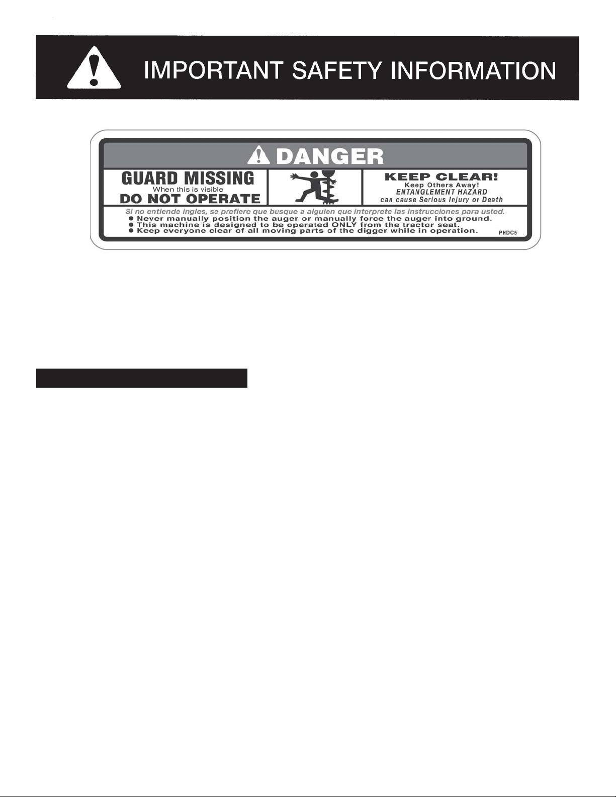
LOCA TION: TOP END OF AUGER TUBE
P ART NUMBER: DL52020500
NOTE: IF THE OUTPUT SHAFT GUARD MENTIONED IN THE ABOVE DECAL IS MISSING ,YOU
MA Y ORDER A REPLACEMENT BY CALLING US AT 1-800-525-8322.
GENERAL SAFETY AND PREPARA TION
ALWAYS make sure that anyone else who operates this post hole digger has read and understood the contents of the
owner’s manual and all safety decals on the product.
ALWAYS be certain that all members of the work party are familiar with the operation of the digger and the hazards
associated with it.
ALWAYS check with authorities for underground utilities before digging a hole. Serious injury or death could result from
contact with gas or electric lines.
ALWAYS check the tractor owner’s manual for instructions on operation, attachment of 3-point equipment and safety .
ALWAYS make sure that all safety shields are in place and tightened down. Do not operate this post hole digger if any
shields are missing. Contact SpeeCo, Inc. at 1-800-525-8322 for replacement p art(s).
ALWAYS make sure that the auger point and cutting edges are intact and in good working order before using this digger.
NEVER allow children or other persons to ride on the Tractor or Implement. Falling off can result in serious injury or death.
NEVER allow children to play on or around Tractor or Implement. Children can slip or fall off the Equipment and be injured
or killed. Children can cuase the Implement to shift or fall crushing themselves or others.
NEVER allow others within 20 feet while operating the post hole digger.
NEVER operate post hole digger without all guards in place.
ALWAYS ensure the driveline is securely locked onto the PTO.
Page 3
Page 6

OPERA TING SAFETY
ALWAYS operate this post hole digger from the tractor seat.Only one person should operate the digger .
NEVER attach the post hole digger with the tractor engine running.
NEVER operate the post hole digger with anyone near or in contact with any part of the implement, PTO driveline or auger .
Serious injury or death could result from entanglement with moving parts.
ALWAYS make sure that the tractor brake is set before digging a hole.
ALWAYS keep hands, feet and clothing away from power-driven parts during operation.
NEVER manually position the auger or manually force the auger into the ground.
ALWAYS make sure that the tractor engine is shut off and the PT O drive is disengaged before leaving the tractor seat.
NEVER move the tractor with the power-take-off in the ON position.
NEVER exceed 540 RPM PTO operating speed.
NEVER operate the post hole digger when the auger point is more than 6 in. above ground level. Operating the digger in
elevated positions may cause the PTO driveline “U” joints to bind resulting in equipment damage and operator injury .
ALWAYS turn of f the digger immediately if an immovable object is encountered to prevent damage to the gear box or
driveshaft and possible injury . A shear bolt is provided but may become welded to the input shaft if the driveshaft is left
running after being sheared.
.
TRANSPORT ATION SAFETY
NEVER allow anyone to ride on Implement.
Make certain the slow moving (SMV) sign and other reflectors are clearly visible. Follow local traffic codes for slow moving
vehicles when transpotting on public roads.
REP AIR AND MAINTENANCE SAFETY
ALWAYS perform maintenance operations such as lubrication, adjustments or repairs on the post hole digger with the
tractor engine off, the PTO drive disengaged and the auger point resting on the ground.
ALWAYS use the correct shear bolt (Grade 5). NEVER use or replace the shear bolt with one that is longer than the one
specified in the manual (5/16” x 2-1/2”).
Periodically inspect all moving parts for wear and replace when necessary with authorized service parts. Look for loose
fasteners, worn or broken parts, and leaky or loose fittings. Serious injury may occur from not maintaining this machine in
good working order.
Do not modify or alter this Implement. Do not permit another to modify or alter this Implement, any of its
components or any Implement function. Any modification will void the warranty.
Page 4
Page 7

ASSEMBLY INSTRUCTIONS
IMPORT ANT: The gear box is shipped without lubricant. Fill the top hole with 80W-90 lubricant or the equivalent.
Approximately 1.75 quarts of the lubricant is enough to lubricate the gears and bearings. A
greater amount will not harm the gear box. Do notfill to overflow point as this may damage the
seals.
STEP 1: Be certain that the gear box has adequate lubrication. Check the oil level after every fifty hours of
use.
STEP 2: Attach the boom (1) to the top link mounting bracket on the tractor using a top link pin and a
lynch pin (not provided) through the swivel ball at the bottom of the boom. The ball accepts
either category 1 or 2 pins.
STEP 3: Connect the “A” frame (5) to the tractor’s 3-point lift arms using the 7/8 in. pull pins with nut and
lockwasher (7) as shownin the drawing. Attach the “A” frame (5) to the boom (1) after selecting
the desired hole (for angle adjustment) using the “A” frame pin (6) and lynch pin (4).
STEP 4: Attach the gear box (10) to the boom (1) using the boom pin supplied with the gear box. When in
place secure with the cotter pins provided. NOTE: Input shaft shield (9) and output shaft shield
(8) are already attached to the gear box.
STEP 5: Attach the auger (18,19,20, 25 or 26 ) to the output shaft on the bottom of the gear box (10) using
the 1/2 in. hex cap screws (15), 1/2 in. lockwashers (16) and 1/2 in. hex nuts (17). Tighten the
nuts.
STEP 6: Attach the driveline (11) to the gear box input shaf t using the 3/8 in.grade 5 hex cap screw (12),
the 3/8 in.lockwasher (13) and the 3/8 in. NC hex nut (14). Tighten the hex nut. Insert the 1/4
in. x 3/8 in. set screw (24) from the hardware kit in the hole on the yoke that aligns with the 3/16
in. groove on the gear box input shaft. T ighten loosely .
ATTENTION: THE 3/8 IN. HEX CAP SCREW PROVIDES SHEAR PROTECTION. USE A GRADE 5
3 IN. BOL T ONL Y TO A VOID DAMAGE TO THE GEAR BOX OR AUGER.
IMPORT ANT: The universal joint should be greased with a good grade chassis lube every week. At the
beginning of each season grease the sliding driveshaft members with a moly grease. All
diggers are equipped with quick-detach universal joints on the power-take-off end for a
1-3/8 in. splined shaft.
STEP 7: Attach the tractor end of the driveline (1 1) to the tractor PTO shaft. Push in the spring-loaded pin
in the splined yoke and slip it on the splined PTO shaft of the tractor. Release the pin and push
until it locks securely in place. It will be necessary to obtain a 1-1/8 in. to 1-3/8 in. sleeve spline
adapter if your tractor PTO shaft has a 1-1/8 in. spline.
STEP 8: Attach and secure the lower chain on the driveline to the boom (1). Attach the upper chain to the
hole on the gear box shield (9).
STEP 9: Check all nuts and bolts for tightness. S tabilizers should be kept tight to avoid side sway of the
digger.
NOTE: See illustration A for reference in assembling the digger and mounting it to the tractor. Note that
the boom angle can be adjusted on your tractor for proper digging and ground clearance by
moving the “A” frame to a different mounting hole as shown in illustration B.
NOTE: When the 7/8 in. diameter pull pins in the “A” frame are too small for the holes in the lift arms,
bushings should be used to obtain a proper fit
Page 5
Page 8

Angle
Adjustment
Angle
Adjustment
ILLUSTRATION A
ILLUSTRATION B
OPERATING INSTRUCTIONS
WARNING: Read and thoroughly understand all instructions and safety information before operating
this post hole digger Failure to do so may cause serious injury or death. Do not allow anyone to
operate this post hole digger who has not read this manual.
STEP 1: Af ter mounting the digger to the tractor , lower the auger point slowly to the ground at the desired digging
angle before engaging power.
STEP 2: Engage the power-take-off and start digging at a slow speed, lowering the auger slowly as it begins to dig.
STEP 3: Increase speed as the auger goes deeper . The type of soil will determine the proper auger speed. If the
soil is extremely hard, it will generally improve operation to vary the speed of the auger at times.
STEP 4: When the auger has reached the desired depth, spin it momentarily at a high speed to clear the hole of
dirt. Reduce speed before withdrawing the auger from the hole.
STEP 5: Disengage the power-take-off after withdrawing from the hole and move the tractor to the next hole location.
GENERAL MAINTENANCE
REFER TO ILLUSTRATION C
WARNING: Always perform maintenance operations with the tractor engine off, the PTO drive disengaged
and the auger point resting on the ground.
1. To remove the auger from the gear box output shaft, take out the two 1/2 in. x 3-1/2 in. hex cap screws (15).
2. To remove the driveshaft from the gear box input shaft, take out the shear pin bolt (12) and 1/4 in. set screw (24).
3. Check the oil level after every fifty hours of use. Use 80W-90 lubricant and fill to oil level plug. All replacement
lubricant should be of this type.
4. The universal joints should be greased with a good grade chassis lube every week. At the beginning of each
season, grease the sliding driveshaft members with a moly grease.
Page 6
OPERATING INSTRUCTIONS
Page 9

MODEL POST HMRTS BREAKDOWN
HEAVY DUTY POST HOLE DIGGER
PARTS BREAKDOWN
ECNEREFER
REBMUN
100168042mooB1
200957042niPxoBraeG/mooB1
4L/OniPhcnyL.ni61/71
500068042emarF
600107070niPemarF"A"1
700802070rehsawkcoLdnatuNhtiwniPlluP.ni8/72
800357042drauGtuptuOxoBraeG1
900257042drauGtup
0100457042sdleihS/wxoBraeG1
11ZH051142dleihScitsalPhtiwenilevirD1
A1100171142ylbmessAdrauGenilevirD1
B110
C11ZH951142ekoYdnEtnemelpmI1
D11ZH551142tiKgniraeBdnassorC2
E11L/OwercSteSdetnioP"8/3x"4/11
21L/O
31L/OrehsawkcoL.ni8/31
41L/OtuNxeHCN.ni8/31
51L/OwercSpaCxeH.ni3xCN.ni2/
61L/OrehsawkcoL.ni2/12
71L/OtuNxeHCN.ni2/12
8100112142reguA.ni61
9100412142reguA.ni91
0200712142reguA.ni211
3200912142tnio
42L/OwercSteS.ni8/3x.ni4/11
5200845042reguA.ni811
6200945042reguA.ni421
TRAP
REBMUNNOITPIRCSED
00064042reguAsselreggiDeloHtsoPytuDyvaeH1
"A"1
nIxoBraeG1
0021142ekoYniPhsuP1
raehS5edarG(wercSpaCxeH.ni3x.ni8/3
)tloB1
12
PwercS1
REBMUN
DERIUQER
NOTE: All augers are sold sep arately .
avasrenetsafnommoC.yllacolniatbO-L/O
.serotsmrafdnaerawdrahhguorhtelbali
Page 7
Page 10

HEA VY DUTY DIGGER
ILLUSTRA TION C
Page 8
Page 11

CUTTING EDGES AND POINT PARTS BREAKDOWN
O/L- Obtain locally . Common fasteners available through hardware and farm stores.
*NOTE:The number of cutting edges varies by auger size. Check your auger
6 inNumber of Cutting Edges
Per Auger
6 in. (24121 100)- 2
9 in. (24121400)- 2
12 in.(24121700)- 4
18 in.(24054800)- 4
24 in.(24054900)- 6
ECNEREFER
REBMUN
100222112egdEgnittuCedibraCreguaybseirav
2L/OtloBegairraC
3L/OtuNkcoLCNU"2/1egdegnittucrep1
4L/OtloB"2/1-3x"2/11
5L/OtuNkcoL"2/11
600912142tnioPreguA1
when ordering replacement cutting edges. See information below.
TRAP
REBMUNNOITPIRCSED
ILLUSTRA TION D
REBMUN
*DERIUQER
CNU"1x"2/1egdegnittucrep1
in. auger (
2
1
3
5
4
6
NOTE: It is important to replace the point and cutting edges when they show signs of excessive wear .
Page 9
Page 12

NOTES
Model No. ____________________
Date of Purchase _______________ Place of Purchase _______________________
_______________________
_______________________
_______________________
Page 11
Page 13

yrogetaCrotcarT2yrogetaCdna1yrogetaC
SPECIFICATIONS
xoBraeG raeghcaefosedishtobnosgniraebrellorderepatdnasraegnoinipyol
lalaicepS
enilevirD )dedleihsyletelpmoc(OTPenilps-6dradnatstifotekoyhcat-kciuqhtiwdeppiuqE
sreguA
apesdlos(.ni42dna.ni81,.ni21,.ni9,.ni6
segdEgnittuC)yletarapesdlos(edibrac,elbaecalpeR
tnioP)yletarapesdl
os(pitlaripS
mooB thgiehrofselohelpitlumdnabirderepathtiwgnibuthtgnertshgih.D.O.ni.ni4/1-3
tnemtsujda
ema
rf-Agnibuthtgnertshgih.ni4/1-3
sdleihsytefaS tfahstuptuoxobraegdnatnioj"U"xobraeg,enilevirdnO
tloBraehS .s
snoitpO tikgnitnuomthgiewdnatikecrofnwodciluardyH
ORDERING INFORMA TION
)yletar
raegdnaregua,enilevirdtcetorpottfahstupninO.elbaecalpeR
TRAP
REBMUNNOITPIRCSED
00064042reguasselreggidelohtsopytuDyvaeH
00112142 segdegnittucedibracelbaecalperdnatnioplaripshtiwregua.ni6
00412142 segdegnittucedibracelbaecalperdnatnioplaripshtiwregua.ni9
00712142 segde
00845042 segdegnittucedibracelbaecalperdnatniopla
00945042 segdegnittucedibracelbaecalperdnatnioplaripshtiwregua.ni42
00912142 sregua.ni
00222142 sregua.ni42dna.ni81,.ni21,.ni9,.ni6rofegdegnittucedib
00568042tiKtnuoMthgieW
00654042tikecrofnwodciluardyH
rac.ni2
ripshtiwregua.ni81
42dna.ni81,.ni21,.ni9,.ni6roftnioplaripS
).ezisreguaybseiravderiuqerytitnauQ(
gnittucedibracelbaecalperdnatnioplaripshtiwregua.ni21
Page 14

 Loading...