

Page 1

USB Cable
XDS560v2 System Trace JTAG Emulator for CCS 4.x
Quick Start Installation Guide
Kit Contents
+5V Universal
Power Supply
XDS560v2
System Trace
AC Power
Cords
Ethernet Cable
Driver DVD
MIPI60 – 20CTI
MIPI60 –20ARM MIPI60 – 60TI
MIPI60 – 14TI
System Requirements
• Microsoft Windows™ 2000/XP/Vista
• 2 GB of free hard disk space
• Minimum 1 GB RAM, 2 BG recommended
• Minimum 1.5 GHz, dual core recommended
• Color display
• Internet Access
• USB port
• Ethernet port
• DVD reader
Service and Support
Web http://support.spectrumdigital.com
E-Mail support@spectrumdigital.com
The driver install supports the Spectrum Digital XDS560v2
System Trace JTAG Emulator in a CCS 4.2 or higher
environment. Emulation drivers are updated on a regular basis
so check the Spectrum Digital web site at
support.spectrumdigital.com. The XDS560v2 System Trace
JTAG Emulator will be referred to as the XDS560v2 STM.
Installation Overview
Installing the XDS560v2 STM is 3 step process:
1. Installing the Code Composer Studio software
2.
Configuring the emulator tail with correct target
adapter.
3.
Installing the USB or Ethernet connection to the
host PC.
512106-4001B Page 1 of 4
12502 Exchange Dr., Ste 440, Stafford, TX. 77477 T:281.494.4505, F:281.494.5310 www.spectrumdigital.com
Page 2
Installing the Code Composer Studio software
1. Code Composer Studio should be installed before
starting the hardware installation. Please refer to the
Code Composer Studio software installation guide for
the installation of Code Composer Studio. The
baseline Spectrum Digital emulation drivers are
included in CCS v4.2 and higher and these should be
installed.
2. Additional documentation is on the driver CD included
with your XDS560v2 STM product.
Configuring the Emulator Tail
1. The emulator tail is the physical interface between the
emulator and target board. The tail configuration will
consist of 3 parts:
- Emulator tail header
- Emulator tail header to MIPI 60 pin header
- MIPI 60 to target JTAG connector adapter:
MIPI 60 to 20 pin CTI – installed at the factory
MIPI 60 to TI 14 pin
MIPI 60 to TI 60 pin
MIPI 60 to ARM 20 pin
2. The female JTAG header attached to the end of the
emulator tail plugs onto the target’s male pin header.
The figure below shows how the XDS560v2 STM
emulator header plugs onto the target’s JTAG header.
3. The figure below shows the factory installed
configuration, MIPI 60 to CTI20.
Installing the USB or Ethernet connection to the
host PC
This section provides instructions to install the XDS560v2
STM JTAG emulator using the USB or Ethernet interface.
1. Turn off the power to your target board.
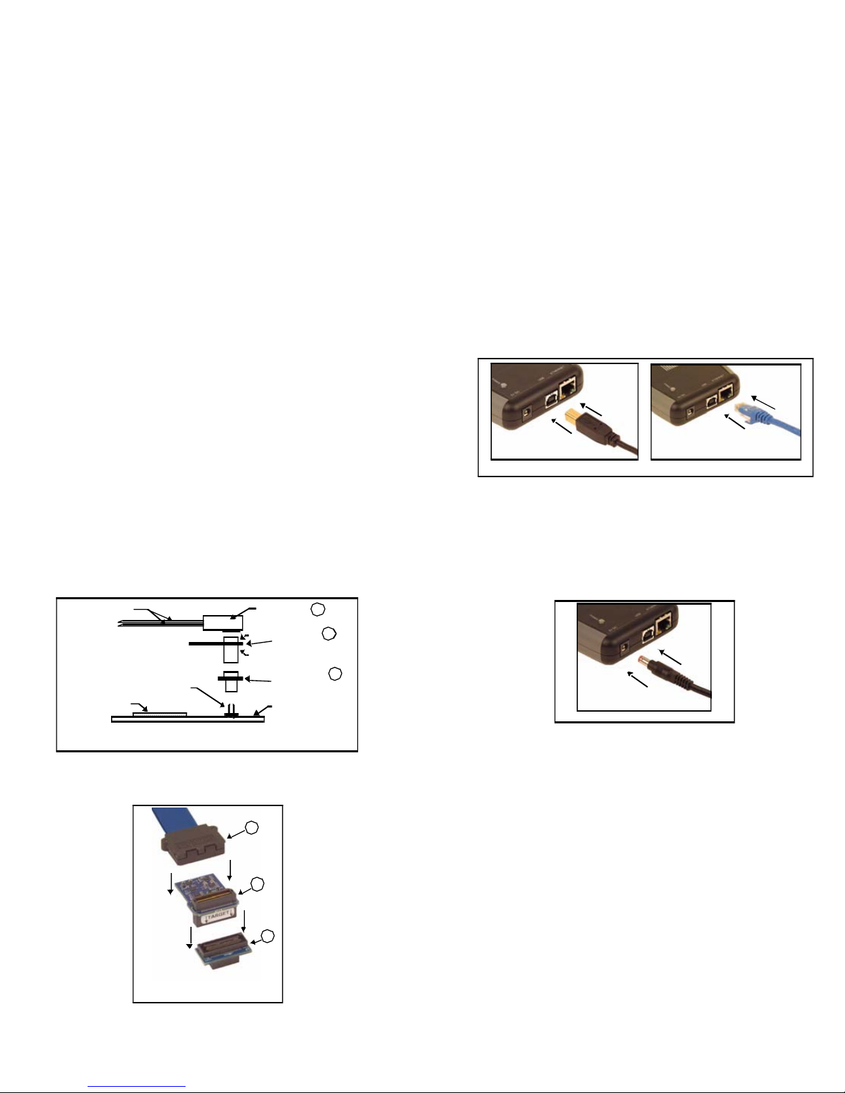
2. The XDS560v2 STM may be connected to the host
PC by either Ethernet or USB. Connect the supplied
Ethernet or USB cable to your PC or laptop. The
XDS560v2 STM may be used with an Ethernet router
or powered USB hub.
3. Connect the other end of the Ethernet and/or USB
cable to the XDS560v2 STM.
Connecting the Ether net and/or USB Cable to XDS560v 2 STM
4. Connect the included +5 volt power supply to your
wall AC power source using the AC power cord.
5. Apply power to the XDS560v2 STM by connecting the
power supply to the +5 volt input on the XDS560v2
STM located on the rear of the emulator.
Target Board
DSP
Emulator Tails
Co n nect ing t he XDS560 v2 ST M
JTA G Emulator to the DSP Target Board
J2
J1
Tail He ader
Header to
MI PI 60 Adapter
MIPI 60 to
Tar get JTAG
Adapter
Targe t JTAG
Connector
A
B
C
Ap plying Powe r to XDS560v 2 ST M
When power is connected the “PWR” LED on the
XDS560v2 STM should illuminate. After about 45
seconds LEDs “State 2” and “State 3” should come
on. At this point the XDS560v2 STM has booted its
operating system and is ready for connecting via USB
A
B
C
Tail plugs into MIPI60 which
plugs into CTI20 Adapter
or Ethernet.
If this is the first connection over the USB the
Windows Hardware Wizard should find the XDS560v2
STM and install its USB drivers.
512106-4001B Page 2 of 4
12502 Exchange Dr., Ste 440, Stafford, TX. 77477 T:281.494.4505, F:281.494.5310 www.spectrumdigital.com
Page 3

The figure below shows the Ethernet or USB cable,
power cord plugged into the XDS560v2 STM.
6. Now connect the tail of the emulator to the JTAG
header on your target board. If your target board
requires a different interface than the generic 60 pin
header on the tail, attach one of the header adapters
as required.
Caution should be used in the routing of the tail ribbon
cable to insure it does not go near the processor(s),
power traces, or power cords.
7. Apply power to the target board.
8. Please refer to the XDS560v2 STM Technical
Reference Manual for the typical system
configurations.
Configuring CCSv4
To configure CCS v4 to use the XDS560v2 emulator
follow the CCSv4 instruction for creating a “New Target
Configuration”. When selecting the emulator select one of
the following:
U SB Cab le and Power Cor d Attached to XDS56 0v2 STM
"Spectrum Digital XDS560V2 STM LAN Emulator" for
Ethernet connection or
"Spectrum Digital XDS560V2 STM USB Emulator" for
USB connection.
For an Ethernet setup you will need to configure the “The
Emulator IP Address” under the “Connections Properties”.
The IPAddress for your XDS560v2 can be obtained using
the XDS560v2 Configuration utility. There should be an
icon on your desktop named Sd560v2Cnfg.
Under the “Eth” tab you can select “FIND IPAddress” and
then match the MAC Address found to the MAC address
of your XDS560v2. The XDS560v2 MAC address is on
printed on the back of your XDS560v2. CCSv4 takes the
IP Address in the form of x.x.x.x for example 10.0.3.54.
Attaching the XDS56 0v2 STM Em ulator Tail To Targ et
Align the emulator tail over the target connector, then push down
Emulator tail attached to target
For USB the default “Emulator I/O Port Number” of 0
should be used when connecting to a single XDS560v2.
For other methods of finding the IPAdress or verifying your
XDS560v2 connection see the Sd560v2Cnfg help.
512106-4001B Page 3 of 4
12502 Exchange Dr., Ste 440, Stafford, TX. 77477 T:281.494.4505, F:281.494.5310 www.spectrumdigital.com
Page 4

512106-4001B Page 4 of 4
12502 Exchange Dr., Ste 440, Stafford, TX. 77477 T:281.494.4505, F:281.494.5310 www.spectrumdigital.com
 Loading...