

Page 1

Table of Contents
1. Description & Equipment Adjustments p.2
2. Components, Features & Functions p.3
3. Valve User Interface p.4
4. Installation Instructions p.5
5. Valve Initial Set-up p.6
6. Valve Operation p.7
7. End User Instructions p.8
8. Troubleshooting p.9
9. Cautions p.11
10. Technical Information p.12
Spectrum
TM
Installation, Service &
Operation Manual
SoftH2O FLO
Water Softener
Page 2

Spectrum
TM
2
Regeneration Mode
Regeneration Type
Electrical Supply
Installation Number Nominal Capacity
m3 °tH
Valve Serial Number Inlet Water Hardness
°tH
Resin Volume
litres
Treated Water Volume
litres
Outlet Water Hardness
°tH
Volumetric
m
3
1) Backwash
min
2) Brining & Rinse
min
3) Rapid Rinse
min
4) Brine Tank Rell
min
Low Voltage DC Transformer or Battery 2 x 1.5V A
1. Description &
Equipment Adjustments
Page 3

3
Spectrum
TM
2. Components, Features
& Functions
Component Features Functions
Automatic
Control Valve
• FDA approved Noryl plastic
• Strong corrosion resistance
• Innovative design
• 24 hours control and monitoring with a timer; automatically
regenerates the media bed at the system’s set time of
regeneration according to the set regeneration frequency.
• Cycle Process:
In service: Once the water is supplied with correct pressure
and ow, the cations contained in hard water will be replaced
by Na+ in regenerants, then the softening system will supply
softened water through its outlet.
Backwash: When the ion exchange resin has been
exhausted, the resin bed needs to be regenerated. Before
the regeneration of the resin bed, a backwash step is
necessary for two main purposes; removing the residue
in the resin bed and loosening the impacted resin bed for
better regeneration efciency.
Rinse: Rinse the resin bed to remove the residual regenerant
(salt) after the brining step until the water from outlet
contains no regenerant; rinse could also compact the resin
bed for a better softening effect.
Rell: Rell the brine tank with water to dissolve salt for the
next regeneration.
Valve Operation Mode Softener: Standard water softener operation
Regeneration Mode Volumetric
Water Hardness can be adjusted User can adjust the mixing valve to get desired water hardness
Display Format Metric format
Media
High-grade Anion exchange resin
(food grade 2 resin)
Pressure
Vessel
• NSF 44 tested and certied
• Polyethene material manufactured for the
Food & Beverage industries
• Light, high pressure resistance
• Strong corrosion resistance
Pressure vessel holds the resin and a distribution system
Riser Tube &
Distribution
System
A riser tube and distribution system disperse water evenly
through the resin bed
Brine Valve
& Tank
• High pressure resistance
• Prevents the brine tank from overowing
• Water and salt mix in the brine tank. Salt will dissolve
continuously until the water is saturated by salts
Page 4

Spectrum
TM
4
3. Valve User Interface
Brine Line
Drain Line
Blending Valve
Inlet
Outlet
Regeneration Indicator
Parameter Display
Flow Rate Indicator
Regeneration Button ( R )
Next Button ( )
Up Button ( )
Down Button ( )
Time Display
Cycle Nº
Bypass
Page 5
5
Spectrum
TM
4. Installation Instructions
The softener needs to be installed on the mains
water. It has an integrated bypass. Piping has to
comply with the regulations of the country where it
is installed.
• Do not plug in the electrical feed before the
installation.
• Ensure the stopcock is closed.
• The piping of the inlet and outlet are ¾” BSP.
• The water needs to have a pressure between 2-8
bar and 4-42 degrees.
• The softener has to be installed on a at dry surface.
• Electrical mains powered 220-240V AC 50Hz for plug model.
• The soldering on the pipework has to be done before connecting the water softener as heating could damage the
water softener.
• For residential purposes, it is essential to ensure that at least one drinking water tap is not connected to the
softener. Softened water has a high Sodium content which is to be avoided for people on low sodium or salt diets,
babies on infant formulas.
5
4
5
5
4
6
6
Water Pressure 2 - 8 bar
Electrical Supply Uninterrupted AC
Existing Plumbing
Free of any deposits or build-ups
inside pipes
Softener Location
Locate close to drain & connect
according to plumbing codes
Bypass Valves Always provide external bypass valve
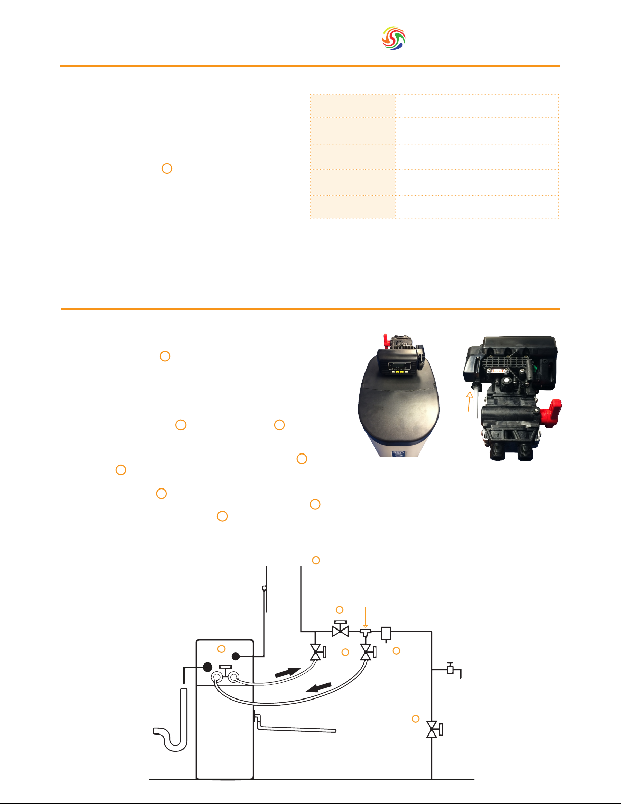
4.1. Connecting
1. Rotate the valve so that the electronic display faces the ip top
lid on the softening system. (Fig.A)
2. Insert white brine tube inside the push t valve connector. (Fig.B)
3. Close the stop cock.
4. Connect the drain Line to the the outside drain of the premises.
It is necessary to t an air gap device.The drain piping should be
as short as possible avoiding height of over 1.5 metres higher
than the softener as well as lengths of over 5 metres.
5. Connect the inlet and outlets to the tted plumbing.
6. Close the bypass valves. Open the stopcock and open the
water at the feed tap. This will allow any particles to be removed
from the system before operation. Let water run out of the tap
until it is clear. Once done, close both the outlet tap and the
stopcock to pursue further steps of the installation.
7. Manually ll the brine tank with water between 5 and 10 cm.
8. Open the bypasses as well as the stop cock . You will hear the water owing into the resin pressure vessel. When
there is no more water owing in, open a cold water tap so that the excess air will purge out of the system. Once
the air is removed, close the tap.
9. You can now switch on the valve electrical power.
10. Press the R button for 5 seconds twice to allow a regeneration. It will last between 30 minutes and 1 hour.
6
5
Mains Out
Power
Supply
Drain
Hose
To Drain
Water Softener
In Out
Overow To Outside
Main Water
Supply
Mains
Stopcock
Main Water
Tap For
Drinking
Pressure Reducing
Valve (if required)
Bypass Valve
Inlet Tee
Incorporating
Check Valve
Outlet
Valve
Inlet
Valve
Internal
Bypass
1
2
3
4
5
6
Fig. A
Fig.B
Page 6
Spectrum
TM
6
5. Valve Initial Set-Up
5.2. Setting up the regeneration program
1. Push the “DOWN / ” button until the time displayed is 23:45.
2. Push the “NEXT / ” button for 8 seconds until r_ _ (VALUE) is displayed.
3. Push the “UP / ” button until r-3 is displayed.
4. Press the “NEXT / ” button until t-df is displayed.
5. Press the “NEXT / ” button until F-(VALUE) is displayed.
6. Press the “UP/ ” or “DOWN / ” button until F-05 is displayed.
7. Press the “NEXT / “ button until 1F-(VALUE) is displayed.
8. Press the “UP / ” or “DOWN / “ until reaching the value
determined in chart 1. (i.e. an 18l softener with 200ppm = 4.5)
9. Press the “NEXT / ” button until 1-(VALUE) is displayed.
10. Press the “UP / ” or “DOWN / ” button until you reach the value
determined in the regeneration cycle setting chart for cycle 1 for your
specic softener.
11. Press the “NEXT / ” button until 2-(VALUE) is displayed.
12. Press “UP / ” or “DOWN / “ until you reach the valued determined
in the cycle setting chart for cycle 2 for your specic softener.
13. Press the “NEXT / ” button until 3-(VALUE) is displayed.
14. Press the “UP / ” or “DOWN / ” button until you reach the value
determined in the cycle setting chart for cycle 3
15. Press the “NEXT / ” button until 4-(VALUE) is displayed
16. Press the “UP / ” or “DOWN / ” button until you reach the value
determined in the cycle setting chart for cycle 4
17. Press the “NEXT / ” button until the regeneration time is displayed
(VALUE).H1
18. Using the “UP / ” or “DOWN / ” buttons set the time to a
convenient one, when you are less likely to use water i.e. 3.H1 = 3AM
19. Press “NEXT / ” button oF:H2 will be displayed
20. Press “NEXT / ” button oF:H3 will be displayed
21. Press “NEXT / ” button oF:H4 will be displayed
22. Press the “NEXT / ” button so that a time will be displayed.
23. Adjust to the correct rime of day using “UP / ” or “DOWN / ”
then your softener is ready to work.
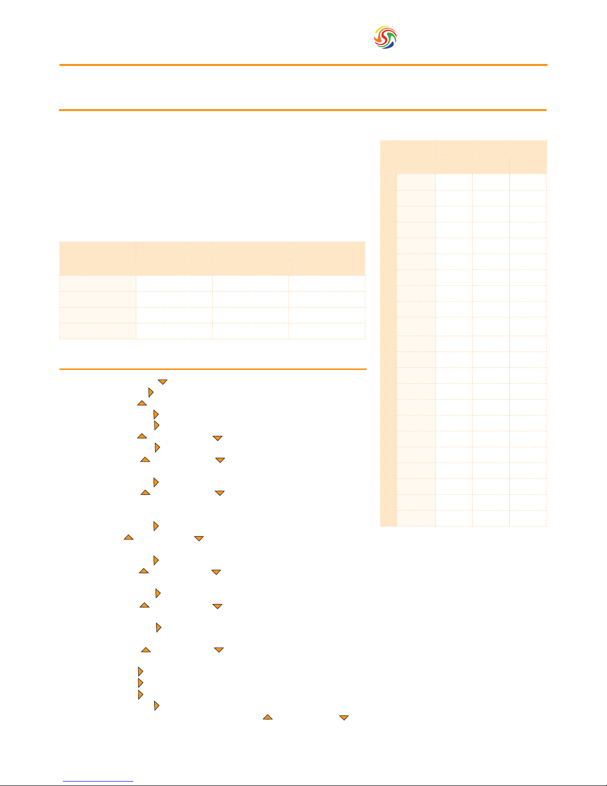
5.1. Programming
Hardness
Settings
Resin Volume (L)
13 18 25
100 6.5 9.0 12.5
120 5.4 7.5 10.4
140 4.6 6.4 8.9
160 4.1 5.6 7.8
180 3.6 5.0 6.9
200 3.3 4.5 6.3
220 3.0 4.1 5.7
240 2.7 3.8 5.2
260 2.5 3.5 4.8
280 2.3 3.2 4.5
300 2.2 3.0 4.2
320 2.0 2.8 3.9
340 1.9 2.6 3.7
360 1.8 2.5 3.5
380 1.7 2.4 3.3
400 1.6 2.3 3.1
420 1.5 2.1 3.0
440 1.5 2.0 2.8
460 1.4 2.0 2.7
480 1.4 1.9 2.6
500 1.3 1.8 2.5
600 1.1 1.5 2.1
Hardnes Level in ppm CaCO
3
The capacity of your softener will depend on the hardness of your water.
First of all, check Chart 1 to the right, depending on your softener model
13, 18 or 25 L
The volume given in Chart 1 will be the volume of soft water produced
between 2 regenerations in m3.
As an example, if you have a 18L softener with a hardness of 360ppm, your
capacity will be 2.5m3. This is the value you should set in the program.
Cycle
Settings
Softener Model
13 18 25
Cycle 1 5 6 7
Cycle 2 21 25 30
Cycle 3 4 4 5
Cycle 4 4 6 8.5
Chart 1: Softener Water Capacity Chart
Chart 2: Regeneration Cycle Chart
Page 7

7
Spectrum
TM
6.1. Operation in service mode
• Once your softener is running, you can view the time of day. By pressing “NEXT / ” for a few seconds, you will be
able to see the remaining capacity of soft water left.
• Once the capacity is expired, a ashing (CIRCLE) will be displayed on the screen, indicating a regeneration will be
programmed at the time determined in the program.
• Regeneration will cause the machine motor to run, creating a mechanical noise, this is normal.
6. Valve Operation
6.2. Adjust the Time of Day
• Push the “UP / ” and “DOWN / ” buttons to set the correct time.
NB. The display of a valve using a low voltage transformer will blink during power failure. This blinking will end once
the programming has been restored.
6.3. Displaying the Remaining Volume of Water to be Treated (Metered System Only)
• Push the “NEXT / ” button to switch between the time of day and the remaining volume display.
6.4. Initiate a Regeneration
• Push the “regeneration / R” button for one second to initiate regeneration (the system will regenerate immediately for
a valve in “immediate regeneration mode” or at the next pre-set time for a valve in “delayed regeneration mode”).
• Push the “REGENERATION / R” button for 5 seconds to initiate regeneration immediately for a valve that is
programmed in “chronometric” or “volumetric” mode. This is to be used to ush the system after a long time such
as returning from holidays.
6.5. In Service
• The display will show the time of day during normal operation and will turn off after 3 minutes to conserve battery
life for battery operated models. The remaining volume of water to be treated can be displayed by pushing the
“NEXT ” button.
Page 8

Spectrum
TM
8
7. End User Instructions
Once the softener has been installed and setup by a professional, there are some useful functions to be aware of.
Salt replenishment: when the softener runs out of salt, it will not produce any more soft water. It is therefore impor-
tant to keep it topped-up, this is done via the lid of the top of the softener. Salt should always be visible over the line
of water in the cabinet but the total volume of salt and water should not exceed the overow level.
NOTE: ONLY USE GRANULATED OR TABLET SALT DEDICATED TO
WATER SOFTENERS
Bypass: The Bypass is a function which makes the water softener ofine.
This is useful when soft water is not required (e.g. using a hosepipe)
In the service position, the softener will produce soft water.
In the Bypass position, the water will not go through the resin tank and
remain as hard water.
Blending Valve: This can be used optionally when some
applications require a certain level of hardness. When
the blending valve is closed (Fully turned clockwise), you
will get 100% soft water. The more you open it (turning
anticlockwise), the harder the water will get.
Display: In service, the valve will go in power saving mode and will not
display information.
• Press “regeneration / R ” button and the display will be active again,
displaying the time of day.
• By pressing “NEXT / “ you will display the amount of water left
before the next regeneration is planned.
• If the symbol (Little circle with an arrow) is ashing, it indicates that
your softener will regenerate at the programmed time.
Regeneration is a standard process required to recharge the resin
contained inside the softener. The regeneration will happen at the time
set in the program. A motor noise can be heard when the softener is in
regeneration mode, this is normal.
The screen will display the various cycles of the regeneration and will then
go back to service mode.
• Backwashing
• Brining
• Rinse
• Rell
Power Cuts: Your softener will keep its parameters in memory for up to 48 hours. After that, reprogramming may be
necessary. Please refer to the programming sheet in the installer part of the manual.
Downtime: After holidays, or a long period without using water over a week, it is recommended to initiate a manual
regeneration in order to ush the resin tank.
Press the “regeneration / R ” button to bring up the display, press “regeneration / R ” again for 5 seconds in order to
program a delayed display (little circle ashing) and press a third time 5 seconds to start immediately. The cycle will
nish after approximatively one hour.
‘Service position’
shown.
Moving the red
lever upwards to
a vertical position
will put the valve
into the ‘Bypass
position’.
Front view shows
display/controls.
13 Litre Flo
System.
Lid
Overow
!
Page 9

9
Spectrum
TM
Problem Possible Cause Possible Solution
A. Controller does not work
1. Power off
2. Transformer is not plugged in
3. Defective power cord
4. Defective transformer
1. Switch on power
2. Connect to constant power source
3. Replace cord
4. Replace the transformer
B. Incorrect time of regeneration 1. Power outage causes inaccurate timing 1. Reset the timer
C. Leaking 1. Loose connections 1. Tighten joints
D. Noisy 1. Air pressure in the system 1. Re-backwash the system to vent air
E. Milk-white water 1. Air exists in the system 1. Turn on the tap to vent air
F. Unsatised water hardness
1. Poor raw water quality
2. Time of regeneration is too long
3. Resin disabled
1. Contact your supplier for assistance
2. Reset time of regeneration
3. Re-regeneration or use new resin
G. Softener fails to use salt
1. Water pressure is too low
2. Brine line blocked
3. Injector is blocked
4. Internal control leak
1. Line pressure must be at least 20 psi
2. Clean brine line
3. Clean or replace injector & screen
4. Check piston, seals and spacers
H. Brine container overow 1. Rell time too long 1. Contact your supplier for assistance
I. Water hardness remains
1. Fail to regenerate automatically
2. Brine concentration is poor
3. Injector is plugged
1. Check power of controller
2. Keep brine tank full of salt
3. Disassemble the injector and clear it
by washing with water
K. Untreated water leakage
during service
1. Improper regeneration
2. Leaking of bypass valve
3. O-ring around riser tube damaged
4. Incorrect regeneration cycle setting
1. Repeat regeneration making certain
that the correct salt dosage is set
2. & 3. Replace O-ring
4. Reset regeneration cycle
8. Troubleshooting
8.1. FLO System
Page 10

Spectrum
TM
10
8. Troubleshooting
8.2. FLO Valve
Problem Possible Cause Possible Solution
A. The system will not regenerate
1. Used or defective batteries
2. Disrupted electric supply
3. Damaged meter cable
4. Water meter turbine blocked
5. Defective drive motor
6. Defective electronic board
1. Replace old batteries
2. Recover the power supply
3. Verify the connection & inspect cable
4. Clean or replace the turbine
5. Replace the drive motor
6. Replace the electronic board
B. There is hard water coming
from the outlet
1. No salt in the brine tank
2. System in bypass position
3. Internal leak in valve
4. Dirty breech
5. Low brine tank rell
6. See symptoms in “A”
1. Rell the brine tank
2. Return the system to service position
3. Change the internal seals
4. Clean the breech
5. Change the two breech seals
6. See resolution in “A”
C. Decrease in pressure and ow
1. Iron build up in the water supply
2. Iron build up in the system
3. Levels of iron too high in the feed water
1. Clean or replace the supply line to
the system
2. Clean the valve and the resin bed.
3. Increase backwash time to prevent
fouling. Specically install an additional lter to remove iron.
D. High levels of brine present in
the brine tank
1. Clogged drain line
2. Defective cycle time
1. Check and clean the drain line
2. Adjust the cycle times
E. The outlet water tastes “salty”
1. Clogged injectors
2. Clogged drain line
3. Clogged brine valve
4. Defective cycle time
5. Damaged drain ow control
1. Clean the injectors
2. Check the drain line and ow control
3. Clean or replace the piston assembly
4. Adjust the cycle time
5. Change the ow control
F. There is a constant leak during
normal operation
1. Defective seal
2. Defective piston
3. Control valve blocked in regeneration
4. Defective power head
1. Change the seals
2. Change the piston
3. Change the piston and the seals and
spacers
4. Change the power head
G. Valve regenerates continuously
1. Defective power head 1. Change the power head
Page 11

11
Spectrum
TM
9. Cautions
1. Without reading and understanding the contents of this user manual, DO NOT perform any operations on the
control valve.
2. Strictly prohibit a leaning position when shipping, installing and using this product as this could cause damage.
3. During the regeneration, water from the tap will NOT be softened. It is NOT recommended to use water during
regeneration; otherwise a negative effect on the regeneration result will occur.
4. Initiate a regeneration cycle when the softener has been inactive for a long period of time and then turn on the
tap for several minutes before resuming normal use.
5. Do not disconnect power during service to prevent timer distribution.
6. If water usage or hardness of raw water dramatically increases (compared to the normal usage), then the frequency
of regeneration should increase.
7. Hot water could cause severe damage to the softener system, for water boiler and water heaters users, ensure the
total-run of the piping between the softener and the boiler is not less than 3 metres. It is recommended to install
a check valve between the lter and the boiler if unable to meet the required piping length.
8. The input water pressure must be between 2-8 bar.
9. No chemicals should be present at the inlet and outlet connecting sectors.
10. Besides the system, spare part connection materials are not included in the scope of the manufacturer’s warranty.
11. The required environmental temperature for a softener is 1-42°C. Outside these parameters may cause the
softener to malfunction.
12. Do not apply pressure to the softener.
13. Indoor installation is preferred. Avoid exposure to direct sunlight, radiation from other heating sources and avoid
extreme weather conditions including rain and snow.
14. Use salt granules or tablets designed for softeners.
15. No tools should be used for connecting the plastic parts as over tightening or excessive force could result in
damage.
16. If necessary use food grade silica sealant for lubricating rubber O-rings.
17. Only qualied personnel should adjust or remove the adaptor locking clips on the reverse of the valve, as this can
tamper with the valve settings. Should this be required pressure must rstly be discharged from inside the water
softener.
Page 12

Spectrum
TM
12
10. Technical Information
Maximum Operating Temperature (ºC)
42
Minimum Operating Temperature (ºC)
1
Maximum Operating Pressure (bar)
8
Minimum Operating Pressure (bar)
2
Hydrostatic Test Pressure (bar)
20
Max Flow Rate (m3/hr)
4.5
Inlet / Outlet (")
¾
Pressure Tank Thread (")
2.5
Valve
SPECTRUM 5
Power Requirements (V)
230
Salt Storage (kg)
10 14 21
Resin Volume (l)
13 18 25
Nominal Flow Rate (m3/hr)
0.5 0.6 1
Salt Consumption Per Regeneration (kg)
1.5 2 3
Water Consumption Per Regeneration (l)
78 90 133
Cabinet Width (mm)
330
Cabinet Depth (mm)
470
Cabinet Height (mm)
660 870 1100
 Loading...