

Page 1

1
2000 Series
Weather Stations
PRODUCT MANUAL
Model #’s
2900ET, 2800, 2700, 2550
Page 2

2
QUICK START
1. Check the Box
Verify all components are included
Pg 5
2. Set up Anemometer & Install the
Station
Pg 8 - 9
3. Configuring the Weather Station
Setting the logging interval, sensor type,
geographic data, and degree day calculation
Pg 13 - 17
4. Keypad Operations
Setting date, time, display units, degree
day counter, chill hour counter.
Pg 18 - 22
5. Daily Archive
Accessing the daily data
Pg 25
6. Battery Replacement Pg 26
7. Clearing the Logger’s Memory Pg 27
8. LCD Display Descriptions Pg 28, 29
Page 3

3
LCD Screens 28
Degree Days/Chill Hours 30
Rain Collector Adjustment 31
Warranty 32
CE Declaration of Conformity 32
CONTENTS
General Overview, Package Contents 4
Specifications 6
Anemometer Setup 8
Station Installation 9
Connection Options 10
Configuring the Weather Station 12
Configuring the Weather Station with SpecWare 13
Configuring the Weather Station with the Keypad 14
Setting the Logging Interval 14
Setting the Sensor Type 15
Setting Geographic Data for the ET Report 16
Setting the Degree Day Calculation Method 17
Other Keypad Operations 18
Setting the Date and Time 19
Setting the Display Units 20
Setting the Degree Day Counter 21
Setting the Chill Hour Counter 22
Configuring the Wireless Radio Address 23
Calibrating the Wind Vane 23
Resetting the Rain Counter 24
Resetting the Disease Models 24
Daily Archive 25
Battery Replacement 26
Clearing the Loggers Memory 27
Page 4

4
Thank you for purchasing a WatchDog 2000 Series
Weather Station. The stations are completely weatherproof and feature 12-bit resolution for higher accuracy. The stations can be accessed at different times
by multiple users because the data is not cleared
from memory following a download. The 2000-Series
weather stations can communicate via direct-wire,
radio or telephone connections.
Current weather conditions, historical data, and computed parameters are easily viewed on the station’s
LCD screen. The station LCD can also be programmed to display a variety of plant disease infection potentials. The arrow keys can be used to program the station’s logging interval and assign sensors to the external sensor ports. You can also
scroll through the sensor readings, Degree Day/Chill
Hour calculations and set your temperature ranges.
General overview
Model 2800 Stations
The model 2800 station is equipped with 9 external
sensor ports. It can be connected to any WatchDog
external sensor. This station is unique in that it has
no internal sensors. It is not possible to collect data
for air temperature, relative humidity, and wind
speed/direction. Therefore, the station cannot calculate Growing Degree Days, Chill Hours, Wind Chill,
Dewpoint, Evapotranspiration or any Disease Models.
Although a rain collector is not included as a standard sensor, it can be added as an optional external
sensor.
Page 5

5
Package Contents
Your 2000 Series Weather Station package should contain the following components:
Manual
Weather Station
Parts Box
Wind Vane
Wind Cups
4 AA Batteries
Ground Screw
Allen Wrench
Mounting Hardware - used to attach station to
Pole
Other tools needed, but not included:
Phillips screwdriver
Ground screw bottom clamp
Specifications
Data capacity
8800 data intervals. For example, for a 30-min interval, the station will run for 183 days before wrapping data.
Size
2900ET, 2700:
12 in (30 cm) x 8.5 in (21.5 cm) x 12 in (30 cm)
2550, 2800:
10 in (26 cm) x 8.5 in (21.5 cm) x 3.5 in (8.5 cm)
Weight (with rain collector and anemometer)
6.4 lbs (2.9 kg)
Power Source
4 AA batteries
Battery Life
10 months with alkaline batteries, 12 months with Lithium
Available External Sensor ports
6 (5 on model 2900ET, 9 on model 2800)
Included Sensors
The following table lists the specifications for sensors that are
included with the different models of weather station.
Page 6

6
Specifications (cont.)
Sensor Measurement Accuracy Available on
Wind Speed 0, 2-150 mph
0, 3-241 km/h
±2 mph (±3
km/h), ±5%
All but 2800
Wind Direction 1o increments ±4o All but 2800
Air
Temperature*
-40° to 125°C
-40° to 257°F
±0.3°C
±0.5°F
All but 2800
Relative
Humidity*
0% to 100%
@5° to 50°C
±2%
2550, 2700,
2900ET
Dew Point 2550, 2700,
2900ET
-73° to 60°C
-99° to 140°F
±2°C
±4°F
Rainfall 0.01” (0.25mm)
resolution
±2% at < 2 in
(5 cm) /hr
2600, 2700,
2900ET
Solar
Radiation
1-1500 W/m2 ±5% 2900ET
Operating Temperature Range: -22° to 130°F (-30° to 55°C)
Weather
Station
Firmware
Version
Number of
Sensors
Available
Channels
2550, 2700 6.9 2 A, D
2800 3.2 2 A, D
2900ET 6.9 1 A
For a Weather Station to be compatible with the SMEC300 sensor,
SpecWare software version 9.04 or later is required. See the following
table for the earliest compatible firmware and number of sensors that
can be used per station type.
* In 2016, Spectrum introduced a new T/RH sensor (3613WD). The
cable for this sensor emerges from the bottom of the radiation shield
rather than the side. A station must be running firmware v. 7.8 or higher to be compatible with this sensor.
Page 7

7
External Sensors
The following table lists the available optional sensors. All
sensors include a 6-foot cable with pin-type connector. To
connect an external sensor to the logger, plug the sensor cable
into the logger port that has been programmed for that particular
sensor. If the sensor is not connected, the message “sensor
error” will appear on the LCD display for the respective logger
port until the sensor is connected.
Item # Sensor Description
3666 Leaf Wetness
3667 (6ft), 3667-20 (20ft) External (Soil) Temperature
3670i Silicon Pyranometer
3668i 3668i3, 3668i6 Quantum Light
3669 Soil Moisture Transducer
6470-6 (6ft), 6470-20 (20ft) WaterScout SMEC 300 Soil Moisture/EC/
Temp Sensor
6460 (6ft), 6460-20 (20ft) WaterScout SM 100 Soil Moisture Sensor
6450WD (6ft), 6450WD20 (20ft) Watermark Soil Moisture Sensor
6451 Irrigation On/Off
3671 Barometric Pressure
3673, 3674 Input Cable for User Supplied Sensor
3664 20 ft. Sensor Extension Cable
Page 8
8
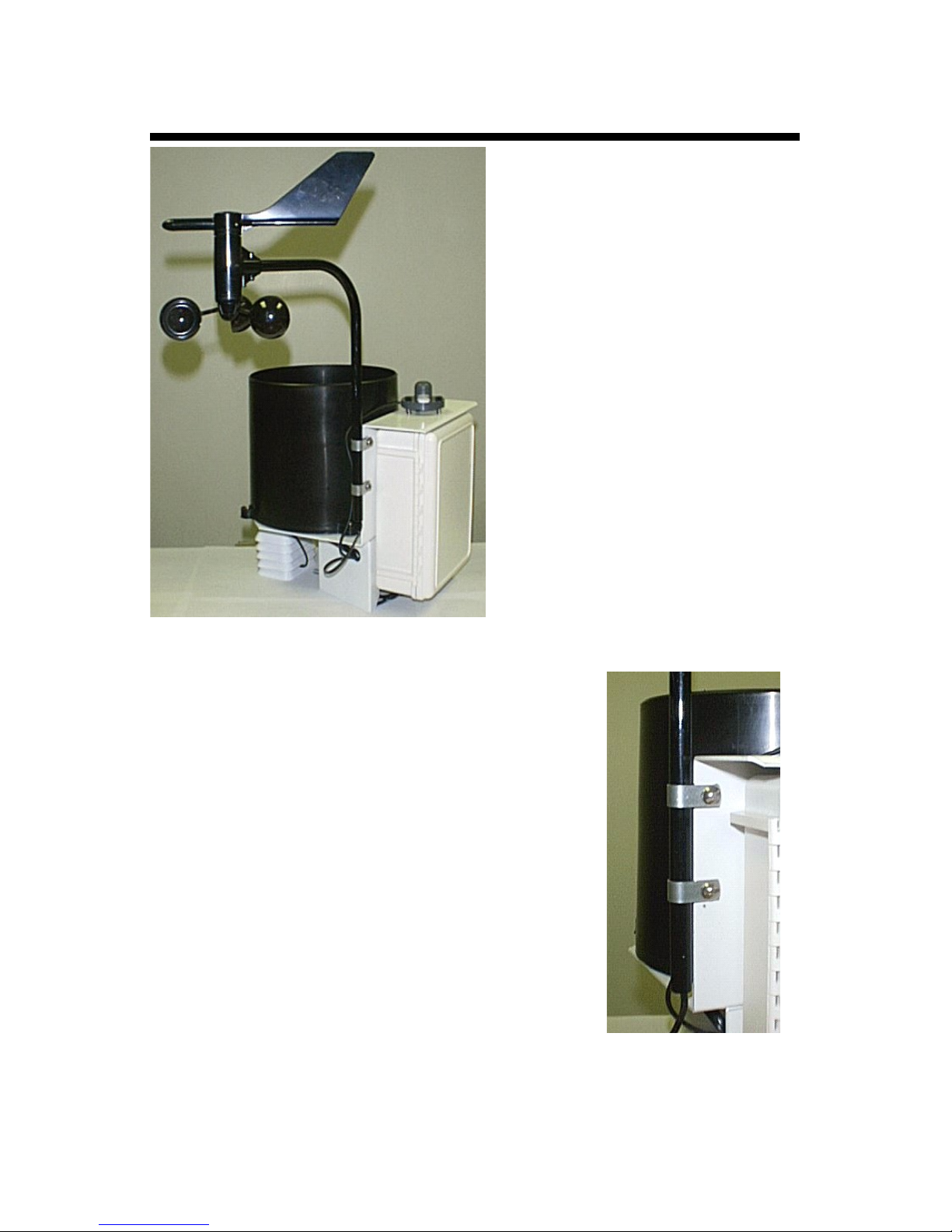
Anemometer setup
Apart from the anemometer,
the WatchDog Weather
Station comes fully assembled
and ready to mount. The
anemometer arm is attached
to the enclosure back plate
with two clamps. After
positioning the arm, the
screws should be tightened to
secure it in place.
A plastic envelope containing
a screw and a star washer are
included with the station. The
star washer should be used
under the screw holding the
bottom anemometer clamp.
Once the arm is positioned,
the self-tapping screw should
be screwed into the arm
through the hole drilled in the clamp. These parts improve
resistance to electrostatic discharge.
Push the wind cups onto the bottom of the
shaft flush with the bottom of the assembly
and tighten the set screw. When released,
the cups should drop slightly. If the cups do
not spin freely, loosen the set screw and
lower the cups slightly. The gap between cup
hub and assembly should be about 1/16 inch.
Push the wind vane onto the top of the shaft
and calibrate (see Calibrating the
Anemometer p. 23 for calibration procedure).
Anemometer clamped
to back plate
(unpainted clamps substituted for visibility)
Page 9
9
The weather station should be located in an open, unobstructed,
grassy area to ensure accurate measurement of wind, rainfall,
sunlight, and evapotranspiration.
Mounting hardware is provided to attach the weather station to a
4” x 4” treated wooden post or to a mast/pole up to 1.25 inches in
diameter. The mounting pole should be securely anchored
perpendicular to the ground.
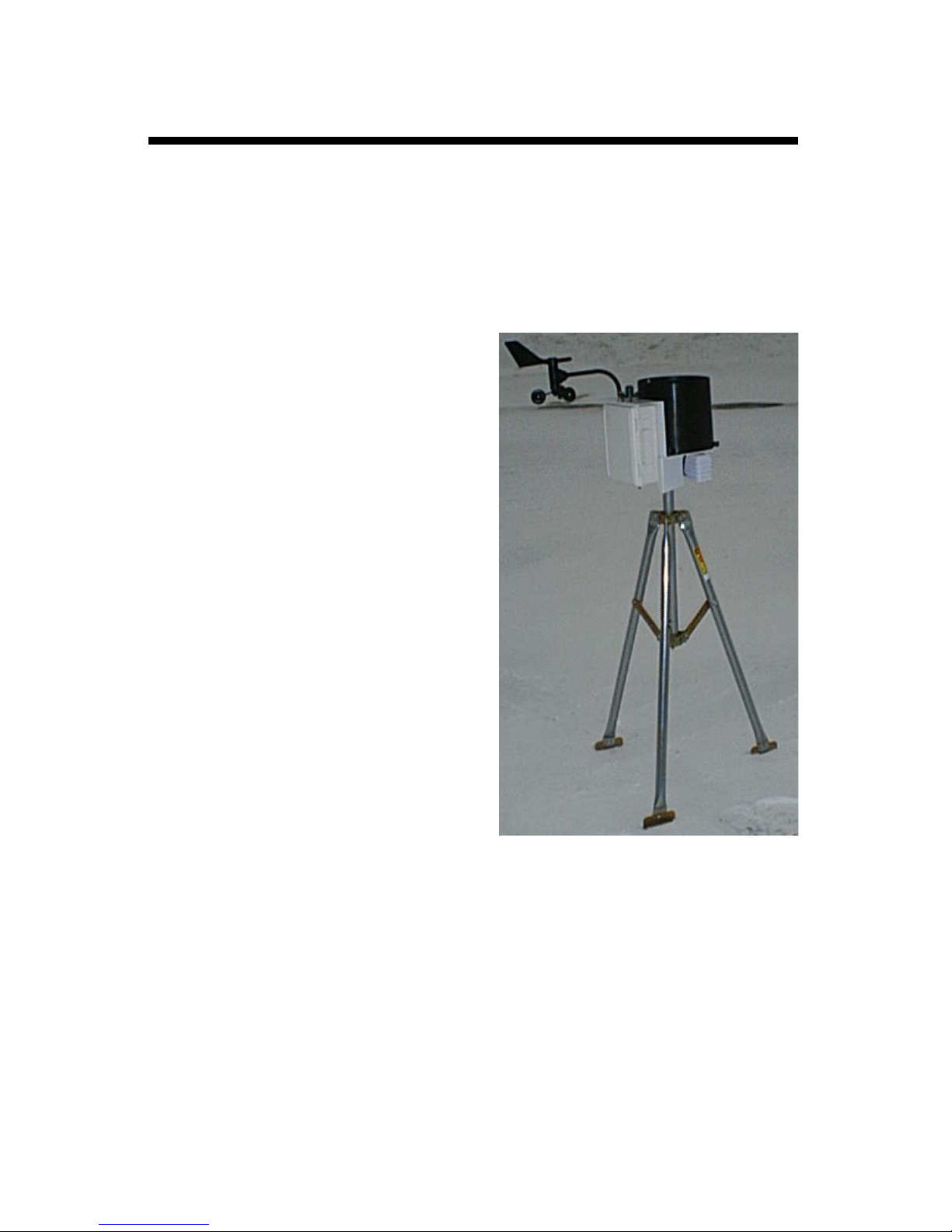
If you are using the mounting
tripod (item # 3396TP), open it
and place it where the weather
station is to be located. The tripod
feet can also serve as mounting
brackets if the unit is located on a
solid surface. Slide the 3’ post
through both center screw clamps,
adjust the height as desired and
tighten the screws such that the
post is perpendicular to the
ground. Finally, attach the
weather station to the post with
the u-bolts.
Weather Station mounted
on tripod
Station Installation
Important: Secure the external sensor wires to the
mounting pole with a plastic tie. This will ensure that the
sensor wires do not become disconnected while
recording.
Page 10

10
Connection Options
The WatchDog weather station communicates with a PC
through either the Computer or AUX port which are located under the LCD and keypad. The communication
options are separated into 3 main categories.
Direct Communication
There are 3 options for connecting directly to the station.
1. PC interface cable - The cable that accompanies the
SpecWare software. Connects to the Computer port.
2. A 75-ft Direct Connect Cable (item 3660-75SP) - This
cable has a modular (telephone-type) connector on
one end and a 9-pin RS-232 connector on the other.
Comes with surge protection and connected to the
station through the AUX port.
3. Short-Range Modem Pair - The weather station can
be hardwired up to 4000 feet from a PC with a twisted
-pair cable and a short-range modem pair. Powered
with an A/C adapter and connected to the station
through the AUX port.
Caution: Extended lengths of cable can attract lightning.
It is recommended that these cables always be connected to surge protectors. This provides upgraded protection
against voltage surges caused by nearby lightning strikes.
Wireless Radio Communication
There are 2 options for contacting the station by a wire-
less radio connection. The short-range transceiver can
communicate up to 1000 ft. The mid-range radio has a
range of 2 miles. Both wireless options require line of
sight between the base and remote radios. See the
WatchDog Wireless Modem user’s guide for additional
details.
Page 11

11
Long-range (telephone) Communication
If the weather station will be located further than 2 miles
from the base PC and/or it is not possible to achieve lineof-sight with the station, the only other remote connection
option is via a land-line or cellular telephone connection.
These modems are not waterproof and require a power
source other than the station’s AA batteries. If electricity
from a local utility is not available, this power will need to
come from a battery. It is common for this battery to be
charged by solar panels so that station does not need to
be visited on a frequent basis. Contact Spectrum Tech-
nologies for additional details on these options.
DataScout Modem (Cellular or WiFi)
The DataScout modem sends data to the SpecConnect
Web Utility. No pre-deployment configuration is necessary for the WatchDog Weather Stations. Note that the
Weather Station firmware version must be 7.6 or higher
(3.5 or higher for model 2800) for use with the DataScout.
Caution: Be sure to remove the batteries from the station
before connecting the DataScout modem. Failure to do so
will lead to weather station damage.
Page 12

12
The 2000-Series weather station does not have a
button or switch for powering up and down. Instead,
the device is operational whenever the batteries are
installed. The stations are shipped with default logging settings that can be modified with SpecWare
software or with the station’s keypad. Once the station is configured, it will retain those settings even
after the battery is removed or replaced.
Stations sold after January 2012 include a built in
clock with an independent battery. These stations
are set to USA Central time, and need to be reset for
other locations. The clock will continue to keep time
when the AA batteries are removed.
One notable feature of the WatchDog 2000-Series
weather stations is that they do not need to be relaunched after being downloaded. This allows greater flexibility for stations that are accessed by multiple
users. Although, the station stores data on a pre-set
interval, the sensor readings displayed on the LCD
are refreshed every 20 seconds.
Configuring the
Weather Station
Page 13
13
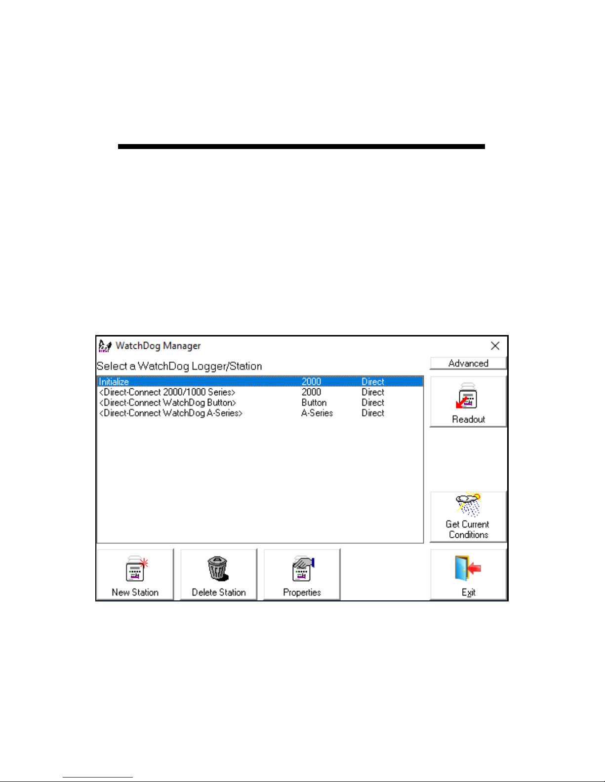
The 2000-Series weather stations can be configured in the
WatchDog Manager screen of SpecWare software (see
SpecWare9 User’s Guide for details). Click new station.
Configuration through the software is necessary to change
the station name, enable/disable Disease Models or set
parameters for the Alarm Output Module. Remember to
identify the WatchDog type as 2000-series.
Configuring the
Weather Station
with SpecWare
Page 14

14
Configuring the
Weather Station
with the Keypad
For the 2000 Series weather stations, SpecWare software
is not necessary to configure the station. The keypad can
be used to select all essential configuration options. Configurable parameters are; sensor type, logging interval,
Degree Day calculation method and latitude and altitude
(model 2900ET only). Configuration through the software
is necessary to change the station name, enable/disable
Disease Models or set parameters for the Alarm Output
Module.
The keypad sequences to set each parameter are as follows.
Setting the Logging Interval
If set for a 30-minute logging interval, the station can hold
183 days of data. Changing the logging interval will also
change the frequency that the station’s memory wraps
around and writes over older data.
5. Use the arrow keys to scroll to the desired port.
6. Press Set. LCD will return to the ‘Current Values’
screen.
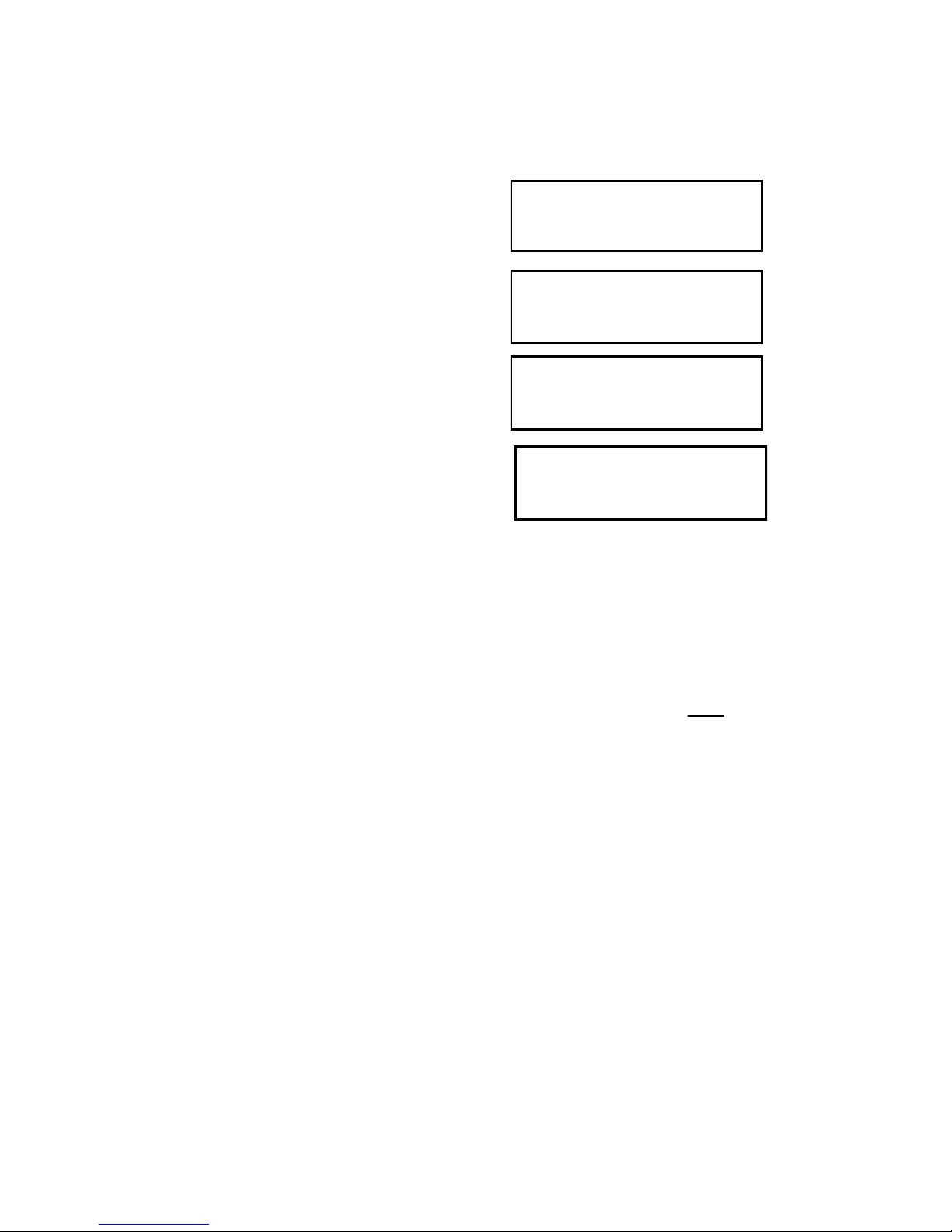
1. Press Display.
2. Press Set.
Select Parameter
To Be Set (↑↓)
4. Press Set.
Set Log Interval
Interval=30 min
3. Use the arrow keys to
scroll to the ‘Log Interval’
option.
SET LOG INTERVAL
Press SET
Page 15

15
6. Press Set to select the port.
7. Use the arrow keys to
Set Port B Sensor
Select Type (↑↓)
sor type. LCD will then return to the ‘Current Values’ screen.
scroll to the desired sensor
type.
8. Press Set to select the sen-
Set Port B Sensor
PAR Light
1. Press Display.
2. Press Set.
Select Parameter
To Be Set (↑↓)
4. Press Set.
Select Port Now
Select Port (↑↓)
3. Use the arrow keys to
scroll to the ‘Sensor Type’
option.
SET SENSOR TYPE
Press SET
5. Use the arrow keys to
scroll to the desired port.
Select Port Now
Port B Press Set
Setting the Sensor Type
Although the keypad can be used to assign a sensor to
an external port, this should only be done when initially
starting the station, re-starting a station whose memory
has been cleared, or for adding a sensor to a previously
unused port. If a port’s sensor assignation is changed
without first downloading the station, all data read from
that port, including historical data read before the change,
will be translated to engineering units as if the new sensor
had always been connected.
Page 16

16
Setting Geographic Data for the ET Report
In addition to temperature, relative humidity, wind speed
and solar radiation data, the Penman-Monteith algorithm
used by the 2900ET statopm uses the station latitude and
altitude to compute reference ET. These are input as follows:
1. Press Display.
2. Press Set.
Select Parameter
To Be Set (↑↓)
4. Press Set.
Set LATITUDE Now
Select LAT (↑↓)
3. Use the arrow keys to
scroll to the ‘ET Values’
option.
SET ET VALUES
Press SET
5. Use the arrow keys to
scroll to the desired
latitude. Take care
that N precedes the
latitude angle if the
station is in the northern hemisphere.
Set LATITUDE Now
LAT=N45o Hit Set
6. Press Set to set the latitude
angle.
Set ALTITUDE Now
Select ALT (↑↓)
8. Press Set to set the altitude. LCD will return to the
‘Current Values’ screen.
7. Use the arrow keys to scroll
to the desired altitude.
Set ALTITUDE Now
ALT=500Feet
Page 17

17
Selecting the Degree Day Calculation Method
The weather station has 2 options for calculating Degree
Days (see Degree Days/Chill Hours, p. 31). The weather
station must measure air temperature for this option to be
available. The desired method is selected as follows:
1. Press Display.
2. Press Set.
Select Parameter
To Be Set (↑↓)
3. Use the arrow keys to
scroll to the ‘DD Calc
Method’ option.
SET DD CALC METHOD
Press SET
7. Press Set to select the method. LCD will return to the
‘Current Values’ screen.
4. The current calculation
will be displayed.
DD TYPE = ACTUAL
Press SET
5. Press Set to make this
option modifiable.
DD TYPE = ******
6. Use the arrow keys to
select the desired
method.
DD TYPE = S SINE
Page 18

18
Other Keypad
Operations
The most common use of the keypad is to view the
weather station’s current sensor readings, calculated parameters, and archived data. Pressing the Display key
once brings the LCD display to life. The screen will initially display descriptive information about the station. The
screen then displays current conditions. Current condi-
tions are refreshed every 20 seconds. Pressing the Dis-
play key a second time will deactivate the display. The
station continues to record data when the display is not
active. To conserve battery power, the display goes off
after 2 minutes of inactivity. The weather station only records the measurements from the sensors. Parameters
calculated and displayed on the LCD by the firmware
(such as Growing Degree Days) are only retained in the
Daily Archive (see Daily Archive, p. 25).
In addition to being able to configure parameters needed
by SpecWare, the keypad is also used to set the date/
time, calibrate the wind vane, reset the running rain counter, configure the radio and select options for parameters
calculated and displayed by the station’s firmware.
The keypad sequences to set each parameter are described on the following pages.
Page 19

19
1. Press Display.
2. Press Set.
Select Parameter
To Be Set (↑↓)
4. Press Set.
09-22-12 11:45AM
Press SET
**-22-12 11:45AM
5. Press Set.
3. Press the down arrow key
once to reach the ‘Time &
Date’ screen.
TIME & DATE
Press SET
6. Enter the month using the arrow keys. Press Set.
7. Enter the day. Press Set.
8. Enter the year. Press Set.
9. Enter the hour. Press Set.
10. Enter the minutes. Press Set.
11. Enter AM or PM. Press Set.
12. LCD will return to the ‘Current Values’ screen.
Setting the Date and Time
It is necessary to use the keypad to set the date and time
for the data being stored in the long-term memory. This is
the only keypad function that is reflected in the logged
data that can’t be handled via a software connection.
Stations sold after January 2012 include a built in clock
with an independent battery. The clock will continue to
keep time when the AA batteries are removed.
Page 20
20
Setting the Display Units
This option determines whether the LCD will show data in
English or metric units.
6. Use the arrow keys to choose whether data is dis-
played in English or metric units.
7. Press Set. LCD will return to the ‘Current Values’
screen.
Note: The unit system used by the 2000-Series Weather
Station can be modified by both the keypad and by
SpecWare. Although it is advisable to have both the software and firmware using the same unit system, it is not
required. SpecWare is equipped to handle situations
where it receives data in a different unit system. However,
if you use SpecWare to change any of the weather sta-
tion’s configuration parameters (i.e. logging interval), the
data logger will also be reconfigured to use the unit system used by SpecWare.
3. Use arrows to scroll to
‘Display Units’.
DISPLAY UNITS
Press SET
1. Press Display.
2. Press Set.
Select Parameter
To Be Set (↑↓)
4. Press Set.
UNITS = English
Press Set
5. Press Set.
UNITS = *******
Press Set
Page 21

21
Setting the Degree Day Counter
The weather station can be programmed to compute Degree Days for a selected base and upper temperature.
This feature is distinct from the Degree Day report in
SpecWare.
4. Press Set.
Counter: DISABLED
BASE=55 UPPER=55
1. Press Display.
2. Press Set.
Select Parameter
To Be Set (↑↓)
3. Scroll to ‘Deg Day Count’
screen.
DEG DAY COUNT
Press SET
6. Use arrow keys to scroll to “StartNow” option. This
will start the degree day counter. The other option is
DISABLED.
7. Press Set.
8. Choose the base temperature using the arrow keys.
9. Press Set.
10. Choose the upper temperature limit using the arrow
keys.
11. Press Set. LCD will return to the ‘Current Values’
screen.
5. Press Set.
Counter: ********
BASE=55 UPPER=55
Caution: Be careful when entering a parameter update
screen for the degree day counter when the counter is
enabled. If the Set key is pressed, the counter status will
become modifiable and the archives WILL BE ERASED.
If this is not desirable, press one of the arrow keys instead of the Set key to exit the screen.
Page 22

22
Caution: Be careful when entering a parameter update
screen for a chill hour counter when that counter is enabled. If the Set key is pressed, the counter status will become modifiable and the archives WILL BE ERASED. If
this is not desirable, press one of the arrow keys instead
of the Set key to exit the screen.
3. Scroll to the ‘Chill Hours’
screen.
CHILL HOURS
Press SET
4. Press Set.
Counter: DISABLED
BASE=55
1. Press Display.
2. Press Set.
Select Parameter
To Be Set (↑↓)
6. Use arrow keys to scroll to “StartNow” option. This
will start the chill hour counter. The other option is
DISABLED.
7. Press Set.
8. Choose base temperature using the arrow keys.
9. Press Set. LCD will return to the ‘Current Values’
screen.
5. Press Set.
Counter: ********
BASE=55
Setting the Chill Hour Counter
The weather station can be programmed to compute Chill
Hours for a selected base temperature. This feature is
distinct from the Chill Hours report in SpecWare.
Page 23

23
1. Press Display.
2. Press Set.
Select Parameter
To Be Set (↑↓)
3. Scroll to the ’Configure
Radio’ screen.
CONFIGURE RADIO
Press SET
5. Press Set again to configure radio.
6. When finished, the screen will go back to Current
Values.
4. Press Set to bring up the
configuration screen.
Press SET Again
To Config Radio
Configuring the Wireless Radio Address
The numerical address of the remote transceiver must be
entered into SpecWare software to facilitate wireless
communication. The weather station can set the address
to be the same as the station’s serial number.
1. Press Display.
2. Press Set.
Select Parameter
To Be Set (↑↓)
3. Scroll to the ‘Set North’
screen.
SET NORTH
Press SET
pointer of the weather vane should be pointed north.
5. Press Set again to complete calibration.
6. When finished, the screen will briefly display
“DONE” then go back to Current Values.
4. Press Set to bring up the
calibration screen. The
Hold Vane North
Press SET Again
Calibrating the Wind Vane
When the weather station is initially placed in the field or
moved, the wind direction must be calibrated. The following procedure will allow you to establish accurate wind
direction readings.
Page 24

24
1. Press Display.
2. Press Set.
Select Parameter
To Be Set (↑↓)
3. Scroll to the ’Reset Rain’
screen.
RESET RAIN
Press SET
5. Press Set again to reset rain counter to zero.
6. When finished, the screen will go back to Current
Values.
4. Press Set to bring up the
configuration screen.
Press SET Again
To Reset Rain
Resetting the Rain Counter
The weather station maintains two rain counters (see
LCD Screens, p. 28); rain since midnight and total accumulated rainfall. The second counter can be reset to zero
at any time. For example, to track weekly rainfall accumulations, the counter could be zeroed every Monday morning.
4. Press Set to reset the disease model.
5. The screen will go back to Current Values and the
disease model will be reset.
1. Press Display.
2. Press Set.
Select Parameter
To Be Set (↑↓)
3. Scroll to the ‘Reset Disease’ screen.
RESET DISEASE
Press SET
Resetting the Disease Models
This option restarts the disease model calculations and
should be done at the beginning of the season.
Page 25

25
The weather station features an archive that allows you to
look at historical data for that location without downloading the data. The archive is regularly updated whenever
the data logger is actively collecting data. The daily archive retains the last 30 days of data. If the battery power
runs low, the station’s firmware will stop measuring and
archiving data until the battery is replaced.
The archive is accessed by pressing the Current/Archive
key. The arrow keys are then
used to scroll to the archived
day of interest. Once a day is
selected, the LCD will cycle
through all the information
stored for that day. This includes high/low temperature,
high/low relative humidity,
total rainfall, the degree day and chill hour counters (if
enabled), and a summary of any active disease models. If
the Degree Day/Chill Hour Counter was not active on a
particular day, the screen will display “No Data” for that
day.
Note: If the Degree Day counter is disabled or reset,
the entire archive for that counter will be erased. Disabling the Degree Day counter does not affect the
storing of data in memory and, thus will not affect
any of the SpecWare report functions.
Daily Archive
DAILY ARCHIVE
Select Day (↑↓)
8/14/12
READING VALUES...
Page 26
26
Battery
Replacement
The 2000 Series weather stations are powered by 4 AA
batteries. This will provide enough power for 1 year of
continuous use with lithium batteries, or 10 months with
alkaline. The battery compartment is accessed by removing the thumbscrews on the upper cover of the WatchDog
(above the LCD). Upon installation of the batteries, the
LCD should illuminate and the logger resume functioning.
The LCD will prompt you to set the date and time (see
Setting the Date and Time, p. 19).
Whenever the battery is replaced, the time and date must
be reset immediately so the data is time-stamped correctly. However, all settings related to Degree Days, Chill
Hours and IPM parameters (disease models, DIF, etc.)
remain stored in the meter’s memory even when the bat-
teries are removed.
Page 27

27
The memory of the 2000-Series weather station is not
automatically cleared when the station is downloaded or
the batteries are replaced. The station can be cleared
manually through SpecWare software. This may be desired if, for example, the station is being shut down for the
season or is being moved to a new location.
Once the command is sent from SpecWare to clear the
memory, the data erasure is carried out automatically by
the logger itself. The PC interface cable can then be disconnected without affecting the process. A data erasure
will take several minutes to complete and the station cannot be contacted in the interim. Once the memory is
cleared, it is impossible to recover. SpecWare provides
warning messages to prevent an accidental clearing of
the memory. See the SpecWare user’s guide for more
details.
Clearing the
Logger’s memory
Page 28

28
The following figures give examples of some of the various
weather station LCD screens. Not all screens will be available on
all models.
-Initial information screen
This is the first screen that appears
when the Display button is pressed.
The first line gives the model number,
version number and serial number. The second line indicates
whether a disease model has been activated. This screen is from
a Model 2700 version 2.0, serial number 10. The apple disease
model enabled. This screen is visible for 2 seconds before proceeding to the date/time/batter screen (below).
-Time, Date, Battery Level
This screen shows the current date,
time and battery strength. The current
date is 09-08-12 and the time is 07:09
PM. The battery is at 90%.
-Rain
This screen shows the current status of both rainfall counters.
The top counter is the amount of rain
since midnight. The lower counter is
the amount of rain since the counter
was last reset (See Resetting Rain
Counter, p. 24).
-Wind
This top line shows the current wind
speed and direction. The second line
shows the high wind speed for the day
and the time it occurred. (See Calibrating the Wind Vane, p. 23).
-Temperature/Wind Chill
This screen shows the current air temperature and wind chill. Note that wind
chill is not defined for air temperatures
greater than 50oF. In that case, wind chill will be the same as air
temperature.
2900 v6.9 SN3971
Codes: P003 B000
LCD Screens
RAIN TODAY 00.15
SINCE RSET 01.23
Wind N 10 MPH
HI 12 MPH 09:45AM
09-08-12 07:09PM
BATTERY AT 90%
Air Temp 36.2oF
Wind Chill 28.9oF
Page 29

29
-Relative Humidity/Dew Point
This screen shows the current relative
humidity as well as the dew point temperature.
-Daily High and Low Values
For temperature and RH, a screen is
available that displays the current high
and low values for the day, along with
the times at which they occurred.
-External Sensor Ports
Data for sensors connected to an external port are displayed with the sensor port on the first line and the sensor
type and measurement on the second line.
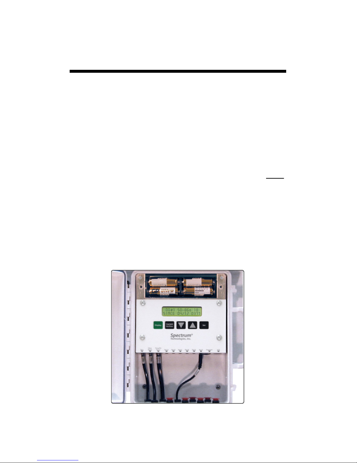
-Degree Day Counter
This screen shows the information for
the Degree Day Counter. This counter
is using a temperature range of 50 to
86°F. So far, it has accumulated 2125 degree days since the
counter was started or reset on July 3. Degree Days calculated
by the station are not saved in downloadable memory.
Note: SpecWare uses stored temperature data to produce its
own Degree Day reports.
-Evapotranspiration
This screen is only available with model 2900ET. It displays two reference
evapotranspiration (ET) values. The
top line is the total reference ET from
the previous calendar day. The bottom line is a value which represents the total amount of ET accumulated in the last 24 hours.
For example, if it is currently Tuesday at 8:00am. The lower line
will give the amount of ET accumulated from 8:00am Monday to
8:00am Tuesday. ET calculated by the meter are not saved in
memory.
Note: SpecWare uses stored weather data to produce its own ET
reports.
HI 74oF 01:58 PM
LO 66oF 03:05 AM
DDay 50-86o
Since 07/12 2125
Air RH 23.6%
Dew Point 36.0oF
Port F:
Solar 225 W/m^2
ET YDAY=0.32 in
ET 24HR= 0.21 in
Page 30

30
Degree Days
Temperature is a key factor contributing to the development of plants,
insects and plant diseases. Degree Days are a way to quantify the
amount of heat that is available, which is a function of the time the temperature is within a given temperature range. For example, if the base
temperature is determined to be 40 degrees and the actual temperature
is 41 degrees for 24 consecutive hours, one Degree Day is said to have
accumulated (41 – 40 = 1 degree for 24 hours or 1 day). Degree Days
indicate the developmental stage of a pest generation. This allows for
more precise pesticide recommendations.
The station’s firmware has two options for calculating Degree Days, the
Actual Degree Day Method and the Single Sine Method.
Actual Degree Day Method
Rather than simply using high and low temperature data for an entire
day, the Actual Degree Day Method integrates the data at smaller time
steps. Degree Day subtotals are calculated at 15 minute intervals to
produce Degree Quarter-Hours (DQH), which are then summed over a
full day. DQH are calculated as follows:
DQH = T
avg
- T
base
Where T
avg
is the average temperature over the 15-minute interval and
T
base
is the base temperature. If the average temperature is greater than
the upper limit of the temperature range, the upper temperature limit is
used instead of the average temperature when calculating DQH. If the
average temperature is less than the base temperature, DQH is set
equal to zero for that interval.
Single Sine Method
The Single Sine Method uses the day’s maximum and minimum temperatures to generate a sine curve. This approximates the pattern of
temperature variation during a typical day. The area between this curve
and the lower threshold temperature represents the accumulated Degree Days for that day.
Chill Hours
Chill hours are calculated as the amount of time spent below a base
temperature. Chill hours accumulations are used to estimate dormancy
for tree fruit.
Degree Days/
Chill Hours
Page 31

31
If rain collector is not reading correctly (or at all)
1. 1. Launch the logger or weather station so you can see the rain
measurements on the LCD (this step is not necessary if the rain collector is attached to a WatchDog 2000 Series Mini or Weather Station).
2. Check the inside of the rain bucket for debris such as leaves that
may be blocking the grid at the bottom of the bucket. Remove the rain
bucket from the base and check for any obstacles (spider webs, debris,
etc.) that may be preventing the tipping spoon from moving freely. If
the hole beneath the grid gets clogged with dirt, the cotter key can be
removed to allow it to be cleared.
3. Manually move the tipping spoon back and forth several times.
Check the LCD after it has updated to see if these tips have been recorded. Do this several times.
4. If the tips are being counted, skip to step 5.
If the LCD is not showing any or all of the manual tips of the spoon, it
may be that the magnetic sensor on the tipping spoon is too far from
the read switch or that the sensor cable is bad. There are 2 cams on
the base of the rain collector that can be rotated to move the tipping
spoon closer to or further away from the read switch. Make this adjustment and check if the LCD shows that the logger can detect manual
tips of the spoon. If so, proceed to step 5. If not, the sensor may need
to be sent in for service.
5. If all the tips are being counted, replace the rain bucket and trickle a
known amount of water into the bucket. 84 ml of water should register
0.1 inches of water (2.5 mm). This is equivalent to 10 tips of the tipping
spoon. The best results are attained when the water is added slowly. It
is recommended that the water be put in a ziplock bag which is then
punctured with a pin to allow the water to slowly enter the rain bucket.
If the reading on the LCD is slightly high or slightly low, the sensor can
be calibrated. When the spoon tips, it lands on screws on either side. If
sensor is reading high, lower the screws. If it is reading low, raise the
screws. It is recommended to adjust the screws a quarter turn and
again run a known amount of water through the bucket to determine if
additional adjustment is necessary.
Rain Collector
Adjustment
Page 32

32
Warranty
This product is warranted to be free from defects in material or workmanship for one year from the date of purchase. During the warranty
period Spectrum will, at its option, either repair or replace products that
prove to be defective. This warranty does not cover damage due to improper installation or use, lightning, negligence, accident, or unauthorized modifications, or to incidental or consequential damages beyond
the Spectrum product. Before returning a failed unit, you must obtain a
Returned Materials Authorization (RMA) from Spectrum. Spectrum is
not responsible for any package that is returned without a valid RMA
number or for the loss of the package by any shipping company.
DECLARATION OF CONFORMITY
Spectrum Technologies, Inc.
3600 Thayer Court
Aurora, IL 60504 USA
Model Numbers: 3350WD2, 3345WD2, 3340WD2, 3330WD2, 3320WD2,
3315WD2
Description: WatchDog Weather Station
Type: Electrical equipment for measurement, control, and laboratory use
Directive: 2004/108/EC
Standards: EN 61326-1:2006
EN 61000-4-2:1995, including A1:1998 and A2:2001
EN 61000-4-3:2002
EN 55011:2007
Michael J. Dunning, Weather Products Manager March 25, 2009
Spectrum Technologies, Inc
3600 Thayer Court
Aurora, IL 60504
(800) 248-8873 or (815) 436-4440
Fax (815) 436-4460
E-Mail: Info@specmeters.com
www.specmeters.com
Rev. 2/2017
 Loading...