

Page 1
SP-UV 200
SP-UV 200 Series UV-Vis Spectrophotometer
Operating Manual
User’s Manual SP-UV 200 1
Spectrum Instruments
Page 2

SPECTRUM INSTRUMENTS AUST PTY LTD.
Add: 1211/ 7, Riverside Quay, South Bank,
Victoria 3006, Australia.
TEL: +61 3 90415554, FAX: +61 3 90415554
Email: info@spectrum-instruments.com.au
General information about Spectrum Instruments Aust Pty Ltd.
on the internet; http://www.spectrum-instruments.com.au
Copyrights and Trademarks
Microsoft, Windows 2000, Windows XP, Windows NT, MS Excel
are registered trademarks of Microsoft Corp.
Edition – September 2013
Technical documentation made by: Spectrum Instruments
This documentation describes the state of this product at the time of
publishing. It needs not necessarily agree with future versions of the
product. Subject to change!
© Copyright 2013 Spectrum Instruments Aust Pty Ltd.
User’s Manual SP-UV 200 2
Spectrum Instruments
Page 3

Content Page
1 Introduction……………………………………………... 4
1.1 Warning and safety labels on SP-UV 200………….…. 4
1.2 Notes on the User's Manual……………………………. 5
2 Safety notes…………………………………………….. 6
3 Disposal…………………………………………….……. 8
4 Performance Specifications…………………….……. 8
5
Design of the SP-UV 200………………………….…….. 9
6 Unpacking instructions……………………….………. 10
6.1 Installation and transport conditions………….……….. 10
6.2 Installation and start-up……………………….………… 10
6.3 Select light source…………………………………….…. 11
6.4 Turn the Lamps on/off……………………………….….. 11
7 Maintenance……………………………………………. 12
7.1 Replacing Halogen lamp………………………….…….. 12
7.2 Replacing Deuterium lamp……………………………... 13
8 Accessories……………………………………………... 15
9 Display and Buttons of SP-UV 200………….………. 17
10 Software function…………………………….………… 18
11 Connect to PC…………………………………………...
24
User’s Manual SP-UV 200 3
Spectrum Instruments
Page 4
1 Introduction
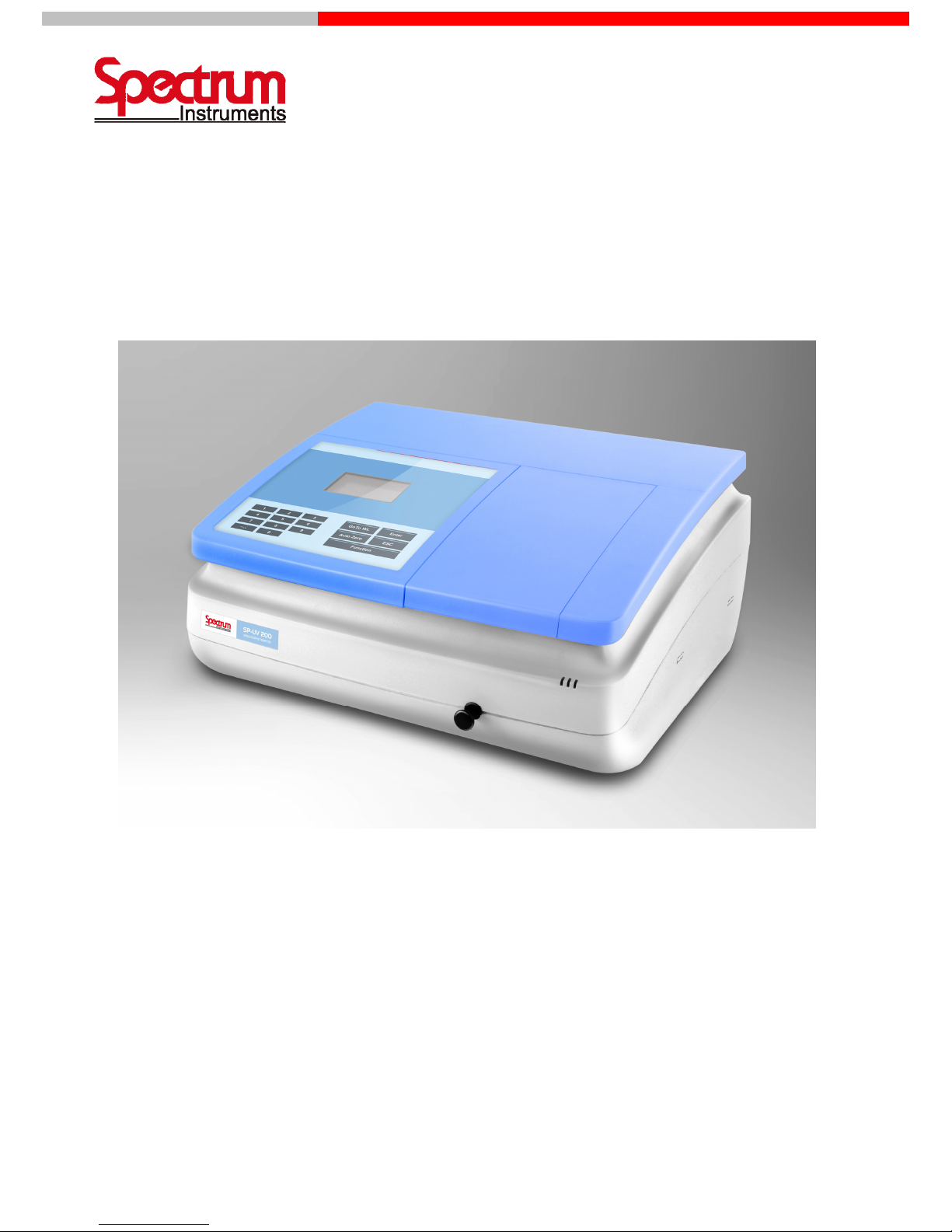
The SP-UV 200 is a single beam spectrophotometer. The instrument is compact, easy-to-use, and
ruggedness. The large sample compartment can accept various accessories and cell from 10mm to 100mm
path length. The built-in RS-232 serial interface enables the instrument to be connected to a printer.
The SP-UV 200 is ideal to use in a clinical laboratory, biochemical laboratory, petrochemical laboratory,
environmental protection and various fields of quality control. This user’s manual provides the description of
the SP-UV 200, a list of main specifications and available accessories.
After carefully unpacking the content, check the materials against the packing list to ensure that you
have received everything in good condition. If some parts are missing, damaged or have any other defects,
please contact you dealer or the sales representative immediately.
1.1 Warning and safety labels on SP-UV 200
The following warning and safety labels are located on the SP-UV 200:
Caution! Hazardous area. Do not remove this cover under any circumstances. Trained
service peoples only. No serviceable components inside. Select the right voltage.
Disconnect the power cable before opening the device cover or replacing fuses!
User’s Manual SP-UV 200 4
Spectrum Instruments
Page 5
1.2 Notes on the User's Manual
In this manual, the following symbols are used to refer you to warnings and notes:
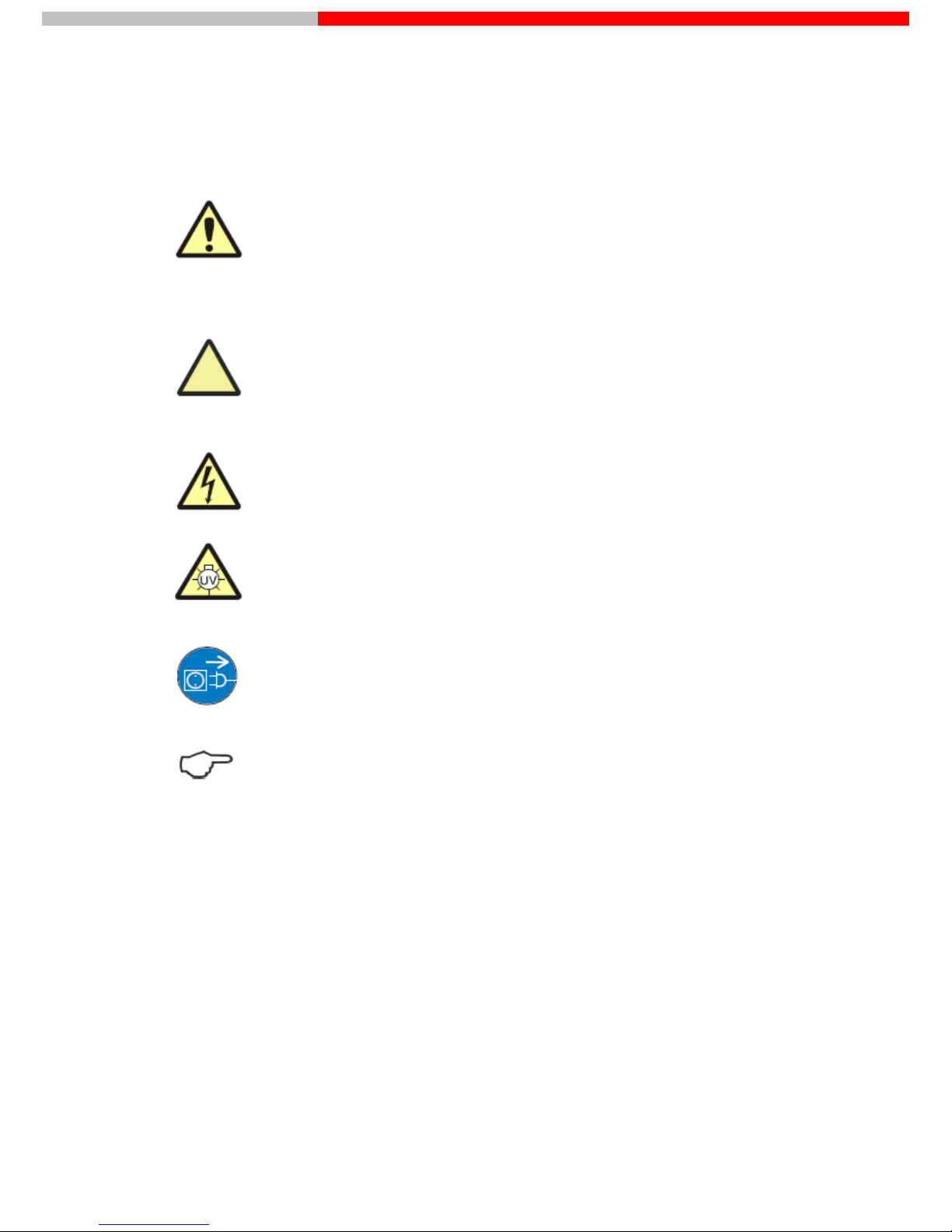
Warning!
Warning messages alert you to a specific procedure or practice which, if not followed correctly, could cause
personal injury.
Caution!
Caution messages refer you to procedures which, if not observed, could result in damage to the equipment.
Caution! Dangerous electric voltage!
Caution! Emission of UV radiation!
Disconnect power cable!
Note
This note must be followed to obtain correct measurement results.
For easier navigation within the manual, the manual uses the following system:
Chapters and illustrations are numbered consecutively.
Every illustration has its own caption.
Steps of operation are numbered.
Cross-references are marked by an arrow (e.g. Notes on the User's Manual p.5)
User’s Manual SP-UV 200 5
Spectrum Instruments
Page 6
2 Safety notes
For your personal safety and for a trouble-free operation, carefully read this chapter before starting up
the SP-UV 200.
Observe all safety notes given in this manual and all messages and notes displayed by the control
software on the screen.
In addition, observe the safety notes for system components of other manufacturers (e.g. PC, printer)
supplied together with the device.
In particular, you should also observe the safety notes given on the labels and the information on the
use, storage and disposal of reagents, reaction cells and the notes on the package inserts of test kits.
Intended use!
The SP-UV 200, including original accessories, may only be used for the applications described in this
manual. The manufacturer cannot assume any liability for any other application, including that of individual
modules or single parts. This also applies to all service or repair work that is not carried out by authorized
service personnel. All warranty claims shall be forfeited.
Local safety regulations!
Observe the local safety regulations relevant to the operation of the device (e.g. labor safety regulations,
regulations for the prevention of and protection against accidents).
References to possible risks given in this manual do not replace the relevant labor safety regulations that
are to be followed.
Personnel!
The SP-UV 200 may only be operated by appropriately qualified and trained personnel.
For that, the knowledge of the information provided by this manual is indispensable and taken for granted.
Emergency stop!
In the case of emergency, disconnect the SP-UV 200and its components from line power by removing the
power plug from the power outlet.
Caution! This procedure involves the risk of data loss and damage to the operating system!
Electric shocks!
The SP-UV 200 is electrically powered. At several parts inside the system, extremely hazardous electrical
voltages are accessible!
User’s Manual SP-UV 200 6
Spectrum Instruments
Page 7
To ensure Protection Class I (protective earth connectio
n) of the device, connect the power plug of the
device only to a power outlet with protective earth conductor. The protective effect must not be undone by
the use of an extension cable without protective earth conductor.
Before opening the device or removing any device covers, disconnect the power cable!
Before connecting the SP-UV 200 to the power outlet, make sure the line voltage supplied agrees with the
operating voltage specified on the rating plate at the rear panel of the device. Operation of the device with
any other operating voltage than that specified may result in the destruction of the device.
Only use fuses of the specified type.
Do not operate the device in explosion-risk rooms!
UV radiation!
Never look directly or indirectly, e.g. via a mirror, into the radiation emitted by the lamp
to avoid the risk of getting conjunctivitis!
Therefore, switch off the lamp for lamp replacement!
Lamp damage!
Do not grasp functioning halogen and deuterium lamps on their glass bulbs.
Contamination on the bulb affects the radiation properties of the lamps.
Especially protect the beam-exit window of the deuterium lamp.
Accumulation of heat
Heat accumulation might result in overheating and faults on the device.
Make sure not to cover the ventilation slots of the SP-UV 200!
Before you switch on the SP-UV 200, remove its dust cover!
Handling liquids
Take care to ensure that no liquids can enter the SP-UV 200 to avoid any damage to the device.
Risk of corrosion
Do not set up the device in the vicinity of aggressive vapors, e.g. strongly corrosive acid or caustic vapors!
The vapors might corrode the connections, mechanical and optical components of the device.
Avoid exposing the sample compartment to strongly corrosive substances! For the analysis of such samples,
User’s Manual SP-UV 200 7
Spectrum Instruments
Page 8
use vapor-tight stoppered cells.
After the measureme
nt, do not leave the samples unnecessarily long in the sample compartment of the
device!
3 Disposal
The owner/operator of the SP-UV 200 must ensure to dispose of the waste material (samples) cropping up
in the analyses in accordance with the relevant legal and local regulations.
When the service life of the device is over, dispose of the device with its electronic components as electronic
scrap observing the relevant regulations.
4 Performance Specifications
Model SP-UV 200 SP-VIS 200
Optic system 1200 grooves/mm diffraction
grating monochromator.
1200 grooves/mm diffraction
grating monochromator.
Optic type Single beam Single beam
Light path 10mm-100mm 10mm-100mm
Spectrum band width 2nm 4nm
Wavelength range 190-1100nm(0.1nm increment) 320-1100nm(0.1nm increment)
Wavelength accuracy ±0.5nm ±0.5nm
Wavelength repeatability ±0.3nm ±0.3nm
Stray light ≤0.05%T (at 220nm NaI& 340nm,
NaNO
2
)
≤0.3%T (at 360nm, NaNO
2
)
Photometric mode T, A and Conc. measurement T, A and Conc. measurement
Photometric range 0-125.0%T, -1.0-1.000A,
0.000-9,999 Conc.
0-125.0%T, -1.0-4.000A,
0.000-9,999 Conc.
Photometric accuracy ±0.3%T ±0.3%T
Photometric repeatability ±0.2%T ±0.2%T
Baseline stability ±0.002A/hr(@500nm, after lamp
turn on for 1 hour)
±0.002A/hr(@500nm, after lamp
turn on for 1 hour)
Baseline flatness ±0.002A ±0.003A
Noise level ≤0.001A(at 0A, 500nm) ≤0.001A(at 0A, 500nm)
Light source Tungsten-Halogen & Deuterium Tungsten-Halogen
Detector Silicon Photodiode Silicon Photodiode
User’s Manual SP-UV 200 8
Spectrum Instruments
Page 9

5 Design of the SP-UV 200
Front side
Fig. 1Front side of SP-UV 200
Back side
Fig. 2Back side of SP-UV 200
User’s Manual SP-UV 200 9
Spectrum Instruments
Page 10

6 Unpacking instructions
6.1 Installation and transport conditions
Installation conditions
Considering the dimensions of the SP-UV 200 and a clearance of approximately 100mmto the sides and the
front, the device needs a bench space of at least 665 x 565 mm.
Caution!
Do not cover the ventilation slots of the device!
Do not place any objects on the device!
Do not operate the device in explosion-risk rooms!
Keep aggressive vapors, e.g. strongly corrosive acid or caustic vapors away from the vicinity of the device.
The installation site of the SP-UV 200 must meet the following requirements:
The place should be free of draft, dust, corrosive vapors as well as vibrations.
Do not set up the SP-UV 200near electromagnetic fields (e.g. of motors).
Avoid dripping or splashing water near the instrument.
Do not expose the device to direct sunlight or the radiation of heaters.
Temperature range: + 15 ... + 35 °C
Humidity: up to 85 % (at + 30 °C)
Conditions for storage and transport
For transport and storage, the following ambient conditions must be complied with:
Temperature range in transport: -40...+70 °C
Relative humidity in transport: up to 95 %
6.2 Installation and start-up
Observe correct position of device!
Move the SP-UV 200 only in upright position (observe label on transport case).
Do not turn the device upside down.
Electric shock
Before connecting the SP-UV 200and the PC to line power, make sure the available line voltage agrees with
the operating voltage specified on the type labels. Operation of the devices on line voltages other than the
specified operating voltage may result in their destruction.
User’s Manual SP-UV 200 10
Spectrum Instruments
Page 11

1. Unpack the contents carefully and check the materials.
2. Place the i
nstruments in suitable location.
3. Remove any obstructions or materials that could hinder the flow of air under and around the instrument
vibration.
4. Select the right voltage.
5. Plug the power cord into an outlet. Turn on the instrument and allow it to warm up for 20 minutes before
taking any readings. A self-test starts automatically.
Your spectrophotometer is now ready for operation.
6.3 Select light source
You can select light source switch point between 325nm to 355nm.
1. Press [Function]. (Press again, if necessary, to display lamp Exchange menu item).
2. Press [4], to select lamp Exchange menu item. Press [Enter].
3. Use [0] ~ [9] to set light source switch point. Press [Enter].
6.4 Turn the Lamps on/off
You can turn off halogen lamp or the deuterium lamp, when your methods do not need it.
1. Press [Function]. (Press again, if necessary, to display Lamp on/off menu item).
2. Press [5], to select Lamp on/off menu item. Press [Enter].
3. Press [1], to turn on tungsten lamp. Press [2], to turn off tungsten lamp. Press [3], to turn on
deuterium lamp. Press [4], to turn off deuterium.
User’s Manual SP-UV 200 11
Spectrum Instruments
Page 12

7 Maintenance
This SP-UV 200 spectrophotometer has been designed to be durable and reliable.
Therefore, the routine maintenance of the instrument is minimal.
However, you will need to replace the lamp or you may want check the wavelength calibration and
photometric linearity to verify the instrument’s performance.
The manufacturer recommends only authorized service representatives to perform
procedures requiring removal of the instrument’s cover and replacement of electrical components. To
protect both of yourself and your instrument, be sure to contact the authorized service representative to
perform any service procedure, when you do not feel comfortable performing.
7.1 Replacing Halogen lamp
Electric shock!
Before changing the halogen lamp, make sure to switch the device off with the power switch.
Caution: Risk of burns!
Allow the halogen lamp to cool down to avoid the risk of burns!
Caution: Eye injury!
Never look into the lighting lamp as the radiation may cause eye injury!
Caution!
Do not touch the glass bulb of the lamp to avoid any contamination affecting its performance!
1. Turn the power off and unplug the instrument.
2. Put all samples and not fixed elements out of the sample compartment.
3. Place the SP-UV 200 carefully on a soft underlay on the top side of the device so that you can access the
underside.
Fig. 3 Lamp house cover on the underside of SP-UV 200
User’s Manual SP-UV 200 12
Spectrum Instruments
Page 13

4.
Remove the two screws (11) and the lamp house cover (12) on the underside of the instrument.
Fig. 4 Lamp compartment of SP-UV 200, opened
5. Unscrew the holder of the halogen lamp (13) and take the holder with the halogen lamp out of the
device.
Fig. 5 SP-UV 200holder of the halogen lamp
6. Remover the lamp (14) from lamp holder
7. Replace the new lamp carefully in the holder.
Caution
Do not handle Halogen lamp with bare fingers. Use a piece of tissue or cloth when handling the lamp. The
oil from your fingers can cause the lamp to burn out prematurely!
8. Replace and fix the holder with the new halogen lamp in the device
9. Close the cover of the lamp house using the 2 screws.
10. Replace the device with the top side on top.
7.2 Replacing Deuterium lamp
Risk of electric shock!
Before changing the deuterium lamp, make sure to switch the device off with the power switch.
Caution: Risk of burns!
Allow the deuterium lamp to cool down to avoid the risk of burns!
User’s Manual SP-UV 200 13
Spectrum Instruments
Page 14

Emitted UV radiation!
Never look directly or indirectly, e.g. via a mirror, into the radiation emitted by the lamp to avoid the risk of
getting conjunctivitis!
Dirt on beam exit window!
Do not touch the glass bulb of the new deuterium lamp. Particularly avoid contamination on the quartz glass
beam exit window! If you touched the glass bulb with your fingers, wipe the fingerprints off with a clean, lint
free cloth and pure alcohol.
The performance of the lamp will deteriorate by contamination.
1. Turn off the power and unplug the instrument
2. Put all samples and not fixed elements out of the sample compartment
3. Place the SP-UV 200 carefully on a soft underlay on the top side of the device so that you can access the
underside
4. Remove the two screws (11) and the lamp house cover (12) on the underside of the instrument
5. Unscrew the 2 screws of the deuterium lamp (13), disconnect the electronic plug connection and take the
deuterium lamp out of the device
Do not handle Deuterium lamp with bare fingers. Use a piece of tissue or cloth when
handling the lamp. The oil from your fingers can cause the lamp to burn out prematurely!
6. Replace the new deuterium lamp and fix it with the screw
7. Close the cover of the lamp house using the 2 screws.
8. Replace the device with the top side on top.
User’s Manual SP-UV 200 14
Spectrum Instruments
Page 15

8 Accessories
For the installation of accessory use the two screws on the bottom of the sample compartment.
8.1 Manual 4 cell changer
The standard configuration is a 4 cell changer for 1 cm cells. There is also 4 cell changer for 5 and 10 cm
cell available. As an option there are also 4 cell changer for cells with 50 and 100 mm path length available.
Fig. 6 Manual 4 cell changer
Use the cell selector armasacattl of the manual cell changer to set the position of the manual cell changer.
Fig. 7 Positions of the 4 cell changer
8.2 Adjustable cell holder
Micro cells and ultra-micro cells have the standard outside width of 12.5 mm, but a reduced inside width or
filling aperture of 1 to 4 mm. This requires accurate alignment of the cell in the light beam.
This adjustable cell holder can be used for cells with an aperture high of 8.5 mm.
Fig. 8SP-UV 200 adjustable cell holder
Insert the adjustable cell holder in the sample compartment with screw 1 to the back site. Use the screw 1 to
adjust the cell horizontal to the light beam and screw 2 to adjust the cell vertical to the light beam. The cell
has the optimal position if the high transmittance is reached.
User’s Manual SP-UV 200 15
Spectrum Instruments
Page 16

8.3 Round cell holder
This special cell holder can be used for round cell of standard test kits. Cells with a diameter up to 16 mm
and a high up to 11 cm can be used.
Fig. 9SP-UV 200 Round cell holder
8.4 Automatic cell changer
The automatic cell changer accommodates 6 cells a 10mm path length cell of 12.5 x12.5 x 45 (L x W x H in
mm).
Fig.10 Automatic 6 cell changer
To install this accessory in the sample compartment of the SP-UV 200 switch the device off, plug the
electrical connection in the internal serial port at the back site of the sample compartment. Use two screws
to install the system. Start the instrument new.
8.5 Printer
To install the printer to the SP-UV 200 switch the device off, plug the electrical connections into the USB at
the back side of the device. Start the instrument new.
User’s Manual SP-UV 200 16
Spectrum Instruments
Page 17

9 Display and Buttons of SP-UV 200
Fig. 11 Display and buttons
Display
The display shows details of what is currently happening in the spectrometer and
allows you to make changes to make changes to parameters as necessary.
keypad
All of the parameters required to operate the SP-UV 200 can be entered through the
spectrometer’s keypad. Normally, however, most of these parameters are controlled
using an attached data system, such as Shanghai Spectrum’s Win-SP software.
When a Shanghai Spectrum data system is controlling your SP-UV 200, it is possible for
the data system to disable editing of the spectrometer’s current method from the
keypad.
User’s Manual SP-UV 200 17
Spectrum Instruments
Page 18

10 Software function
10.1 Function
Press[Function] to call menu.
1. Abs/%T/Conc. Absorbance/Transmittance/Concentration measurement
2. 0%T Dark Currency Correction
3. Factor/Conc. Concentration factor edit
4. Lamp Exchange Set light source switch point
5. Lamp on/off Turn off light source
6. Standard Curve Create a standard curve
7. Language Select display language.
8. Com. with PC Connect with PC
9. Set time Set the date and time
10.2 Select Language Mode
1. Press [Function]. (Press again, if necessary, to display Language menu item). The LCD will
display as blow.
2. Press [7], to select Language menu item. Press [Enter].The LCD will display as blow.
3. For Chinese press [1], for English press [2], for German press [3]
10.3 Turn the Lamps on/off
You can turn off halogen lamp or the deuterium lamp, when your methods do not need it.
1. Press [Function]. (Press again, if necessary, to display Lamp on/off menu item).The LCD will
display as blow.
5.Lamp on/off
6.Standard Curve
7.Language
8.Com. With PC
Select Language:
1.Chinese
2.English
3.German
5.Lamp on/off
6.Standard Curve
7.Language
8.Com. With PC
User’s Manual SP-UV 200 18
Spectrum Instruments
Page 19

2. Press [5], to select Lamp on/off menu item. Press [Enter].The LCD will display as blow.
4.UV
lamp off
1.VIS lamp on
2.VIS lamp off
3.UV lamp on
3. Pr
ess [1], to turn on tungsten lamp. Press [2], to turn off tungsten lamp. Press [3], to turn on
deuterium lamp. Press [4], to turn off deuterium lamp.
10.4 Absorbance / Transmittance / Concentration Measurement
1. Press [GoTo WL], select wavelength.
2. Press [Function]. (Press again, if necessary, to display Abs/%T/Conc. menu item).The LCD will
display as blow.
3. Press [1], to select Abs/%T/Conc. menu item. Press [Enter].The LCD will display as blow.
1.Abs
2.Tra n
3.Conc
1.Abs/%T/Conc
2.0%T
3.Factor/Conc
4.Lamp Exchange
4. Me
asurement
Absorbance/Transmittance Measurement
1) Press [1], to select Abs menu item. The LCD will display as blow.
546.0 nm ABS
2) Place the
cell with blank solution in the blank position (position 1) of the cell
holder.
3) Place the samples or standard solution in the other positions of the cell holder.
4) Close the sample compartment cover. Pull the cell holder’s rod with the blank
sample in the measurement beam. Measure the blank value by pressing the
[Auto Zero] until display shows “100.0%T” or 0.000Abs.
5) Pull the cell holder’s rod to the next sample position and read the %T or Abs
value of the samples.
Note
Pay attention that second step of the cell changer is only for reading 0%T. There
are two steps between Position 1 and 2 of the manual cell changer.
Alternatively, if you use a single cell holder, at first put the blank solution in the
light beam and set the value to 100%T or 0Abs by pressing the [Auto Zero]. Then
put the sample or standard cell in the cell holder
User’s Manual SP-UV 200 19
Spectrum Instruments
Page 20

6) When the printer is connected, you can print out the result by pressing [P/C].
Note
Choose cells with the same path length for all blanks, standards and samples of
the analytical method you are using.
For measurements below 325 nm, use quartz cells. Glass or plastic cells are only
usable above 325 nm.
The liquid level must be at least 20 mm in a standard square cell.
10.5 Concentration mode
10.5.1 Determination of the concentration via one point
calibration
The results are calculated with the following equations:
CONC = ABS * CONC
Standard
/ ABS
Standard
1. Press [GoTo WL], select wavelength.
2. Place the blank solution in the sample compartment and close the sample compartment
cover.
3. Press [Auto Zero] to measure the blank solution.
4. Remove the blank solution from the sample compartment.
5. Press [Function]. (Press again, if necessary, to display Factor/Conc menu item). The LCD will
display as blow.
6. Press [3] to select Factor/Conc. menu item. Press [Enter].The LCD will display as blow.
7. Press [2] to select Std. Conc. menu item. Press [Enter]. The LCD will display as blow.
Input
Std. Conc 1.00
1.Std. FACT
2.Std. Conc
1.Abs/%T/Conc
2.0%T
3.Factor/Conc
4.Lamp Exchange
8. Insert the standard solution into the cell holder or cell changer. Close the sample
compartment cover.
9. Use digital key to enter the concentration of the standard, press [Enter].
10. Insert the sample solution into the cell holder or cell changer. Close the sample
compartment cover.
User’s Manual SP-UV 200 20
Spectrum Instruments
Page 21

11. Read the results directly in concentration units on the digital display.
10.5.2 Determination of the concentration via factor
The results are calculated with the following equations:
CONC = ABS * FACTOR
1. Press [GoTo WL], select wavelength.
2. Place the blank solution in the sample compartment and close the sample compartment
cover.
3. Press [Auto Zero] to measure the blank solution.
4. Remove the blank solution from the sample compartment.
5.Press [Function]. (Press again, if necessary, to display Fact/Conc menu item). The LCD will
display as blow.
6. Press [3] to select Factor/Conc. menu item. Press [Enter]. The LCD will display as blow.
7. Press [1] to select Std. FACT menu item. Press [Enter]. The LCD will display as blow.
Input
Std. FACT 1.00
1.Std. FACT
2.Std. Conc
1.Abs/%T/Conc
2.0%T
3.Factor/Conc
4.Lamp Exchange
8. U
se digital key to enter the factor of the standard, press [Enter].
9. Insert the sample solution into the cell holder or cell changer. Close the sample
compartment cover:
10.Read the results directly in concentration units on the digital display.
10.5.3 Determination of the concentration via calibration curve
The results are calculated with the following equations:
CONC = ABS * B + K
1. Place the blank solution in the sample compartment and close the sample compartment cover.
2. Press the [Auto Zero] button to zero the blank solution.
3. Remove the blank solution from the sample compartment.
4. Press [Function]. (Press again, if necessary, to display Standard Curve menu item).The LCD will
display as blow.
User’s Manual SP-UV 200 21
Spectrum Instruments
Page 22

5.Press [6] to select Standard Curve menu item. Press [Enter].The LCD will display as blow.
6.Press [1] to select Create Curve menu item. Press [Enter].The LCD will display as blow.
7.Press [1] to select No. of samples menu item. Press [Enter].The LCD will display as blow.
Input
Sample Num:
1.No. of Samples
2.Unit
3.Input Conc
4.Test Sampl e
1.Create Curve
2.Load Curve
3.Delete Curve
4.Print Curve
5.Lamp on/off
6.Standard Curve
7.Language
8.Com. With PC
8. Use digital key to enter samples number, press [Enter].
9. Press [2] to select Unit menu item. Press [Enter].The LCD will display as blow.
10.
Use digital key to enter sample unit, press [Enter].
11. Press [3] to select Input Conc menu item. Press [Enter].The LCD will display as blow.
Input
Conc:
Number:1
1.mg/L
2.ug/L
3.ng/kg
4.ug/kg
12. Use digital key to enter sample concentration, press [Enter].
13. Press [4] to select Test Sample menu item. Press [Enter].The LCD will display as blow.
Number: 1
Conc: 1.00
Abs.:
14.Insert the standard solutions in the light beam. Press [Enter].
User’s Manual SP-UV 200 22
Spectrum Instruments
Page 23

If all standards are measured, you get the co
efficient of the calibration K and B as well as the coefficient of
determination R.
10.5.4 Use an existing calibration curve
1. Press [Function]. (Press again, if necessary, to display Standard Curve menu item).The LCD will
display as blow.
2. Press [6] to select Standard Curve menu item. Press [Enter]. The LCD will display as blow.
3. Press [2] to select Load Curve menu item. Press [Enter]. The LCD will display as blow.
4. Use digital key to load curve stored in spectrometer, press [Enter].
10.5.5 Delete an existing calibration curve
1. Press [Function]. (Press again, if necessary, to display Standard Curve menu item).The LCD will
display as blow.
5.Lamp on/off
6.Standard Curve
7.Language
8.Com. With PC
Curve No.:
1.Create Curve
2.Load Curve
3.Delete Curve
4.Print Curve
5.Lamp on/off
6.Standard Curve
8.Com. With PC
7.Language
2. Press [6] to select Standard Curve menu item. Press [Enter]. The LCD will display as blow.
3. Press [3] to select Delete Curve menu item. Press [Enter]. The LCD will display as blow.
Curve No.:
1.Create Curve
2.Load Curve
3.Delete Curve
4.Print Curve
4. Use digital key to delete curve stored in spectrometer, press [Enter].
User’s Manual SP-UV 200 23
Spectrum Instruments
Page 24

10.6 Set time
1. Press [Function]. (Press again, if necessary, to display Set time menu item). The LCD will display as
below.
9.Set Time
2. Pr
ess [9], to select Set time menu item. Press [Enter].The LCD will display as blow.
Set Time:
Date:
Time:
3. F
or example: The data is 2014/01/10, time is 16:20:10, you can input 14.01.10. After that the
symbol () move to [Time:], then input 16.20.10 and press [Enter]. The LCD will display the date
and time about 10 seconds and change automatically to the main page.
10.7 Select Lamp Exchange
1. Press [Function]. (Press again, if necessary, to display Lamp Exchange menu item). The LCD will
display as below.
1.Abs/%T/Conc
2.0%T
3.Factor/Conc
4.Lamp Exchange
2. Pr
ess [4], to select Lamp Exchange menu item. Press [Enter].The LCD will display as blow.
Select Lamp
Exchange:
3. U
se digital key to enter the wavelength of lamp exchange, press [Enter].
11. Connect to PC
You can connect to a personnel computer (PC) when you need to control the system by PC
control.
1. Press [Function]. (Press again, if necessary, to display Com. With PC menu item).The LCD will
display as blow.
User’s Manual SP-UV 200 24
Spectrum Instruments
Page 25

2. Press [8], to select Com. With PC menu item. Press [Enter].The LCD will display as blow.
Com. with PC:
1.RS232
2.USB
5.Lamp on/off
6.Standard Curve
7.Language
8.Com. With PC
3. Pr
ess [1], to use RS232 connect with PC. Press [2], to use USB connect with PC.
User’s Manual SP-UV 200 25
Spectrum Instruments
Page 26

User’s Manual SP-UV 200 26
Spectrum Instruments
SPECTRUM INSTRUMENTS AUST PTY LTD.
Add: 1211/ 7, Riverside Quay, South Bank,
Victoria 3006, Australia.
TEL: +61 3 90415554, FAX: +61 3 90415554
Email: info@spectrum-instruments.com.au
http://www.spectrum-instruments.com.au
 Loading...