

Spectrum SoftH2O DUO 30, SoftH2O DUO 50, SoftH2O DUO 75, SoftH2O DUO 150, SoftH2O DUO 100 Installation, Service & Operation Manual
...Page 1
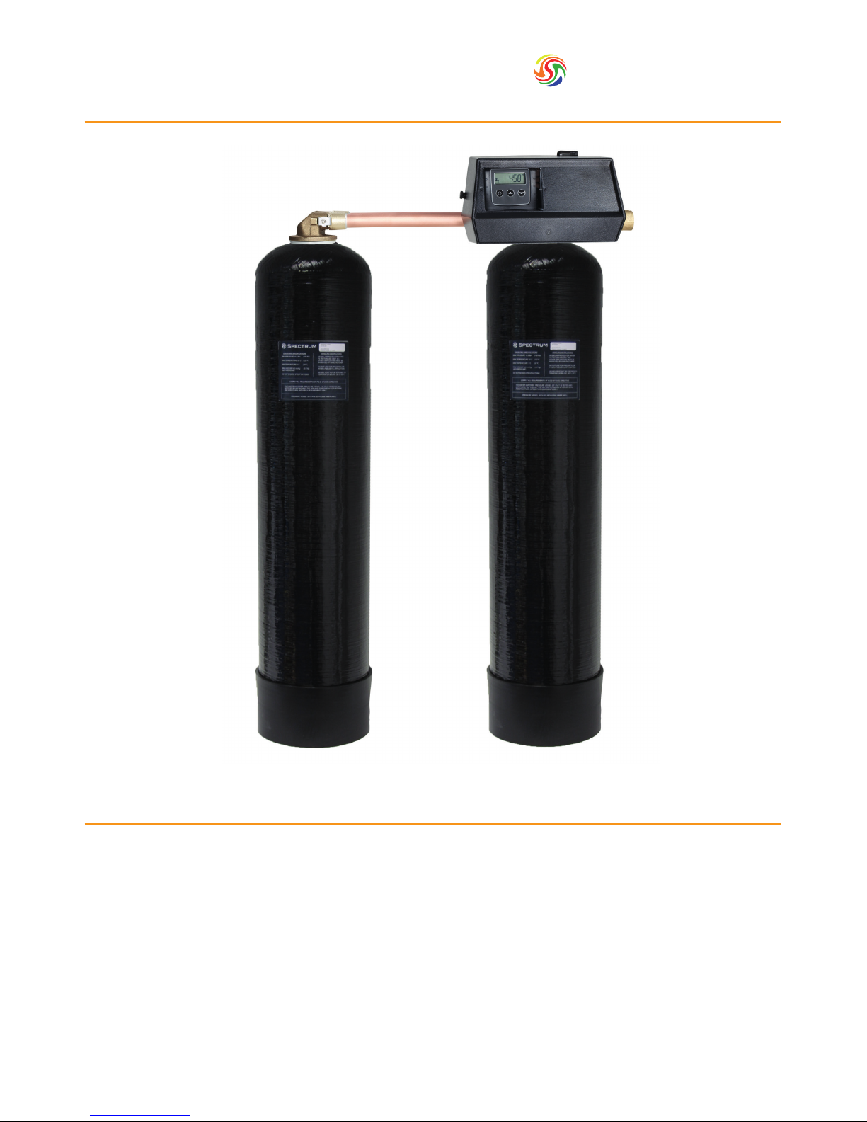
Table of Contents
1. General Notes p.2
2. Description & Equipment Adjustments p.3
3. Components, Features & Functions p.4
4. Valve User Interface p.5
5. Installation Instructions p.6
6. Assembly & Start-Up p.7
7. Programming & Operation p.9
8. Master Programming Mode p.11
9. User Programming Mode p.16
10. Diagnostic Programming Mode p.17
11. Programming Charts p.18
12. Troubleshooting p.19
13. Cautions p.21
14. Technical Information p.22
Installation, Service &
Operation Manual
SoftH2O DUO
Spectrum
TM
Water Softener
Page 2

Spectrum
TM
2
1. General Notes
The SoftH2O-DUO water softeners are a range that utilise two resin pressure vessels. Compared to standard single
pressure vessel water softeners, this setup guarantees 24/7 access to soft water. Whilst one pressure vessel is in service,
the other one is either in standby or in regeneration. The automatic valve monitors the amount of water going through
the softener and triggers regeneration when the softening capacity of one pressure vessel expires. This manual is for a
range of softeners based on the eck 9000/9100/9500 with various volumes of resin going from 30 to 350 litres.
Please take a look at the model supplied as this will have an inuence on various parameters for starting up your
softener, especially during programming. Once installed softeners are low in maintenance and only require a top up of
salt in order to operate properly. Please ensure that the brine tank has got a minimum level of salt at all times. Although
the original valve manual is included, it is preferable to use this O.E.M. manual as all settings and information will be
adapted to the conguration of your specic system.
Page 3

3
Spectrum
TM
Regeneration Mode
Regeneration Type
Electrical Supply
Installation Number Nominal Capacity
m3 °tH
Valve Serial Number Inlet Water Hardness
°tH
Tank Size Treated Water Volume
litres
Resin Type Outlet Water Hardness
°tH
Resin Volume
litres
Salt Quantity per Regeneration
kg
Chronometric
days
Down Flow Brining
1) Backwash
min
2) Brining & Rinse
min
3) Rapid Rinse
min
4) Brine Tank Rell
min
Low Voltage DC Transformer
2. Description &
Equipment Adjustments
Page 4

Spectrum
TM
4
3. Components, Features
& Functions
Component Features Functions
Automatic
Control Valve
• FDA approved Noryl plastic
• Strong corrosion resistance
• Innovative design
• 24 hours control and monitoring with a timer; automatically
regenerates the media bed at the system’s set time of
regeneration according to the set regeneration frequency.
• Automatically calculates a cycle plan according to the quality
of supply water and the user’s actual water use.
• Cycle Process:
In service: Once the water is supplied with correct pressure
and ow, the cations contained in hard water will be replaced
by Na
+
in regenerants, then the softening system will supply
softened water through its outlet.
Backwash: When the ion exchange resin has been
exhausted, the resin bed needs to be regenerated. Before
the regeneration of the resin bed, a backwash step is
necessary for two main purposes; removing the residue
in the resin bed and loosening the impacted resin bed for
better regeneration efciency.
Rinse: Rinse the resin bed to remove the residual regenerant
(salt) after the brining step until the water from outlet
contains no regenerant; rinse could also compact the resin
bed for a better softening effect.
Rell: Rell the brine tank with water to dissolve salt for the
next regeneration.
Valve Operation Mode Softener: Duplex water softener operation
Regeneration Mode Volumetric immediate with electronic timer
Outlet water hardness can be adjusted
User can adjust the mixing valve to get desired outlet water
hardness
Display Format Metric
Media High-grade Anion exchange resin Food grade softening resin
Pressure
Vessel
• NSF 44 tested and certied
• Polyethene material manufactured for the
Food & Beverage industries
• Light, high pressure resistance
• Strong corrosion resistance
Pressure vessel holds the resin and a distribution system
Riser Tube &
Distribution
System
A riser tube and distribution system disperse water evenly
through the resin bed
Brine Valve
& Tank
• High pressure resistance
• Brine valve prevents the brine tank from overowing
• Water and salt mix in the brine tank. Salt will dissolve
continuously until the water is saturated by salts
Page 5
5
Spectrum
TM
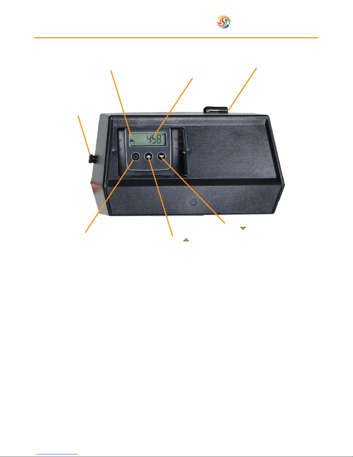
4. Valve User Interface
Down Button ( )
Up Button ( )
Extra Cycle Button
Cover Unlocking Nut
Service Icon
Time/Data Display
Drain Line
Page 6

Spectrum
TM
6
5. Installation Instructions
Water Pressure 2 - 8 bar
Electrical Supply Uninterrupted AC
Existing Plumbing Free of any deposits or build-ups inside pipes
Softener Location Locate close to drain & connect according to plumbing codes
Bypass Valves Always provide external bypass valve
The DUO water softener should be
installed and prepared by a qualied
person.
The system should be ready to use
after the complete installation and a
regeneration test. Any other operations
are not necessary unless power supply is
cut off accidentally.
• The softener needs to be installed onto the mains water supply. Piping has to comply with the regulations of the
country where it is installed.
• The softener will require space for maintenance and operation. Please allow enough room on the top to remove the
valve should it be needed. Also ensure access to the valve is clear in order to be able to visualise or adjust settings
on the electronic board.
• The softener should be installed on a dry at surface.
• The softener uses mains power 230-240V AC 50Hz which is transformed into 24V DC. Please ensure that the electrical
supply is protected from water or extreme conditions. All electrical installations have to comply with laws of the
country in which it is installed.
• The water needs to have a pressure between 2-8 bar and 4-42 degrees Celsius.
• For residential purposes, it is essential to ensure that at least one drinking water tap is not connected to the softener.
Softened water has a high Sodium content which is to be avoided for people on low sodium or salt diets, babies on
infant formulas.
5.1. Connecting
1. Two drain connections will be required. The rst drain should be connected directly to the valve. (For
the 9000/9100 a ½”hose, for 9500 a ¾” BSP). The diameter of the exible drain hose should be able to
accommodate the ow of water to the drain.
N.B. if the water cannot ow to the drain properly, the performance of the softening system will be affected.
The drain should never be connected at a point higher than the softener as the back pressure will again affect
ow.
2. The second drain should be connected to the brine tank over ow elbow. This is in place to ensure that if for
any reason the brine tank should overll the excess is sent to the drain. The diameter of the exible hose should
be able to accommodate the ow and the outlet should not be connected above the height of the system.
N.B. the softening system should be connected with an external bypass in order to allow the system to be
taken ofine without affecting water supply elsewhere.
N.B. any joint work or metal work should be completed prior to installation of the softening system.
Flexible hose
Control Valve
Inlet
Outlet
Watermeter
Drain
Flexible hose
Copper pipe
Control Valve
Salt suction lling
Inlet
Outlet
Watermeter
Copper pipe
Drain
Pressure
Vessel 1
Pressure
Vessel 2
Pressure
Vessel 1
Pressure
Vessel 2
Brine Tank
Salt suction lling
Brine Tank
Water Softener Plumbing Overview
Drain
Connection
Page 7
7
Spectrum
TM
6. Assembly & Start-Up
6.1. Assembly
1. Place the riser tube inside the rst pressure vessel. Depending on the size of the vessel, the system will either be
supplied in a classic cone shape con guration or, for larger vessels, a star-type distribution system. Assemble the
star type distribution system if applicable.
2. Centre the distribution system inside the vessel and seal the top of the riser tube to ensure that no resin enters
the distribution system.
3. Fill the vessel (up to 85%) with the softening resin, ensuring that the distribution system remains upright and
central.
N.B. a funnel is recommended to aid the lling process and prevent excess resin from being spilt.
CAUTION: Resin can present a serious slip hazard if excessive amounts are spilt.
4. Lubricate the internal valve O-ring with 100% silicon lubricant and screw the valve onto the top of the pressure
vessel, again making sure that the distribution system locates securely into the valve body.
5. Repeat steps 1-4 for the secondary (slave) vessel.
6. Connect one end of the brine tube to the valve and the other end of the brine tube to the safety brine valve
located inside the brine tank. (The tubing should be secure to ensure that no air enters the system).
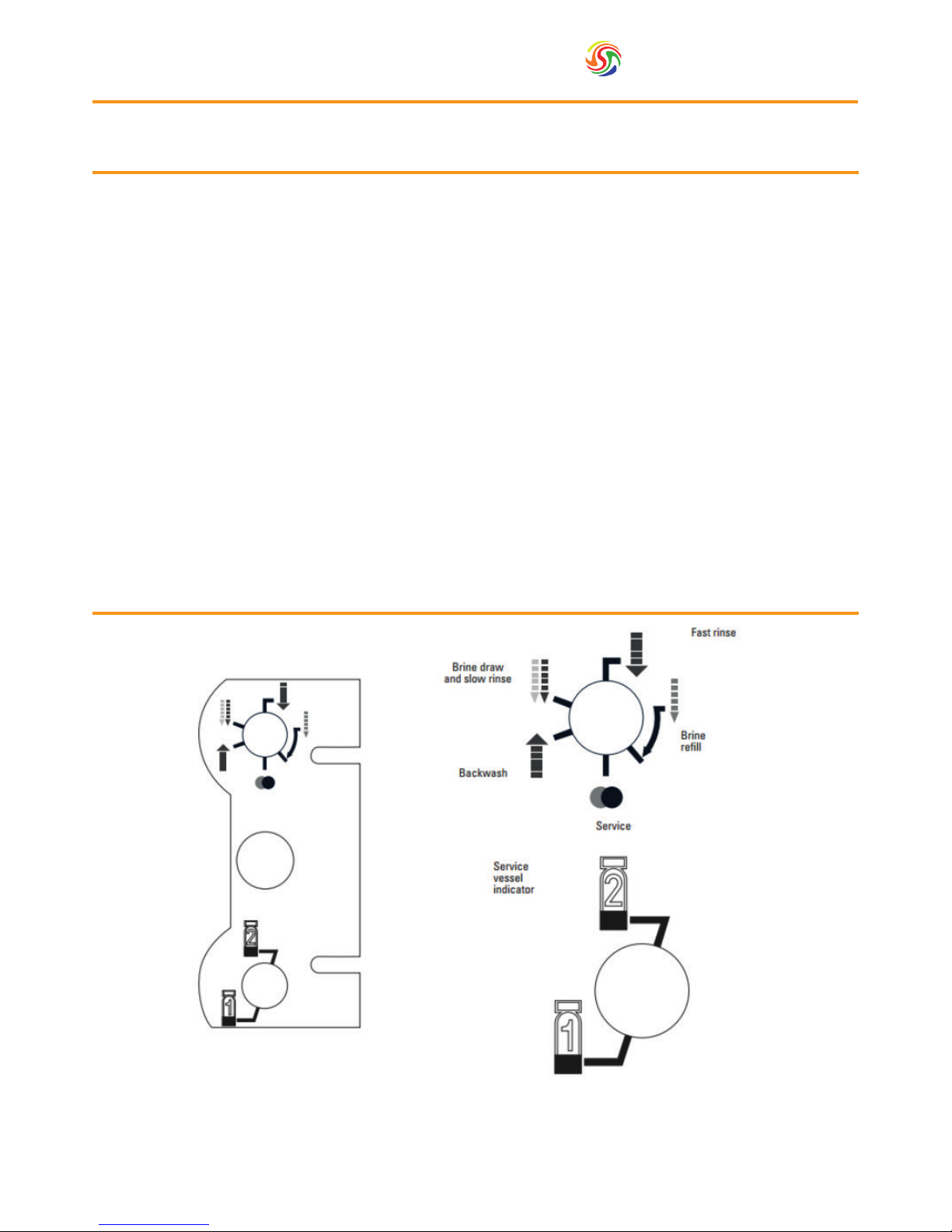
On the side of the motor there is a diagram which illustrates various information regarding the valve’s
regeneration cycle. The top arrow indicates the regeneration cycle. The bottom arrow indicates which tank is in
service. This information will have to be entered during the valve programming.
6.2. Valve’s Regeneration Cycle
Page 8

Spectrum
TM
8
6. Assembly & Start-Up
6.3. Start-Up
1. Fill the brine tank until the water reaches approximately half way up the tank.
2. Add salt until the tank in total is approximately ¾ full.
3. Switch on the electrical power .
N.B. If the valve has a bypass function, place the system in the bypass position.
4. Turn on the mains water supply.
5. Open a cold soft water tap nearby and allow to run until all foreign material has been removed from the system.
6. Once clean, close the soft water tap.
7. Move the bypass in service position and allow water to ow into the pressure vessels.
8. Open a cold soft water tap nearby and allow to run until the system has been purged of air.
9. Plug the valve into a power source. Once the valve has been connected to a power source, it may cycle on its
own in order to return to the service position.
10. Start regeneration by pressing the button on the controller and to bring the 2nd (slave) vessel into service.
Run through the cycle programmes in order to empty residual air in the rst vessel.
11. Repeat step 10 for the second vessel.
12. Once complete, press and allow the valve to go through a full cycle independently.
Page 9

9
Spectrum
TM
7. Programming &
Operation
In green are the options to select to ensure the proper operation of your system
In yellow are values to input based on your individual installation.
Abbreviation Parameter Option Abbreviation Options Functions
DF Display format
GAL Gallons
Ltr Litres
VT Valve type
dF1b Standard downow/Upow single backwash
dF2b Standard downow/Upow double backwash
Fltr Filter
Ufbd Upow brine rst
UFtr Upow lter
Othr Other
CT Control type
Fd Meter (ow) delayed
Fl Meter (ow) immediate
tc Time clock
dAY Day of week
NT Number of tanks
1 Single tank system
2 Two tank system
TS Tank in service
U1 Tank 1 in Service
U2 Tank 2 in Service
C Unit capacity Unit capacity (litres) for capacity, please view chart A
H Feedwater hardness Hardness of inlet water
RS Reserve selection
SF Percentage safety factor
rc Fixed reserve capacity
SF Safety factor Percentage of the system capacity to be used
RC Fixed reserve Fixed volume to be used as a reserve
DO Day override The systems day override setting
RT Regen time The time of day the system will regenerate
BW, BD, RR, BF
Regen cycle step
times
The time duration for each regeneration step.
Adjustable from OFF and 0-199 mins.
Note if “other” is chosen under “Valve Type” then R1,
R2, R3 etc will be displayed instead
D1, D2, D3, D4,
D5, D6 & D7
Day of week settings
Regeneration setting (ON or OFF) for each day of the
week on day-of-week systems
CD Current day The current day of the week
FM Flow meter type
t0.7 3/4” Turbine meter
P0.7 3/4” Paddle wheel meter
t1.0 1” Turbine meter
P1.0 1” Paddle wheel meter
t1.5 1.5” Turbine meter
P1.5 1.5” Paddle wheel meter
P2.0 2” Paddle wheel meter
GEN Generic or other meter
Page 10
Spectrum
TM
10
7. Programming &
Operation
7.1. Timer Operation
Features of the SXT:
• Power backup that continues to keep time and the passage of days for a minimum of 48 hours in the event of
power failure. During a power outage, the control goes into a power-saving mode. It does not monitor water
usage during a power failure, but it does store the volume remaining at the time of power failure.
• Settings for both valve (basic system) and control type (method used to trigger regeneration).
• Day-of-the-Week controls.
• While in service, the display alternates between time of day, volume remaining or days to regeneration, and tank
in service (twin tank systems only).
• The Flow Indicator ashes when outlet ow is detected.
• The Service Icon ashes if a regeneration cycle has been queued.
• Regeneration can be triggered immediately by pressing the Extra Cycle button for ve seconds.
• The Parameter Display shows the current Cycle Step (BW, BF, RR, etc) during regeneration, and the data display
counts down the time remaining for that cycle step. While the valve is transferring to a new cycle step, the
display will ash. The parameter display will identify the destination cycle step (BW, BF, RR, etc) and the data
display will read “----”. Once the valve reaches the cycle step, the display will stop ashing and the data display
will change to the time remaining. During regeneration, the user can force the control to advance to the next
cycle step immediately by pressing the extra cycle button.
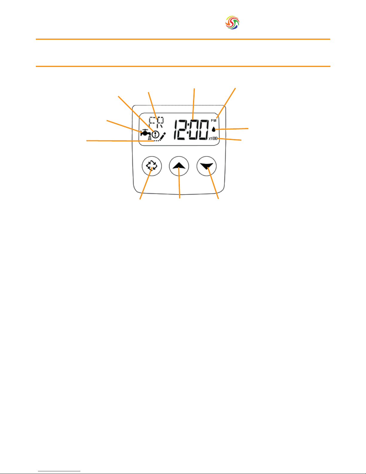
Parameter
Display
Data
Display
PM
Indicator
Flow Indicator
x1000 Indicator
Error/
Information
Icon
Service Icon
Programming
Icon
Extra Cycle
Button
Up
Button
Down
Button
Page 11

11
Spectrum
TM
8. Master Programming
Mode
When the Master Programming Mode is entered, all available option setting displays may be viewed and set as
needed. Depending on current option settings, some parameters cannot be viewed or set.
8.1. Setting the Time of Day
1. Press and hold either the ‘Up’ or ‘Down’ buttons until the programming icon replaces the service icon and the
parameter display reads ‘DO’.
2. Adjust the displayed time with the ‘Up’ and ‘Down’ buttons.
3. When the desired time is set, press the ‘Extra Cycle’ button to resume normal operation. The unit will also return
to normal operation after 5 seconds if no buttons are pressed.
8.2. Entering Master Programming Mode
Set the Time of Day display to 12:01 P.M. Press the ‘Extra Cycle’ button (to exit Setting Time of Day mode). Then
press and hold the ‘Up’ and ‘Down’ buttons together until the programming icon replaces the service icon and the
Display Format screen appears.
8.3. Exiting Master Programming Mode
Press the ‘Extra Cycle’ button to accept the displayed settings and cycle to the next parameter. Press the ‘Extra
Cycle’ button at the last parameter to save all settings and return to normal operation. The control will automatically
disregard any programming changes and return to normal operation if it is left in Master Programming mode for 5
minutes without any keypad input.
8.4. Resets
Soft Reset: Press and hold the ‘Extra Cycle’ and ‘Down’ buttons for 25 seconds while in normal Service mode. This
resets all parameters to the system default values, except the volume remaining in meter immediate or meter delayed systems and days since regeneration in the time clock system.
Master Reset: Hold the ‘Extra Cycle’ button while powering up the unit. This resets all of the parameters in the unit.
Check and verify the choices selected in Master Programming Mode.
Page 12

Spectrum
TM
12
Parameter Value Description Parameter Image
1. Display format DF Ltr
This is the rst screen that appears when
entering Master Programming Mode.
The Display Format setting speci es
the unit of measure that will be used for
volume and how the control will display
the Time of Day. This option setting is
identi ed by “DF” in the upper left hand
corner of the screen.
2. Valve type VT dF1b
Press the Extra Cycle button. Use
this display to set the Valve Type. The
Valve Type setting speci es the type
of cycle that the valve follows during
regeneration. Note that some valve
types require that the valve be built
with speci c subcomponents. Ensure
the valve is con gured properly before
changing the Valve Type setting. This
option setting is identi ed by “VT” in
the upper left hand corner of the screen.
3. Control type CT Fl
Press the Extra Cycle button. Use this
display to set the Control Type. This
speci es how the control determines when
to trigger regeneration. For details on how
the various options function, refer to the
“Timer Operation” section of this service
manual. This option setting is identi ed by
“CT” in the upper left hand corner of the
screen.
4. Number of tanks NT 2
Press the Extra Cycle button. Use this
display to set the Number of Tanks
in your system. This option setting is
identi ed by “NT” in the upper left
hand corner of the screen.
5. Tank in service TS U1
Press the Extra Cycle button. Use this
display to set whether tank one or tank
two is in service. This option setting is
identi ed by “TS” in the upper left hand
corner of the screen.
This parameter is only available if the
number of tanks has been set to 2.
There are two possible settings:
Look on the side label next to the
motor, the bottom arrow indicates
which tank is in service. If the arrow
indicates tank 1, then select U1. If the
arrow indicates tank 2 then choose U2–.
8. Master Programming
Mode
Page 13

13
Spectrum
TM
8. Master Programming
Mode
Parameter Value Description Parameter Image
6. Unit capacity C
Press the Extra Cycle button. Use this
display to set the Unit Capacity. This
setting speci es the treatment capacity
of the system media. Enter the capacity
of the media bed in grains of hardness
when con guring a softener system, and
in the desired volume capacity when
con guring a lter system. This option
setting is identi ed by “C” in the upper
left hand corner of the screen.
The Unit Capacity parameter is only
available if the control type has been set
to one of the metered options. Use the
Up and Down buttons to adjust the value
as needed. Input the value indicated in
the programming chart corresponding
to your model.
7. Feed water
hardness
H
Press the Extra Cycle button. Use this
display to set the Feed water Hardness.
Enter the feed water hardness in the
same unit chosen for determining the
capacity .volume for softener systems,
This option setting is identi ed by “H”
in the upper left hand corner of the
screen. Use the Up and Down buttons
to adjust the value as needed.
8. Reserve selection RS rc
Press the Extra Cycle button. Use this
display to set the Safety Factor. Use this
display to select the type of reserve to
be used in your system. This setting is
identi ed by “RS” in the upper left-hand
corner of the screen
9. Safety factor SF 0-50%
Press the Extra Cycle button. Use this
display to set the Safety Factor. This
setting speci es what percentage of
the system capacity will be held as a
reserve. Since this value is expressed
as a percentage, any change to the unit
capacity or feed water hardness that
changes the calculated system capacity
will result in a corresponding change to
the reserve volume. This option setting
is identi ed by “SF” in the upper left
hand corner of the screen. Use the Up
and Down buttons to adjust the value
from 0 to 50% as needed.
Page 14

Spectrum
TM
14
Parameter Value Description Parameter Image
10. Fixed reserve
capacity
RC
Press the Extra Cycle button. Use this
display to set the Reserve Capacity. This
setting speci es a xed volume that
will be held as a reserve. The reserve
capacity cannot be set to a value
greater than one-half of the calculated
system capacity. The reserve capacity is
a xed volume and does not change if
the unit capacity or feed water hardness
are changed. This option setting is
identi ed by “RC” in the upper left-
hand corner of the screen. Use the Up
and Down buttons to adjust the value as
needed.
11. Day override DO
This setting speci es the maximum
number of days between regeneration
cycles. The system will regenerate
regardless of usage if the days since
last regeneration cycle equal the
day override setting. Setting the day
override value to “OFF” disables this
function. This option setting is identi ed
by “DO” in the upper left hand corner
of the screen. Use the Up and Down
buttons to adjust the value as needed.
This parameter is dependant by your
individual needs.
12. Regeneration
time
RT
Press the Extra Cycle button. Use this
display to set the Regeneration Time.
This setting speci es the time of day the
control will initiate a manually queued,
or day override triggered regeneration.
This option setting is identi ed by “RT”
in the upper left hand corner of the
screen. Use the Up and Down buttons
to adjust the value as needed.
13. Regeneration
cycle step times
BD
BF
BW
RR
SV
0-199
Press the Extra Cycle button. Use this
display to set the Regeneration Cycle
Step Times. The different regeneration
cycles are listed in sequence based on
the valve type selected for the system,
and are identi ed by an abbreviation in
the upper left-hand corner of the screen.
The abbreviations used are listed below
although not necessarily in that order.
The values to input are dependent on
your own model and can be found in
the table in Section 11. Use the Up and
Down buttons to adjust the value as
needed. Press the Extra Cycle button to
accept the current setting and move to
the next parameter.
8. Master Programming
Mode
Page 15
15
Spectrum
TM
8. Master Programming
Mode
Parameter Value Description Parameter Image
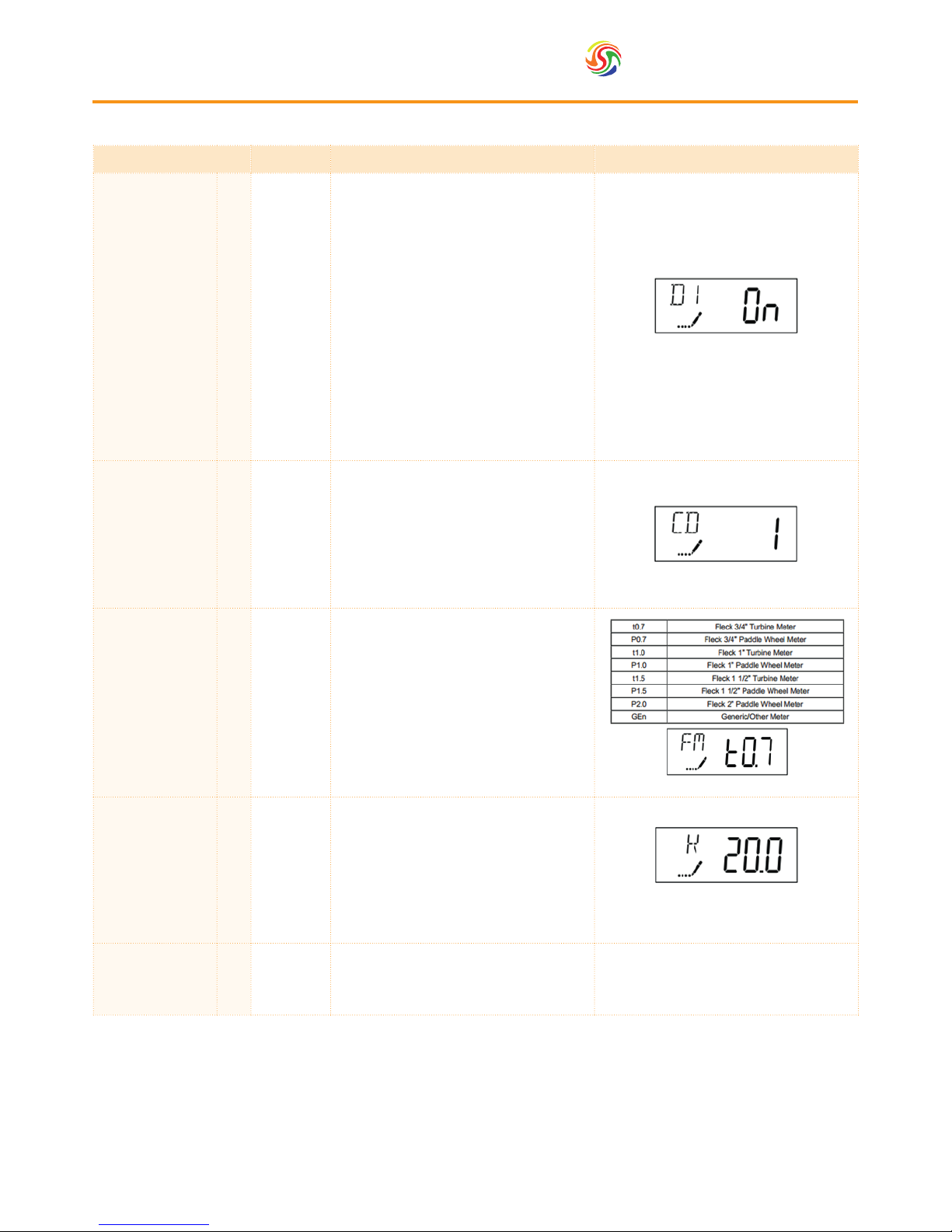
14. Day of week
D1
D2
D3
D4
D5
D6
D7
ON or OFF
Press the Extra Cycle button. Use this
display to set the regeneration schedule
for a system con gured as a Day of
Week control. The different days of the
week are identi ed as D1, D2, D3, D4,
D5, D6, and D7 in the upper left-hand
corner of the display. Set the value to
“ON” to schedule a regeneration or
“OFF” to skip regeneration for each
day. Use the Up and Down buttons to
adjust the setting as needed. Press the
Extra Cycle button to accept the setting
and move to the next day. Note that
the control requires at least one day to
be set to “ON.” If all 7 days are set to
“OFF”, the unit will return to Day One
until one or more days are set to “ON.”
15. Current day CD 1-7
Press the Extra Cycle button. Use this
display to set the current day on systems
that have been con gured as Day of
Week controls. This setting is identi ed
by “CD” in the upper left-hand corner
of the screen. Use the Up and Down
buttons to select from Day 1 through
Day 7.
16. Flow meter type FM
Press the Extra Cycle button. Use this
display to set the type of ow meter
connected to the control. This option
setting is identi ed by “FM” in the
upper left-hand corner of the screen.
Use the Up and Down buttons to select
one of the 7 available settings.
The values to input are dependent on
your own model and can be found in the
table in Section 11.
17. Meter pulse
setting
K
Press the Extra Cycle button. Use this
display to specify the meter pulse
setting for a non-standard ow meter.
This option setting is identi ed by “K”
in the upper left-hand corner of the
screen. Use the Up and Down buttons
to enter the meter constant in pulses
per unit volume.
18. End of master
programming
mode
Press the Extra Cycle button to save all
settings and exit Master Programming
Mode.
Page 16

Spectrum
TM
16
9. User Programming Mode
Abbreviation Parameter Description
DO Day override The time’s day override setting
RT Regeneration time
The time of day that the system will regenerate
(meter delayed timeclock, and day-of-week systems)
H Feed water hardness
The hardness of the inlet water - used to calculate system capacity for
metered systems
RC or SF Reserve capacity The xed reserve capacity
CD Current day The current day of week
N.B. Press the Up and Down buttons for ve seconds while in service, and the time of day is NOT set to 12:01 PM.
9.1. Timer Operation
Parameter Description Parameter Image
1. Day override DO
Use this display to adjust the Day Override.
This option setting is identi ed by “DO” in
the upper left hand corner of the screen.
2. Regeneration time RT
Press the Extra Cycle button. Use this display
to adjust the Regeneration Time. This option
setting is identi ed by “RT” in the upper left
hand corner of the screen.
3. Feed water hardness H
Press the Extra Cycle button. Use this display
to adjust the Feed Water Hardness. This
option setting is identi ed by “H” in the
upper left hand corner of the screen.
4. Reserve capacity RC
Press the Extra Cycle button. Use this display
to adjust the Fixed Reserve Capacity. This
option setting is identi ed by “RC” or “SF”
in the upper left-hand Corner of the screen.
Page 17

17
Spectrum
TM
10. Diagnostic Programming
Mode
Abbreviation Parameter Description
FR Flow rate Displays the current outlet ow rate
PF Peak ow rate Displays the highest ow rate measured since the last regeneration
HR Hours in service Displays the total hours that the unit has been in service
VU Volume used Displays the total volume of water treated by the unit
RC Reserve capacity
Displays the system’s reserve capacity calculated from the system capacity, feed
water hardness, and safety factor
SV Software version Displays the software version installed on the controller
N.B. Some items may not be shown depending on timer con guration. The timer will exit Diagnostic Mode after 60
seconds if no buttons are pressed. Press the Extra Cycle button to exit Diagnostic Mode at any time.
Press the Up and Extra Cycle buttons for ve seconds while in service.
10.1. Diagnostic Programming Mode Steps
Parameter Description Parameter Image
1. Flow rate FR
Use this display to view the current Flow Rate.
This option setting is identi ed by “FR” in
the upper left hand corner of the screen. It is
expressed in m3/hr.
2. Peak ow rate PF
Press the Up button. Use this display to view
the Peak Flow Rate since the last regeneration
cycle. This option setting is identi ed by “PF”
in the upper left hand corner of the screen. Its
expressed in m3/hr.
3. Hours in service HR
Press the Up button. Use this display to
view the Hours in Service since the last
regeneration cycle. This option setting is
identi ed by “HR” in the upper left hand
corner of the screen.
4. Volume used VU
Press the Up button. Use this display to view
the Volume Used since the last regeneration
cycle. This option setting is identi ed by “VU”
in the upper left hand corner of the screen.
5. Reserve capacity RC
Press the Up button. Use this display to view
the Reserve Capacity. This option setting is
identi ed by “RC” in the upper left hand
corner of the screen.
6. Software version SV
Press the Up button. Use this display to view
the Software Version. This option setting
is identi ed by “SV” in the upper left hand
corner of the screen.
7. End diagnostic
programming mode
Press the Extra Cycle button to end Diagnostic
Programming mode.
Page 18

Spectrum
TM
18
11. Programming Charts
The chart below can be used to help programme steps 13 and 16 in the Master Programming Mode.
SoftH20-DUO Programming Chart
Parameter
Softener
CapacityCBackwashBWBrine drawBDRapid rinseRRBrine rell
BR
Total
Flow meter
FM
WTP-SOFT30D 150 6 60 4 12 82 0.75
WTP-SOFT50D 250 6 70 4 10 90 0.75
WTP-SOFT75D 375 6 70 4 13 93 0.75
WTP-SOFT100D 500 6 70 6 10 92 0.75
WTP-SOFT150D 750 8 80 8 16 112 1.5
WTP-SOFT250D 1250 10 90 10 14 124 1.5
WTP-SOFT350D 1750 10 90 10 18 128 1.5
Page 19

19
Spectrum
TM
Problem Possible Cause Possible Solution
A. Controller does not work
1. Power off
2. Transformer is not plugged in
3. Defective power cord
4. Defective transformer
1. Switch on power
2. Connect to constant power source
3. Replace cord
4. Replace the transformer
B. Incorrect time of regeneration 1. Power outage causes inaccurate timing 1. Reset the timer
C. Leaking 1. Loose connections 1. Tighten joints
D. Noisy 1. Air pressure in the system 1. Re-backwash the system to vent air
E. Milk-white water 1. Air exists in the system 1. Turn on the tap to vent air
F. Unsatised water hardness
1. Poor raw water quality
2. Time of regeneration is too long
3. Resin disabled
1. Contact your supplier for assistance
2. Reset time of regeneration
3. Re-regeneration or use new resin
G. Softener fails to use salt
1. Water pressure is too low
2. Brine line blocked
3. Injector is blocked
4. Internal control leak
1. Line pressure must be at least 20 psi
2. Clean brine line
3. Clean or replace injector & screen
4. Check piston, seals and spacers
H. Brine container overow 1. Rell time too long 1. Contact your supplier for assistance
I. Water hardness remains
1. Fail to regenerate automatically
2. Brine concentration is poor
3. Injector is plugged
1. Check power of controller
2. Keep brine tank full of salt
3. Disassemble the injector and clear it
by washing with water
K. Untreated water leakage
during service
1. Improper regeneration
2. Leaking of bypass valve
3. O-ring around riser tube damaged
4. Incorrect regeneration cycle setting
1. Repeat regeneration making certain
that the correct salt dosage is set
2. & 3. Replace O-ring
4. Reset regeneration cycle
12. Troubleshooting
Important Notice
The controlling components are driven by an electric circuit. Some programmed parameters will be lost if a
power outage lasts over 8 hours and the water softener will carry out the regeneration process at the incorrect
time. We strongly recommend that after a power outage, users should check the time and adjust accordingly.
12.1. DUO System
Page 20

Spectrum
TM
20
12. Troubleshooting
12.2. DUO Valve
Problem Possible Cause Possible Solution
A. Unit fails to initiate a
regeneration cycle
1. No power supply Check electrical service, fuse, etc
2. Power Failure Reset time of day
B. Water is hard
1. By-pass valve open Close by-pass valve
2. Out of salt Add salt to tank
3. Plugged injector / screen Clean parts
4. Flow of water blocked to brine tank Check brine tank rell rate
5. Leak between valve and central tube
Check if riser tube is cracked or o-ring is damaged.
Replace faulty parts
6. Internal valve leak Replace valve seals, spacer and piston assembly
C. Salt use is high 1. Rell time is too long Check rell time setting
D. Low water pressure
1. Iron or scale builds up in line feeding unit Clean pipes
2. Iron build up inside valve or tank
Clean control and add resin cleaner to clean the
bed. Increase regeneration frequency
3. Inlet of control blocked due to foreign matter Remove piston and clean control valve
F. Too much water in
brine tank
1. Blocked injector or screen Clean parts
2. Foreign material in brine tank Clean parts
G. Unit fails to draw
brine
1. Drain line ow control is blocked Clean parts
2. Injector or screen is blocked Clean parts
3. Inlet pressure too low Increase pressure to 25 PSI
4. Internal valve leak Replace seals, spacers and piston assembly
H. Valve continuously
cycles
1. Broken Gear Replace faulty parts
I. Flows to drain
continuously
1. Valve settings incorrect Check valve settings
2. Foreign material in control valve Clean control
3. Internal leak Replace seals, spacers and piston assembly
Page 21

21
Spectrum
TM
13. Cautions
1. Without reading and understanding the contents of this user manual, DO NOT perform any operations on the
control valve.
2. Strictly prohibit a leaning position when shipping, installing and using this product as this could cause damage.
3. During the regeneration, water from the tap will NOT be softened. It is NOT recommended to use water during
regeneration; otherwise a negative effect on the regeneration result will occur.
4. Initiate a regeneration cycle when the softener has been inactive for a long period of time and then turn on the
tap for several minutes before resuming normal use.
5. Do not disconnect power during service to prevent timer distribution.
6. If water usage or hardness of raw water dramatically increases (compared to the normal usage), then the frequency
of regeneration should increase.
7. Hot water could cause severe damage to the softener system, for water boiler and water heaters users, ensure the
total-run of the piping between the softener and the boiler is not less than 3 meters. It is recommended to install
a check valve between the lter and the boiler if unable to meet the required piping length.
8. The input water pressure must be between 2 - 8 bar.
9. No chemicals should be present at the inlet and outlet connecting sectors.
10. Besides the system, spare part connection materials are not included in the scope of the manufacturer’s warranty.
11. The required environmental temperature for a softener is 1 - 42°C. Below this will cause the softener to malfunction.
12. Do not apply pressure to the softener.
13. Indoor installation is preferred. Avoid exposure to direct sunlight, radiation from other heating sources and avoid
extreme weather conditions including rain and snow.
14. Use salt granules or tablets designed for softeners.
15. No tools should be used for connecting the plastic parts as over tightening or excessive force could result in
damage.
16. If necessary use food grade silica sealant for lubricating rubber O-rings.
17. Only qualied personnel should adjust or remove the adaptor locking clips on the reverse of the valve, as this can
tamper with the valve settings. Should this be required pressure must rstly be discharged from inside the water
softener.
Page 22

Spectrum
TM
22
14. Technical Information
Model (litres of resin)
30 50 75 100 150 250 350
Maximum Operating Temperature (ºC)
42
Minimum Operating Temperature (ºC)
2
Maximum Operating Pressure (bar)
8
Minimum Operating Pressure (bar)
2
Optimal Flow Rate (m3/hr)
1 2 3 3 6 8.4 8.4
Max Flow Rate (m3/hr)
4.5 4.5 4.5 4.5 8.6 8.6 8.6
Inlet / Outlet (")
¾ ¾ ¾ ¾ 1½ 1½ 1½
Valve
FLECK
9000/9100
FLECK
9000/9100
FLECK
9000/9100
FLECK
9000/9100
FLECK
9500
FLECK
9500
FLECK
9500
Drain (")
1 1 1 1 1 1 1
Brine Line (")
⅜ ⅜ ⅜ ⅜
½ ½ ½
Power Requirements (V)
240V
50Hz
240V
50Hz
240V
50Hz
240V
50Hz
240V
50Hz
240V
50Hz
240V
50Hz
Resin Volume (l)
30 50 75 100 150 250 350
Salt Consumption Per Regeneration (kg)
4.5 7 11 14 21 35 50
Pressure Tank Thread (")
2½ 2½ 2½ 4 4
Vessel Size
09x35 10x54 13x54 14x65 16x65 21x62 24x72
Brine Tank Volume (l)
140 140 140 350 350 350 500
Brine Tank Dimensions (mm)
582x362
x904
582x362
x904
582x362
x904
ø 740 x
1275
ø 740 x
1275
ø 740 x
1275
ø 840 x
1335
Total Height (mm)
1100 1600 1600 1860 1960 1960 1960
Total Weight (kg)
70 100 180 250 350 580 750
 Loading...