

Page 1

1
Page 2

CAUTION!
• Never install telephone wiring during a lightning storm.
• Never install telephone jacks in we t locations unless the jack is
specifically designed for wet locations.
• Never touch uninstalled telephone wires or terminals unless the
telephone line has been disconnected at the network interface.
• Use ca ution wh en installing or modifying t eleph one lines.
2
Page 3

Congratulations on the purchase of your TeleMatrix Spectrum
TM
PLUS
includes advanced features that are suitabl e in today’s business
environment. TeleMatrix designed the Spectrum PLUS
model SP400 telephone. The Spectrum PLUSTM SP400
TM
SP400 to
be simple to install and easy to use.
Your Spectrum PLUS
TM
SP400 telephone is a precision electronic
device that requires minimum maintenance. Please be sure to
read this user’s guide to become familiar with the wiring and
functionality of this product.
As specified by FCC regulation, we are required to inform you of specific
governmental and compliance regulatory requirements, safety notices,
safety instructions and other informative information. TeleMatrix, Inc.
provides this information in a separate manual. We pack the separate
Compliance and Safety Manual within each outer box or product box when
shipped.
Prior to reading this operation manual and prior to setting up your
telephone, please refer to the Compliance and Safety Manual.
3
Page 4

Features ......................................................................... 5
Controls ……..................................................................... 6
Part List …………………………………………………………………………………... 10
Installation ..................................................................... 11
Wall Mounting ............................……................................ 14
Switch Settings ..................….…....................................... 16
Programming ..…....................…....................................... 17
Headset Installation and Operation………............................... 22
Operation ………………………………………………………………………………... 24
Care and Maintenance ……………………………………………………..……. 32
Service ……………………………………………………………………………………. 33
Warranty .……………………………………………………………………………….. 34
4
Page 5

• One Line Operation
• SteelTrap
• FreeSpeech
Speakerphone
TM
Memory Technology (No Batteries Required)
TM
Talk Feature: Allows Free Toggle between Handset, Headset and
• Visual Message Waiting Indication* – Auto Detection for SDT, FSK or NEON;
LED uses switch
• TouchLite
TM
One Touch Message Retrieval Key
• 2-Way Speakerphone (Half Duplex)
• Headset Port with ON/OFF Switch (built-in Amplifier)
• Microphone Mute with LED Indicator
• Eleven (11) Speed Dial Locations
• Electronic Hold with LED Indicator (with Line Hold or System Hold Switch)
• Audible Ring Tone Selection (4 options)
• Speaker, Headset, and Ringer Volume Control (8 selections)
• Convenient Data Port
• ADA Compliant Handset with 8-step Volume Control
• Disconnect Key to Activate New Call
• Last Number Redial
• Programmable Flash Key
• Programmable Pause Key
• Desk or Wall Mountable
• Fully Modular, Easy To Install
Class Visual Message Waiting are features that require subscription to your local telephone company
provided service. This telephone featur es will no t wo rk unless you are a subscriber.
5
Page 6
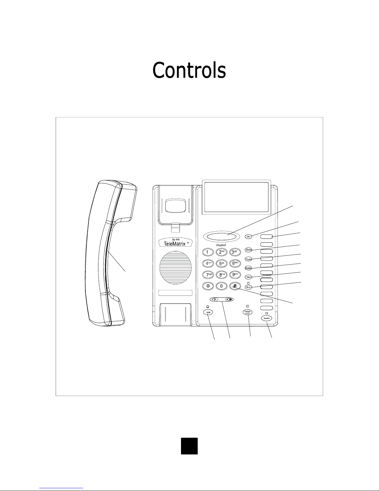
TOP PANEL
(13)
(14)
(2)
(1)
(3)
(4)
(5)
(6)
(7)
(8)
6
(9)
(12)
(11)
(10)
Page 7

1. Speed Dial Feature Keys……………..… Eleven (11) one-touch keys used for speed dialing.
2. Disconnect Key ……………………...…….. Used to disconnect the line or place a new call.
3. Store Key……………………………….….….. Used to program user features.
4. Pause Key ...............................… Used to place a timing delay when dialing.
5. Redial Key ......................…………… Redials the last number dialed.
6. Flash Key ..................……………..…. Provides a timed line break.
7. Mute Key …………………………….………... Disables the handset and speaker phone microphones.
8. Numeric Dial Pad ………………...………. Used for dialing.
9. Hold Key ………………………………..…….. Lighted key used for placing callers on hold.
10. Speaker Key .………………................ Used to turn the speakerphone ON or OFF.
11. Headset ON/OFF Key ……………………. Lighted key used to turn the headset ON or OFF.
12. Volume Bar …………………..………………. Adjusts the loudness of the handset receiver, the head
set, and/or the speaker.
13. Handset ……………………………….……... Hearing-aid compatible handset.
TM
14. TouchLite
Key...……………………...... Message Waiting Lamp (LED indicator) that blinks
to indicate a new message in the user’s voice mail
box (user must be subscribed to a messaging system).
7
Page 8
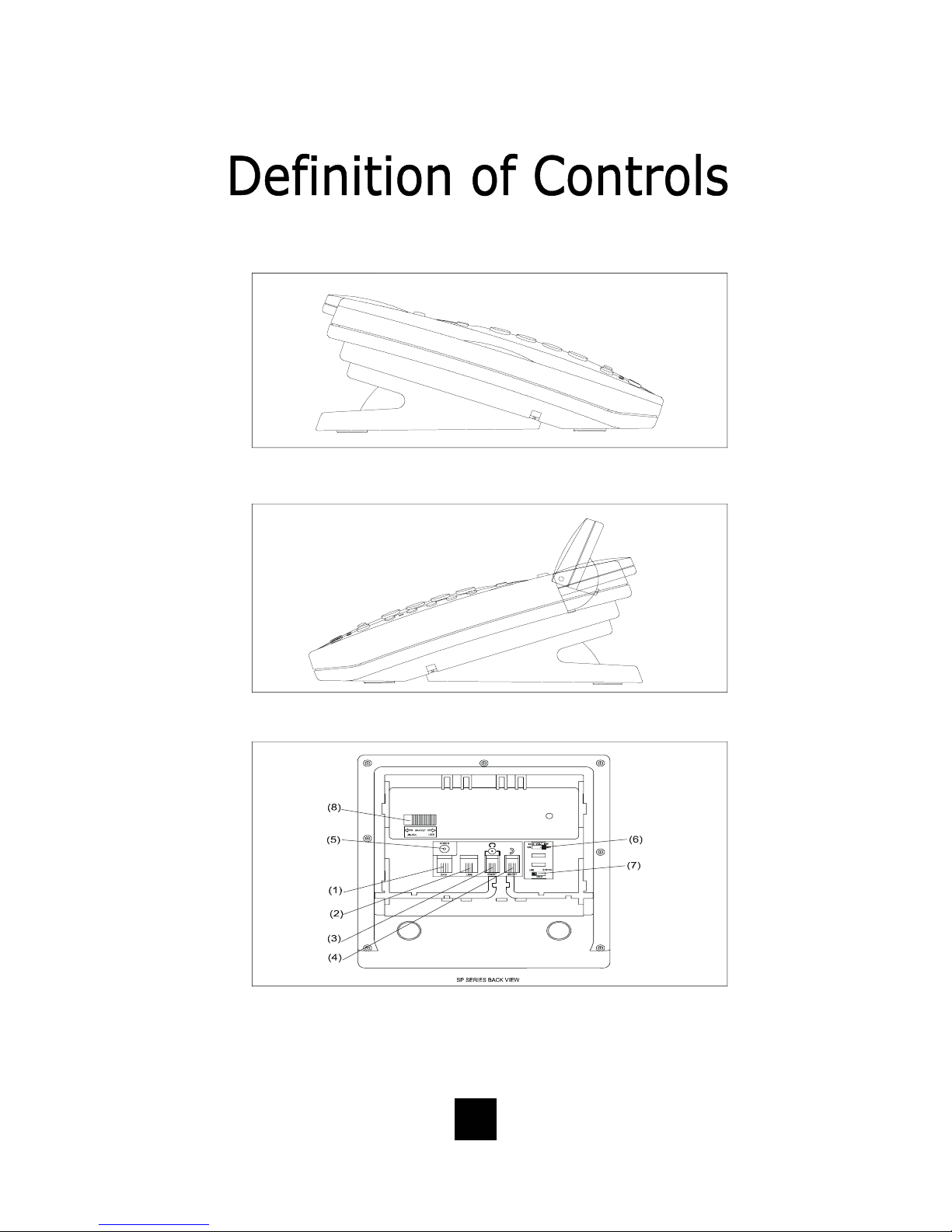
LEFT SIDE
RIGHT SIDE
REAR
8
Page 9

1 Data Port .................................... Convenient port to connect a computer,
modem, fax or answering device.
2 Line Jack ………………………………………... Modular receptacle for connecting the
line cord.
3 Headset Jack .............................. Convenient RJ port or 2.5mm coaxial port
used to connect an optional headset.
4 Handset Jack .............................. Connection for handset coil cord.
5 Power Adapter Receptacle ……..……. For optional coaxial power adapter.
6 Low Voltage MW Switch ………………… Selects low voltage message waiting.
7 Hold Key Switch ……………...……………. Used to select line hold or system hold.
8 Elevation Stand Lock ……………………. Used to “lock” the elevation stand.
9
Page 10
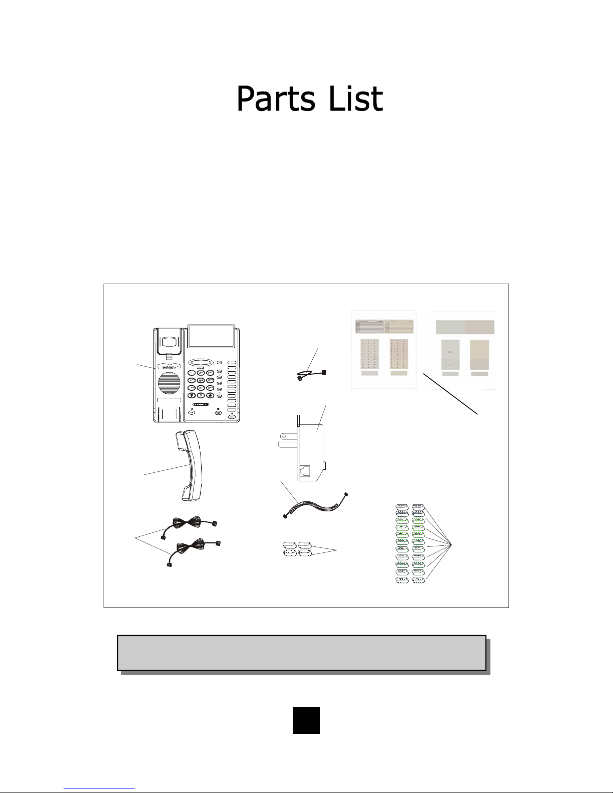
Parts Check List
The following parts are included with the Spectrum PLUS
1. Base Unit
2. Handset
3. Two (2) 15 -foot Modular telephone line cords
4. 10-foot Modular coiled handset cord
5. 6-inc h Modular wall mount line cord
6. Power Adapter
7. Twenty-two (22) Speed Dial Preprinted Keycaps
8. Fo ur (4 ) Additio nal C le ar Keycaps
9. Two (2) Index Sheets
(5)
(1)
(6)
P
H
O
N
E
TM
SP400:
For models SP-100 an d S P -2 0 0
11
22
33
For models with memory: SP- 30 0,S P- 400, SP - 550, SP- 750, SP -83 12
44
55
66
77
88
99
10 10
11 11
Use this pe rf ora ted sheet to custom ize yo u r telephone
1
For models SP-100 and SP-200
2
11
22
33
44
55
66
77
88
99
10 10
11 11
2 3
31
(9)
(3)
(2)
OUT
(4)
(8)
11
22
33
For mo de ls with me mo ry: S P-300,SP-400,SP-550 ,SP-750,SP-8312
44
55
66
77
88
99
10 10
11 11
11
22
33
44
55
66
77
88
99
10 10
11 11
(7)
NOTE: Spectrum PLUSTM Line Cords are 6-Pin 6-Conduc tor Line cords
(6P6C line cord). Replacement Line Cords must be same.
10
Page 11

120V AC Outlet Recovery Power Adapter (provided)
The 120 VOLT AC OUTLET RECOVERY POWER ADAPTER i s an featu red TeleMatrix
product. It provides both the telephone lines and the power source in one cable
(6P6C line cord) and is designed to recover the use of the power outlet.
Connector Configuration
The 120 Volt Outlet Recovery Power Adapter has two (2) modular jacks. One
jack is labeled “LINE” and the other jack is labeled “PHONE”. These jacks allow
for a fully modular installation.
Power Adapter “LINE” Connection
The power adapter “LINE” connection is
used to connect the telephone line from
the wall jack to the power adapter.
Using one of the 15-foot modular
telephone li ne cords, connect one end of
IN
L2L1+L2
NEL
_
the cord to the RJ14 telephone jack on
the wall or base board. The remaining
end of the cord plugs into the “IN” side
of the power adapter.
Power Adapter “PHONE” Connection
The power adapter “PHONE” connection
is used to provide both the telephone
lines and the power source to the
telephone. Using one of the 15-foot
modular telephone line cords, plug one
end of the line cord into the back of the
telephone. Plug the remaining end to
the power adapter jack labeled “OUT”.
Troubleshooting Note: If there is no power to the telephone
after connecting the line cords, c heck to see if the line cords
are inserted on the opposite sides of the adapter.
11
OUT
EHNOP
Page 12

Installing The Wall Power Adapter
(Optional Component)
This componen t i s b est u sed wh en wall
mounting the telephone. To install,
simply plug the power adapter into a
standard 120V AC power outlet. A
mounting hole is provided to secure
the power pack to the AC wall outlet.
Plug the AC power pack directly into
the wall outlet and then plug the coaxial connector into the receptacle
marked “POWER” located on the back
of the telephone.
POWER
120V AC POWER
ORDER SEPERATELY
Power Outlet Configuration
The Spectrum PLUS
TM
telephone requires
external power from a standard 120V
outlet (60Hz). It is rated 9VAC, 300mA.
IMPORTANT!
The telephone will not functio n if the line cord connections are not co rrect. Be sure that
the telephone line cord connections are not reversed (“LINE”/”PHONE”). Attach the line
!
cords to the power adapter and the wall befo re connecting to the telephone. Spectrum
TM
PLUS
Cords must be same.
Line Cords are 6-Pin 6-Conductor Line cords (6P6C line cord) . Replacement Line
12
Page 13

Connecting the Handset Cord
A 10-foot modular coil handset cord is
provided. (Be sure that the wall/desk
elevation stand has not been attached).
To install the cord, simply plug the
short end of the handset cord into the
modular jack on the handset. The long
end of the handset cord plugs into the
jack labeled “Handset” located on the
bottom of the Spectrum PLUS
TM
base
unit. Place th e line cord into the ha ndset coil cord channel located directly
below the jack.
Installing the Keycaps
Twenty-two (22) preprinted named
feature keycaps are provided to identify
the speed dial key.
There are eleven (11) clear keycaps
already installed. To install preprinted
keys, remove the clear keycap by
simply pulling up. Replace with the
preprinted keycaps or place hand
written paper index sheets under a
clear keycap. P rogram each speed dial
key for the specific function of the key.
CLEAR "SNAP-ON" KEY CAP
OR SILK SCREEN KEY CAP
PLASTIC TOP CAB I NET
Handset Cord
PLASTIC TOP CABINET
PLASTIC KEYTOP
NOTE: For speed dial programming instructions,
see the sect ion on “Pro grammin g Proc edure For
Spectrum PLUS
manual.
TM
Speed Dial Features” in this
There are four (4) additional clear keycaps and two (2) index sheets provided as
spares. Use t hese for y our own pe rsonal speed d ial iden tities. Write th e speed di al
name on the blank speed dial index cards and insert into the blank keycaps. Place
the keycap on the correct memory speed dial location. (see index sheets provided
in box).
The twenty-two preprinted keycap names are below:
Call Fwd On Call Back Paging Skip Msg Information
Call Fwd Off Cancel Call Back Ring Again FF Msg 911
Transfer Call Park Save Msg Rew Msg
Conf Call Pick-up Del Msg Em e rgency
DND Group Call Pick-up Rpt Msg Help Desk
13
Page 14

Wall Mounting the Spectrum PLUSTM Telephone
The Spectrum PLUSTM was designed to be
conveniently wall mounted without requiring
additional hardware.
Follow these easy steps:
1.The handset retaining clip must be in the correct
position to secure the handset into the handset
cradle. Engage the clip with your fingers and pull
the clip forward (towards you), rotate the clip 180º
and snap the clip back into place (figure 1). The
retaining clip cannot be removed.
1. UNSNAP
2. ROTATE 18 0 .
3. SN AP INTO PLACE.
1.LIFT CLIP OUT WITH
FINGERS. IT CANNOT BE
REMOVED BECAUSE IT
IS SPRING LOADED.
2. ROTATE THE
CLIP 1800 AND
IT WILL SMAP
BACK INTO THE OPPOSITE POSITION. AN
RETAINER CLIP
NOTE: CLIP IS
figure 1
2. The Spectrum PLUSTM has provisions for a
mounting wedge that must be correctly positioned.
This wedge allows the telephone to be viewed at a
correct angle when the phone is wall mounted.
Remove the wedge from the phone base (figure 2).
3. Secure the line cord, coil cord and any wiring i n
place prior to installing the wall mount wedge. The
wall mount base has extra large wiring channels
and strain relief poles for containing the wires in a
neat and orderly way. Wrap the wires around the
strain relief poles and then secure the wires
through the channel.
4. To wall mount, place the narrow edge at the top
edge of the phone base and slide the wedge upward into place (figure 3).
5. Lock the wall mount into position by sliding the
locking button to the r ight (figure 4).
Note: A 6-inch line cord is provided for when
the telephone is to be wall mounted. Connect
one end of the line cord to the phone jack and
the other end to the wall jack. Be sure to connect the power cord and line cords before plac-
ing mounting wedge on the bottom base. An
!
optional coaxial power supply can be used in
place of the supplied power supply. See your
local distributor for information.
Replace Mounting Wedge
figure 2
Replace Mounting Wedge
figure3
Lock Mounting Wedge
Desk Mounting
To install the wedge for desk mounting, be sure the lock mechanism is positioned to the left
clear of the locking arm. Place the wedge in the slots, wide end toward top of phone base
unit, and slide the wedge upw a rd into position. Lock the wedge into place.
figure 4
14
Page 15

Message Waiting Light Indicator
The Spectrum PLUS
TM
telephone has a
Message Waiting Light Indicator
Message Waiting (MW) Light Indicator (figure
1). The indicator will blink to indicate that a
new message is in the user’s voice mailbox.
The Spectrum PLUS
TM
supports the following
telephone or PBX supplied message waiting
signals:
1. Telephone Company VMWI Service* (FSK
signal compatible, subscription to local
telephone company is required).
2. Or, Audible Stutter Dial Tone (SDT) signals
provided by local telephone compan y.
3. Or, 90-Volt NEON message waiting light
indicator signal provided by a PBX.
4. Low Voltage LED message waiting light in-
dicator light signal is provided by a PBX.
The PBX system or telephone servi ce provider
has to activate the voice mail feature for the
!
light to illuminate and work properly. Be sure
that your telephone service provider or PBX
system has the compatible messaging service
available in your area or facility.
figure 1
NOTE: The Spectrum PLUS
telephone automatically reads the
Message Waiting (MW) signals
supplied by your service provider.
The LED signal supplied by a PBX
must have the LED Voltage switch
which is located on the bac k of the
telephone in the correct
position to operate the LED. See
the next page for instructions.
TM
Use this feature when alerting another that a saved message is in voice mail for that person or
use this feature when you simply want to turn the light off.
Be Aware: If there is a new incoming message and the telephone company continues to send
f
a new signal this light will re-activate. This will occur only when there is a new voice mail that
has not been heard.
How To Use: When on-hook, Press the “*” key for 3 to 5 seconds and the Message LED will
automatically turn on. At any time press “*” key for 3 to 5 seconds ,Message LED will turn off.
*Definition: VMWI is Visual Message Waiting Indic ation. This optio n requires a
d
subscription to your loc al telephone service provider for TouchLite
Feature Note: Message ON/OFF Notification.
15
TM
to activate.
Page 16

Low Voltage LED Switch
A low voltage LED switch is located on
the bottom of the phone. The switch
options are ON or OFF. The factory
default is OFF.
System Hold Feature Option Switch
A feature switch for different hold
functions is located on the bottom of
the phone. The switch options are
standard “LINE Hold” or programmable
“System Hold”*.
The standard “Line Hold” allows for
normal hold function operation. The
programmable “System Hold”* feature
is used for optional PBX system
operations.
The switch default is set at the factory
as standard “LINE Hold”.
* To program System Hold, follow the speed dial
instructions in this manual. To store the dialing pattern, press the HOLD key instead of the speed dial
memory key.
LOW VOLT MW
ON OFF
LOW VOLT MW
ON OFF
16
Page 17

Programming Flash Timing into Memory
Flash Timing can be programmed into the Spectrum PLUS
This function allows for a timed line break in the sequence of the dialing patterns
when using the speed dial keys. This function may be required for accessing line
features provided by your telephone system or local telephone company. The
flash timing options are 100 through 1000 milliseconds, programmable in 100mS
increments.
To Find the Correct Flash Timing
The factory default Flash Timing is programmed at 600mS and is the most commonly used timing option. However, the
timing can be reprogrammed between
100mS to 1000mS, when needed.
1. Check with your local service provider
or PBX provider to select the appropriate timing.
2. If different timing is required, follow
the Flash Time Programming instructions on the next page.
TM
speed dial memory.
Using A Flash When Dialing
To use a Flash when dialing, simply press the “FLASH” key at the appropriate point in
the number sequence being dialed from the key pad.
!
NOTE: Each “Flash” counts as 1-digit when stored into a speed dial memory location.
17
Page 18

Programming Flash Timing
Flash timing can be programmed for different timing options listed below.
1. Position the handset in the Off-Hook position (lift the handset).
2. Press the “STORE” key once.
3. Press “*” key for 3-seconds until an alert sound is heard.
4. Press the following keys on the keypad in the order shown:
For 100mS press "1", then “#”.
For 200mS press "2", then “#”.
For 300mS press "3", then “#”.
For 400mS press "4", then “#”.
For 500mS press "5", then “#”.
For 600mS press "6", then “#”.
For 700mS press "7", then “#”.
For 800mS press "8", then “#”.
For 900mS press "9", then “#”.
For 1000mS press "0", then “#”.
5. Place the handset cradle to the On-Hook position.
Go Off hook with handset, press “store” once, then “*” for
3-seconds to enter se t up mode, then “1”, then “#”. Place
the handset into cr a d le to the on-hook Pos ition.
!
Programming Example for 100mS
NOTE: The Flash Timing factory default is 600mS
18
Page 19

Programming Pause Timing
A Pause time between 1.0-seconds to 5.0-seconds can be programmed into memory.
This function allows for a delayed timing for those systems requiring a different time
delay and allows the user to delay the dialing pattern of a number. This function may
be required for accessing line features provided by telephone provider or local
telephone company. A speed dial number may need to pause during its dialing
sequence to ensure proper connections.
PROGRAMMING THE PAUSE TIME OPTION
Pause timing can be programmed for different timing options listed below.
1. Lift the Handset from it’s cradle so it is in a off-hook position.
2. Press the “STORE” key once.
3. Press the “#” key for 3-seconds until an alert sound is heard.
4. Program the pause time into memory by using the keypad. Press the following
keys on the keypad in the order shown for the desired pause time.
For 1.0-second press "1" "0" then “#”.
For 2.0-seconds press "2" "0" then “#”.
For 3.6-seconds press "3" "6" then “#”.
For 4.0-seconds press "4" "0" then “#”.
For 5.0-seconds press "5" "0" then “#”.
4. To exit the program mode, place the handset back in the cradle in an on-hook
position.
!
NOTE: If you require a pause time delay longer than the maximum setting of 5.0S,
!
stack the pauses within the dialing pattern to achieve the long e r timing .
NOTE: The default Pause time is 3.6-seconds.
19
Page 20

Programming a Pause into Speed Dial Memory
Pause time can be programmed into the speed dial memory. This function will delay the
dialing pattern of a number when stored in the phones speed dial memory. Multiple pauses
can be programmed into the dialing pattern for added delay time. To store a Pause into
Speed Dial memory, simply press the Pause key in the numbering sequence when programming Speed Dialing Keys. See programming Speed Dial Memory on the next page.
Programming Pause into Voice Mail
To store a Pause time into Voice Mail memory, simply press the Pause key in the numbering sequenc e when programmi ng the Voice Mail Speed Dial Key. See p rogramming Voi ce
Mail on the next page.
Note: Programming can
only be performed when
!
the phone is off-hook
NOTE: The default Pause timing is 3.6-seconds.
!
A multiple of Pauses can be programmed
into speed dial memory to increase the delay.
Using a Pause when Dialing a Phone Number
To use a Pause when dialing, press the “PAUSE” key at the appropriate point in the
number sequence being dialed from the key pad.
!
NOTE: Each “Pause” counts as 1-digit when stored into a speed dial memory location..
20
Page 21

Programming Voice M ail
The Spectrum PLUS
conve nient for dialing into your Voice Mail service.
TM
Telephone h as a one-t ouch speed dial Voi ce Mail key th at is
• Speed dial programming must be done with the telephone plugged into the telephone line and power adapter.
• Programming can be performed with the telep hone off -hook only.
• A maximum of 32-digits can be entered into ENTER NUMBER.
Programming Procedure
1. Voice Mail speed dial programming must be done with the telephone plugged
into the telephone line.
2. The handset must be “off-hook”.
3. Press the “Store” key.
4. Dial the telephone number that is to be saved using the numeric dial pad.
5. Press the Voice Mail speed dial key to store the number.
6. To exit, press “DISC” to exit or hang up the handset.
21
Page 22

Programming Procedure Speed Dial Features
The Spectrum PLUSTM Telephone has eleven (11) one-touch speed dial locations that are
convenient for dialing fr equently used telephone numbers.
• Speed dial programming must be done with the telephone plugged into the telephone line and power adapter.
• Programming can be performed with the telep hone off -hook only.
• A maximum of 32-digits can be entered into ENTER NUMBER.
Programming Procedure
1. Speed dial or Voice Mail programming must be done with the telephone plugged into
the telephone line.
2. The handset must be “off-hook”.
3. Press the “Store” key.
4. Dial the telephone number that is to be saved using the numeric dial pad.
5. Press the desired speed dial location keys (1-11) or the Voice Mail key where the
number is to be saved.
6. To program additional numbers, repeat steps 3 thru 4.
7. Place the convenient pre-printed speed dial keycaps on the selected speed dial
memory key or complete the paper index card and place it into the clear protective
keycap. Install the keycap on the appropriate speed dial memory key.
NOTE: Blank index card sheets are provided
for your convenience. Complete and place the
index card into the speed dial memory key.
22
Page 23

Headset Feature
The Spectrum PLUS
separate port for plugging in an optional
headset. The port is located on the bottom of the base unit. The TeleMatrix
FreeSpeech
TM
TeleMatrix feature that allows the user the
freedom to “t oggle” bet ween the h eadset,
handset and speakerphone modes during
a conversation.
When the “HEADSET ON/OFF” key is
ON, pressing t he “SPEAKER” key wi ll ac-
tivate the speaker and disconnect the
headset line automatically. This feature
avoids having to use the hookswitch/
handset to process telephone calls while
in headset mode.
The headset can be purchased from a
TeleMatrix distributor. There are many
varieties of headset models available.
TM
is equipped with a
Talk Feature is a unique
!
NOTE: An external amplifier is NOT
recommended. The phone has a built
in amplifier.
Installing a Headset
The headset port is located on the bottom
side of the telephone base.
Plug the modular end of the headset cord
into the modular port of the telephone
labeled “HEADSET” (f igure 1).
Press the “HEADSET ON/OFF” key to
activate the headset. The LED above the
key will illuminate to indicate that the
headset is on (figure 2).
23
Figure 1
Figure 2
Page 24

Using A Headset
The “HEADSET ON/OFF” key controls the activation of the Headset. When using the
headset feature, the handset remains on-hook at all times.
Placing/Answering a Call
using the Headset On/Off Feature
• To answer an incoming call, press the “HEADSET ON/OFF” key to activate the head-
set. The LED above the “HEADSET ON/OFF” key will be illuminated when in ON position.
• Adjust the volume, if necessary.
• Use the features of the headset that are available with the handset in use.
• You can dial using the the keypad or a speed dial key.
• To end headset activation, press the “HEADSET ON/OFF” key. The LED above the
“HEADSET ON/OFF” key will turn off.
Volume Lock Feature — When the handset, speaker, or headset
volume feature is selected, the volume will automatically stay at
f
that setting in the next use.
FreeSpeechTM Talk Feature is a unique TeleMatrix feature that
allows the user the freedom to “toggle” between the headset,
f
handset and speakerphone modes during a conversation.
24
Page 25

Ringing Cadence Selection
The Spectrum PLUS
TM
has four ring
cadences to select from.
To program the ring cadence of
choice, follow these instructions.
1. Place the handset in a “on-hook”
state.
2. Press the “VOLUME BAR” in ei-
ther direction to adjust the volume. This controls the volume for
listening to the ring cadence whi le
you are setting it up.
3. Press the “#” key once to select
the first optional ringer cadence.
4. Press the “#” key again to select
additional ringer cadences.
5. To store the d esired ri ng cadence,
simply stop pressing the “#” key
after ringing stops. The last ring
cadence played will store into
memory automatically.
NOTE: Press volume bar “
Press volume bar “
” for 5 seconds to shut off ringer.
” for 5 seconds to turn on ringer.
25
Page 26

Speaker Line Indicators
When the “SPEAKER” key is activated, the in-use light illuminates
steadily RED above the “SPEAKER”
key.
Hold Key Indicators
When the “HOLD” key is activated,
the light above the HOLD KEY will be
steadily RED.
Headset Key Indicators
When the “HEADSET ON/OFF” key
is activated, the Headset indicator will
be steadily RED.
26
Page 27

Placing a Call Using the
Speakerphone
The Spectrum PLUS
TM
is equipped with a
high quality speakerphone feature to
allow for hands-free operation. To use,
simply press th e “SPEAKER” key when
placing or answering a call. The telephone line will activate automatically.
When the “DIALPAD” Feature is programmed to be ON, the speakerphone
will active automatically when pressing
and number on the dial pad keys.
The LED abov e t h e “SPEAKER” key will
illuminate to indicate that the speakerphone is in-use.
To hang-up, press the “SPEAKER” key
again.
To use the handset, pick up the handset
from the cradle and the handset will be
active. The speakerphone will disconnect. To re-activate the “SPEAKER”
key, press the “SPEAKER” key and
place the handset back into the cradle.
Contrast
Volu me
27
Page 28

Using the Hold Feature
The “HOLD” key is used to place a
caller on hold. To use, simply press
the “HOLD” key. The LED above the
line-in-use will illuminate to indicate
that this line is on hold.
When the “HOLD” key is active, the
handset can be lifted off-hook or
returned to its on-hook position and
the line will not be disconnected. To
return to the caller, simply lift the
handset and press the “SPEAKER”
key or and press the line-in-use key
and the “SPEAKER” key will automatically activate for hands-free operation.
Hold will also release when the call is
picked up from an additional extension
phone.
Contrast
Volume
28
Page 29

Using the Mute Feature
A “MUTE” key is provided to allow
privacy during a background conversation. When the “MUTE” key is activated, the microphones in the handset, speakerphone and/or headset are
disabled. When the “MUTE” key is
activated, the caller will not hear
voice. The L ED a bove the “MUTE” key
will illuminate steadily RED to show
that the feature is activate. To deactivate, press the “MUTE” key again.
Using the Data Port
The Spectrum PLU S
TM
is equipped with a
convenient data port on the bottom of
the base unit. This modular receptacle
is used to plug in any standard
telephone device such as a computer
modem, answering machine, or fax
machine.
29
Page 30

Using the Redial Feature
The “REDIAL” key is used to
automatically redial the last number that
was dialed from the keypad.
To use:
• Lift the handset (or activate the
speaker).
• Press the “REDIAL” key.
• The last number dialed will be redialed.
Or
• Simply Press the “REDIAL” key and
the last number dialed will be redialed.
30
Page 31

Using The Disconnect Feature Key
The “DISC” (DISCONNECT) key is a
2-second electronic timed line break.
The key can be used to automatically
hang-up the call that you are currently
on and regain a new dial tone to
establish a new call.
To use:
• Simply press the “DISC” key
when the conversation is complete.
• The “DISC” key can be used in
Speaker mode, on-hook, off-hook.
• The “DISC” key can be used with
headset or handset activation.
• The “DISC” key provides a con-
venient way to disconnect the line
when not using the handset.
31
Page 32

Handset Volume Control
The Spectrum PLUS
TM
is equipped
with an ADA/FCC compliant handset
volume control located on the front of
the phone.
When the right end of the “VOLUME”
key is pressed, the volume of the
handset receiver is increased.
When the left end of the “VOLUME”
key is pressed, the volume of the
handset receiver is decreased.
The “VOLUME” k ey is an eight-step
volume control with the “1” setting
being OFF.
Contrast
Volu me
Volume Lock Feature — When the handset, sp eaker, or
headset volume feature is selected, the volume will
f
automatically stay at that setting in the next use.
32
 Loading...