

Page 1
Owner’s Manual
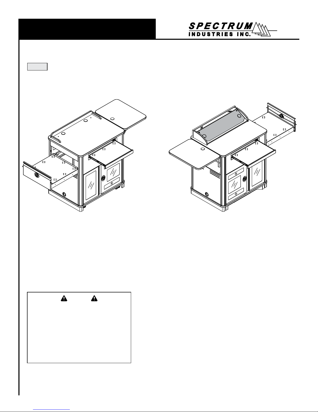
Media Manager Elite Lectern
55258
™
Media Manager Elite with surround,
left drawer, rack cube installed on right,
ip-up shelf on right
Important
Before using this product:
• Read this manual
• Comply with all safety and operating instructions
• Ensure all parts and correct quantities are included
Any parts damaged during shipment must be reported
within 5 days of receipt. To report information regarding
missing parts or damage, to purchase parts or accessories, or if you have any questions, please contact us.
Thank you for purchasing Spectrum products!
Media Manager Elite with overbridge,
right drawer, rack cube installed on left,
and toe kick, ip-up shelf on left
925 First Avenue, Chippewa Falls, WI 54729 USA
Spectrum Industries, Inc
800 235 1262
715 723 6750
www.spectrumfurniture.com
0118738R6 Page 1 of 15
Page 2
Important Safety and Care Instructions
• Read this owner’s manual before assembly or operation.
• Do not allow children to move the lectern.
• Proceed slowly and carefully when moving the lectern.
• For indoor use only. Do not install or store the lectern where it will be exposed
to moisture.
• Do not block the ventilation openings.
• Avoid uneven loading of the equipment into the lectern. Uneven weight
distribution could cause the lectern to tip when the lectern is moving.
• Do not allow anyone to sit, stand, or climb on the lectern.
• Use a damp, soft-cloth, or sponge, with mild soap or detergent solution to clean
dirty surfaces. Do not use harsh solvents or abrasives.
• This lectern is intended for institutional use. It does not have any user-
serviceable parts or user-maintenance requirements. If servicing is necessary,
please contact Spectrum Industries for assistance.
Warning - Relocating audio and/or video equipment to furniture not speci cally
designed to support audio and/or video equipment may result in death or
serious injury due to the furnishing collapsing or over turning onto a child.
Warning - Death or serious injury may occur when children climb on audio
and/or video equipment furniture. A remote control or toys placed on the
furnishing may encourage a child to climb on the furnishing and as a result the
furnishing may tip over on to the child.
Electrical Safety:
• Do not plug the power cord into an extension cord.
• Inspect power cords for damage before each use. Do not use power cords
that are damaged.
• Unplug power cord from electrical outlet by gripping the cord. Do not unplug
the power cord by pulling only on the cord.
• Do not step on, drive over, drag, or place objects on the power cord.
• For added safety, plug the lectern into a grounded outlet controlled by a GFI
(Ground Fault Interrupter) circuit breaker.
• Electrical devices are not toys. Children are often unaware of the hazards
associated with electrical devices. This lectern must always be used by
adults or with adult supervision.
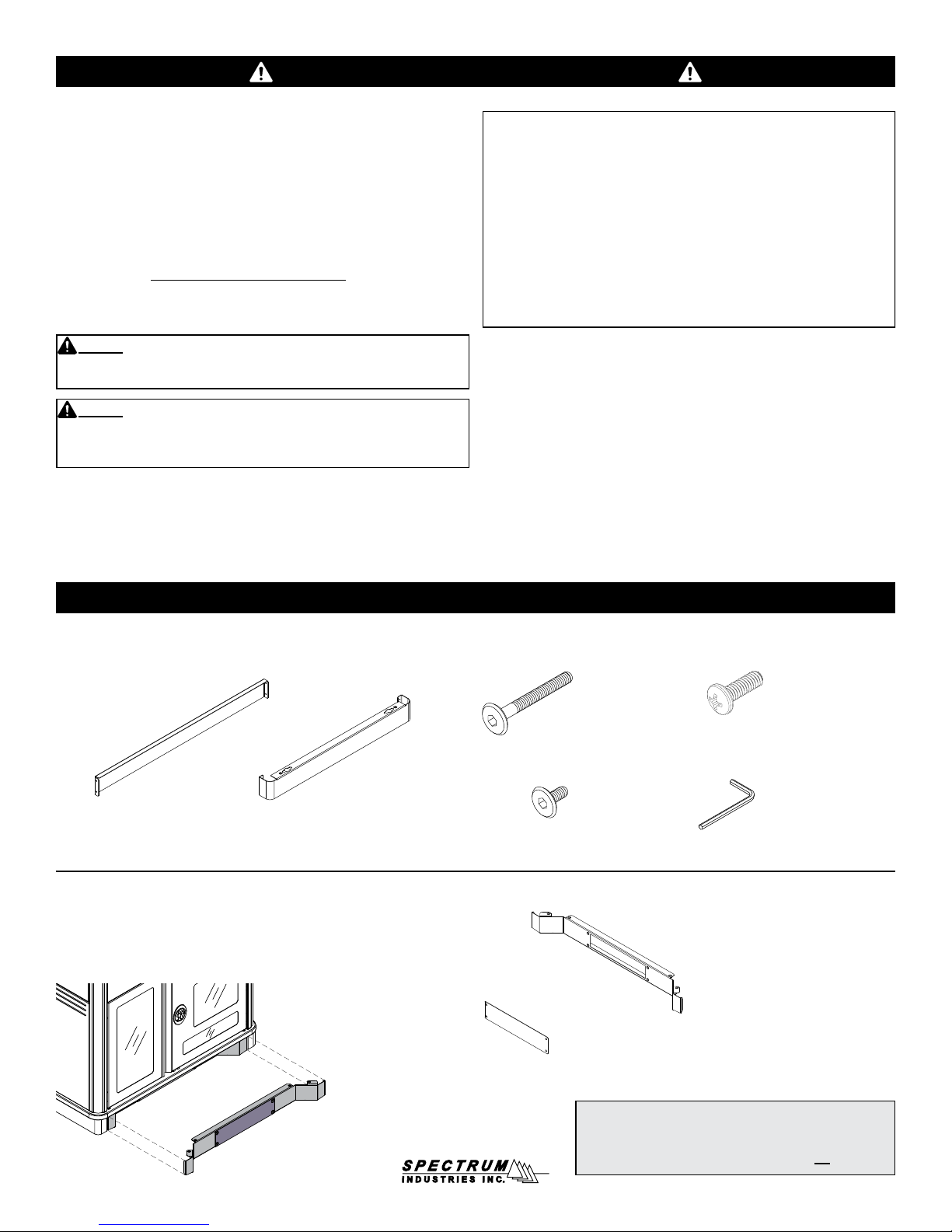
(1) 0118607
Audience-side skirt
Toe Kick
(included with select congurations)
(2) 0118608
Side skirt
Hardware
(6) 053310
1/4-20 x 40mm
JC bolts
(4) 052605
1/4-20 x 15mm
JC bolts
(1) 0118614
Toe Kick Plate
(4) 0100167
8-32 x 1/2” PH
Thread-cutting screw
(1) 025039
4mm Hex
wrench
(1) 0118613
Toe Kick
Note: If the toe kick will be anchored to the oor, (4) fasteners are required that will work with the 1/2” diameter holes
on the toe kick. Due to the wide variety of ooring materials
and conditions possible, anchor fasteners are not provided.
0118738R6 Page 2 of 15
Page 3
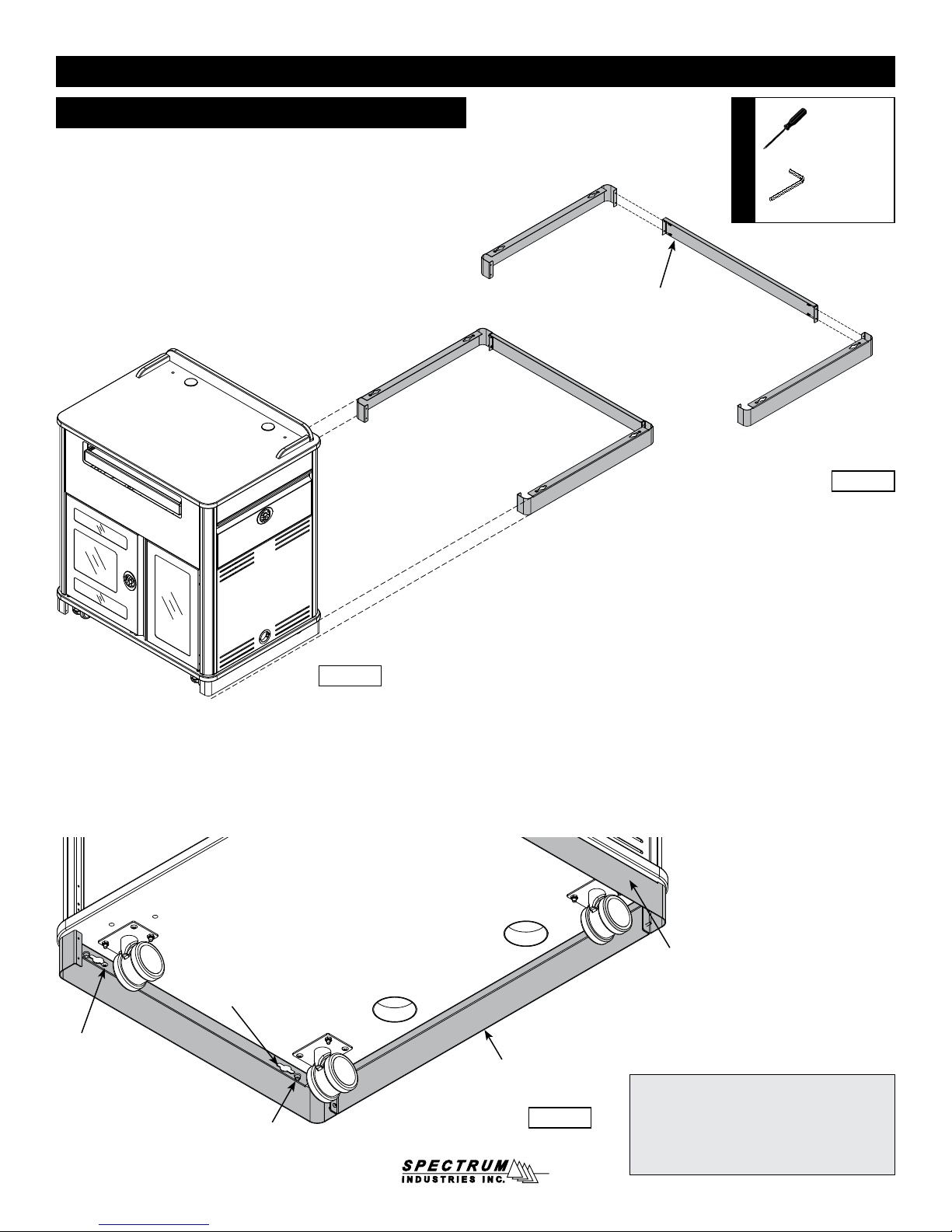
Assembly / Setup
1. Install 3-piece skirt
1. Attach the two side skirts to the audience-side skirt with (4)
8-32 x 1/2” PH Thread-cutting screws. Figure 1A.
2. Move lectern into position over the assembled skirt as
shown. Figure 1B.
Side skirt
Skirt Assembly
8-32 x 1/2” PH
Thread-cutting screws
(4 required)
Tools Required
Audience-side skirt
Phillips
screwdriver
4mm Hex
wrench
(included)
Side skirt
Figure 1A
Instructor-side
3. Hook the skirt keyhole slot at the end of each side skirt over the preinstalled #14 x 7/8” PHSM screw. Figure 1C.
4. From inside the lectern (on audience-side) , install (2) 1/4-20 x 40mm
JC bolts through the base panel to secure the assembled skirt, and
tighten securely.
Keyhole
slot
#14 x 7/8” PHSM
(pre-installed)
1/4-20 x 40mm JC bolt
(install from inside lectern)
Figure 1B
Assembled skirt
Figure 1C
1/4-20 x 40mm JC bolt
(install from inside lectern)
Note: The skirt is designed to be easily removable. It should be removed if the lectern
will be moved over long distances or thresholds to prevent damage to the skirt panels.
Do not tip lectern to remove or install!
0118738R6 Page 3 of 15
Page 4

Audience-side panel
The audience-side panel can be removed to access the rear portion of the rack
cube and lectern.
1. To remove the panel, open the document camera drawer fully.
Figure 2A.
2. Unscrew the (2) knobs inside the lectern behind the audience-side
panel and remove. Magnets are installed at the top corners of the
panel to prevent tipping. Figure 2B.
3. Carefully pull the top of the panel away from the lectern to release
the magnets, then lift the panel out. Figure 2C.
4. To replace the panel, insert the panel tabs back into base panel slots,
then tip the panel back up into position. Replace the knobs, and
tighten securely.
Tools
Required
Phillips
screwdriver
Knobs
Figure 2A
Open document
camera drawer
Magnet inside each
upper corner
Figure 2B
Audience-side
panel
Slots in base panel
Figure 2C
0118738R6 Page 4 of 15
Page 5
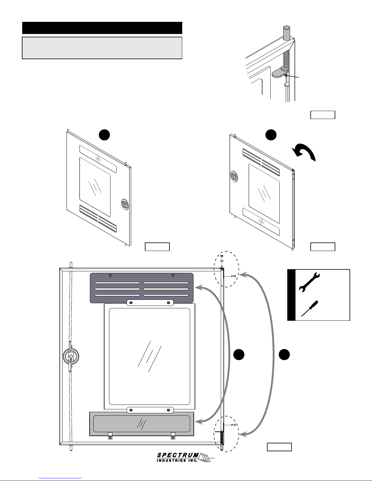
Quick-release doors
The doors can easily be removed for easier access using the quickrelease hinge lever located on the upper hinge pin of each door.
Figure 3A. To remove, lift the lever while lifting out the door.
The doors can be switched to be hinged from the left or right-side.
To switch the hinge side:
1. Remove the door using the quick-release lever. Figure 3B.
2. Rotate the door 180°. Figure 3C.
3. The vented panel should be located on the bottom of the door.
Switch the lower vented metal panel with the upper acrylic panel
(requires removing or loosening 8-32 nuts.) Figure 3D.
4. Switch the corner hinge components as shown and tighten securely.
5. Re-install the door.
1 2
Hinged on left
Quick-release
lever
Figure 3A
180°
Figure 3B
3 4
Hinged on right
Figure 3C
Tools Required
11/32” and
3/8” or
adjustable
wrench
Phillips
screwdriver
Figure 3D
0118738R6 Page 5 of 15
Page 6

Keyboard tray / drawer
Note: Can be used as a keyboard tray, or ipped and used as a drawer.
1. To ip, pull the tray out fully and locate the black plastic lever
on each slide. Figure 4.
2. Release the levers on the both slides while pulling the tray out.
3. Flip the tray over, re-align the slides, and push back in.
Keyboard Tray
Push here on both
slides to release
Figure 4
Optional rack cube
The removable rack cube (12RU) simplies installation and provides the ability to integrate equipment
remotely. The cube can be installed into the lectern at a later date. The cube also provides mounting
capabilities for multiple cooling fans if necessary. Compatible with most 4.75” cooling fans with 4.13”
mounting hole spacing (12 mounting locations available). Figure 5.
1. To remove the rack cube, open or remove the doors. Figure 5A.
2. Unscrew the #14 x 7/8” PHSM screw from the base, and slide out the cube. Figure 5.
• To move the rack cube to the other side of the lectern, all that is needed is to remove the (5)
bumper stops in the base panel with a 4mm hex wrench, and relocate them to the opposite side of
the base panel. The doors can easily be removed and switched using the quick-release levers.
Quick-
release
lever
Phillips
Tools
Required
Primary Door
(Removable-can be installed
on left or right-side)
screwdriver
Figure 5A
Secondary Door
(Removable-can be installed
on left or right-side)
(1) #14 x 7/8
PHSM to secure
cube to base
Figure 5
Removable Rack Cube
(Can be installed on left
or right-side)
0118738R6 Page 6 of 15
Page 7

Optional ip-up shelf
Upper mounting position
Lower mounting position
Release lever
(press here)
Figure 6B
CAUTION
Keep clear of pinch points during shelf movement.
Do not exceed 35 lb [15.9 kg] of weight on shelf.
19.25”W
Shelf grommet
Operation
The shelf will automatically lock into place when lifted into the
horizontal position with the levers released. To lower or ip-up the
shelf, press and hold the levers under each folding shelf bracket at the
same time while slowly lowering or raising the shelf. Do not exceed a
maximum of 35 lb of weight on the shelf. Do not move the unit while
the shelf is in the horizontal position.
Note: Power and communication wiring for document cameras, laptop
computers, and / or projectors placed on the ip-up shelf should be routed
on top of the audience-side of the shelf. Use of the shelf grommet hole for
wiring will result in pinching of the cords when the shelf is lowered.
[48.9 cm]
26”D
[66 cm]
Figure 6A
5.5”H
[14 cm]
0118738R6 Page 7 of 15
Page 8

Optional overbridge insert panel cutouts
1. Before you begin, refer to the panel dimensions in Figure 7B for
maximum recommended cutout sizes.
2. Identify the size and position (left, centered, or right) of each cutout
needed.
3. Identify the depth of your device to verify it will not interfere with the
worksurface or any other objects under the overbridge when the
panel is attached. Figure 7C.
4. When the cutout location(s) have been determined, locate and mark the
exact cutout area(s) on the panel with a pencil. Note: Using masking
tape on cut lines will minimize laminate chipping while cutting.
5. Carefully make the cutout(s) in the panel using a jigsaw or router.
6. Set the panel into the overbridge frame opening. Note: It may be
necessary in some cases to install the electronic device into the
panel before attaching the panel to the overbridge.
7. Secure with (2) 1/4-20 x 35mm JC bolts and tighten securely.
8. Install (2) 2” grommets.
Tools Required
4mm Hex
Wrench
(included)
Drill bit
Pencil Masking
Jigsaw or routerDrill
Measuring
Device
tape
1/4-20 x 35mm
JC bolt
(2 required)
Figure 7A
Overbridge
panel
Overbridge frame
2” grommet
Note: Blank overbridge panels require the customer to make necessary cutouts with a jigsaw
or router. This has a moderate difculty rating,
so experience and skill with tools is required.
Note: The overbridge panel is symmetrical. Rotating or ipping the
panel 180° and re-attaching to the overbridge will allow you to place the
cutout on the opposite side of the overbridge if necessary.
0118738R6 Page 8 of 15
Page 9

Max cutout area
2” Grommet2” Grommet
Figure 7B
Overbridge
Section View
Overbridge panel
Worksurface opening below
Note: The Overbridge Control Console™ has been designed
for many of the currently available controllers on the market,
however, modied cutouts should be reviewed by Spectrum
to ensure clearance of brackets, keyboard slides, or other
objects under the worksurface.
Contact Spectrum to specify cutout size(s) and location(s).
Cutouts can be made in the blank insert panel by the
customer after the lectern has been purchased, but are
only recommended within the cutout area shown.
Worksurface
Figure 7C
Note: The max cutout areas shown are general
recommendations only. The nal location of the cutout(s)
on the panel will be determined by:
• The size of the cutout(s)
• Location preference of each device (left, centered, right)
• The vertical depth of the installed device
• The available worksurface opening under the
overbridge on your specic Spectrum lectern.
0118738R6 Page 9 of 15
Page 10

Optional toe kick
1. Position the toe kick panel on the oor in the preferred nal lectern
location. Figure 8A.
2. Mark the (4) mounting hole locations onto the oor.
(The toe kick mounting holes are 1/2” dia.)
3. Drill suitable holes into the oor and anchor the toe kick with
appropriate fasteners.
4. At this point, wiring connections can be made under the lectern with
easier access to the base panel grommet holes.
(4) 1/2” mounting
holes for oor anchors
Tools
Required
Toe Kick Panel
4mm Hex
wrench
(included)
Note: If the toe kick will be anchored to the oor, (4) fasteners are
required that will work with the 1/2” diameter holes on the toe kick.
Due to the wide variety of ooring materials and conditions possible,
anchor fasteners are not provided.
5. Move lectern into position over the anchored toe kick. Figure 8B.
6. Align the (4) base panel mounting holes (instructor-side) with the
toe kick panel mounting holes.
7. Attach toe kick plate with (4) 1/4-20 x 15mm JC bolts.
Toe kick panel
anchored to
oor
Floor
Figure 8A
8. Open or remove both doors.
9. Install (4) 1/4-20 x 40mm JC bolts through the base
panel to secure, and tighten securely. Figure 8C.
1/4-20 x 40mm JC bolts
(4 required)
Toe Kick Plate
1/4-20 x 15mm JC bolt
(4 required)
Figure 8CFigure 8B
0118738R6 Page 10 of 15
Page 11

Caster operation
1. Lock the brake levers to lock movement of the casters.
(Two instructor-side casters only). Figure 9.
2. To resume operation, lift up on brake levers.
Skirt
Brake lever
Moving and parking the lectern
• Before moving, unplug and secure all power cords.
• Close and lock doors.
• Lower any ip-up shelves.
• Remove any items from the top of the worksurface.
• Unlock the casters.
• Push slowly and carefully. Do not move over uneven or irregular surfaces.
• Do not allow children to move.
• Lock the casters after moving.
• Do not park unit in areas of heavy trafc.
• Do not run power cords across hallways, classrooms, or areas where
they will be walked on.
When lectern is unattended:
• Do not leave in areas where children have access.
• Keep doors closed and locked.
• Keep casters locked.
Figure 9
Note: The skirt is designed to be easily removable. It should be removed
if the lectern will be moved over long distances or thresholds to prevent
damage to the skirt panels.
Do not tip lectern to remove or install!
0118738R6 Page 11 of 15
Page 12

Accessories
(Customer-installed when purchased separately)
12RU Rack Cube - 55197
• One rack cube can be installed
on the left or right side of the
Media Manager Elite Lectern
• Polyethylene slides on bottom for
easy removal
• Can be secured to base panel
• Cooling fan compatible
• Color: black
• Customer-installed
26”D
[66 cm]
19.25”W
[48.9 cm]
5.5”H
[14 cm]
Rack rail: 12RU front and rear
Dimensions:
Mounts for cooling fans:
Unit weight: 25 lb [11.4 kg]
Flip-Up Shelf - 55269
• Shelf hinges lock into place in the upright position
• Includes 2” grommet
• Two height positions available
• Customer-installed
Weight capacity: 35 lb [15.9 kg]
Dimensions: 19.25”W [48.9 cm] x 26”D [66 cm] x 1”H [2.54 cm]
Height positions
available:
Unit weight: 21 lb (9.5 kg)
Shipping weight: N/A
Note: Power and communication wiring for document cameras, laptop
computers, and/or projectors placed on the ip-up shelf should be routed
on top of the audience-side of the shelf. Use of the shelf grommet hole
for wiring will result in pinching of the cords when the shelf is folded.
19.125”W [48.58 cm] x 19.031”D [48.34 cm] x
21.25”H [53.97 cm]
Compatible with most 4.7” fans with 4.13” mounting
hole spacing (12 mounting locations available)
41”H [104.1 cm] (level with worksurface)
34”H [86.4 cm]
Customized Logo Panel - 55199
• Attaches to audience-side of lectern
• To get panel customized-contact Spectrum for details
• New logos require a rst time logo charge
• Customer-installed
Dimensions: 30”W [76.2 cm] x 12”H [30.48 cm]
Available logo area: 28”W [71.1 cm] x 10”H [25.41 cm]
Unit weight: 6 lb [2.7 kg]
Shipping weight: 8 lb [3.6 kg]
Logo area available
0118738R6 Page 12 of 15
Page 13

Overbridge Insert Panel
96507 - Blank panel
96507mod - Panel with cutout(s)
• Panel for overbridge version only (overbridge not available separately)
• Contact Spectrum to specify cutout size(s) and position(s)
• Includes two 2” [5.08 cm] grommets with covers
• Customer-installed
Dimensions: 33.25”W [84.5 cm] x 9”D [22.9 cm] x .79”H [2 cm]
Unit weight: N/A
Shipping weight: 8.5 lb [3.9 kg]
The 96507 Insert Panel is available to customers needing a
replacement panel or different cutouts for technology upgrades.
™
Cove
Power Module - 99044
• Two power receptacles
• Two USB charge ports
(not data-compatible)
• Thumbscrew clamps
• Requires worksurface cutout
• ETL listed
• Available in Black or Silver
• Customer-installed
Cutout required: 5.25”W [13.3 cm] x 2”D [5.1 cm]
Power cord: 9’ [274 cm] with 90° at plug with 45° rotation
Power receptacles: 12A, 120 VAC spill-resistant
USB charging ports: 2.1A (10.5W)
Dimensions: 6”W [15.2 cm] x 2.5”D [6.35 cm] x 3.18”H [8.1 cm]
Unit weight: 2 lb [.9 kg]
Shipping weight: 2.29 lb [1 kg]
Toe Kick Panel Kit - 55198
• Attaches to oor and lectern when mobility is not
necessary or desired (oor fasteners not included)
• Conceals casters
• Includes access panel
• Customer-installed
• Unit weight: N/A
• Shipping weight: 12 lb [5.4 kg]
Skirt
Toe Kick Panel
0118738R6 Page 13 of 15
Page 14

Universal Cord Reel Kit - 99037
• Includes universal mounting bracket
• Mounts inside lectern to base panel
• Adjustable ball stop and releasable cord-locking
ratchet holds the cord at any length up to 15’
• cUL listed
• Customer-installed
Power cord: 15’ nominal, 12 AWG retractable power cord
Power receptacles: • Molded 3-prong male plug with 15A breaker
Universal mounting
bracket
Unit weight: 10 lb [4.5 kg]
Shipping weight: 10.8 lb [4.9 kg]
The cord reel is intended to provide temporary access to electrical outlets for
Spectrum mobile lecterns. Check local electrical codes prior to installation.
and reset button
• Tri-tap (3-outlet) receptacle
• 16-gauge steel
• Black powder coat
• Includes mounting screws
Rack cube
(Available positions on
base with rack cube)
See spectrumfurniture.com for the latest
accessories and detailed warranty information.
0118738R6 Page 14 of 15
Page 15

Warranty
DESIGNED AND ASSEMBLED IN
CHIPPEWA FALLS
WISCONSIN.USA
WE WILL MAKE IT RIGHT FOR YOU!
Spectrum is committed to provide complete customer satisfaction. Each of our products is manufactured from the best materials available and each
product is stringently monitored throughout the production process through our P.A.C.E. program (Product Assurance to meet Customer Expectations).
We expressly warrant that Spectrum products will be of good quality and workmanship and free from defect for the period set out in the warranty table below
from the date of delivery. This warranty shall not apply to defects or damage resulting from misuse, abuse, neglect, improper care, modifi cation or repair not
authorized by Spectrum, or any other cause outside the control of Spectrum. Spectrum will, at its sole option, either repair or replace the defective product.
This warranty is exclusive; no other warranty, written or oral, is expressed or implied. This warranty is given by Spectrum to Buyer and to no other per-
son or legal entity. No Spectrum dealer, distributor, agent or employee is authorized to make any modifi cation or addition to this warranty.
NOTWITHSTANDING ANYTHING TO THE CONTRARY, SPECTRUM WILL NOT UNDER ANY CIRCUMSTANCES BE LIABLE FOR INDIRECT OR LIQUIDATED DAMAGES, INCLUDING CONSEQUENTIAL, INCIDENTAL AND SPECIAL DAMAGES. IN NO EVENT SHALL SPECTRUM’S LIABILITY, WHETHER
UNDER CONTRACT OR WARRANTY, IN TORT OR OTHERWISE, EXCEED THE PURCHASE PRICE RECEIVED BY SPECTRUM FOR THE PRODUCT AT
ISSUE AND “RECALL ACTION” EXPENSES. SPECTRUM SHALL NOT BE SUBJECT TO ANY OTHER OBLIGATIONS OR LIABILITIES, WHETHER ARISING OUT OF BREACH OF CONTRACT, WARRANTY, TORT (INCLUDING NEGLIGENCE AND STRICT LIABILITY) OR OTHER THEORIES OF LAW, WITH
RESPECT TO PRODUCTS SOLD OR SERVICES RENDERED BY SPECTRUM, OR ANY UNDERTAKINGS, ACTS OR OMISSIONS RELATING THERETO.
Our Customer Service Department is ready to provide immediate attention to any questions, comments or concerns. They are available to answer your calls
Monday through Friday from 7 am to 5 pm CST. In addition your product comments or concerns are welcome via e-mail at: spectrum@spectrumfurniture.com.
Warranty Table
Item
Adjustable Crank / Electric Desk Legs
Flat Panel Desk Gas Cylinders
Chairs
• Adjustable Height Chair Parts – including frames, gas
cylinders, wood and plastic parts, control handles, casters
• Adjustable Height Chair Upholstery
• In-Stock Upholstery
• Graded-In Fabrics and Customer Owned Material
Height Adjustable Columns and Lifts
General Use Casters
Electrical (including timers and LINAK actuators) • 2 Years
Keyboard / Mouse Trays • 1 Year
Flat Panel Monitor Arms
• Flat Panel Monitor Arm – General Parts
• Flat Panel Monitor Arm – Gas Cylinders
Desks and Lecterns
• Computer Desk Chassis
• Cart Chassis
• Lectern Chassis
Warranty Period
effective 1/1/2015
• 1 Year
• 7 Years
• 2 Years
• 2 Years
• No Warranty
• 1 Year
• 5 Years
• 2 Years
• 10 Years
925 FIRST AVENUE, CHIPPEWA FALLS, WI 54729 / 800-235-1262 / 715-723-6750 / WWW.SPECTRUMFURNITURE.COM
© 2016 Spectrum Industries Inc., All rights reserved.
8
0118738R6 Page 15 of 15
 Loading...