


OMPLTV4250.book Page i Thursday, February 16, 2006 10:22 AM
PLTV-4250
42" Liquid Crystal Display
User’s Manual

OMPLTV4250.book Page ii Thursday, February 16, 2006 10:22 AM
Protron PLTV-4250 Liquid Crystal Display User’s Manual.
© 2006 Protron Digital Corporation. All rights reserved.
Under copyright law, this manual may not be reproduced in any form, in whole or in part, without the prior written consent of Protron Digital Corporation.
Disclaimer
Protron Digital Corporation has reviewed this manual and provides it only as a guide to operation. All statements, technical information, and recommendations in this manual and in any guides or related documents are believed reliable, but the accuracy and completeness thereof are not guaranteed or warranted, and they are not intended to be, nor should they be understood to be, representations or warranties concerning the products described.
Specifications are subject to change without notice.
Trademarks
Protron is a trademark of Prosonic Group Corporation.
Protron Digital Corporation
2133 S. Green Privado
Ontario, CA 91761
Printed in China

OMPLTV4250.book Page i Thursday, February 16, 2006 10:22 AM
Important Safety Instructions
1.Read these instructions.
2.Keep these instructions.
3.Heed all warnings.
4.Follow all instructions.
5.Do not use this apparatus near water.
6.Clean only with a dry cloth.
7.Do not block any ventilation openings. Install in accordance with the manufacturer's instructions.
8.Do not install near any heat sources such as radiators, heat registers, stoves, or other apparatuses (including amplifiers) that produce heat.
9.Do not defeat the safety purpose of the polarized or grounding-type plug. A polarized plug has two blades, one wider than the other.
A grounding-type plug has two blades and a third grounding prong.
The wide blade or the third prong are provided for your safety. If the provided plug does not fit into your outlet, consult an electrician for replacement of the obsolete outlet.
10.Protect the power cord from being walked on or pinched, particularly at plugs, convenience receptacles, and the point where they exit from the apparatus.
11.Only use attachments/accessories specified by the manufacturer.
12.Use only with the cart, stand, tripod, bracket, or table specified by the manufacturer or sold with the apparatus. When a cart is used, use caution when moving the cart/apparatus combination to avoid injury from tip-over.
13.Unplug this apparatus during lightning storms or when unused for
long periods of time.
14.Refer all servicing to qualified service personnel. Servicing is required when the apparatus has been damaged in any way, such as when the power supply cord or plug is damaged, liquid has been spilled or objects have fallen into the apparatus, the apparatus has been exposed to rain or moisture, the apparatus does not operate normally, or the apparatus has been dropped.
15.To reduce the risk of fire or electric shock, do not expose this appliance to rain or moisture.
16.Do not expose apparatus to dripping or splashing and do not place objects filled with liquid on the apparatus.
17.Only use apparatus with battery specified by manufacturer.
i
OMPLTV4250.book Page ii Thursday, February 16, 2006 10:22 AM
Product Cautions
TO PREVENT POSSIBLE DANGER, ELECTRIC SHOCK, AND OTHER INJURIES WHEN HANDLING YOUR DISPLAY, PLEASE BE AWARE OF OF ALL WARNINGS AND SAFETY PRECAUTIONS LISTED BELOW.
Never spill any liquid of any kind on the display.
Never insert anything into the display, where objects can come into contact with high voltage nodes or damage internal components.
Do not attempt to service the display yourself. Opening or removing covers exposes high voltage nodes and other hazards. Refer all servicing to qualified service personnel.
Do not touch the display or antenna during thunderstorms. Unplug the display during thunderstorms, or if it will not be used for extended periods. Failure to do so may result in electric shock or fire.
Before cleaning the display, unplug it from the wall. Use a damp cloth for cleaning. Never use liquid or aerosol cleaners.
To prevent overheating and ensure reliable operation, place the display only in a well ventilated location. Avoid cramped or inadequately ventilated locations. Place the display at least 10 cm (4") from walls or other objects. Always keep the vent clean. Never place the display upside down.
Note: Read all safety and operating instructions before operating your new display.
ii

OMPLTV4250.book Page iii Thursday, February 16, 2006 10:22 AM
Conformity and Compliance
FCC Compliance Statement
This equipment has been tested and found to comply with the limits for a Class B digital device, pursuant to Part 15 of the FCC Rules. These limits are designed to provide reasonable protection against harmful interference when the equipment is operated in a residential installation. This equipment generates, uses, and can radiate radio frequency energy and, if not installed and used in accordance with the instructions, may cause harmful interference to radio communications. However, there is no guarantee that interference will not occur in a particular installation. If this equipment does cause harmful interference to radio or television reception (this can be determined by turning the device off and on), the user is encouraged to try to correct the interference by one or more of the following measures:
•Reorient or relocate the receiving antenna.
•Increase the separation between the equipment and the receiver.
•Connect the equipment to an outlet on a circuit different from that to which the receiver is connected.
•Consult the dealer or an experienced radio/TV technician for help.
Caution:
To comply with the limits for an FCC Class B computing device, the user should use the shielded signal cable and power cord supplied with the unit. The FCC warns that changes or modifications of the unit not expressly approved by the party responsible for compliance could void the user’s authority to operate the equipment.
Radio Frequency Interference Statement
Warning:
This is a Class B product. In a domestic environment this product may cause radio interference, in which case the user may be required to take adequate measures.
Canadian DOC Notice for Class B Computing Devices
This digital apparatus does not exceed the Class B limits for radio noise emissions from a digital apparatus as set out in the Radio Interference Regulations of the Canadian Department of Communications.
CE Marking and Declaration of Conformity
This device complies with the requirements of related European standards, which include the following:
•Emission: EN 55022, EN 61000-3-2, EN 61000-3-3
•Immunity: EN 50082-1
•Safety: EN 60950 Low-Voltage Directive (73/23/EEC)
iii

OMPLTV4250.book Page iv Thursday, February 16, 2006 10:22 AM
iv

OMPLTV4250.book Page v Thursday, February 16, 2006 10:22 AM
Table of Contents
Introduction . . . . . . . . . . . . . . . . . . . . . . . . . . . . . . . . . . . . . . . . . . . . . . . . . . . . . . . . . . . . . . . . . . . . . 1 Features . . . . . . . . . . . . . . . . . . . . . . . . . . . . . . . . . . . . . . . . . . . . . . . . . . . . . . . . . . . . . . . . . . . . . 1 Unpacking Your New Display . . . . . . . . . . . . . . . . . . . . . . . . . . . . . . . . . . . . . . . . . . . . . . . . . . . . . . . 2 Setting Up the Display. . . . . . . . . . . . . . . . . . . . . . . . . . . . . . . . . . . . . . . . . . . . . . . . . . . . . . . . . . . . . 3 Connecting a Digital TV (HDTV) Signal . . . . . . . . . . . . . . . . . . . . . . . . . . . . . . . . . . . . . . . . . . . . 3 Connecting an Analog TV Signal . . . . . . . . . . . . . . . . . . . . . . . . . . . . . . . . . . . . . . . . . . . . . . . . . 4 Connecting Composite Video Devices . . . . . . . . . . . . . . . . . . . . . . . . . . . . . . . . . . . . . . . . . . . . . 4 Connecting S-Video Devices . . . . . . . . . . . . . . . . . . . . . . . . . . . . . . . . . . . . . . . . . . . . . . . . . . . . . 5 Connecting Component Video Devices . . . . . . . . . . . . . . . . . . . . . . . . . . . . . . . . . . . . . . . . . . . . 5 Connecting HDMI Devices . . . . . . . . . . . . . . . . . . . . . . . . . . . . . . . . . . . . . . . . . . . . . . . . . . . . . . 6 Connecting to an Audio System. . . . . . . . . . . . . . . . . . . . . . . . . . . . . . . . . . . . . . . . . . . . . . . . . . 6 Connecting to a Video Input System . . . . . . . . . . . . . . . . . . . . . . . . . . . . . . . . . . . . . . . . . . . . . . 7 Connecting a PC . . . . . . . . . . . . . . . . . . . . . . . . . . . . . . . . . . . . . . . . . . . . . . . . . . . . . . . . . . . . . . 7 Operating the Display . . . . . . . . . . . . . . . . . . . . . . . . . . . . . . . . . . . . . . . . . . . . . . . . . . . . . . . . . . . . . 9 Turning the Display On and Off. . . . . . . . . . . . . . . . . . . . . . . . . . . . . . . . . . . . . . . . . . . . . . . . . . 9 Selecting the Video and Audio Source . . . . . . . . . . . . . . . . . . . . . . . . . . . . . . . . . . . . . . . . . . . . 9 Adjusting the Volume. . . . . . . . . . . . . . . . . . . . . . . . . . . . . . . . . . . . . . . . . . . . . . . . . . . . . . . . . . 9 Selecting the Television Channel . . . . . . . . . . . . . . . . . . . . . . . . . . . . . . . . . . . . . . . . . . . . . . . . . 9 Accessing the On-Screen Display . . . . . . . . . . . . . . . . . . . . . . . . . . . . . . . . . . . . . . . . . . . . . . . . 10 Using Your Display for the First Time. . . . . . . . . . . . . . . . . . . . . . . . . . . . . . . . . . . . . . . . . . . . . . . . 11 Setting up Digital Television Channels . . . . . . . . . . . . . . . . . . . . . . . . . . . . . . . . . . . . . . . . . . . 11 Setting up Analog Television Channels . . . . . . . . . . . . . . . . . . . . . . . . . . . . . . . . . . . . . . . . . . . 11 Using the Remote Control. . . . . . . . . . . . . . . . . . . . . . . . . . . . . . . . . . . . . . . . . . . . . . . . . . . . . . . . . 13 Replacing the Remote Batteries. . . . . . . . . . . . . . . . . . . . . . . . . . . . . . . . . . . . . . . . . . . . . . . . . 15 Configuring the Display . . . . . . . . . . . . . . . . . . . . . . . . . . . . . . . . . . . . . . . . . . . . . . . . . . . . . . . . . . 16 Video . . . . . . . . . . . . . . . . . . . . . . . . . . . . . . . . . . . . . . . . . . . . . . . . . . . . . . . . . . . . . . . . . . . . . . 17 Audio . . . . . . . . . . . . . . . . . . . . . . . . . . . . . . . . . . . . . . . . . . . . . . . . . . . . . . . . . . . . . . . . . . . . . . 17 Miscellaneous . . . . . . . . . . . . . . . . . . . . . . . . . . . . . . . . . . . . . . . . . . . . . . . . . . . . . . . . . . . . . . . 18 TV . . . . . . . . . . . . . . . . . . . . . . . . . . . . . . . . . . . . . . . . . . . . . . . . . . . . . . . . . . . . . . . . . . . . . . . . . 22 PC . . . . . . . . . . . . . . . . . . . . . . . . . . . . . . . . . . . . . . . . . . . . . . . . . . . . . . . . . . . . . . . . . . . . . . . . . 22 DTV. . . . . . . . . . . . . . . . . . . . . . . . . . . . . . . . . . . . . . . . . . . . . . . . . . . . . . . . . . . . . . . . . . . . . . . . 23
Troubleshooting . . . . . . . . . . . . . . . . . . . . . . . . . . . . . . . . . . . . . . . . . . . . . . . . . . . . . . . . . . . . . . . . 26 Support Information . . . . . . . . . . . . . . . . . . . . . . . . . . . . . . . . . . . . . . . . . . . . . . . . . . . . . . . . . . 27 Specifications . . . . . . . . . . . . . . . . . . . . . . . . . . . . . . . . . . . . . . . . . . . . . . . . . . . . . . . . . . . . . . . . . . . 28 General . . . . . . . . . . . . . . . . . . . . . . . . . . . . . . . . . . . . . . . . . . . . . . . . . . . . . . . . . . . . . . . . . . . . 28 Picture-in-Picture Combinations. . . . . . . . . . . . . . . . . . . . . . . . . . . . . . . . . . . . . . . . . . . . . . . . . 29 Supported VGA Modes . . . . . . . . . . . . . . . . . . . . . . . . . . . . . . . . . . . . . . . . . . . . . . . . . . . . . . . . 29 Limited Warranty. . . . . . . . . . . . . . . . . . . . . . . . . . . . . . . . . . . . . . . . . . . . . . . . . . . . . . . . . . . . . . . . 30
v

OMPLTV4250.book Page vi Thursday, February 16, 2006 10:22 AM
vi

OMPLTV4250.book Page 1 Thursday, February 16, 2006 10:22 AM
Introduction
Congratulations on purchasing your new Protron Liquid Crystal Display!
You can use your new display as a television, in a home theater system, or even as a computer monitor. With HDMI, component, composite, and S-Video video inputs, you can connect numerous devices to your display, including DVD players, VCRs, HDTV receivers, video game systems, camcorders, and so on. And with video and audio output, you can connect your display to a home stereo system with a subwoofer, or even record what is displayed on the screen.
The built-in HDTV tuner allows you to simply connect a standard HDTV antenna to enjoy the clarity and brilliance of modern digital television.
The progressive scan HDMI and component video inputs on your display give you the highest quality video available, allowing you to enjoy crystal-clear DVDs and other media.
Features
•42" viewable display area
•1366 × 768 resolution
•Built-in HDTV tuner with coaxial input
•Analog TV tuner with coaxial input
•HDMI audio/video input
•2 progressive scan component video inputs
•3 composite video inputs
•S-Video input with optical audio input
•6 audio inputs, one for each video input
•Composite video output
•Audio output with subwoofer output
•Surround sound simulation
•VGA computer video input
•1/8" stereo audio input jack for computer audio
•VESA DPMS-compliant power saving—automatically turns off the display after a configurable period of inactivity
•Windows 95/98/2000/XP Plug and Play compliant
•Conforms to VESA standards and supports the DDC1 and DDC2B specifications
•Wide viewing angle
•Versatile, functional, and user-friendly On-Screen Display (OSD)
1
OMPLTV4250.book Page 2 Thursday, February 16, 2006 10:22 AM
Unpacking Your New Display
Before using your new display, you should unpack the contents of the box and check to make sure everything is present and undamaged.
To unpack the display:
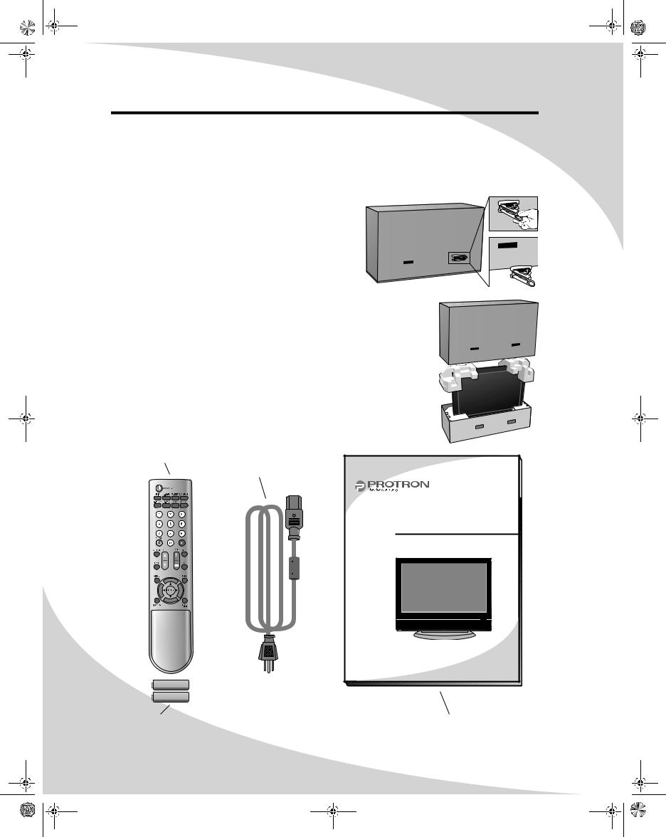
1. Using the four handles at the bottom of the box, set the box upright near the intended display location.
2. Remove the plastic insert from the right front handle.
3. Lift the top of the box off.
4. Remove the accessories box from behind the display and set it aside.
5. Lift the display out of the box.
6. Remove the pads and set the display aside.
The accessories box should contain the items indicated below. If any items are missing or damaged, contact the seller immediately.
Remote Control
Power Cord
PLTV-4250 |
42" Liquid Crystal Display |
User’s Manual |
2 × AAA Battery |
User's Manual |
2
OMPLTV4250.book Page 3 Thursday, February 16, 2006 10:22 AM
Setting Up the Display
The display requires a stable, level, and clean surface near a power outlet, 10 cm (4") away from walls or other large objects. The rear ventilation grid should be unobstructed, and the display should not be exposed to water or heat. Before setting up the display, prepare such a space.
To set up the display:
1.Remove the power cord from the accessories box, insert the appropriate end into the power (AC IN) connector on the bottom of the display, and then
insert the other end into a free power outlet.
2.Turn on the power switch on the bottom of the display.
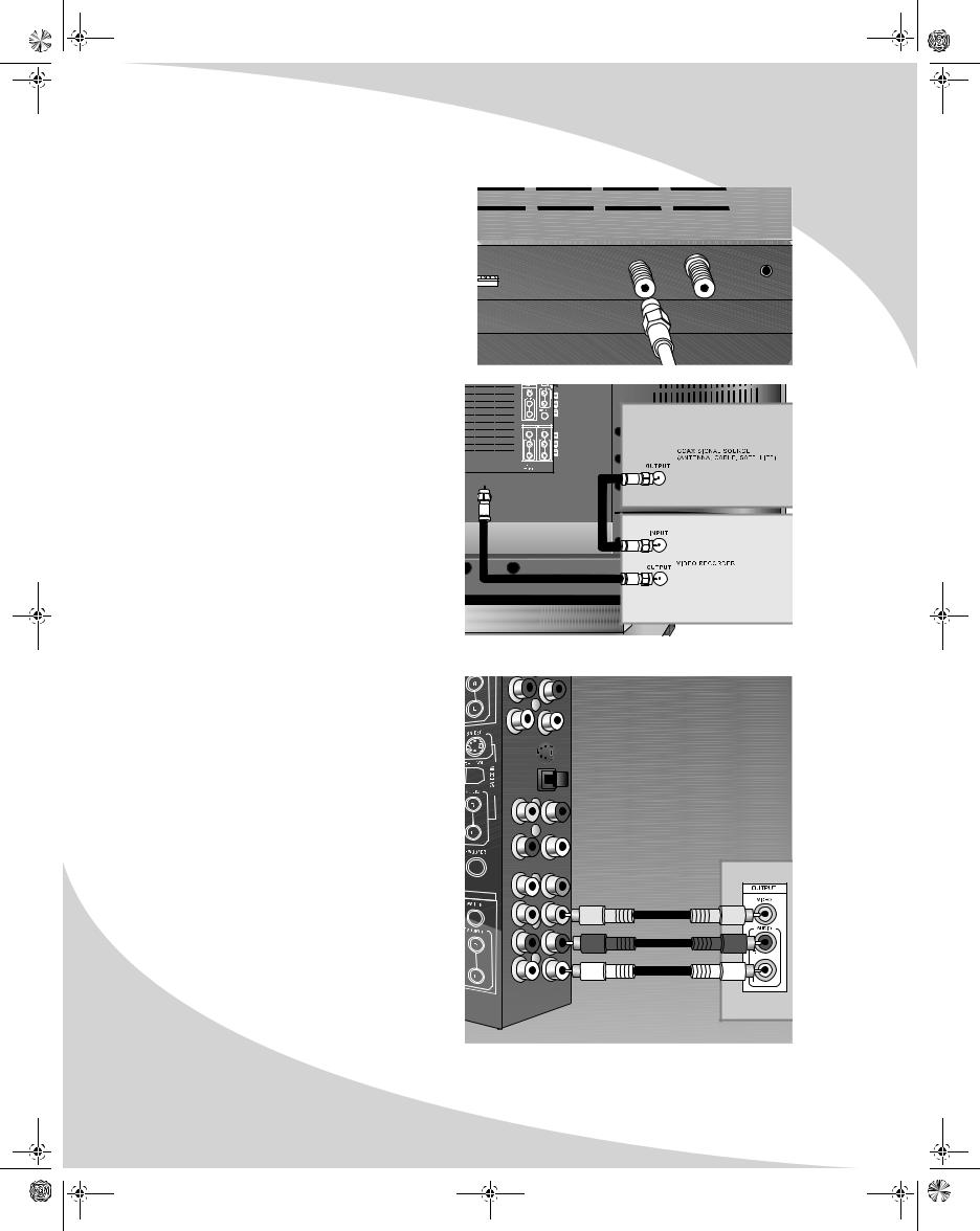
Connecting a Digital TV (HDTV) Signal
To connect an HDTV signal source to the display, connect a coaxial cable between the ATSC input and the TV signal source.
NTSC |
ATSC |
PC |
AUDIO IN |
3
OMPLTV4250.book Page 4 Thursday, February 16, 2006 10:22 AM
Setting Up the Display |
|
|
|
|
Connecting an Analog TV Signal |
|
|
|
|
An analog TV signal may come from a cable |
|
|
|
|
box, satellite receiver, antenna, or similar |
|
|
|
|
device. |
|
NTSC |
ATSC |
PC |
|
AUDIO IN |
|||
To connect an analog TV signal source to the |
|
|
|
|
display, connect a coaxial cable between the |
|
|
|
|
NTSC input and the TV signal source (for |
|
|
|
|
example, a cable box, satellite receiver, or |
|
|
|
|
antenna). |
|
|
|
|
Note: If you would like to be able to record |
|
|
|
|
the TV signal with a VCR, DVD |
|
|
|
|
recorder, or similar device, connect |
|
|
|
|
the TV signal source to the input of |
|
|
|
|
the recording device with one cable, |
NTSC |
ATSC |
|
|
then connect the output of the |
|
|
|
|
recording device to the NTSC jack on |
|
|
|
|
the display with another cable. |
|
|
|
|
Connecting Composite Video Devices
Many video devices, such as VCRs, DVD players, video game systems, and camcorders, have composite video outputs. Composite video uses one RCA cable to transmit video information and generally provides lower quality than S-Video, component video, and HDMI (see below).
To connect a composite video source to the display:
1. Using an RCA cable, connect the composite video output (yellow) on the source device to the corresponding jack in one of the three composite video blocks on the display (AV 1 IN, AV 2 IN, or AV 3 IN).
2. Using two other RCA cables, connect the right (red) and left (white) audio outputs on the source to the corresponding jacks in the same composite video block used above.
4

OMPLTV4250.book Page 5 Thursday, February 16, 2006 10:22 AM
Setting Up the Display
Connecting S-Video Devices
Many video devices that have composite video outputs also have S-Video outputs. S-Video uses a single four-wire cable to transmit video information. Two of the wires are used to transmit video. Because it splits the video signal into two components, S-Video generally provides higher quality than composite video, but lower quality than component video and HDMI (see below).
Note: The pins used in S-Video connectors are somewhat fragile. Take care to avoid bending the pins, as a bent or broken pin can cause loss of color information or total signal loss.
To connect an S-Video source to the display:
1. Using an S-Video cable, connect the S- Video output on the source device to the S-Video jack on the display.
2. Using two RCA cables, connect the right (red) and left (white) audio outputs on the source to the corresponding jacks in the S-Video block on the display.
Connecting Component Video Devices
High-quality video devices, such as HDTV receivers and high-end DVD players, have component video outputs. Component video uses three RCA connections to transmit video information. Because the information is split into three signals, component video offers higher quality than composite video and S-Video.
To connect a component video source
to the display:
1. Using three RCA cables, connect the  three component video outputs to the corresponding jacks in one of the two
 component video blocks on the display.
2. Using two other RCA cables, connect the right (red) and left (white) audio outputs on the source to the corresponding jacks in the same component video block used above.
R |
L |
5
OMPLTV4250.book Page 6 Thursday, February 16, 2006 10:22 AM
Setting Up the Display
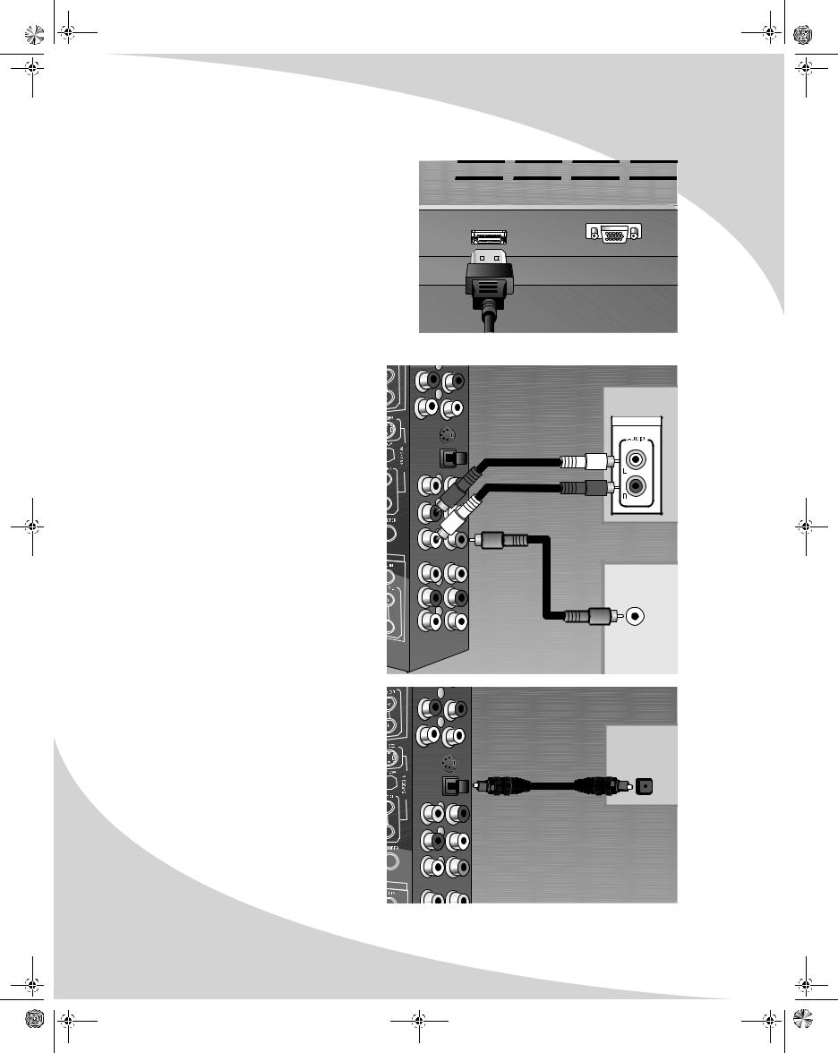
Connecting HDMI Devices
The highest-quality video devices have HDMI |
|
|
outputs. An HDMI cable carries progressive scan |
|
|
video of the highest quality. |
HDMI |
PC-VGA |
To connect an HDMI signal source to the display, use an HDMI cable to connect the source device to the HDMI input on the bottom of the display.
Connecting to an Audio System
Your display has audio outputs that may be used to play the display’s audio on a peripheral system, such as a stereo system or a home theater system. In addition, there is a subwoofer output that can be connected to a powered (amplified) subwoofer to fill out the bass.
To connect the display to an audio system:
1.Using two RCA cables, connect the right (red) and left (white) audio outputs in the output block on the display (AV OUT) to the corresponding inputs on your audio system.
2.(OPTIONAL) If you have a powered (amplified) subwoofer, connect a third RCA cable from the SUBWOOFER output on the display to the subwoofer’s (or amplifier’s) input.
To listen to the high-quality digital audio of an HDTV transmission, instead connect the OPTICAL output to your stereo system using an optical digital cable.
STEREO |
SYSTEM |
AUDIO IN |
POWERED SUBWOOFER
AUDIO IN
STEREO
SYSTEM
OPTICAL DIGITAL AUDIO INPUT
6
 Loading...