

Page 1
Das verknüpfte Bild kann nicht angezeigt werden. Möglicherweise wurde die Datei verschoben, umbenannt oder gelöscht. Stellen Sie sicher, dass die Verknüpfung auf die korrekt
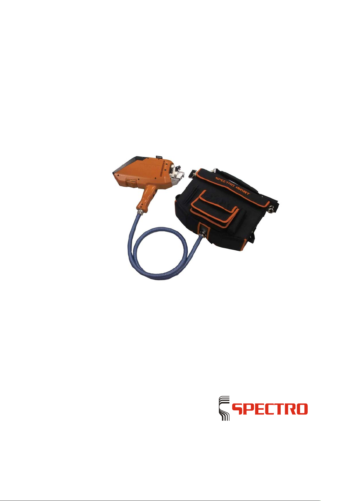
SPECTRO iSORT
Mobile Spectrometer for Metal
Analysis
Original operating instructions
Page 2

Das verknüpfte Bild kann nicht angezeigt werden. Möglicherweise wurde die Datei verschoben, umbenannt oder gelöscht. Stellen Sie sicher, das
Page 3

Unit description
SPECTRO iSORT
— 23.08.2013 —
3
Tabl e of Conten t s
1 Unit description ................................................................................................... 5
1.1 Function .............................................................................................................................. 5
1.2 Overview ............................................................................................................................. 5
1.3 Battery pack ........................................................................................................................ 6
1.3.1 Technical data ....................................................................................................... 6
1.3.2 Handling ................................................................................................................ 6
2 Safety .................................................................................................................. 7
2.1 User information .................................................................................................................. 7
2.2 Intended use ....................................................................................................................... 7
2.3 Prohibited operating conditions .......................................................................................... 8
2.4 Residual risk ....................................................................................................................... 8
3 Technical data................................................................................................... 10
4 Transport/Use ................................................................................................... 11
4.1 Dimensions and weight ..................................................................................................... 11
4.2 Transport ........................................................................................................................... 11
4.3 Use .................................................................................................................................... 12
5 Operation .......................................................................................................... 13
5.1 Overview of controls ......................................................................................................... 13
5.2 Displays ............................................................................................................................ 14
5.2.1 Sample probe ...................................................................................................... 14
5.2.2 PDA screen ......................................................................................................... 15
5.3 Preparing the unit for operation ........................................................................................ 16
5.4 Switching the unit on ......................................................................................................... 16
5.5 Switching the unit off ......................................................................................................... 17
5.6 Carrying out the measurement ......................................................................................... 17
5.6.1 Preparing the measurement ................................................................................ 17
5.6.2 Measuring ............................................................................................................ 18
•
Example of measurement: Approximate analysis ............................................... 18
•
Example measurement approximate analysis with “fingerprint” .......................... 19
•
Example of measurement: Sorting ...................................................................... 19
•
Standardization of measuring unit (ICALization) ................................................. 20
5.7 Replacing parts of sample probe ...................................................................................... 21
5.7.1 Sample probe parts overview .............................................................................. 21
5.7.2 Changing the adapter .......................................................................................... 22
5.7.3 Changing the electrode ....................................................................................... 23
6 Maintenance ..................................................................................................... 24
6.1 Maintenance schedule ...................................................................................................... 24
6.2 Cleaning the adapter......................................................................................................... 25
6.3 Cleaning the light inlet windows of the sample probe and of the adapter ........................ 25
Page 4

—
4 SPECTRO iSORT —
23.08.2013
6.4 Changing/cleaning the air filter (probe) ............................................................................. 26
6.5 Cleaning/sharpening the electrodes ................................................................................. 26
7 Troubleshooting ................................................................................................ 27
8 Spare parts and consumables .......................................................................... 28
Page 5
Unit description
SPECT
RO iSORT — 23.08.2013 —
5
1 Unit description
1.1 Function
The sample probe evaporates sample material by means of arc discharge. In this
process, the released atoms and ions are stimulated to emit radiation. An optical
fiber directs this radiation to the optical system. Here the radiation is evaluated.
Data are already stored in the unit's memory. The measured values are compared
with these data. The results are displayed on the screen.
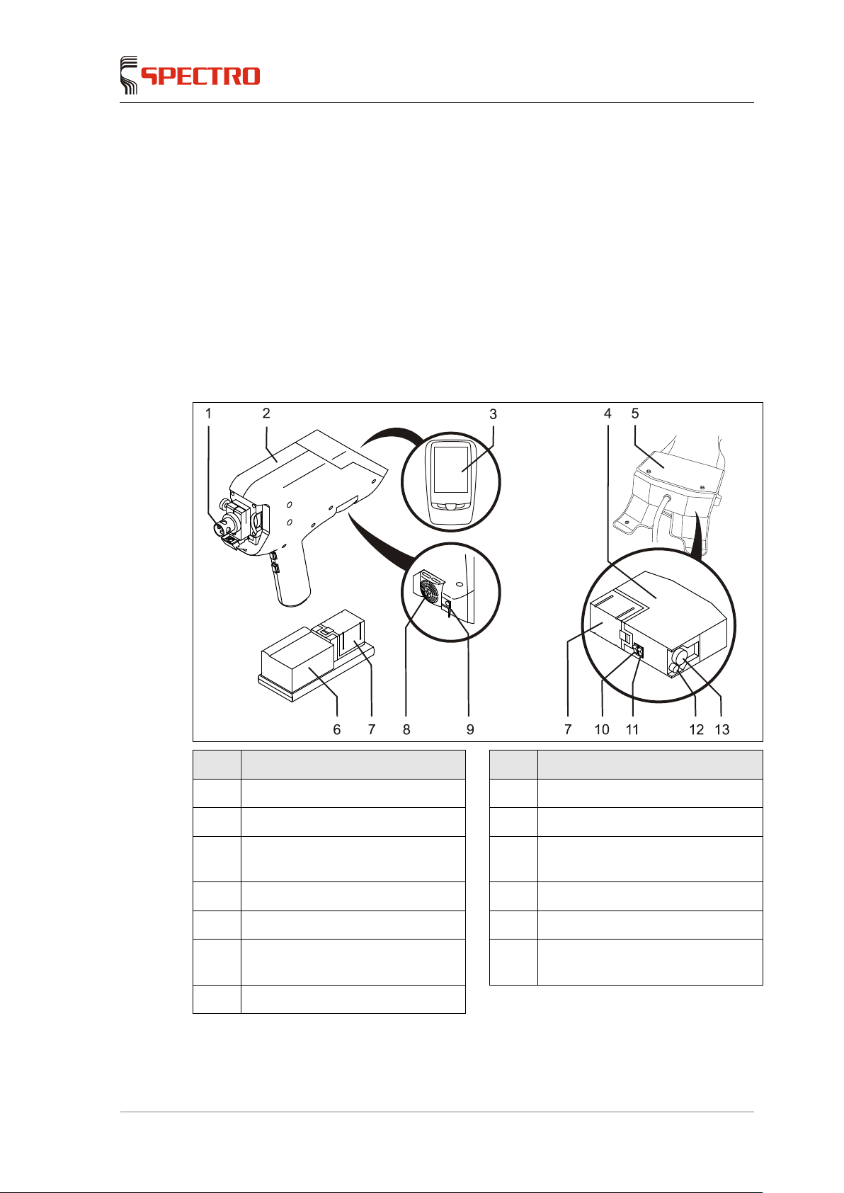
1.2 Overview
No. Component No. Component
1 Adapter, electrode 8 Air filter (probe)
2 Sample probe 9 USB port PDA
3
PDA (Personal Digital Assistant, a
small, flat computer)
10 On/off switch excitation “S”
(source/stand-by)
4 Housing (spectrometer) 11 On/off switch power supply “P”
5 Bag (spectrometer) 12 Fine dust filter unit
6 Charging station with integrated
charger and battery holder
13 CO2 filter unit
7 Battery pack
Page 6
Unit description
—
6 SPECTRO iSORT —
23.08.2013
1.3 Battery pack
A fully charged battery can handle up to approximately 300 to 400 measurements.
The exact number depends on the area of application (measurement parameters).
Note
Further information can be found in the supplied instruction manual of the battery
pack and the charging station.
1.3.1 Technical data
Designation Value
Capacity 24 V 3,3 Ah
1.3.2 Handling
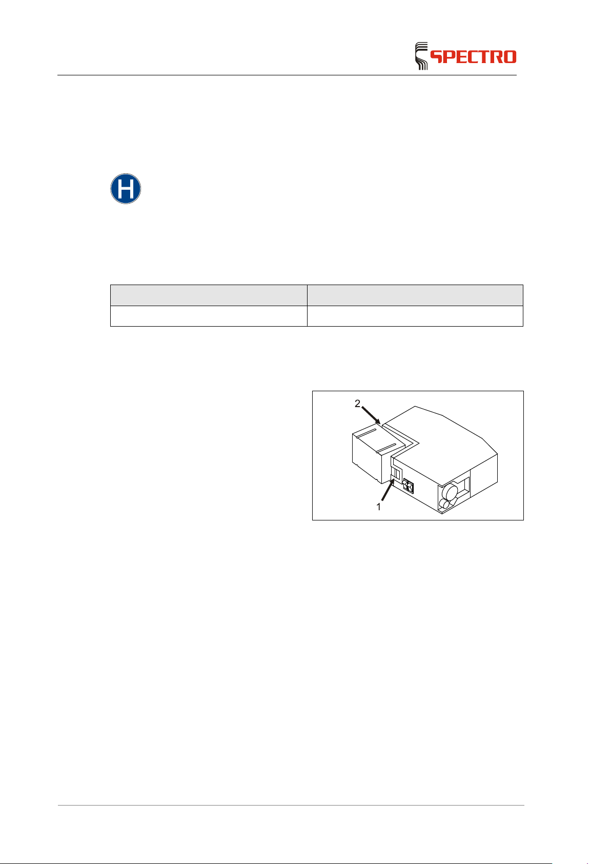
To change the battery pack, proceed as follows:
1. Unlock the battery pack and
remove it (1).
2. Put the charged battery pack
into the holder (2).
3. Push the battery pack in until it
locks into place (1).
Changing of the battery pack is now completed.
Page 7

Safety
SPECTRO iSORT
— 23.08.2013 —
7
2 Safety
Every user of the unit must have understood the present Operating Instructions.
This applies in particular to the safety regulations.
2.1 User information
Absolutely comply with all safety regulations. It serves your safety.
Observe all safety and accident prevention regulations at all times while
operating, maintaining and repairing the unit. This is e.g. DIN EN 61010 or a
comparable national standard.
Maintenance and repair may only be carried out by qualified personnel.
Check if the safety precautions work properly after every maintenance or
repair. This check is to be carried out according to VBG4 / DIN EN 61010 or a
comparable national standard.
Always have the unit maintained at the intervals specified by the manufacturer
and document the maintenance activities. This serves for maintaining the
operational safety of the unit.
Never tamper with the safety devices! If you feel that a safety device does not
work properly, shut down the unit immediately!
Absolutely observe the information labels provided on the unit.
Only genuine spare parts may be used for repairing the unit. The use of non-
genuine spare parts will result in loss of CE conformity.
The unit may be operated only in networks with a protective earth conductor.
Observe the associated safety regulations when using tools and operating
utilities.
Make sure that the unit is switched off prior to opening it.
2.2 Intended use
This unit analyzes and identifies metals. Only such metals may be analyzed for
which the unit has been calibrated by the manufacturer or by qualified technical
personnel.
Page 8

Safety
—
8 SPECTRO iSORT —
23.08.2013
2.3 Prohibited operating conditions
Operating the unit is prohibited if one of the following conditions applies:
If the unit is faulty or damaged.
If the unit is not subject to regular maintenance.
If the ambient conditions do not comply with the specification.
If the area where the unit is used is not a commercial/industrial premise.
2.4 Residual risk
This unit has been manufactured in accordance with the state of the art.
Nevertheless, a residual risk cannot be completely excluded.
Warning! Danger of injury
The analyses generate metal vapors. Depending on the sample material,
these vapors may be toxic, e.g. in case of heavy metals.
Ensure that protective equipment is worn in such cases, e.g. a breathing
apparatus and extraction equipment. The protective equipment must
ensure that the national threshold limit values in force and/or comparable
national standards will not be exceeded.
When the unit is switched on, there is a risk of suffering an electric shock
when the electrode is touched or when the sample is removed during a
measurement.
Such an electric shock is not dangerous to a healthy person. Low
currents and voltages below the threshold values specified in EN61010
are involved here. However, consequential accidents may occur, e.g.
falling down from a ladder.
The sample should not be touched while a measurement is in progress.
Avoid any contact with the electrode when the unit is on.
Always switch off the excitation (source) when working on the spark
stand (stationary spectrometers) or on the sample probe (mobile
spectrometers).
On mobile spectrometers, the probe can, if possible, be
disconnected from the unit.
The “P” switch (power) immediately switches the entire hardware off
with the exception of the PDA. Work on the probe can be performed
at once.
The “S” switch (source/stand-by) switches the excitation off. It takes
20-30 seconds until the excitation (source) is completely switched
off.
Voltage ranges, see page 9.
Page 9
Safety
SPECTRO iSORT
— 23.08.2013 —
9
There is a danger of burns when touching the electrode. Under normal
operating conditions, the temperature of the electrode may rise to several
hundred degrees.
Do not touch the electrode with bare hands even if the unit is switched
off. Always use tongs.
In order to avoid accidental sparking, the buttons “Reset” and “Start
Measurement” must be pressed continuously during the measurement. The
double-button operation is the default setting when the unit is supplied.
If the default setting is changed, it is possible to trigger the spark cycle by
pressing only the start button.
The electric arc in the spark stand or in the sample probe adapter generates
UV radiation.
Take suitable protective measures (e.g. wear safety glasses) whenever
the spark stand opening or the adapter opening is not completely
covered.
Note
The plasma is ignited with the help of a high
-voltage impulse.
Then a DC arc voltage (arc mode) is applied to the electrode.
The voltage ranges are shown in the following table.
High-voltage ignition impulse
Arc mode
Arc voltage
Arc mode
SPECTRO iSORT
TSC20
6-12 KV, typ. 8KV 30-60V, typ. 40V
Page 10
Technical data
—
10 SPECTRO iSORT —
23.08.2013
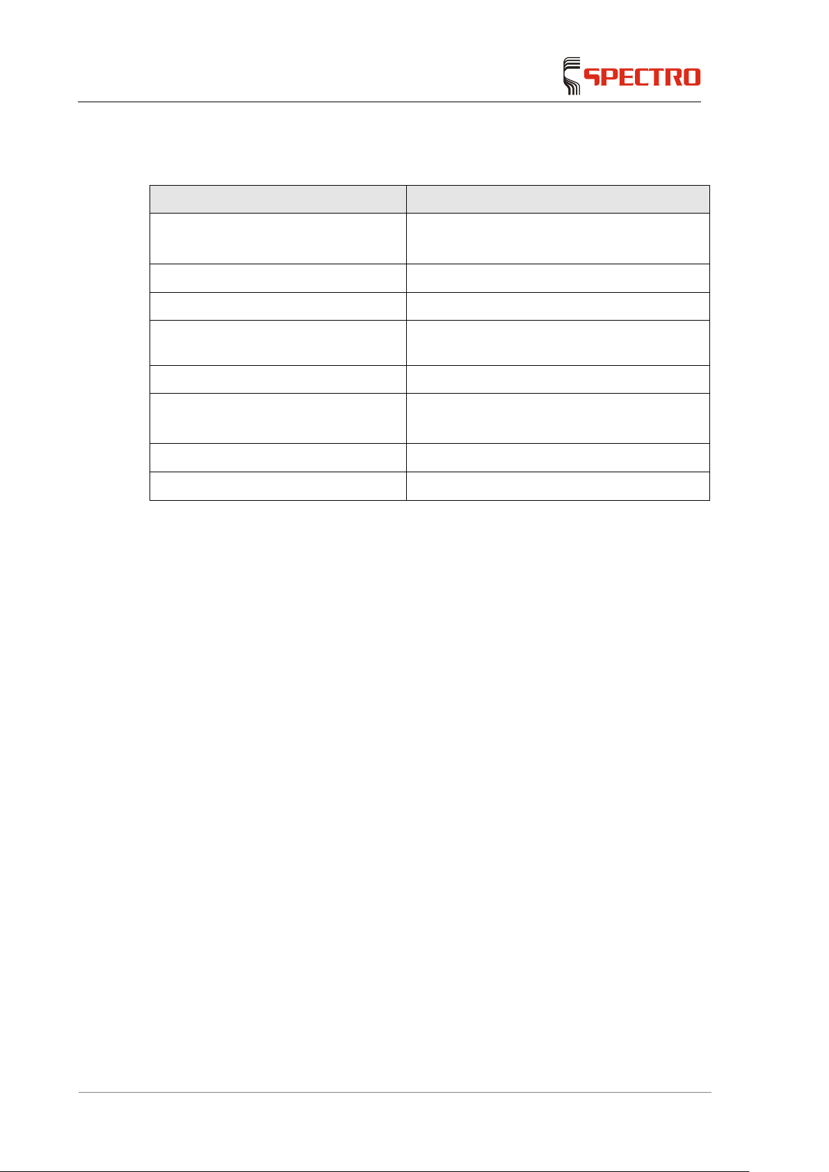
3 Tech n i ca l data
Designation Value
Power supply (charging station) 100 – 240 V +6 %/-10 % 50/60 Hz
(according to DIN EN 61010-1)
Power input during sample testing 300 W
Power input during stand-by 10 W
Power line fuse protection (charging
station)
16 A (slow-blow)
Storage conditions -20 – +50 °C; -5 – 120 °F
Temperature range 5 – 40 °C; 40 – 105 °F
(according to DIN EN 61010-1)
Air humidity 80% max. (according to DIN EN 61010-1)
Protection class IP 23 (DIN 40050)
Page 11
Transport/Use
SPECTRO iSORT
— 23.08.2013 —
11
4 Transport/Use
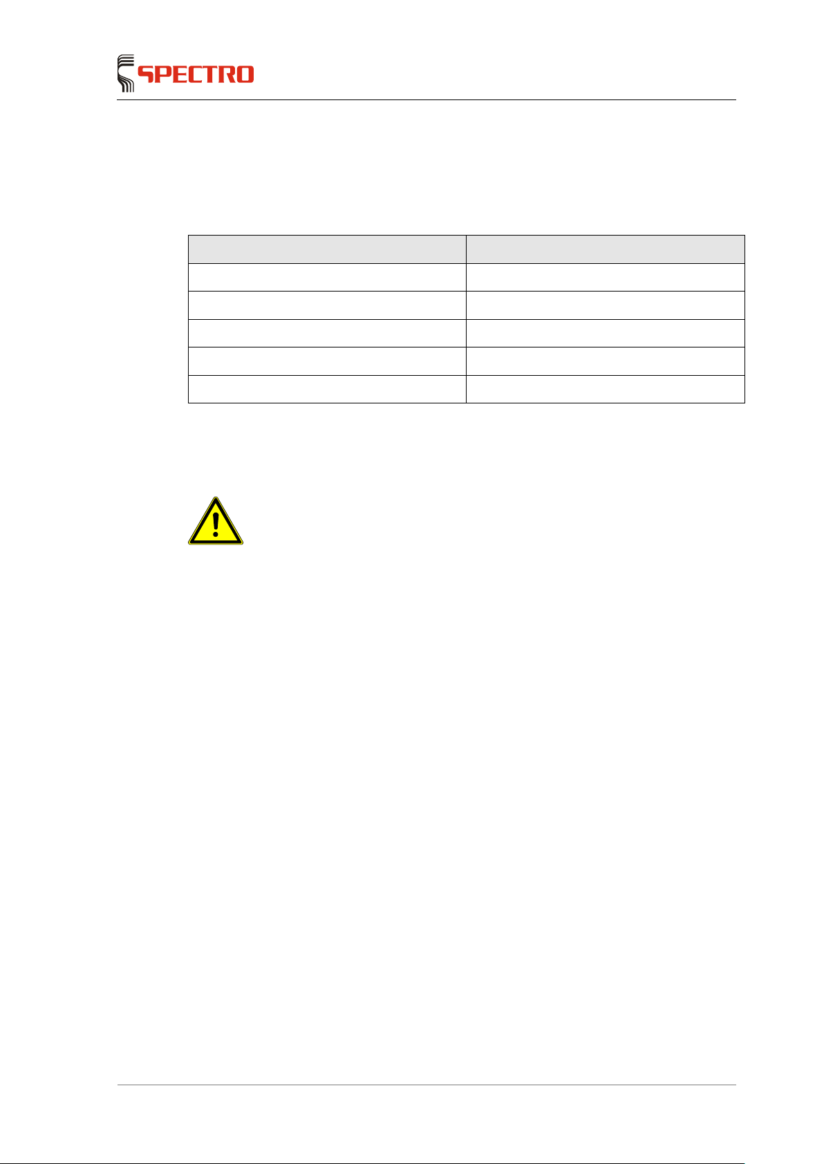
4.1 Dimensions and weight
Designation Value
Unit height (system case dimensions) 300 mm; 11.8“
Unit width (system case dimensions) 640 mm; 25.2“
Unit depth (system case dimensions) 360 mm; 14.2“
Unit weight (spectrometer + probe) 6 kg; 13.2 lbs
Unit weight (entire system in case) 18 kg; 39.7 lbs
4.2 Transport
Caution! Damage to unit!
If you carry the unit on your body, it may fall down and get damaged.
Make sure that the snap fasteners of the spectrometer bag are all closed.
Fasten the probe into the transport holder at the shoulder strap of the
spectrometer bag when you do not perform any measurements.
Switch off the excitation (source) when you do not perform any tests.
If you transport the unit in a passenger car,
transport the unit in the system case intended for this purpose.
Page 12
Transport/Use
—
12 SPECTRO iSORT —
23.08.2013
4.3 Use
Caution! Damage to unit!
Corrosive vapors may damage the unit.
Use the unit in an environment free from corrosive vapors.
Caution! Measurement errors!
Shocks to the unit during the measuring process may produce measurement
errors.
You should therefore avoid shocks during the measurements.
Measuring errors may result from temperature differences inside the unit.
Position yourself and the unit so that it cannot heat up on one side only.
Avoid mechanical bumps.
Page 13
Operation
SPECTRO iSORT
— 23.08.2013 —
13
5 Operation
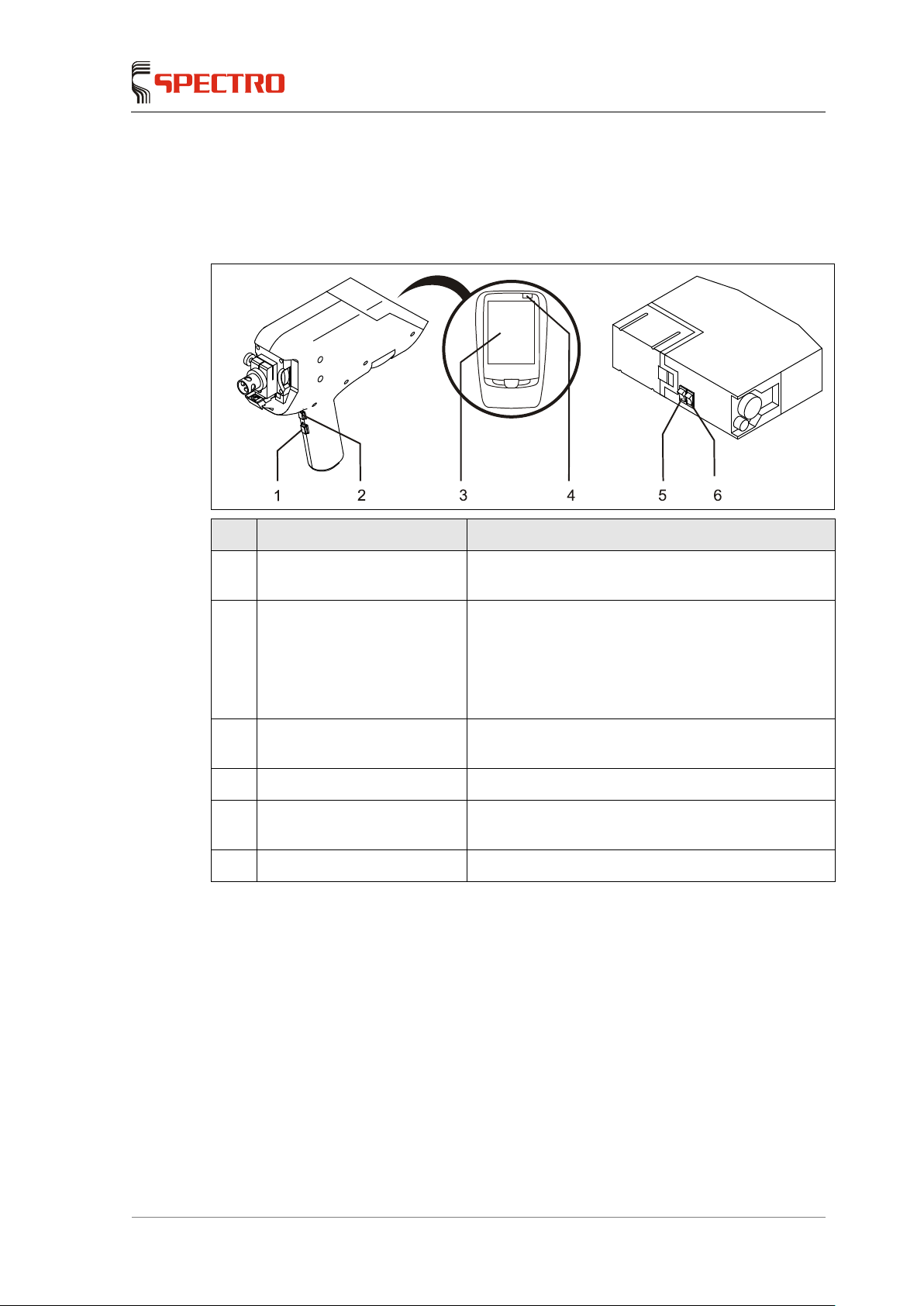
5.1 Overview of controls
No. Control Function
1 “Reset” button
Calculates mean values and resets error messages
of the PDA
2 “Start measurement” button Carries out the measurement
Must be pressed together with the “Reset”
button during the entire measurement.
The double-button operation is the default setting
when the unit is supplied
3 Touch-sensitive screen The unit software is controlled with the help of
buttons on the screen
4 PDA ON/OFF Switches the PDA on or off
5 Excitation “S”
(source/stand-by)
Sets the sample probe to stand-by mode
6 ON/OFF “P” (power) Switches the spectrometer on or off
Page 14
Operation
—
14 SPECTRO iSORT —
23.08.2013
5.2 Displays
5.2.1 Sample probe
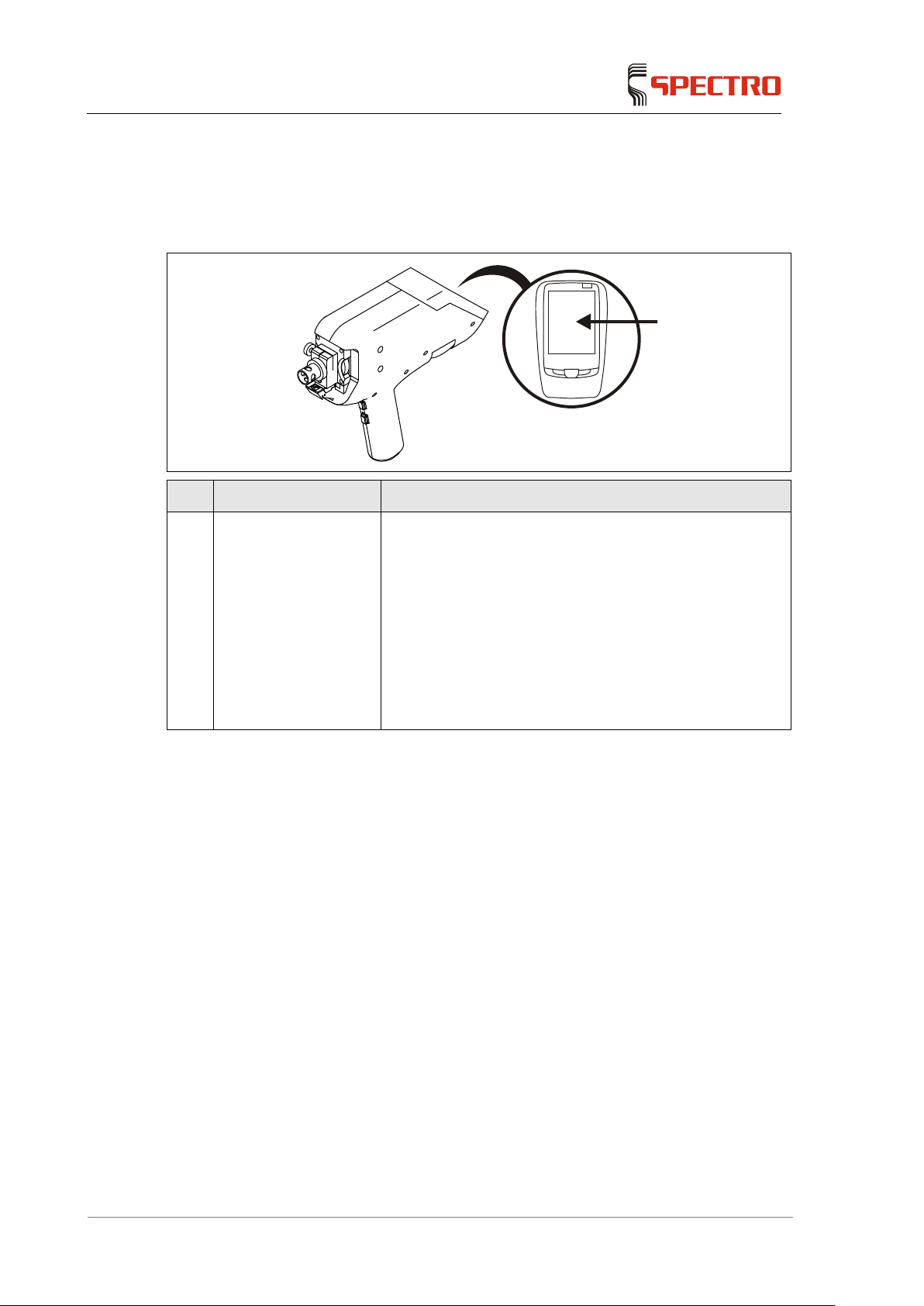
No. Display Function
1 Status display of
sample probe (PDA)
The screen displays the measuring window
The unit is ready for operation.
The screen shows a red surface
The unit is not ready for operation.
The software has switched to the safety mode
(no measurement has been performed for a long
time)
Fault
A measurement is carried out
Page 15
Operation
SPECTRO iSORT
— 23.08.2013 —
15
5.2.2 PDA screen
Caution! Damage to unit!
Do not touch
the screen with sharp or hard objects. The touch-sensitive surface
may be damaged.
Touch the screen with a plastic pen or with your finger.
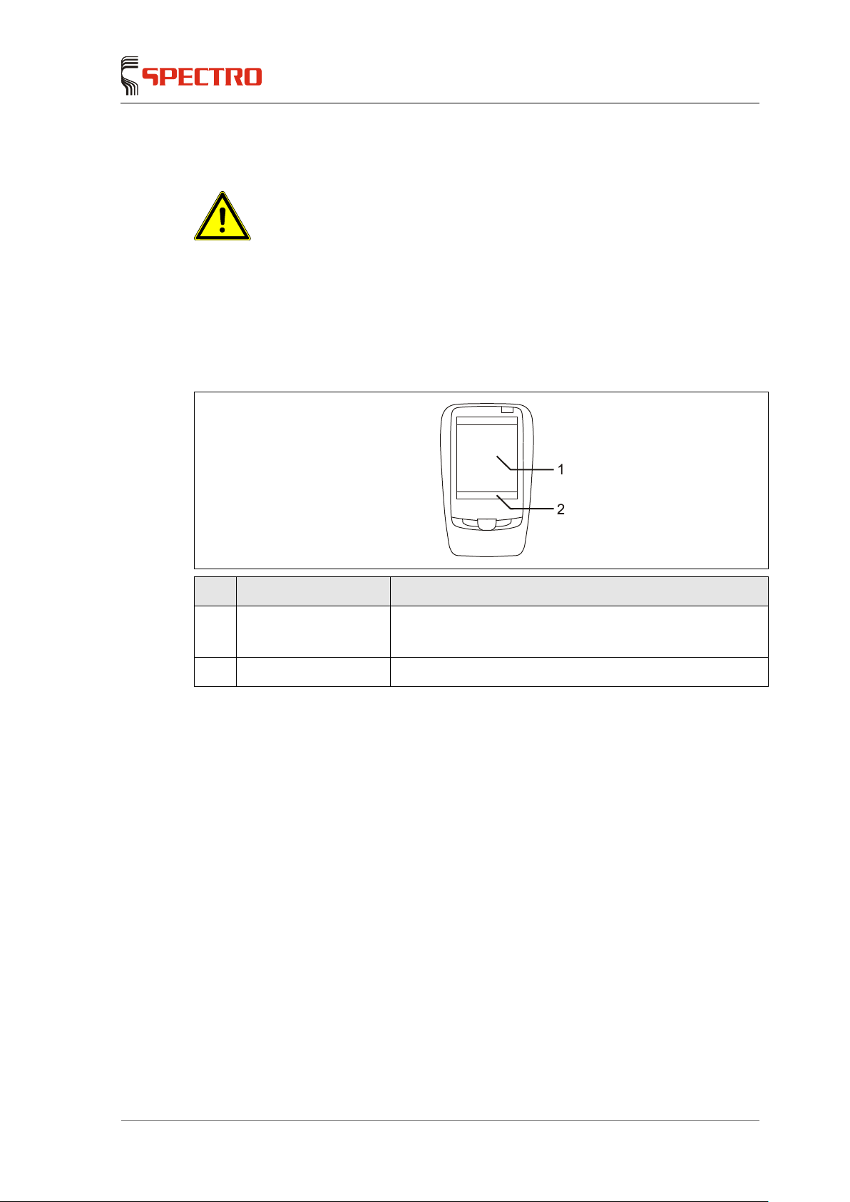
The surface of the screen reacts to touch (touch screen). Touch the buttons on the
screen to navigate in the control system.
No. Display Function
1 Program field Display of measurement results
The display field depends on the loaded program
2 Menu line Display of program menus
Page 16

Operation
—
16 SPECTRO iSORT —
23.08.2013
5.3 Preparing the unit for operation
Before switching on the unit, proceed as follows:
1. Ensure that
the battery pack is charged.
the battery pack is firmly locked in its holder.
the snap fasteners of the spectrometer bag are closed.
the filter cartridges (CO
2
and fine dust) are firmly screwed in.
2. Sling the unit from your shoulder.
The unit is now prepared.
5.4 Switching the unit on
To switch on the unit, proceed as follows:
1. Set the “P" switch (power) to position "1" (ON).
The unit is switched on.
2. Press the “ON/OFF” button of the PDA.
The program most recently used is started.
3. Set the “S” switch (source/stand-by) to position “1” (ON) (if the excitation has
not been switched on yet).
The PDA connected to the probe displays the measuring window.
The unit is now switched on.
Page 17

Operation
SPECTRO iSORT
— 23.08.2013 —
17
5.5 Switching the unit off
Warning! Danger of injury!
When t
he unit is switched on,
there is a danger of an electric shock when touching
the electrode or when removing the sample during a measurement.
Always switch off the unit when changing the electrodes and adapters.
The “P” switch (power) immediately switches the unit off with the exception of
the PDA. Work on the probe can be performed at once.
The “S” switch (source/stand-by) switches the excitation off. It takes 20-30
seconds until the excitation (source) is completely switched off.
To switch off the unit, proceed as follows:
1. Switch off the excitation (the LED of the “source” switch does not light).
2. To do so, set the “P" switch (power) to position "0" (OFF).
A message is displayed on the screen of the PDA.
The unit is now switched off.
3. Press the “ON/OFF” button of the PDA.
The PDA is switched off.
5.6 Carrying out the measurement
5.6.1 Preparing the measurement
Before starting the measurement, proceed as follows:
1. Check the adapter and the sample for any moisture.
No moisture may be visible on the outside.
Dry the sample if required.
2. Check if the adapter is clean.
3. Ensure that the right electrode and adapter are installed.
4. Check the safety measures if you work with toxic samples.
5. Select the task in the “Tasks” menu.
The measurement is now prepared.
Page 18

Operation
—
18 SPECTRO iSORT —
23.08.2013
5.6.2 Measuring
Warning! Danger of injury!
When the unit switched on, there is a danger of an electric shock on the electrode
or on the sample. This may happen if during a measurement the contact to the
sample probe adapter is
interrupted.
Such an electric shock is not dangerous to a healthy person. Low currents and
voltages below the threshold values specified in EN61010 are involved here.
However, consequential accidents may occur, e.g. falling down from a ladder.
Make sure t
hat the sample never loses contact with the sample probe adapter
during an analysis.
Example of measurement: Approximate analysis
Proceed as follows to carry out a scan:
1. Open the "Tasks" menu to call up a program for approximate analyses.
2. Hold the sample probe (adapter) on the sample.
3. Press the "Start measurement" button and the “Reset” button during the entire
measurement.
The measurement is carried out automatically.
Make sure that the position of the probe and of the sample with regard to
each other does not change. A change in the sparking position may lead
to incorrect measurement results.
The measurement is terminated automatically.
The sample probe status display lights up red during the measurement
(PDA screen).
The sample probe status display switches over to the measuring window
when the measurement is complete.
If necessary, the unit will ask you to carry out an ICAL standardization,
see page 20.
The results are displayed on the screen.
The measurement is now complete.
Page 19

Operation
SPECTRO iSORT
— 23.08.2013 —
19
Example measurement approximate analysis with “fingerprint”
Note
During measurements in the fingerprint mode, the arc is briefly switched off and on
again for the duration of the arithmetic fingerprint operations. This functions saves
the energy of the storage battery.
Proceed as follows to carry out a measurement:
1. Open the "Tasks" menu to call up a program with fingerprint mode.
2. Hold the sample probe (adapter) on the sample.
3. Press the "Start measurement" button and the “Reset” button during the entire
measurement.
The measurement is carried out automatically.
Make sure that the position of the probe and of the sample with regard to
each other does not change. A change in the sparking position may lead
to incorrect measurement results.
The measurement is terminated automatically.
The sample probe status display lights up red during the measurement
(PDA screen).
The sample probe status display switches over to the measuring window
when the measurement is complete.
If necessary, the unit will ask you to carry out an ICAL standardization,
see page 20.
The results are displayed on the screen.
The measurement is now complete.
Example of measurement: Sorting
Proceed as follows to carry out a scan:
1. Open the "Tasks" menu to call up a program for sorting.
2. First measure a reference sample three times in succession.
Hold the sample probe (adapter) on the sample.
Press the "Start measurement" button and the “Reset” button during the
entire measurement.
The measurement is carried out automatically.
The measurement is terminated automatically.
The sample probe status display lights up red during the
measurement (PDA screen).
The sample probe status display switches over to the measuring
window when the measurement is complete.
Page 20

Operation
—
20 SPECTRO iSORT —
23.08.2013
The sample probe status display switches over to the measuring
window when the second measurement is complete and the result is
good. If the result is bad, an error message is displayed in red. The
measurement must be repeated. The third measurement is carried
out in the same way.
If the result is good, the "Pass" counter on the screen adds one point to
its count (depending on program settings).
3. Now measure the desired sample.
If the result is good, the "Pass" counter on the screen adds one point to
its count. The next sample can be measured.
If the result is bad, the "Fail" counter on the screen adds one point to its
count.
Depending on the program settings, two repeated measurements
must be carried out. If these are bad as well, the "bad samples"
counter on the screen adds one point to its count.
The next sample can be measured.
The measurement is now complete.
Standardization of measuring unit (ICALization)
Note
For ICAlisation, the
star electrode adapter must always be used. However, a stick
electrode must be used as the electrode
A reference sample is measured five times to perform standardization. The
average values of these measurement results are calculated and stored in the
unit.
Proceed as follows to standardize the unit:
1. Place a clean rod electrode (silver electrode) in the sample probe.
2. Start the ICAL function via the “ICAL” menu.
3. Follow the instructions on the screen and perform the necessary five
measurements with the reference sample.
4. Incorrect measurements are highlighted by colors in the ICAL measurement
window and can be deleted. Please repeat the corresponding measurements.
The unit is now standardized.
Page 21
Operation
SPECTRO iSORT
— 23.08.2013 —
21
5.7 Replacing parts of sample probe
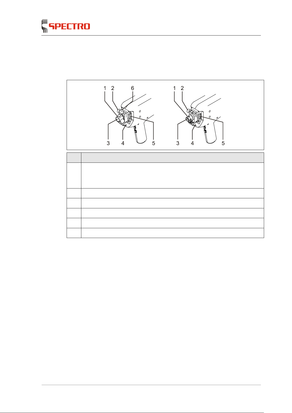
5.7.1 Sample probe parts overview
No. Display
1 Adapter
for star electrode (left)
for rod electrode (right)
2 Knurled screw for the adapter
3 Electrode
4 Housing with windows for the optical fiber
5 Electrode locking wheel
6 Knurled screw for turning the star electrode
Page 22

Operation
—
22 SPECTRO iSORT —
23.08.2013
5.7.2 Changing the adapter
Warning! Danger of injury!
When t
he unit is switched on, there is a danger of
an electric shock when touching
the electrode or when removing the sample during a measurement.
Always switch off the unit when changing the electrodes and adapters.
The “P” switch (power) immediately switches the unit off with the exception of
the PDA. Work on the probe can be performed at once.
The “S” switch (source/stand-by) switches the excitation off. It takes 20-30
seconds until the excitation (source) is completely switched off.
If you want to use another electrode type, you have to change the adapter.
To change the adapter, proceed as follows:
1. Switch off the unit.
2. Loosen the knurled screw of the adapter.
3. Pull out the adapter.
4. Plug in the new adapter.
The adapter for the star electrode has a locking mechanism.
Press the adapter beyond the resistance.
The adapter must make contact on its entire surface.
On the adapter for the rod electrode, one of the openings must point
towards the optical fiber.
5. Fix the adapter in place using the knurled screw.
6. Switch the unit on again, see page 16.
The adapter has now been changed.
Page 23
Operation
SPECTRO iSORT
— 23.08.2013 —
23
5.7.3 Changing the electrode
Warning! Danger of injury!
When t
he unit is switched on, there is a danger of an electric shock when
touching
the electrode or when removing the sample during a measurement.
Always switch off the unit when changing the electrodes and adapters.
The “P” switch (power) immediately switches the unit off with the exception of
the PDA. Work on the probe can be performed at once.
The “S” switch (source/stand-by) switches the excitation off. It takes 20-30
seconds until the excitation (source) is completely switched off.
When using arc discharge, silver of copper electrodes are used.
To change the electrode, proceed as follows:
1. Switch off the unit.
The LED of the “source” switch does not light.
2. Loosen the electrode on the locking wheel.
The electrode is spring-loaded. For this reason, hold the electrode tight.
3. Pull out the electrode.
4. Insert the new electrode.
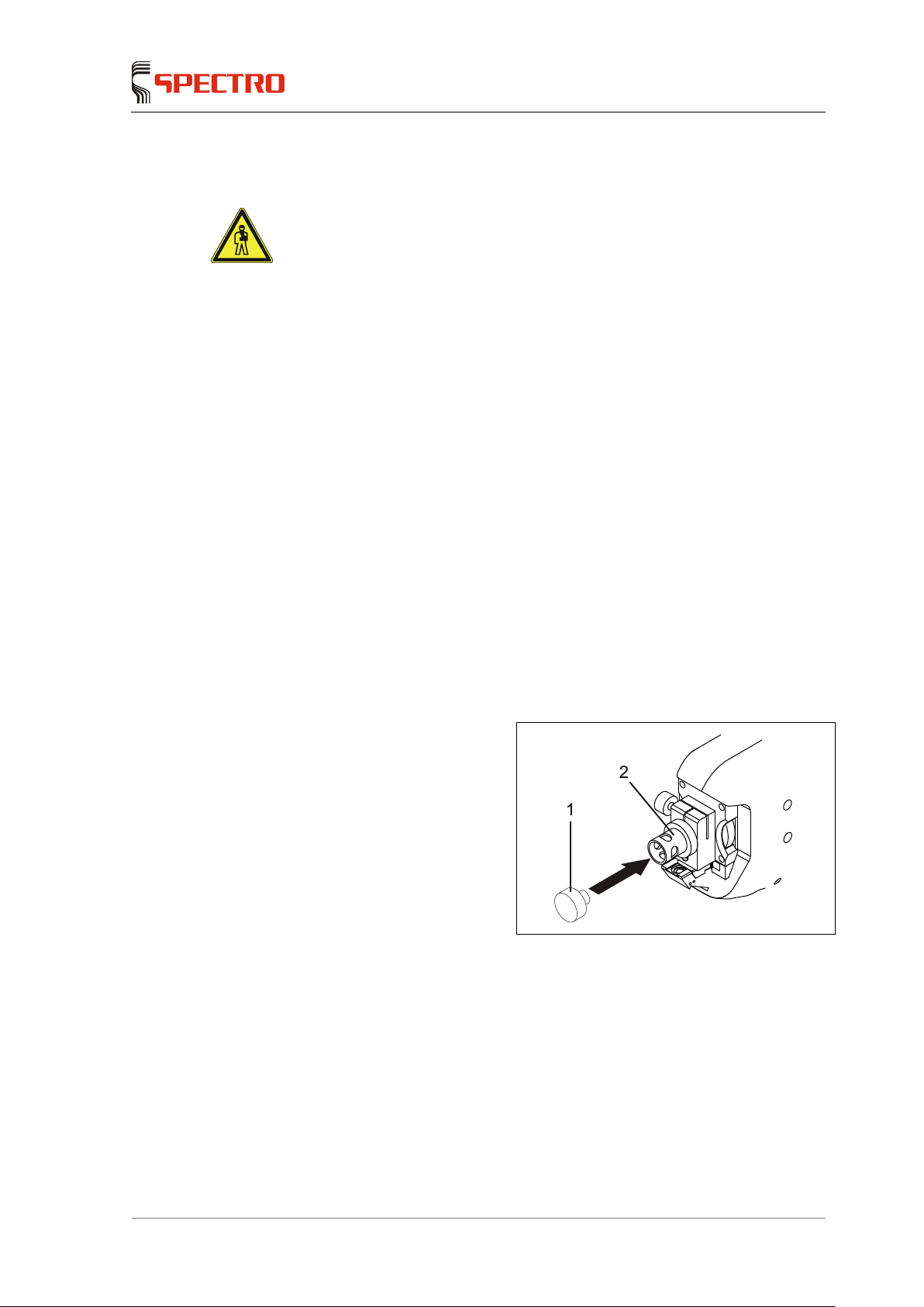
5. Set the electrode gap using the
spacer.
Press the spacer (1) on the
adapter (2). The electrode
is pushed to its correct
position.
6. Fix the electrode in place using the locking wheel.
7. Switch the unit on again, see page 16.
The electrode change is now complete.
Page 24
Maintenance
—
24 SPECTRO iSORT —
23.08.2013
6 Maintenance
6.1 Maintenance schedule
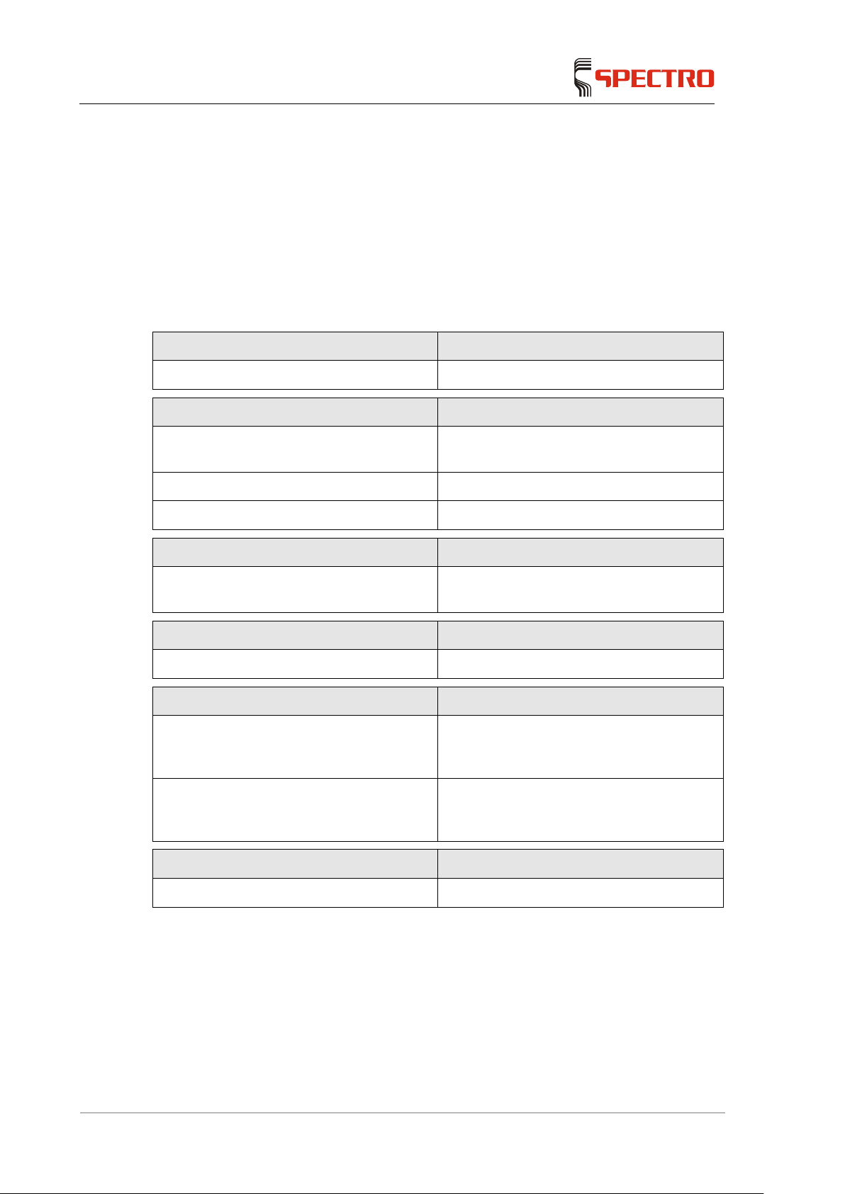
The maintenance intervals specified in the following table are guidelines which
should be observed as a minimum requirement. The maintenance intervals may
vary, depending on the use of the unit.
To ensure flawless function of the unit, carry out the following maintenance work:
After each measurement Maintenance work to be carried out
Clean electrode Clean the electrode with a small wire brush.
Start of work Maintenance work to be carried out
1. Check of cleaning system Check whether the filter cartridges are
properly installed
2. Cleaning the adapter See page 25.
3. ICALization See page 20.
If necessary
Clean the windows of the sample probe and
of the adapter
See page 25.
Every month
Clean the air filter (probe) Every month or more often if necessary
Every six months
Cleaning system: Fine dust filter Replace every six months or more
frequently if necessary (the system will
display a message)
Cleaning system: CO2 filter cartridge Replace every six months or more
frequently if necessary (the system will
display a message)
Further maintenance work
Replace the ICALization sample
Page 25
Maintenance
SPECTRO iSORT
— 23.08.2013 —
25
6.2 Cleaning the adapter
During the measurements, the adapter gets soiled.
After completing work, clean the adapter on the inside and outside, using a cloth
free of lint, oil and grease. Commercially available cotton swabs are also useful for
cleaning.
6.3 Cleaning the light inlet windows of the sample probe and of the adapter
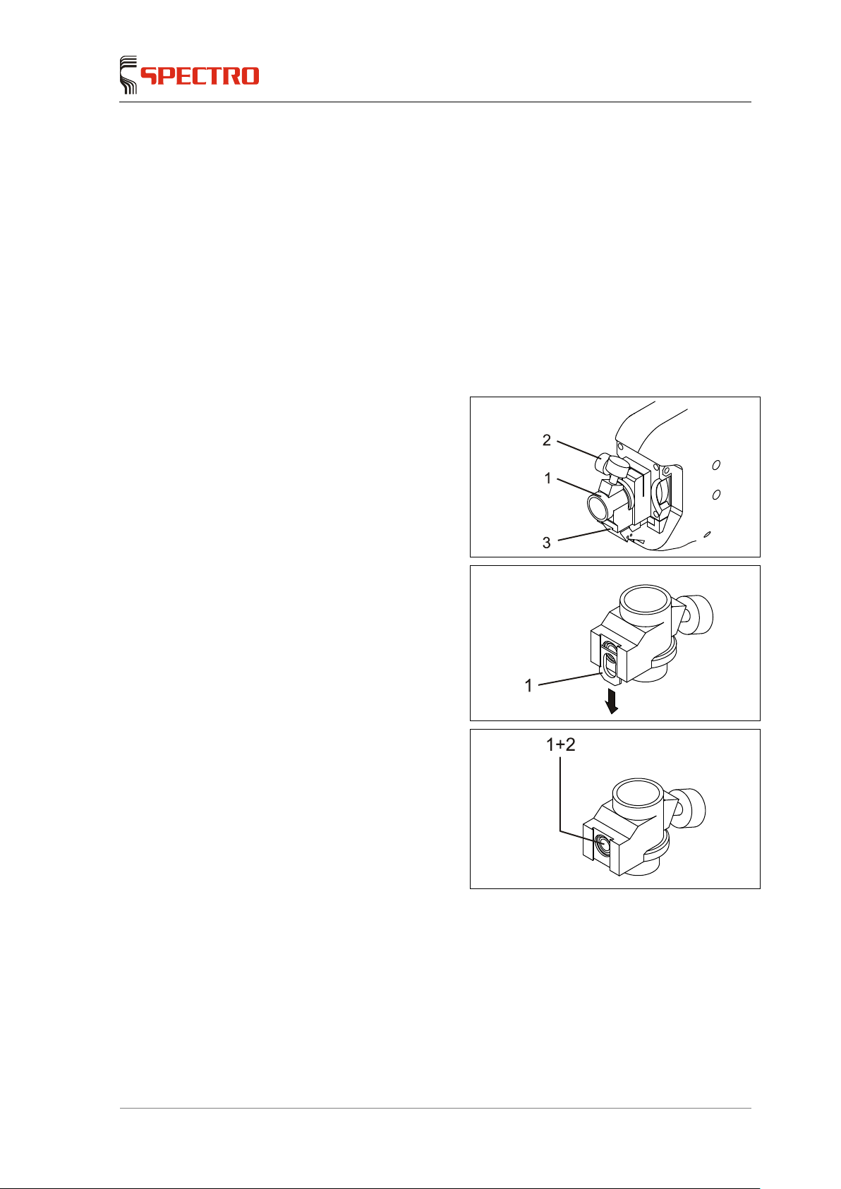
To clean the light inlet windows proceed as follows:
1. Loosen the adapter (1) using the
knurled screw (2) and pull it off.
Clean the light inlet window
(3) of the sample probe with
a cotton swab.
2. Take the adapter and push the
window holder (1) carefully out
of the guide.
3. Remove the light inlet window(s)
(1) and the exposed O-ring (2).
Make sure not to touch the
optical surfaces.
4. Clean light inlet window using
optical paper or a lint-free soft
cloth.
5. Refit the light inlet window.
Make sure that the O-ring fits in properly under the light inlet window.
6. Re-attach the adapter to the sample probe.
The cleaning of the light inlet windows of the sample probe and of the adapter
is now completed.
Page 26

Maintenance
—
26 SPECTRO iSORT —
23.08.2013
6.4 Changing/cleaning the air filter (probe)
Change the air filter every month (or more often if necessary).
To replace the air filter, proceed as follows:
1. Remove the air filter cover.
2. Replace the air filter or clean it.
3. Re-fit the air filter cover.
The air filter has now been replaced.
6.5 Cleaning/sharpening the electrodes
Clean the electrodes after work is complete.
The "soft" rod electrodes (silver and copper) must be newly sharpened when their
tip is worn.
Page 27
Troubleshooting
SPECTRO iSORT
— 23.08.2013 —
27
7 Troubleshooting
Caution! Damage to unit!
The unit may be damaged if repairs are not carried out
properly. Do not attempt to
repair the unit yourself. Always inform your supervisor.
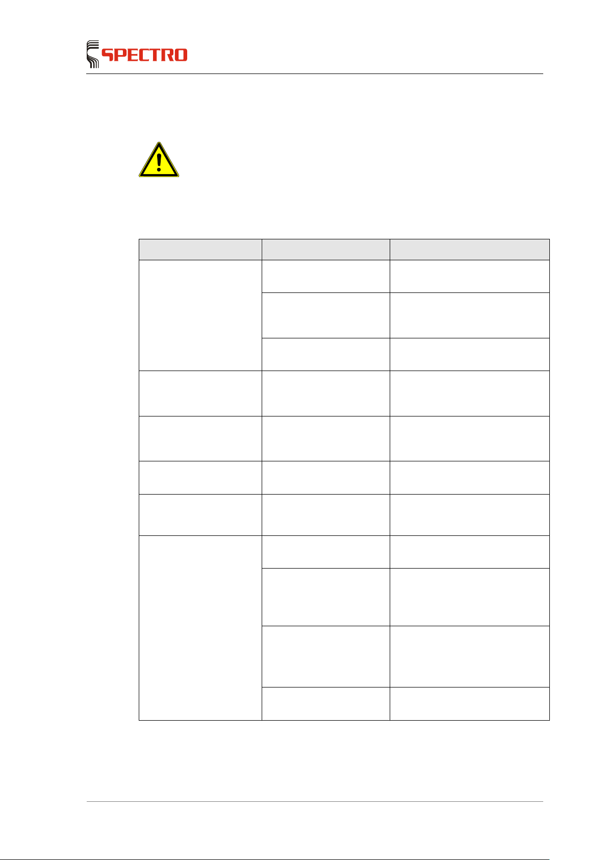
Fault Possible cause Remedy
The unit cannot be
switched on
The battery pack is not
firmly locked in the holder.
Let the battery pack firmly lock in
place.
The battery pack is not
charged.
Charge the battery pack
according to separate
instructions.
One of the spectrometer
components is defective.
Please contact your service
center
The unit can be switched
on, but no data are
shown on the screen.
The battery of the PDA is
defective.
Please contact your service
center
The unit can be switched
on, but no data are
shown on the screen.
The PDA is not switched
on.
Switch on the PDA.
The screen does not
react to any entries.
The screen is defective. Please contact your service
center
The screen does not
react to any entries.
The screen is not properly
adjusted.
Recalibrate the screen with the
help of the software.
The unit does not
produce any sparks
The electrode gap is too
small.
Clean the electrode and re-
adjust
the gap using the spacer.
The “Start Measurement”
button or the “Reset”
button of the probe is
defective.
Please contact your service
center
The source parameters of
the program used were
modified or deleted.
Have former
settings restored
by qualified personnel.
Please contact your service
center
The source is defective Please contact your service
center
Page 28

Spare parts and consumables
—
28 SPECTRO iSORT —
23.08.2013
Fault Possible cause Remedy
The result falls below the
stored reference element
limit values (error
message).
The adapter in the "Arc"
mode is reversed.
Turn the adapter so that one
opening faces the optical fiber
window.
The adapter is not locked
in properly up to the stop.
Check adapter seat and correct it
if necessary.
The electrode gap is not
correct.
Adjust the electrode gap using
the spacer.
8 Spare parts and consumables
You can find the spare parts and consumables for this unit under "Support - Parts
Catalog" on our website at www.spectro.com.
 Loading...