

Page 1
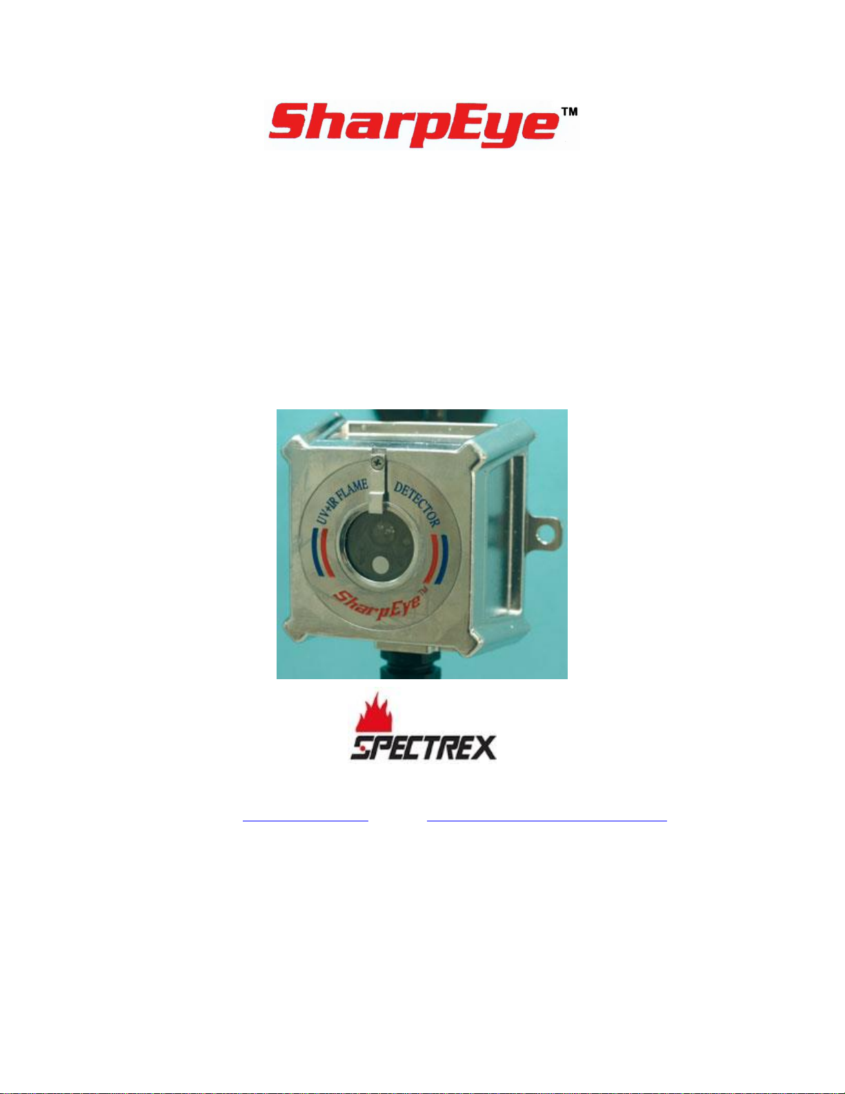
Model 20/20ML
UV/IR Mini Flame Detector
User Guide
8200 Market Blvd, Chanhassen, MN 55317, USA
Phone: +1 (973) 239 8398 Fax: +1 (973) 239 7614
Website: www.spectrex.net Email: [email protected]
Page 2

Page 3

Legal Notice
The SPECTREX SharpEye Optical Flame Detector described in this document is the property of Rosemount.
No part of the hardware, software or documentation may be reproduced, transmitted, transcribed, stored in a
retrieval system or translated into any language or computer language, in any form or by any means, without prior
written permission of Rosemount.
While great efforts have been made to assure the accuracy and clarity of this document, Rosemount assumes no
liability resulting from any omissions in this document, or from misuse of the information obtained herein. The
information in this document has been carefully checked and is believed to be entirely reliable with all of the
necessary information included. Rosemount reserves the right to make changes to any products described herein
to improve reliability, function, or design, and reserves the right to revise this document and make changes from
time to time in content hereof with no obligation to notify any persons of revisions or changes. Rosemount does not
assume any liability arising out of the application or any use of any product or circuit described herein; neither
does it convey license under its patent rights or the rights of others.
Warranty
SPECTREX agrees to extend to Purchaser/Distributor a warranty on the SPECTREX supplied components of the
SharpEye products. SPECTREX warrants to Purchaser/Distributor that the products are free from defects in
materials and workmanship for a period of three (3) years, commencing with the date of delivery to
Purchaser/Distributor. SPECTREX expressly excludes damage incurred in transit from the factory or other damage
due to abuse, misuse, improper installation, or lack of maintenance or “Act of God” which are above and beyond its
control. SPECTREX will, upon receipt of any defective product, transportation prepaid, replace it at its sole
discretion if found to have been defective when shipped. Said replacement is SPECTREX’S sole liability under this
warranty and SPECTREX’S liability shall be limited to replacement of the component found defective and shall not
include any liability for consequential or other damages. The customer is responsible for all freight charges and
taxes due on shipments both ways. This warranty is exclusive of all other warranties express or implied.
TM767100 Rev. (Ad), May 2019
Page 4

Page 5

TM767100 Rev. (Ad), May 2019 v
Table of Contents
Table of Contents ............................................................................................ v
List of Figures ................................................................................................ ix
List of Tables .................................................................................................. ix
1 About this Guide ...................................................................................... 11
1.1 Release History ..................................................................................... 11
1.2 Glossary and Abbreviations .................................................................... 12
1.3 Notifications ......................................................................................... 13
2 Product Overview .................................................................................... 15
2.1 Technical Description ............................................................................. 15
2.2 Principles of Operation ........................................................................... 15
2.3 Sensing Elements ................................................................................. 16
2.4 Modbus RS-485 .................................................................................... 16
2.5 Types and Models ................................................................................. 16
3 Performance ............................................................................................ 19
3.1 Detection Sensitivity ............................................................................. 19
3.1.1 Standard Fire ................................................................................. 19
3.1.2 Sensitivity Ranges: ......................................................................... 19
3.1.3 Other Fuels .................................................................................... 20
3.2 Cone of Vision ...................................................................................... 21
3.3 False Alarms Prevention ......................................................................... 21
4 Operation ................................................................................................ 23
4.1 Visual Indications .................................................................................. 23
4.2 Output Signals ...................................................................................... 23
4.2.1 Optional Latching ............................................................................ 24
4.2.2 Built-In-Test ................................................................................... 25
4.3 Detector Mode Setup ............................................................................. 25
4.3.1 Detector Settings ............................................................................ 25
4.3.2 Detector’s Various Functions ............................................................ 25
4.3.3 Detector Default Setup .................................................................... 26
4.4 Built-In-Test ......................................................................................... 27
4.4.1 General ......................................................................................... 27
4.4.2 Principles ....................................................................................... 27
4.4.3 Automatic and Manual BIT ............................................................... 27
Page 6

vi SharpEye™ UV/IR Mini Flame Detector User Guide
4.4.4 Manual BIT Only ............................................................................. 28
5 Technical Specifications ........................................................................... 29
5.1 Electrical Specifications .......................................................................... 29
5.1.1 Operating Voltage ........................................................................... 29
5.1.2 Power Consumption ........................................................................ 29
5.1.3 Electric Input Protection ................................................................... 29
5.1.4 Electrical Outputs ............................................................................ 29
5.2 Communications Network....................................................................... 30
5.3 Mechanical Specifications ....................................................................... 30
5.3.1 Enclosure Options ........................................................................... 30
5.3.2 Water and Dust-Tight ...................................................................... 30
5.3.3 Electronic Modules .......................................................................... 30
5.3.4 Electrical Connection ....................................................................... 30
5.3.5 Dimensions .................................................................................... 30
5.3.6 Weight .......................................................................................... 30
5.4 Environmental Specifications .................................................................. 30
5.4.1 High Temperature ........................................................................... 30
5.4.2 Low Temperature ............................................................................ 31
5.4.3 Humidity ........................................................................................ 31
5.4.4 Salt Fog ......................................................................................... 31
5.4.5 Dust .............................................................................................. 31
5.4.6 Vibration ........................................................................................ 31
5.4.7 Mechanical Shock............................................................................ 31
5.4.8 Electromagnetic Compatibility (EMC) ................................................. 31
6 Installation Instructions .......................................................................... 33
6.1 Scope .................................................................................................. 33
6.2 General Considerations .......................................................................... 33
6.3 Preparation for Installation ..................................................................... 34
6.4 Installation ........................................................................................... 34
6.4.1 Tilt Mount Kit ................................................................................. 34
6.4.2 Tilt Installation ............................................................................... 35
6.5 Detector Mounting ................................................................................ 38
6.6 Wiring Function..................................................................................... 38
6.6.1 Power Supply ................................................................................. 38
6.6.2 Manual Bit Activation ....................................................................... 38
6.6.3 Fault Relay ..................................................................................... 38
Page 7

TM767100 Rev. (Ad), May 2019 vii
6.6.4 Alarm Relay ................................................................................... 38
6.6.5 4–20mA Output .............................................................................. 39
6.6.6 RS-485 .......................................................................................... 39
6.6.7 Ground .......................................................................................... 39
6.7 Operation Mode .................................................................................... 39
6.7.1 Programmable Function ................................................................... 39
6.7.2 Address ......................................................................................... 39
6.7.3 Alarm Delay ................................................................................... 39
7 Operating Instructions ............................................................................ 41
7.1 Scope .................................................................................................. 41
7.2 Power-Up ............................................................................................. 41
7.3 Reset................................................................................................... 42
7.4 Functional Testing ................................................................................. 42
7.4.1 Manual BIT Test .............................................................................. 42
7.4.2 Testing with Flame Simulator Model FS1200 ....................................... 42
7.5 Safety Precautions ................................................................................ 43
8 Maintenance Instructions ........................................................................ 45
8.1 Scope .................................................................................................. 45
8.2 Maintenance Instrumentation and Personnel ............................................ 45
8.3 Preventive Maintenance Procedures ......................................................... 45
8.4 Periodic Maintenance Procedures ............................................................ 45
8.4.1 Power-Up Procedure ........................................................................ 45
8.4.2 Functional Test Procedure ................................................................ 45
8.5 Maintenance Records ............................................................................. 46
8.6 Troubleshooting .................................................................................... 46
8.6.1 Fault Indication .............................................................................. 46
8.6.2 False Alarm or Warning Indication ..................................................... 46
Appendix A: Typical Wiring Configurations ............................................... 47
A.1 RS-485 Communications Network ........................................................... 48
Appendix B: Flame Simulator FS-1200 ...................................................... 53
Appendix C: Ordering Information ........................................................... 55
C.1 Unpacking ............................................................................................ 55
C.2 Operating Instructions ........................................................................... 55
C.2.1 Range ........................................................................................... 56
C.2.2 Charging the Battery ....................................................................... 56
C.2.3 Replacing the Battery ...................................................................... 58
Page 8

viii SharpEye™ UV/IR Mini Flame Detector User Guide
C.3 Technical Specifications ......................................................................... 58
C.3.1 General ......................................................................................... 58
C.3.2 Electrical ........................................................................................ 58
C.3.3 Physical ......................................................................................... 58
C.3.4 EMI Compatibility ............................................................................ 59
Technical Support ......................................................................................... 64
Page 9

TM767100 Rev. (Ad), May 2019 ix
List of Figures
Figure 1: Model Definitions ................................................................................. 17
Figure 2: UV/IR Flame Detector .......................................................................... 17
Figure 3: Flame Detector Assembly: Outline Drawing of Cable Output Option ........... 18
Figure 4: Horizontal and Vertical Fields of View ..................................................... 21
Figure 5: 20/20ML LED ...................................................................................... 23
Figure 6: Detector and Tilt Mount Assembly .......................................................... 36
Figure 7: Tilt Mount Assembly - Outline Drawing ................................................... 37
Figure 8: Connector Interface Option ................................................................... 47
Figure 9: Cable Interface Option ......................................................................... 48
Figure 10: RS-485 Networking ............................................................................ 49
Figure 11: 4–20mA Wiring (Sink Option) .............................................................. 49
Figure 12: 4–20mA Wiring (Source Option) .......................................................... 50
Figure 13: Typical Wiring for 4 Wire Controllers .................................................... 50
Figure 14: SharpEye Flame Simulator FS-1200 ..................................................... 53
Figure 15: Flame Simulator Battery Replacement .................................................. 57
List of Tables
Table 1: Response Sensitivity Ranges for Other Fuels ............................................ 20
Table 2: 20/20ML - Immunity to False Alarm Faults ............................................... 22
Table 3: Detector States .................................................................................... 24
Table 4: Output Signals Versus Detector State ...................................................... 24
Table 5: Time Delay .......................................................................................... 26
Table 6: Function Setup ..................................................................................... 26
Table 7: Default Function Setup .......................................................................... 27
Table 8: Contact Ratings .................................................................................... 29
Table 9: Tilt Kit ................................................................................................. 34
Table 10: Sensitivity Ranges ............................................................................... 56
Table 11: Immunity Tests .................................................................................. 59
Table 12: Emission Tests .................................................................................... 59
Page 10

Page 11
About this Guide
TM767100 Rev. (Ad), May 2019 11
1 About this Guide
This guide describes the SharpEye Model 40/40L, LB, L4, L4B (UV/IR) Flame
Detector and its features and provides instructions on how to install, operate, and
maintain the detector.
Note:
This user guide should be read carefully by all individuals who have or
will have responsibility for using, maintaining, or servicing the
product.
This guide includes the following chapters and appendices:
• Chapter 1, About this Guide, details the layout of the guide, includes the
release history, a glossary and abbreviations, and explains how notifications
are used in the guide.
• Chapter 2, Product Overview, describes the detector’s theory of operation.
• Chapter 3, Performance, describes the detector’s features and capabilities.
• Chapter 4, Operation, describes the detector’s operation modes, user
interface and indications.
• Chapter 5, Technical Specifications, describes the detector’s electrical,
mechanical, and environmental specifications.
• Chapter 6, Installation Instructions, describes installation as well as
wiring and mode setting.
• Chapter 7, Operating Instructions, describes operation and power-up
procedures.
• Chapter 8, Maintenance Instructions, describes maintenance and support
procedures.
• Appendix A, Typical Wiring Configurations, describes wiring diagrams for
installation.
• Appendix B, Flame Simulator FS-1200, describes the Flame Simulator and
its operation.
• Appendix C, Ordering Information, describes the Flame Simulator Kit,
sensitivity ranges, and battery charging and replacement procedures.
1.1 Release History
Rev
Date
Revision History
Prepared by
Approved by
3
July 2017
Fourth Release
Jay Cooley
Shaul Serero
Page 12

About this Guide
12 SharpEye™ UV/IR Mini Flame Detector User Guide
1.2 Glossary and Abbreviations
Abbreviation/Term
Meaning
Analog Video
Video values are represented by a scaled signal
ATEX
Atmosphere Explosives
AWG
American Wire Gauge
BIT
Built-In-Test
CMOS
Complementary Metal-Oxide Semiconductor image
sensor
Digital Video
Each component is represented by a number
representing a discrete quantization
DSP
Digital Signal Processing
EMC
Electromagnetic Compatibility
EMI
Electromagnetic Interference
EOL
End of Line
FOV
Field of View
HART
Highway Addressable Remote Transducer –
communications protocol
IAD
Immune at Any Distance
IECEx
International Electro-Technical Commission
Explosion
IP
Internet Protocol
IPA
Isopropyl Alcohol
IR
Infrared
IR3
Refers to the 3 IR sensors in the VID
JP5
Jet Fuel
LED
Light Emitting Diode
MODBUS
Serial communications protocol using Master-Slave
messaging
N/A
Not Applicable
N.C.
Normally Closed
NFPA
National Fire Protection Association
N.O.
Normally Open
NPT
National Pipe Thread
NTSC
National Television System Committee (a color
encoding system)
PAL
Phase Alternation by Line (a color encoding
system)
P/N
Part Number
Page 13
About this Guide
TM767100 Rev. (Ad), May 2019 13
Abbreviation/Term
Meaning
RFI
Radio Frequency Interference
RTSP
Real Time Streaming Protocol
SIL
Safety Integrity Level
UNC
Unified Coarse Thread
VAC
Volts Alternating Current
1.3 Notifications
This section explains and exemplifies the usage of warnings, cautions, and notes
throughout this guide:
Warning:
This indicates a potentially hazardous situation that could result in
serious injury and/or major damage to the equipment.
Caution:
This indicates a situation that could result in minor injury and/or
damage to the equipment.
Note:
This provides supplementary information, emphasizes a point or
procedure, or gives a tip to facilitate operation.
Page 14

Page 15
Product Overview
TM767100 Rev. (Ad), May 2019 15
2 Product Overview
The SPECTREX Model 20/20ML UV/IR Flame Detectors are designed to sense the
occurrence of fire and flames and subsequently activate an alarm or an
extinguishing system, directly or through a control circuit, for maximum fire
protection. They use the innovative technology of advanced digital signal
processing to analyze the dynamic characteristics of fire.
Detection performance is controlled by a microprocessor and easily adapted to all
environments, applications, and requirements.
These versions of the UV/IR detectors are designed for location in non-Ex/safe
areas. The programmable functions are available through an RS-485 port used
with a standard PC and software supplied by SPECTREX.
To use the Host software and to change the required functions, refer to Manual
TM784050 for instructions.
Warning:
The detector is not field-repairable due to the meticulous alignment
and calibration of the sensors and the respective circuits. Do not
attempt to modify or repair the internal circuits or change their
settings, as this will impair the system’s performance and void the
SPECTREX product warranty.
2.1 Technical Description
• Detection Range: up to 50ft/15m for a 1ft
2
/0.1m2 fire
• Two Response Levels: Warning and detection
• Solar Blind
• Microprocessor Based: Digital signal processing
• Built-In-Test (BIT): Manual and automatic (see Built-In-Test on page 27)
• Electrical Interface:
• Dry contact relays
• Communications network RS-485
• 4–20mA output
2.2 Principles of Operation
The Model 20/20ML UV/IR Flame Detector is an electronic device designed to
sense fire and flames and subsequently activate an alarm or an extinguishing
system directly or through a control circuit.
Page 16

Product Overview
16 SharpEye™ UV/IR Mini Flame Detector User Guide
The UV-IR Radiation Flame Detector is a dual spectrum optical detector sensitive
to 2 separate ranges of the radiation spectrum, both of which are present in fires.
The detector monitors the protected area, by measuring the radiation intensity in
it, within 2 frequency ranges of the electromagnetic spectrum, namely the UltraViolet (UV) and the Infra-Red (IR).
The detector integrates 2 dependent channels in which appropriate detection
pulses are registered and further analyzed for frequency, intensity, and duration.
2.3 Sensing Elements
The IR sensor is sensitive to radiation over the range of 2.5–3.0µ.
The IR channel will register a detection signal at the appropriate level in the
following scenarios:
• When the IR sensor is exposed to radiation in the appropriate frequency
range
• When there is an intermittent gleam pattern characteristic to a flickering fire
• When a preset threshold and time duration are reached
The UV sensor is sensitive to radiation over the range of 0.185–0.260µ. The UV
channel incorporates a special logic circuit that eliminates false alarms caused by
solar radiation and other non-fire UV sources. Furthermore, the UV channel
sensitivity is stabilized over the working temperature range.
2.4 Modbus RS-485
For more advanced communications, 20/20ML has an RS-485 Modbus-compatible
output that provides data communications from a network (up to 247 detectors)
to a host computer on a universal controller for central monitoring.
This feature enables reconfiguration of factory settings, eases maintenance, and
allows local and remote diagnostics.
2.5 Types and Models
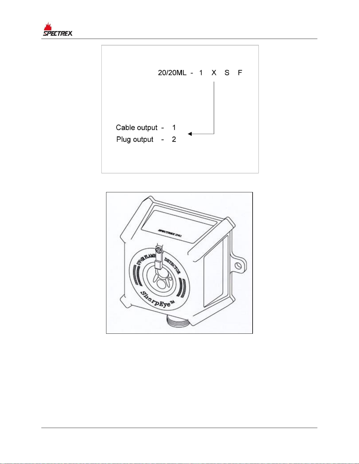
The 20/20ML is available with a St. St. 316L housing.
The output is via either a connector (socket) or a cable tail (up to 2m long).
Page 17
Product Overview
TM767100 Rev. (Ad), May 2019 17
Figure 1: Model Definitions
Figure 2: UV/IR Flame Detector
Page 18
Product Overview
18 SharpEye™ UV/IR Mini Flame Detector User Guide
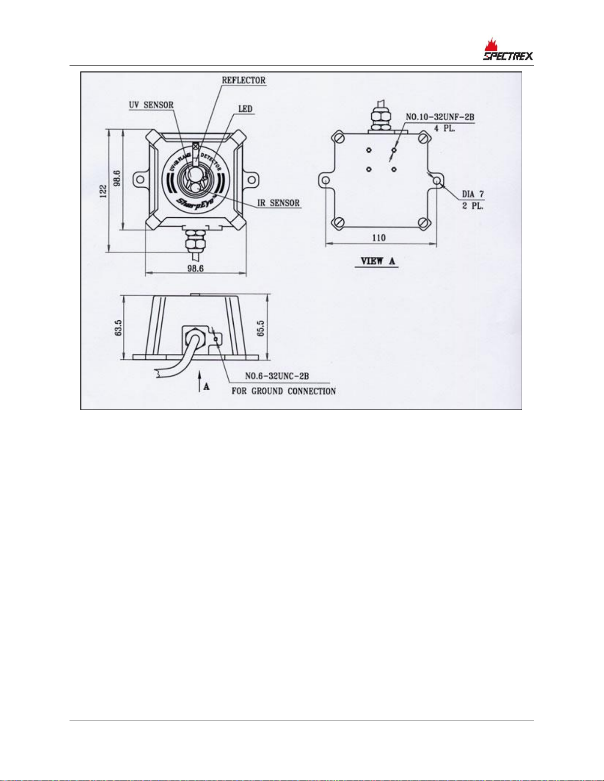
Figure 3: Flame Detector Assembly: Outline Drawing of Cable Output Option
Page 19

Performance
TM767100 Rev. (Ad), May 2019 19
3 Performance
3.1 Detection Sensitivity
Detection sensitivity is the maximum distance at which the detector will reliably
detect a specific size of fire and a typical type of fuel (standard fire).
3.1.1 Standard Fire
A 1ft2/0.1m2 gasoline pan fire with a max. wind speed of 6.5ft/sec / 2m/sec.
3.1.2 Sensitivity Ranges:
The detector has 2 user selectable sensitivity ranges. For each range there are 2
response levels:
• Warning (pre-alarm)
• Alarm
The detection distance for the warning level is approximately 10% higher than
the alarm distance. Alarm response times for a “standard fire” at a specified
range are shown here:
• Sensitivity Range (ft/m): 50/15
• Response Time (sec): 5
For some typical ambient conditions, the Zeta parameter as defined in NFPA 72
for the 20/20ML detector is 0.01 (1/m).
Note:
Zeta parameters may vary significantly with changes in temperature,
air pressure, humidity, visibility conditions, etc.
Page 20

Performance
20 SharpEye™ UV/IR Mini Flame Detector User Guide
3.1.3 Other Fuels
The detector will react to other types of fires as follows:
• Pan fire size: 1ft
2
/0.1m2
• Maximum wind speed: 6.5ft/sec / 2m/sec
• Maximum response time: 10 sec
Table 1: Response Sensitivity Ranges for Other Fuels
Max. Detection Distance
Type Of Fuel
Fire size
20/20ML
(ft/m)
Gasoline
15/50
n-heptane
15/50
Diesel fuel
11/37
JP5
11/37
Kerosene
1ft2/0.1m2 pan fire
11/37
Alcohol (ethanol)
7.5/25
IPA (isopropyl
alcohol)
7.5/25
Methanol
7.5/25
Methane
5/15
LPG (propane)
20”/0.5m plume fire
5/15
Hydrogen
5/15
Silane
12”/0.3m plume fire
5/15
Polypropylene
pellets
8”/0.2m diameter
5/5
Office paper
1ft2/0.1m2 pan fire
4/13
Page 21
Performance
TM767100 Rev. (Ad), May 2019 21
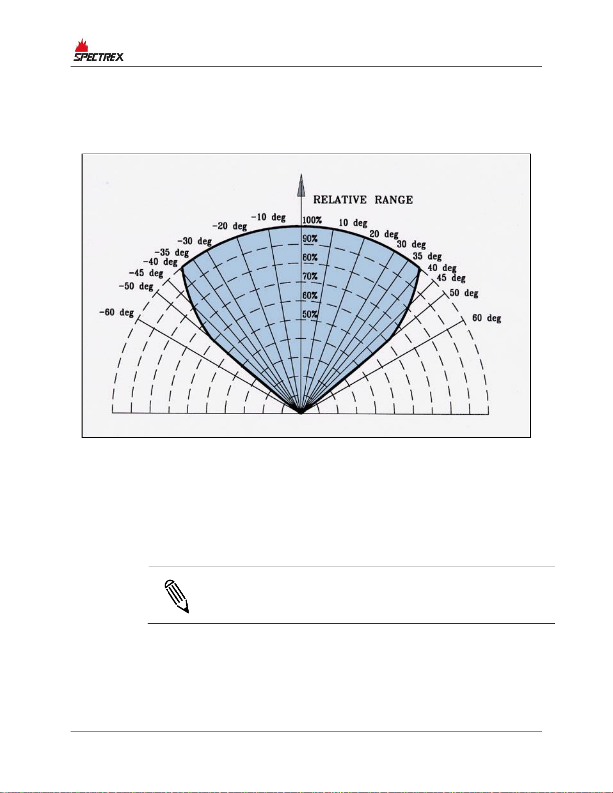
3.2 Cone of Vision
Horizontal: 100°
Vertical: 100°
Figure 4: Horizontal and Vertical Fields of View
3.3 False Alarms Prevention
The detector will not provide an alarm or a warning signal as a reaction to the
radiation sources specified below.
False alarm immunity is listed in Table 2.
Notes:
IAD = Immune at Any Distance
All sources are chopped from 0 to 20Hz
Page 22

Performance
22 SharpEye™ UV/IR Mini Flame Detector User Guide
Table 2: 20/20ML - Immunity to False Alarm Faults
Radiation Source
Immunity
Distance
(ft/m)
Sunlight
IAD
Indirect or reflected sunlight
IAD
Vehicle headlights (low beam) conforming to MS53023-1
IAD
Incandescent frosted glass light, 100W
IAD
Incandescent clear glass light, rough service, 100W
IAD
Fluorescent light with white enamel reflector, standard office
or shop, 40W (or two 20W)
IAD
Arc welding [4mm/ 5/32” rod; 240A]
9.8/3
Bright colored clothing, including red and safety orange
IAD
Electronic flash (180 watt seconds minimum output)
IAD
Red dome light conforming to M251073-1
IAD
Blue-green dome light conforming to M251073-1
IAD
Flashlight (Mx 991/U)
IAD
Radiation heater, 1500W
IAD
Radiation heater, 1000W with fan
IAD
Grinding metal
3.3/1
Lit cigar or cigarette
IAD
Match, wood, and stick, including flare-up
3.3/1
Sunlight
IAD
Sunlight
IAD
Indirect or reflected sunlight
IAD
Vehicle headlights (low beam) conforming to MS53023-1
IAD
Incandescent frosted glass light, 100W
IAD
Page 23
Operation
TM767100 Rev. (Ad), May 2019 23
4 Operation
4.1 Visual Indications
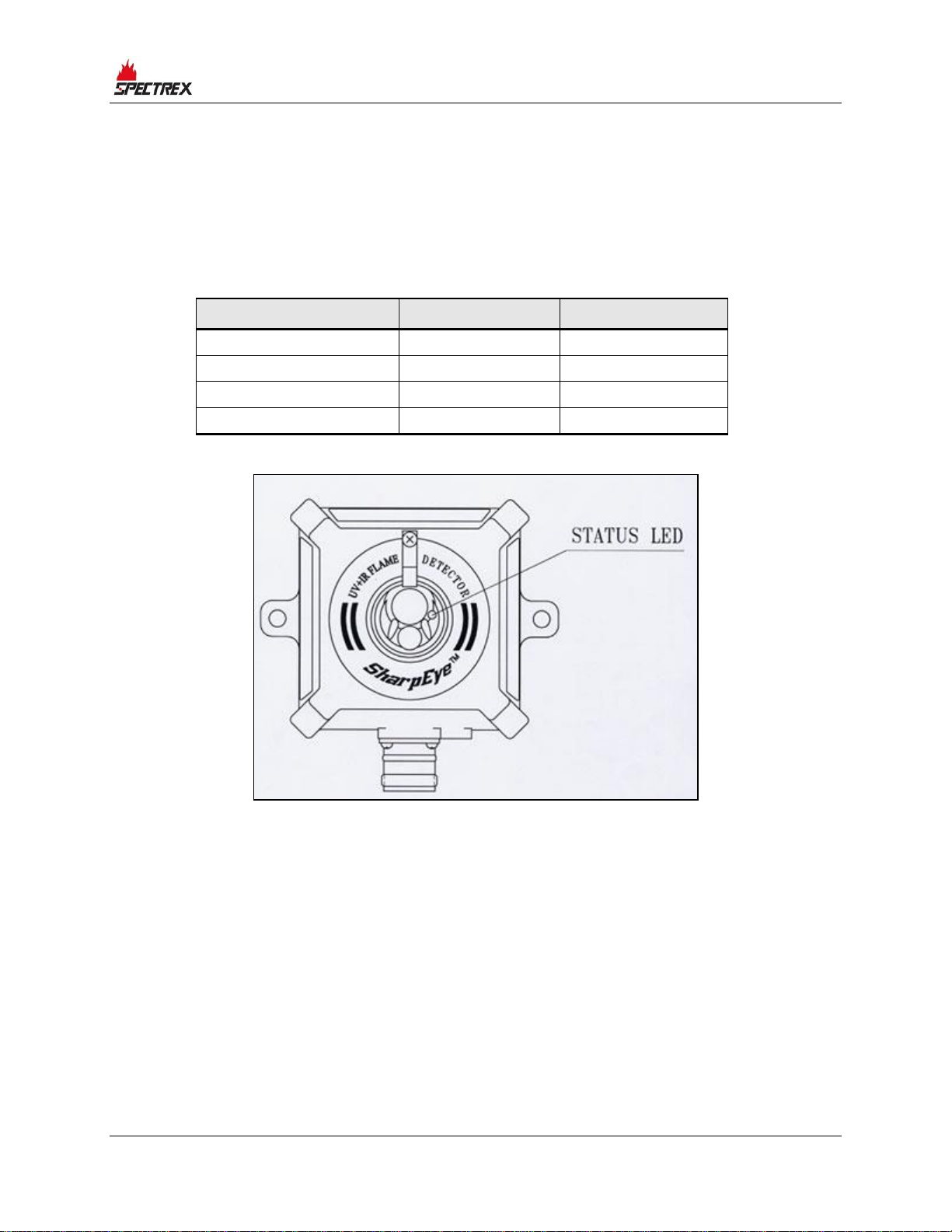
One 3-color LED-indicator is located in the detector front window:
Detector Status
LED Color
LED Mode
Fault, BIT Fault
Yellow
4Hz flashing
Normal
Green
1Hz flashing
Warning
Red
2Hz flashing
Alarm
Red
Steady
Figure 5: 20/20ML LED
4.2 Output Signals
The detector provides the following outputs:
• Alarm relay
• Fault relay
• 4–20mA current output
• RS-485 communications
The detector can be in one of the following states:
Page 24

Operation
24 SharpEye™ UV/IR Mini Flame Detector User Guide
Table 3: Detector States
Detector State
Description
Normal
The detector is functioning normally.
BIT
The detector performs a Built-In-Test.
Warning
Fire detected – warming alarm (pre-alarm) state.
Alarm
Fire detected – fire alarm state.
Latched Alarm
(Optional)
The alarm outputs are latched due to the detection
of a fire that has already been extinguished.
BIT Fault
A fault is detected during a BIT sequence. The
detector will continue to detect fire if the alarm
conditions occur.
Fault
A fault is detected when the power supply is too low
or during a software fault.
In each state, the detector will activate different outputs, as specified in Table 4.
Table 4: Output Signals Versus Detector State
Detector State
Color
LED
Flashing
LED
Alarm
Relay
Fault
Relay
4–20mA
Output
Normal
Green
1Hz
Off
On
4mA
Warning
Red
2Hz
Off
On
16mA
Alarm1
Red
Steady
On
On
20mA
Latch2
Red
Steady
On
On
20mA
BIT Fault3
Yellow
4Hz
Off
Off
2mA
Warning at
BIT Fault
Red
2Hz
Off
Off
16mA
Alarm at BIT
Fault
Red
Steady
On
Off
20mA
Fault
Yellow
4Hz
Off
Off
0mA
1
The Alarm outputs will be activated as long as the alarm conditions are present.
2
The Alarm state can be latched (optional) according to the programmable function.
3
The detector will be in its BIT Fault state until it has passed a successful BIT and will stop
approximately 3 seconds after the fire is no longer detected.
4.2.1 Optional Latching
The detector has an optional latched alarm output capability, which operates
according to the programmable function. If selected, upon the detection of a fire,
the detection signal is latched until manually reset (disconnecting the power
supply or performing a manual BIT). Latching affects the Alarm relay, 4–20mA
output, and the Alarm LED.
Page 25

Operation
TM767100 Rev. (Ad), May 2019 25
4.2.2 Built-In-Test
When the programmable function Alarm BIT is set at Yes, a successful manual
BIT will activate the Alarm relay for 3 seconds and the 4–20mA output will
provide 20mA for 3 seconds
4.3 Detector Mode Setup
4.3.1 Detector Settings
See Detector Default Setup on page 26 for default factory settings.
The 20/20ML incorporates several functions that can be set by the customer
using SPECTREX Host software, which will be supplied for each detector
shipment.
The Host software enables you to change functions, as described in Detector’s
Various Functions on page 25. Refer to Manual TM784050 for programming
instructions.
4.3.2 Detector’s Various Functions
4.3.2.1 Sensitivity Ranges
The detector offers 2 sensitivity settings. The detection distance for the alarm
level is 50ft/15m from a standard fire.
4.3.2.2 Alarm Delay
The detector is equipped with an alarm delay option, which provides
programmable time delays of 0 to 30 seconds with 8 fixed settings: 0, anti-flare,
3, 5, 10, 15, 20, and 30 seconds.
The alarm delay option will affect the alarm relay and the 4–20mA output.
When an alarm (detection) level condition is encountered, the detector delays the
execution of the Alarm output relay by the specified period of time. The detector
will then evaluate the condition for 3 seconds. If the alarm level is still present,
the alarm outputs will be activated. If this condition no longer exists, the detector
will return to its Standby state. The LED will indicate the warning level during the
delay time only if the fire condition exists.
4.3.2.3 Anti-Flare
Anti-Flare mode is selected to prevent false alarms in locations where fast flares
may be present. The time delay for fire alarm in this mode is from 2.5 to 15
seconds (mostly less than 10 seconds).
Page 26

Operation
26 SharpEye™ UV/IR Mini Flame Detector User Guide
Table 5: Time Delay
Delay (seconds)
0
A* – anti-flare
3
5
10
15
20
30
Default
4.3.2.4 Function Setup
The user can select the desired mode of operation by means of the host.
Table 6: Function Setup
Name
Yes
No
Alarm latch
Alarm latching enable
Alarm latching disable
(default)
Automatic
BIT
Automatic and manual
BIT (default)
A manual BIT only
Alarm BIT
A successful manual BIT
activates the alarm relay
for approximately 3
seconds; the 4–20mA
will provide 20mA for 3
seconds
A successful manual BIT
does not activate the alarm
relay (default)
4.3.2.5 Addresses Setup
Refer to TM784050 for instructions for defining the addresses of the detectors.
The detector provides up to 247 addresses (from 1 to 247) that can be used with
an RS-485 communications link.
4.3.3 Detector Default Setup
The detector has 5 functions that can be programmed according to customer
requirements at the factory or at the customer facility using a software host. If
there are no specific requirements, the standard setup (default) that the detector
is programmed to are as follows:
Page 27

Operation
TM767100 Rev. (Ad), May 2019 27
Table 7: Default Function Setup
Detector Default Setup
20/20ML
Delay
3
Alarm Latch
No
Automatic BIT
Yes
Alarm BIT
No
4.4 Built-In-Test
4.4.1 General
The detector’s Built-In-Test (BIT) checks the following:
• Electronic circuitry
• Sensors
• Window cleanliness
The detector can be set to perform the BIT automatically and manually, or
manually only.
4.4.2 Principles
If the result of a BIT is the same as the current status of the detector (Normal or
BIT Fault), the detector’s status is unchanged. If the result of a BIT differs from
the current status of the detector, the detector’s status is changed (from Normal
to BIT Fault or from BIT Fault to Normal).
Note:
In BIT Fault status, the detector can continue to detect a fire.
4.4.3 Automatic and Manual BIT
4.4.3.1 Automatic BIT
The detector automatically performs a BIT every 15 minutes.
A successful BIT does not activate any indicator:
• The fault relay remains closed (Normal).
• The LED continues to flash (1Hz) at green.
• The 4–20mA output continues to indicate 4mA.
An unsuccessful BIT sequence activates the following:
Page 28

Operation
28 SharpEye™ UV/IR Mini Flame Detector User Guide
• The Fault relay is opened.
• 4–20mA output indicates a BIT Fault (2mA).
• The LED flashes (4Hz) at yellow.
• A BIT procedure will be performed every minute.
4.4.3.2 Manual BIT
Functions as described in Manual BIT Only on page 28. In the case of an
unsuccessful BIT, all outputs will function as described in Manual BIT Only; but
the BIT will be automatically executed every minute. This mode of operation will
continue until a successful BIT has been completed. As a result, the detector will
resume its normal operation.
4.4.4 Manual BIT Only
The BIT is initiated manually by momentarily connecting Pin no. 3 (yellow wire)
with Pin no. 2 (black wire). A successful manual BIT activates the following:
• Fault relay remains closed.
• Alarm relay is activated for 3 sec (only when the Function Alarm BIT is at
Yes).
• 4–20 mA output current will be 20mA (only when the Function Alarm BIT is at
Yes).
• The LED will illuminate at red for 3 sec.
An unsuccessful BIT activates the following:
• Fault relay is opened.
• 4–20 mA output indicates BIT fault condition (2mA).
• The LED flashes (4Hz) at yellow.
Note:
During a manual BIT, if the Function Alarm BIT is at Yes, the Alarm
relay will be activated and the 4–20mA outputs will initiate 20mA.
Therefore, automatic extinguishing systems or any external devices
that should be activated under actual alarm conditions should be
disconnected during a BIT.
Page 29
Technical Specifications
TM767100 Rev. (Ad), May 2019 29
5 Technical Specifications
5.1 Electrical Specifications
5.1.1 Operating Voltage
• 18–32 VDC
5.1.2 Power Consumption
• Max. 35mA in Standby
• Max. 80mA in Alarm
5.1.3 Electric Input Protection
The input circuit is protected against voltage-reversed polarity, voltage
transients, surges, and spikes, according to MIL-STD-1275A.
5.1.4 Electrical Outputs
5.1.4.1 Dry Contact Relays
Table 8: Contact Ratings
Relay Name
Type
Normal Position
Maximum Ratings
Alarm
SPST
N.O.
2A at 30VDC
Fault*
SPST
N.C.
2A at 30VDC
The Fault relay will be energized when closed during the detector’s regular operation. The contact
will be open at Fault condition or low voltage.
5.1.4.2 4–20mA Current Output
The 4–20mA is an isolated sink option. The maximum permitted load resistor is
600ohm.
State
20/20ML Output (mA)
To
Fault
0
+0.5mA
BIT Fault
2
±10%
Normal
4
±10%
IR Detect
8
±5%
UV Detect
12
±5%
Warning
16
±5%
Alarm
20
±5%
Page 30

Technical Specifications
30 SharpEye™ UV/IR Mini Flame Detector User Guide
5.2 Communications Network
The detector is equipped with an RS-485 communications link that can be used in
installations with computerized controllers. The communications protocol is
Modbus-compatible.
• This protocol is a standard and is widely used.
• It enables continuous communications between a single standard Modbus
controller (master device) and a serial network of up to 247 detectors.
• It enables connection between different types of SPECTREX detectors or other
Modbus devices to the same network.
5.3 Mechanical Specifications
5.3.1 Enclosure Options
• St. St. 316L electro-chemical and passivation coating
5.3.2 Water and Dust-Tight
• NEMA 250 type 6p
• IP66 and IP67 per EN 60529
5.3.3 Electronic Modules
• Conformal coated
5.3.4 Electrical Connection
• Connector interface (mating connector is supplied with a detector)
• Cable interface
5.3.5 Dimensions
• Base: 4.3”/110mm x 3.9”/100mm
• Height: 2.6”/65.5mm
5.3.6 Weight
• St. St. 316L housing: 2.4lb/1.2kg
• Tilt mount: 0.8lb/0.37kg
5.4 Environmental Specifications
5.4.1 High Temperature
• Design to meet MIL-STD-810C, Method 501.1, Procedure II
• Operating temperature: +160°F/+70°C
• Storage temperature: +185°F/+85°C
Page 31

Technical Specifications
TM767100 Rev. (Ad), May 2019 31
5.4.2 Low Temperature
• Design to meet MIL-STD-810C, Method 502.1, Procedure I
• Operating temperature: -40°F/-40°C
• Storage temperature: -65°F/-55°C
5.4.3 Humidity
• Designed to meet MIL-STD-810C, Method 507.1, Procedure IV
• Relative humidity of up to 95% for the operational temperature range
5.4.4 Salt Fog
• Designed to meet MIL-STD-810C, Method 509.1, Procedure I
• Exposure to a 5% salt solution fog for 48 hours
5.4.5 Dust
• Designed to meet MIL-STD-810C, Method 510.1, Procedure I
• Exposure to a dust concentration of 0.3 frames/ft
2
at a velocity of 1750fpm,
for 12 hours
5.4.6 Vibration
• Designed to meet MIL-STD-810C, Method 514.2, Procedure VIII
• Vibration at an acceleration of 1.1g within the frequency range of 5–30Hz,
and an acceleration of 3g within the frequency range of 30–500Hz
5.4.7 Mechanical Shock
• Designed to meet MIL-STD-810C, Method 516.2, Procedure I
• Mechanical shock of 30g half-sin wave, for 11 msec
5.4.8 Electromagnetic Compatibility (EMC)
This product is in conformance with EMC directive 89/336/EC:
Radiated Emission
EN61000-6-3
Conducted Emission
EN61000-6-3
Radiated Immunity
EN61000-4-3
Conducted Immunity
EN61000-4-6
ESD
EN61000-4-2
Burst
EN61000-4-4
Surge
EN61000-4-5
Page 32

Page 33

Installation Instructions
TM767100 Rev. (Ad), May 2019 33
6 Installation Instructions
6.1 Scope
The SharpEye Model 20/20ML is a self-contained optical flame detector designed
to operate as a stand-alone unit, directly connected to alarm systems or to
automatic fire extinguishing systems. The detector can be part of a more complex
system where many detectors and other devices are integrated through a
common control unit.
This chapter does not attempt to cover all of the standard practices and codes of
installation. Rather, it emphasizes specific points of consideration and provides
some general rules for qualified personnel. Wherever applicable, special safety
precautions are stressed.
6.2 General Considerations
Note:
The detector should be aimed toward the center of the detection zone
and have a completely unobstructed view of the protected area.
Whenever possible, the detector face should be tilted down at a slight
angle to prevent the accumulation of dust and dirt. Do not start an
installation unless all conceivable considerations regarding detector
location have been taken into account.
To ensure optimal performance and an efficient installation, the following
guidelines should be considered:
6.2.1.1 Sensitivity
To determine the level of sensitivity, the following issues should be considered:
• Size of the fire at the determined distance to be detected
• Types of flammable materials
6.2.1.2 Spacing and Location
The number of detectors and their locations in the protected area are affected by:
• Size of the protected area
• Sensitivity of the detectors
• Obstructed lines of sight
• Cone of view of the detectors
Page 34

Installation Instructions
34 SharpEye™ UV/IR Mini Flame Detector User Guide
6.2.1.3 Environment
• Dust, snow, or rain can reduce the detector’s sensitivity and require more
maintenance activities.
• The presence of high intensity flickering of IR sources may affect sensitivity.
6.3 Preparation for Installation
Installation should comply with local codes or NFPA as applicable to flame
detectors. The detector can be installed with the use of general-purpose common
tools and equipment.
1 Verify the appropriate purchase order. Record the detector’s P/N, serial no.,
and the installation date in the appropriate logbook.
2 Open the package prior to detector installation and visually inspect the
detector.
3 Verify that all components required for the detector’s installation are readily
available before commencing the installation. If installation is not completed
in a single session, secure and seal detectors and conduits.
4 For wiring, use color-coded conductors, suitable wire markings, or labels.
12 to 20AWG (0.5mm²–3.5mm²) wires may be used for site wiring. The
selection of wire gauge should be based on the number of detectors used on
the same line and the distance from the control unit, in compliance with
specifications.
6.4 Installation
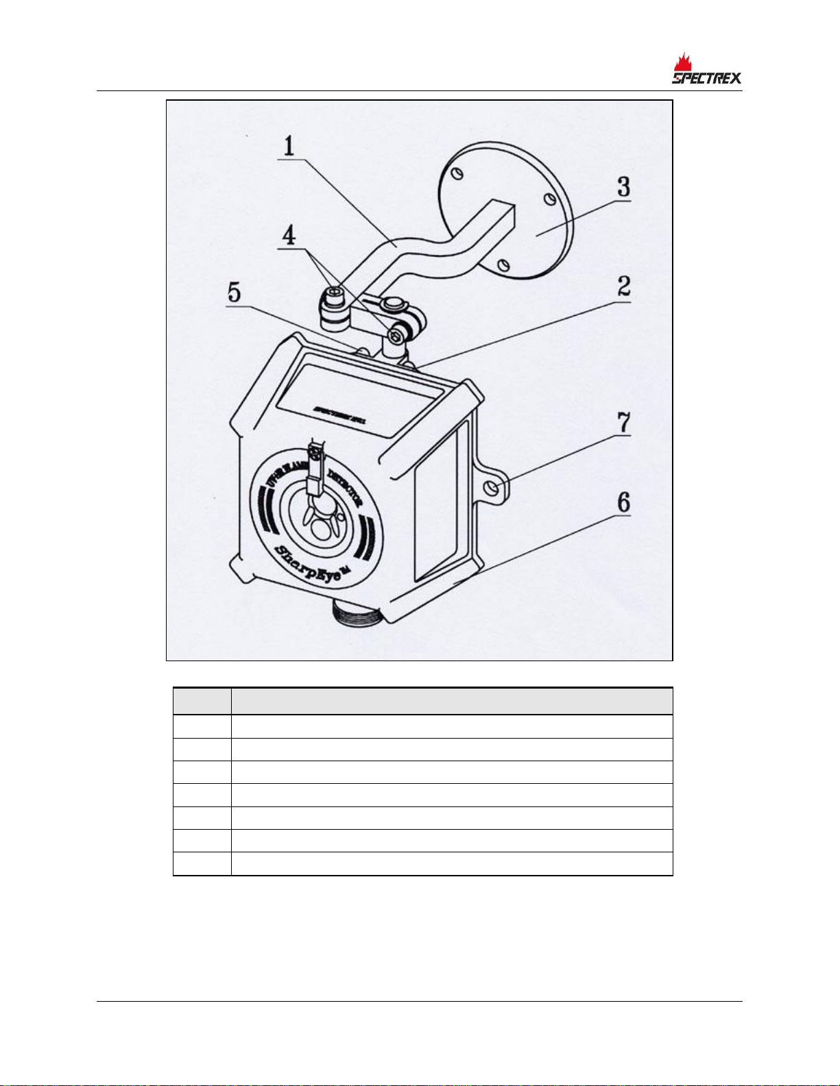
The detector can be mounted directly on the wall through the 7mm hole (Item 7,
Figure 6), or preferably with the optional tilt mount, Model 787640 (Item 1,
Figure 6).
The tilt mount enables the detector to be rotated up to 60 degrees in all
directions.
6.4.1 Tilt Mount Kit
Table 9: Tilt Kit
Item
Qty
Type/Model
Location
Tilt mount P/N 787639
1
787640
Screw
4
10-32 UNF x
7/16”
Detector - holding plate
Spring washer
4
No. 10
Detector - holding plate
Page 35

Installation Instructions
TM767100 Rev. (Ad), May 2019 35
6.4.2 Tilt Installation
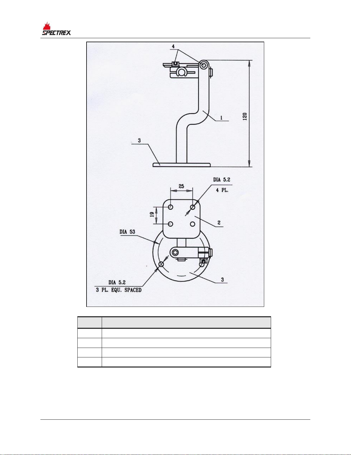
For tilt installation, see Figure 6 and Figure 7.
1 Place the tilt mount (Item 1) in its designated location and secure it with 3
fasteners through 3 holes of dia. 5.2mm.
Note:
Skip this step if the tilt mount is already installed. Also, detector
removal does not require tilt mount removal for maintenance
purposes.
2 Unpack the detector.
3 Place the detector, with its connector or cable pointing down, on the holding
plate of the tilt mount (Item 2). Secure the detector to the tilt mount using
four 10-32 UNF x 7/16” screws with no. 10 spring washers. Use a 5/32 Hex
key for 10-32 screws (Item 5).
4 Release the locking screw (Item 4) in such a way that allows for rotation of
the detector. Point the detector towards the protected area and make certain
that the view of the area is unobstructed. Secure the detector in that position
by tightening the locking screws (Item 4) on the tilt mount. (Make sure the
detector is in the correct position.)
The detector is now correctly located, aligned, and ready to be connected to
the system.
Page 36
Installation Instructions
36 SharpEye™ UV/IR Mini Flame Detector User Guide
Item
Description
1
Tilt mount plate
2
Detector holding plate
3
Mounting plate
4
Locking screw
5
Holding screws
6
Washers
7
IR detector direct mounting holes
Figure 6: Detector and Tilt Mount Assembly
Page 37
Installation Instructions
TM767100 Rev. (Ad), May 2019 37
Item
Description
1
Tilt mount
2
Detector holding plate
3
Mounting plate
Locking screw
Figure 7: Tilt Mount Assembly - Outline Drawing
Page 38

Installation Instructions
38 SharpEye™ UV/IR Mini Flame Detector User Guide
6.5 Detector Mounting
These detectors are not approved for location in hazardous classified areas.
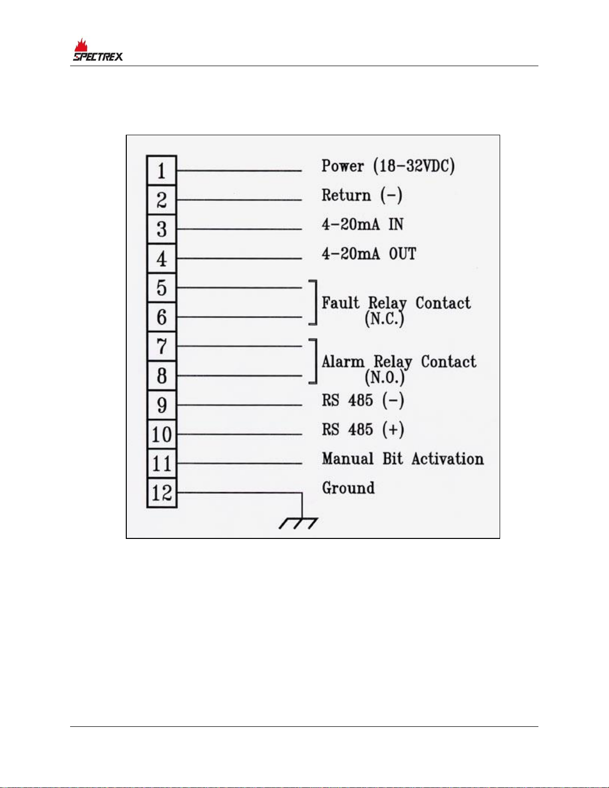
1 Choose the wiring configuration according to Appendix A: on page 47.
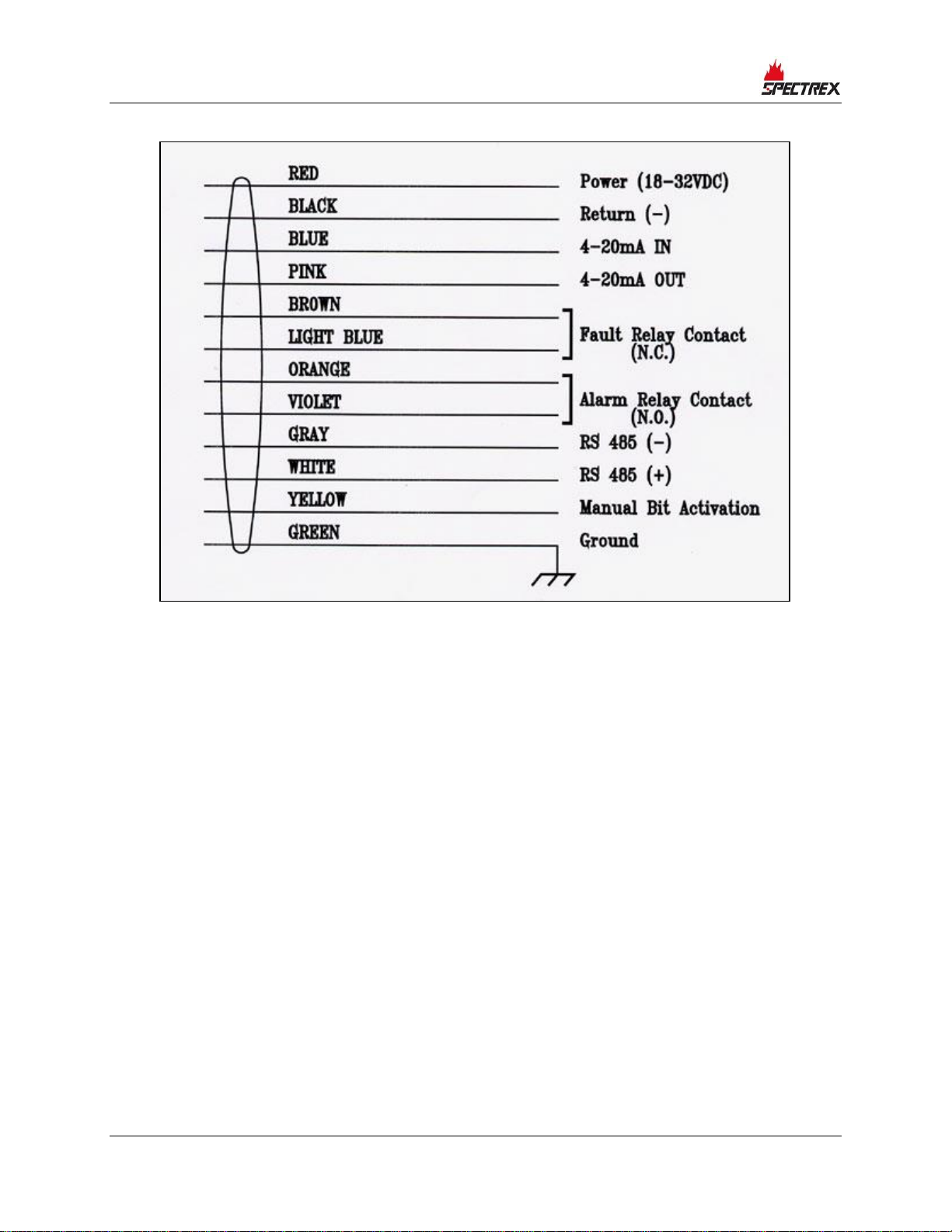
2 Connect the wire to the required PIN on the connector or choose the required
color on the cable, according to your wiring diagram.
3 Connect the grounding wire to the general screw outside the detector (Figure
2 and Figure 3). The detector must be well grounded to earth ground for
proper operation.
6.6 Wiring Function
The following describes the function of each electrical wire of the detector (see
Figure 8 and Figure 9):
6.6.1 Power Supply
• Pin no. 1 (red wire) - input power
• Pin no. 2 (black wire) - return
6.6.2 Manual Bit Activation
• Pin no. 11 (yellow wire) - manual BIT activation.
The manual BIT is initiated by a momentary connection of the Pin no. 11
(yellow wire) to the power supply return line.
6.6.3 Fault Relay
The Fault output is a N.C. SPST contact relay:
• Pin no. 5 (brown wire)
• Pin no. 6 (light blue wire)
The contact is normally energized closed when the detector is in its normal
operational condition.
6.6.4 Alarm Relay
The Alarm output is a N.O. SPST contact relay:
• Pin no. 7 (orange wire)
• Pin no. 8 (violet wire)
Page 39

Installation Instructions
TM767100 Rev. (Ad), May 2019 39
6.6.5 4–20mA Output
This output is used for analog, 4–20mA current output as specified in Electrical
Specifications on page 29:
• Pin no. 11 (pink wire) - output (+)
• Pin no. 12 (blue wire) - input (-)
See Appendix A: on page 47 for more details.
6.6.6 RS-485
This output is used for the communications network as specified in Appendix A:
on page 47.
• Pin no. 10 (white wire) - positive (+) lead
• Pin no. 9 (gray wire) - negative (-) lead
6.6.7 Ground
• Pin no. 12 (green wire) - ground connection
6.7 Operation Mode
The detector is supplied with a default function setup (see Table 7). The function
setup can be reprogrammed by the user through RS-485 using a PC with
SPECTREX host software or through use of a handheld unit. Refer to TM784050
for instructions.
6.7.1 Programmable Function
Modes of operation are programmable with a PC or handheld unit according to
the selection table in Detector’s Various Functions on page 25. Refer also to
TM784050.
6.7.2 Address
The detector has the capability of acting as an addressable device.
The detector provides 247 addresses, which can be used by the RS-485
communications link as described in Function Setup on page 26. Refer also to
TM784050.
6.7.3 Alarm Delay
An alarm delay may be required for certain applications. The detector has an
alarm delay that permits time delays from 0, anti-flare, 3, 5, 10, 15, 20, and 30
seconds respectively. The delay can be defined by the RS-485.
Refer also to TM784050.
Page 40

Page 41

Operating Instructions
TM767100 Rev. (Ad), May 2019 41
7 Operating Instructions
7.1 Scope
The following instructions are designed to obtain optimal performance from the
detector over its lifecycle.
7.2 Power-Up
1 Turn on the detector and wait approximately 60 seconds for the detector’s
automatic self-test.
Note:
Turning on the detector initiates the following sequence:
• The LED flashes (4Hz) yellow
• A BIT is executed
If successful:
• The LED flashes (1Hz) green
• Fault relay contacts close
2 Wiring Inspection: If a short circuit or line discontinuity exists, indications
appear on the control unit display panel. Review your wiring.
3 The detector goes into its Fault state when supply voltage drops below 16.5V.
The detector status goes back to Normal when the supply voltage is above
17.5V.
4 Detector inspection: Visually inspect the detector’s viewing window. It
should be clean and clear.
• LED should flash (1Hz) green
• Alarm relays should be N.O.
• Fault relay should be N.C.
• The 4–20mA output should be 4mA
5 If any of the outputs or indications is different from the description in step 4,
see Troubleshooting on page 46.
The flame detector is now ready for functional testing.
Page 42
Operating Instructions
42 SharpEye™ UV/IR Mini Flame Detector User Guide
7.3 Reset
To reset a detector when in its Alarm state:
• Disconnect power
Or
• Initiate a manual BIT
Caution:
Reset only when the optional latching alarm has been selected.
7.4 Functional Testing
Following is a testing procedure for proper functioning of the detector. The
detector can be tested using the manual Built-in-Test or the SPECTREX Flame
Simulator FS-1200.
7.4.1 Manual BIT Test
Momentarily connecting Pin no. 11 (yellow wire) with Pin no. 2 (black wire)
performs a manual BIT.
Caution:
If the function setup Alarm BIT is at Yes, then the Alarm and 4–20mA
output will be activated during a manual BIT. Therefore, automatic
extinguishing systems or any external devices that may be activated
during BIT must be disconnected.
1 Verify that the detector is operating properly.
2 Initiate a manual BIT. After a few seconds the following occurs:
• An Alarm relay will be activated and the 4–20mA output changes to 20mA
for 3 seconds (only if Alarm BIT is at Yes).
• The LED should be a constant red for 3 seconds.
• The Fault relay should stay N.O. during the test.
7.4.2 Testing with Flame Simulator Model FS1200
This test simulates an exposure of the detector to a real fire condition (see
Appendix B:) using Flame Simulator Model FS1200. The detector is exposed to
radiation at the required detection level. As a result, the detector must generate
a fire alarm signal.
Page 43

Operating Instructions
TM767100 Rev. (Ad), May 2019 43
Note:
If the detector is exposed to a flame simulator, the Alarm relay and
4–20mA will be activated during the simulation. Therefore, automatic
extinguishing systems or any external devices, which may be
activated during this process, must be disconnected.
1 Turn on the system and wait up to 60 seconds for the detector to turn to
Normal state and the LED to flash (1Hz) green. If the detector is on, skip this
step.
2 Aim the SPECTREX Flame Simulator Model FS1200 at the detector’s target
point (see Figure 15), in a way that the radiation emitted by it is facing
directly towards the detector. (See Flame Simulator FS-1200 on page 53).
3 Press the operation button once. After few seconds:
• The LED should light a steady red for a few seconds.
• The 4–20mA output should turn to 20mA for a few seconds and then
return to 4mA.
• The Alarm relay should also turn on during this period.
This completes the installation procedure. The detector and system are now
ready for operation.
7.5 Safety Precautions
After powering up, the detector requires hardly any attention in order to function
properly, but the following should be noted:
• Follow the instructions in the user guide and refer to the drawings and
specifications issued by the manufacturer.
• Do not expose the detector to radiation of any kind unless required for testing
purposes.
• Do not open the detector housing while power is supplied.
• Do not touch internal parts other than the 3 functional switches. Interference
with internal circuits may impair detector performance and will invalidate the
manufacturer’s warranty.
Disconnect external devices, such as automatic extinguishing systems, before
carrying out any maintenance.
Page 44

Page 45

Maintenance Instructions
TM767100 Rev. (Ad), May 2019 45
8 Maintenance Instructions
8.1 Scope
This chapter deals with preventive maintenance, describes possible faults in
detector operation, and indicates corrective measures. Ignoring these instructions
may cause problems with the detector and may invalidate the warranty.
Whenever a unit requires service, please contact the manufacturer or its
authorized distributor for assistance.
8.2 Maintenance Instrumentation and Personnel
Detector maintenance requires ordinary tools and suitably qualified personnel,
who should be familiar with local codes and practices.
8.3 Preventive Maintenance Procedures
The detector must be kept as clean as possible. The detector’s viewing window
and the reflector must be cleaned periodically. The frequency of cleaning
operations depends on the environmental conditions and specific applications.
The fire detection system designer will give his or her recommendations.
1 Disconnect power to the detector before proceeding with any maintenance
including lens cleaning.
2 To clean the detector viewing window and reflector, use water and detergent
and then rinse with clean water.
3 Where dust, dirt, or moisture accumulates on the window, first clean with a
soft optical cloth and detergent then rinse with clean water.
8.4 Periodic Maintenance Procedures
In addition to preventive cleaning and maintenance, the detector should be
functionally tested every 6 months. This test should also be carried out if, for any
reason, the detector has been opened.
8.4.1 Power-Up Procedure
Perform the power-up procedure every time power is restored to the system.
Follow the instructions in Power-Up on page 41.
8.4.2 Functional Test Procedure
Perform a functional test of the detector, as described in Functional Testing on
page 42.
Page 46

Maintenance Instructions
46 SharpEye™ UV/IR Mini Flame Detector User Guide
8.5 Maintenance Records
It is recommended to record maintenance operations performed on a detector in
a system logbook. The record should include information that identifies the unit,
the installation date, contractor, and entries for every maintenance operation
performed including the description of the operation, date, and personnel ID. If a
unit is sent to the manufacturer or distributor for service, a copy of the
maintenance records should accompany it.
8.6 Troubleshooting
8.6.1 Fault Indication
1 Check power supply for correct voltage, polarity, and wiring.
2 Check detector window and reflector for cleanliness. If necessary, clean the
window, as indicated in Preventive Maintenance Procedures on page 45, and
repeat the test.
3 Disconnect the power supply to the system and check the detector's internal
wiring.
4 Reconnect power supply and wait approximately 60 seconds. Repeat the test.
If the indicator LED is still flashing (4Hz) yellow, the unit requires service.
8.6.2 False Alarm or Warning Indication
5 Disconnect the power supply from the system and check internal wiring.
6 Reconnect the power supply and wait approximately 60 seconds. If the
indication remains, the unit requires service.
Page 47
Typical Wiring Configurations
TM767100 Rev. (Ad), May 2019 47
Appendix A: Typical Wiring Configurations
Figure 8: Connector Interface Option
Page 48
Typical Wiring Configurations
48 SharpEye™ UV/IR Mini Flame Detector User Guide
Figure 9: Cable Interface Option
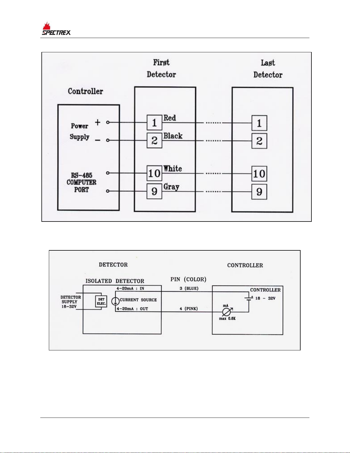
A.1 RS-485 Communications Network
Using the RS-485 network capability of the IR detector and control software, it is
possible to connect up to 32 detectors in an addressable system with 4 wires only
(2 for power and 2 for communications). Using repeaters, the number of
detectors can be much larger (32 detectors for each repeater); up to 247 on the
same 4 wires. When using the RS-485 network, it is possible to read each
detector status (Fault, Warning, and Alarm) and to initiate a BIT for each detector
individually.
For more details, consult the factory.
Page 49
Typical Wiring Configurations
TM767100 Rev. (Ad), May 2019 49
Figure 10: RS-485 Networking
Figure 11: 4–20mA Wiring (Sink Option)
Page 50
Typical Wiring Configurations
50 SharpEye™ UV/IR Mini Flame Detector User Guide
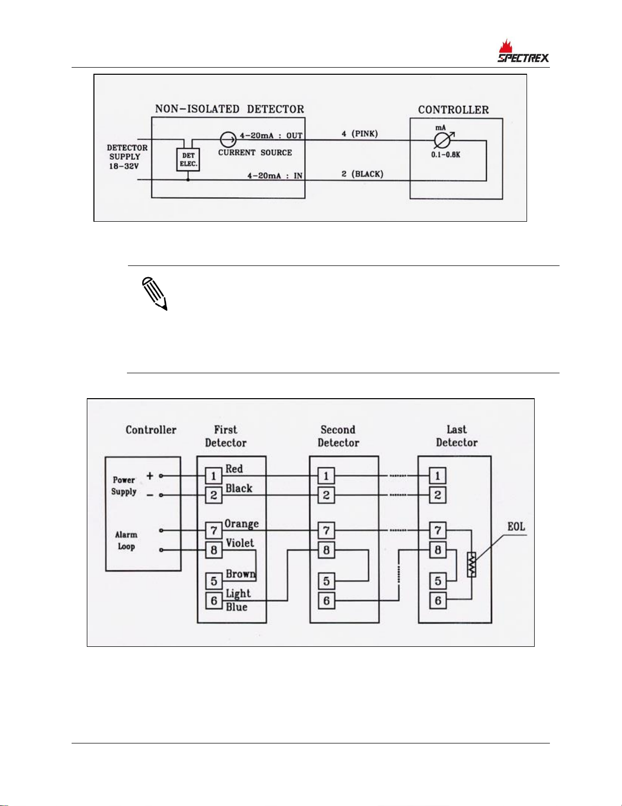
Figure 12: 4–20mA Wiring (Source Option)
Notes:
• The detectors are factory set to isolated 4-20mA-sink version.
• To work at non-isolated 4–20mA source version, connect Pin 3
(blue wire) to Pin 1 (red wire). This can be done on the mating
connector or in the junction box in the cable option.
• The 4–20mA will be measured between Pin 4 (pink wire) and Pin 2
(black wire).
Figure 13: Typical Wiring for 4 Wire Controllers
Page 51

Typical Wiring Configurations
TM767100 Rev. (Ad), May 2019 51
Notes:
• For EOL resistor value, see the Controller Manual.
• The color wire refers to the color of the cable output option. The
Pin no. refers to the connector option
.
Page 52

Page 53
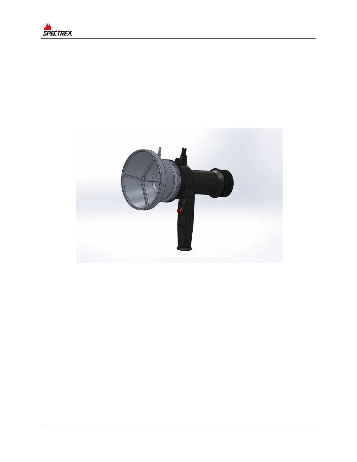
Flame Simulator FS-1200
TM767100 Rev. (Ad), May 2019 53
Appendix B: Flame Simulator FS-1200
The Flame Simulator FS-1200 is designed specifically for use with SharpEye flame
detectors.
The FS-1200 includes a halogen lamp that emits UV and IR energy. This energy
is accumulated by a reflector directed towards the detector, which allows the
detectors to be tested under simulated fire conditions without the associated risks
of an open flame.
Figure 14: SharpEye Flame Simulator FS-1200
Page 54

Page 55
Ordering Information
TM767100 Rev. (Ad), May 2019 55
Appendix C: Ordering Information
The P/N of the Flame Simulator Kit is 380114-2.
The kit is supplied in a carry case that includes:
• Flame Simulator FS-1200
• Charger
• Tool Kit
• Technical Manual TM380102
C.1 Unpacking
Verify that you have received the following contents:
• Delivery form
• Flame simulator with integral battery
• Battery charger
• Tool keys
• User manual
• FAT forms
• EU declaration
• Storage case
C.2 Operating Instructions
Warning:
Do not open the flame simulator to charge the batteries or for any
other reason in a hazardous area.
Caution:
The following test simulates a real fire condition and may activate the
extinguishing system or other alarms. If activation is not desired,
disconnect/inhibit them before the test and reconnect after the
simulation.
Page 56
Ordering Information
56 SharpEye™ UV/IR Mini Flame Detector User Guide
To simulate a fire:
1 Verify you are at the correct distance from the detector according to the type
of detector and the detector sensitivity.
2 Using the mechanical sight, aim the flame simulator toward the center of the
detector.
3 Push the activate button, and then use the laser spot for fine adjustment
toward the center of the detector.
4 Keep the simulator aimed at the detector for up to 50 seconds, until you
trigger an alarm.
C.2.1 Range
Table 10: Sensitivity Ranges
Detector
Types
Detector Sensitivity Setting
(ft/m)
Maximum Testing
Distance (ft/m)
20/20ML
50/15
20/6
Notes:
• The minimum distance from the detector is 20”/50cm.
• At extreme temperatures, there is a 15% maximum reduction in
the range.
Caution:
Store the flame simulator in a safe place when not in use.
C.2.2 Charging the Battery
The flame simulator uses lithium-ion batteries as a rechargeable power source.
When the batteries are fully charged, the simulator operates at least 1,000 times
without having to be recharged. The simulator will not operate when the voltage
from the batteries is lower than the required operational level.
Page 57
Ordering Information
TM767100 Rev. (Ad), May 2019 57
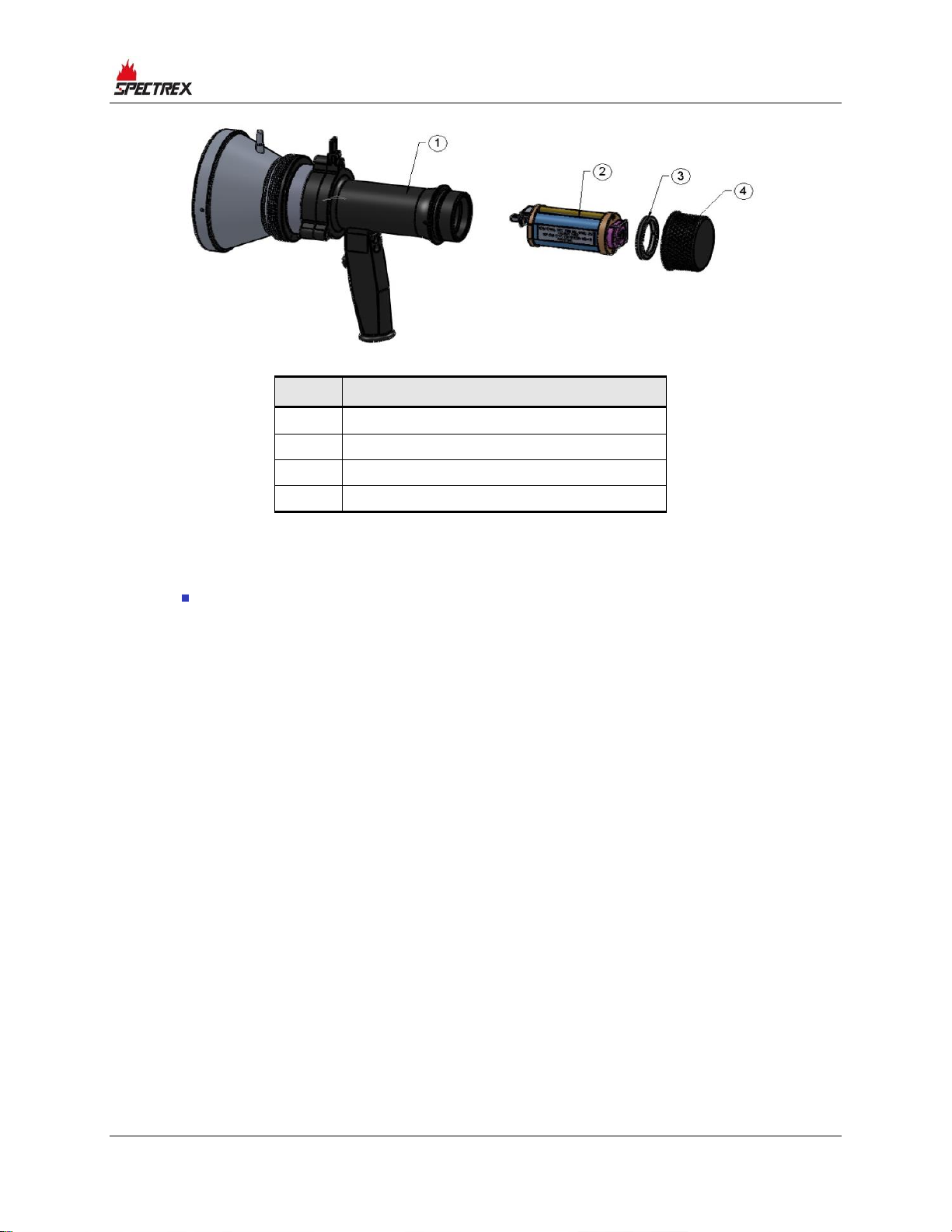
Item
Description
1
Simulator
2
Battery pack
3
Locking disc
4
Back cover
Figure 15: Flame Simulator Battery Replacement
To charge the battery:
1 Place the flame simulator on a table in a safe area, not exceeding
104°F/40°C.
2 Release the locking screw.
3 Unscrew the battery back cover (Item 4) counterclockwise.
4 Unscrew the locking disc (Item 3) clockwise.
5 Pull out the battery from the flame simulator.
6 Connect the battery to the charger. Verify that the charger is the one supplied
with the flame simulator model FRIWO MPP15 with a maximum charging
voltage of 16.8V (4.2V x 4), and with a maximum current of 700mA.
7 Charge for a maximum of 2–3 hours, until the green LED on the charger turns
on.
8 Disconnect the charger.
9 Insert the battery into the flame simulator.
10 Screw on the locking disc (Item 3).
11 Screw on the back cover (Item 4).
12 Lock the back cover with the locking screw.
Page 58

Ordering Information
58 SharpEye™ UV/IR Mini Flame Detector User Guide
C.2.3 Replacing the Battery
To replace the battery:
1 Place the flame simulator on a table in a safe area, not exceeding
104°F/40°C.
2 Release the locking screw.
3 Unscrew the battery back cover (Item 4) counterclockwise.
4 Unscrew the locking disc (Item 3) clockwise.
5 Pull out the battery from the flame simulator.
6 Insert the new battery pack in the simulator housing. Use only the SPECTREX
battery pack, P/N 380004.
7 Screw on the locking disc (Item 3).
8 Screw on the back cover (Item 4).
9 Lock the back cover with the locking screw.
For more information, refer to TM380002.
C.3 Technical Specifications
C.3.1 General
• Temperature Range: –4°F to +122ºF / –20ºC to +50ºC
• Vibration Protection: 1g (10–50Hz)
C.3.2 Electrical
• Power: 14.8V (4 x 3.7V rechargeable lithium-ion battery)
• Max. current: 4A
• Battery capacity: 2.2AH
• Charging time: 2A at 2hr
C.3.3 Physical
• Dimensions: 230 x 185 x 136mm
• Weight: 5.5lb/2.5kg
• Enclosure: aluminum, heavy-duty, copper-free black zinc coating.
Page 59
Ordering Information
TM767100 Rev. (Ad), May 2019 59
• Explosion proof enclosure:
• ATEX and IECEx
• Ex II 2 G D
• Ex d ib op is IIB +H2 T5 Gb
• –20°C to +50°C / –4°F to +122°F
C.3.4 EMI Compatibility
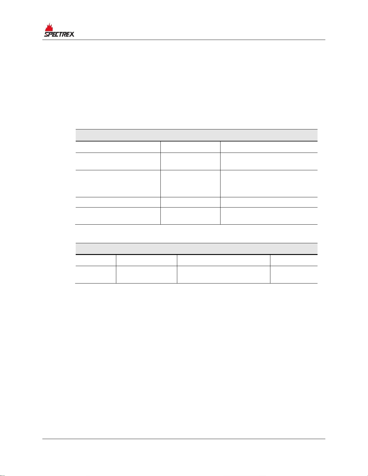
Table 11: Immunity Tests
Immunity Tests
Title
Basic Standard
Level to be Tested
Electrostatic Discharge
(ESD)
IEC 61000-4-2
6kV/8kV contact/air
Radiated Electromagnetic
Field
IEC 61000-4-3
20V/m (80MHz–1GHz)
10V/m (1.4–2GHz)
3V/m (2.0–2.7GHz)
Conducted Disturbances
IEC 61000-4-6
10Vrms (150kHz–80MHz)
Immunity to Main Supply
Voltage Variations
MIL-STD-1275B
Table 12: Emission Tests
Emission Tests
Title
Basic Standard
Level to be Tested
Class
Radiated
Emission
IEC 61000-6-3
40dbuv/m (30–230MHz),
47dbuv/m (230MHz–1GHz)
Like Class B
of EN 55022
Page 60

Page 61

Page 62

Page 63

Page 64

Technical Support
For technical assistance or support, contact:
8200 Market Blvd
Chanhassen, MN 55317
USA
Phone: +1 (973) 239 8398
Fax: +1 (973) 239 7614
Email: [email protected]
Website: www.spectrex.net
 Loading...