

Page 1

November 2015_JS
DG813 & DG613
Pipe Laser
How to use the pipe lasers – step by step
Page 2

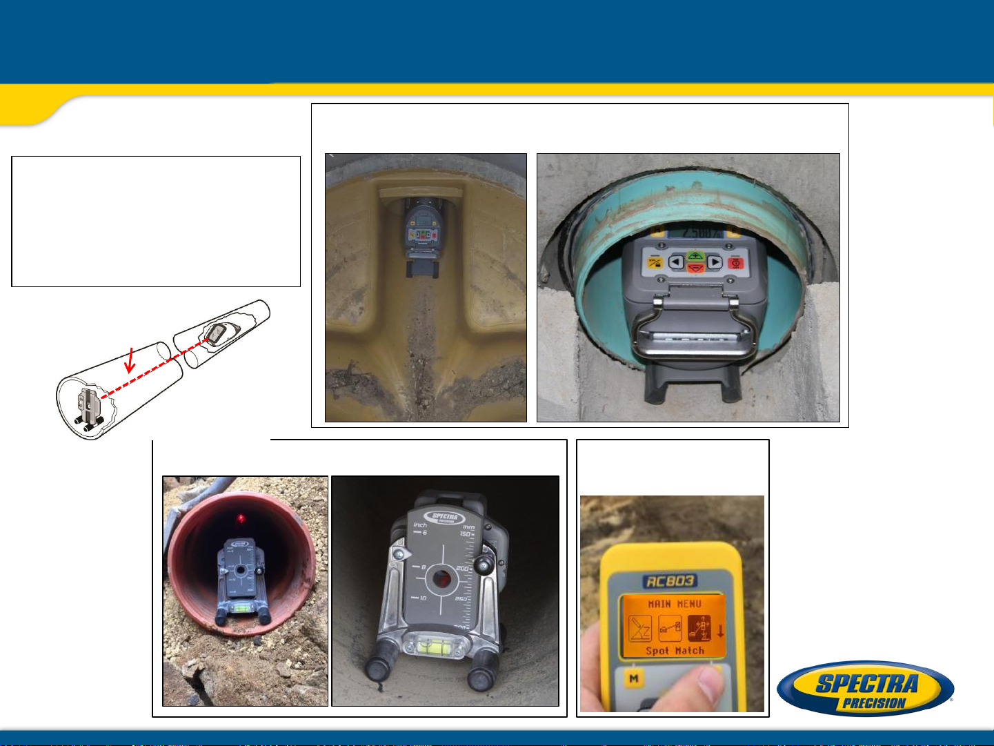
DG813/DG613 Components
DG813
DG613
SF803
RC803 Recharge kit
Page 3

Powering the Laser
1 – DG’s are shipped with a rechargeable
NiMH battery pack (Q104667).
Only the original rechargeable battery
pack allows charging with the
provided charger.
2 – An optional external charger Cable,
12V Battery w/Cigarette Lighter Plug
(P25) is also available
3 – Alkaline batteries can be used as a
backup
4 – Plus and minus symbols indicate
how to put the alkaline batteries into
the battery compartment
Page 4

Installing Batteries
- Open the battery door by pulling out
the battery door latches.
- Push down the battery door and lift up
the locking lever that has the
two pins
- Insert batteries (or a rechargeable
battery pack) into the housing so
that the negative poles are on the
bigger battery spiral springs.
- Close the battery door and lock it by
pushing the door latches back to the
housing.
Page 5

Powering the Remote Control RC803
1. Open the battery door using a coin or similar
pry device to release the battery door tab on
the RC803.
RC803 will be shipped with alkaline batteries
Rechargeable batteries can be used optional
but need to be charged externally.
2. Insert two AA batteries noting the plus (+)
and minus (-) diagrams inside the battery
housing.
3. Close the battery door. Push down until it
“clicks” into the locked position.
Page 6

Using the Remote Control RC803
1. Press the button to turn on the Radio/IR
remote control.
If the RC803 is outside the radio operating range
the remote switches automatically into the IR
connection capability.
Note: When the remote control is initially turned
on, the standard display (model number and
software version) appear for the first 3 seconds,
then the grade value and line direction
indications briefly appear in the LCD.
With every button press, the LCD backlight is
activated and turns off automatically if no button
is pressed for 8 seconds.
To turn off the radio remote control, press and
hold the button for two seconds.
Note: 5 minutes after the last button press, the
remote control turns off automatically.
Page 7

Powering the Spot Finder SF803
1. Open the battery door pulling the battery
door latch.
The SF803 will be shipped with 4 AA
alkaline batteries.
Rechargeable batteries can be used
optional but need to be charged externally.
2. Insert four AA batteries noting the plus (+)
and minus (-) diagrams inside on the
battery door.
3. Close the battery door. Push down until it
“clicks” into the locked position.
Page 8

Components Spot Finder SF803
13 12
5
9
7 3
6
5
8
1
10
11
1 - SF803
2 - Target Plate
for Spot Finder
3 - Center Hole
4 - Power Button
5 - Bubble Vial
4
6 - Battery LED
10
7 - Mode LED
8 - Red Direction LEDs
9 - IR transmitters/receivers
10 - Marking notches (front and back)
11 - M6 Clamp Mount
12 - Battery door
13 - Latch for Battery Door
14 - Release Tab Target Plate
15 - SF Pole Adapter
2
14
15
Page 9

DG813/DG613 Components
1. Battery Compartment – holds the
NiMH battery pack. (D-Cell alkaline
batteries can be used as a backup.)
2. Battery Door Latches – locks/unlocks
and holds the battery compartment in
place.
3. LCD Graphic Display - shows the power,
grade, battery, out-of-level, beam position,
menu information and status of the laser.
4. Grade Axis Pivot Marker - identifies the
pivot point for the grade system
5. Line-Axis Pivot Marker and LED - used
to align a transit over the top of the laser;
lights for 15 minutes after turning on the
laser or pressing one of the buttons.
6. Handle - to carry the laser easily
5
4
3
2
6
1
and to attach a safety rope in manholes
with water.
Page 10

DG813/DG613 Components
7. Axis Alignment Markers - used to align
7
the laser when the line system is centered.
8. Mounts for scope adapter – to
attach the optional scope adapter for the
„Over the Top“ application
9. 5/8”-11 Threaded Mount – to attach the
laser to various setup accessories
10. Remote Receiver Window – receives
signals from the RC803 and SF803
11. Beam-Exit Window – provides a
clear window for the laser beam to exit
the pipe laser.
8
9
10
11
Page 11

DG813/DG613 Controls
12. Power Button - turns the laser On/Off
(To turn off the laser, press and hold the button
for 2 seconds).
13. M – Menu Button - Quickly press and release
starts the menu entry. Use the +/- and Left/Right
buttons to toggle through the menu.
14. E - Enter Button - Quickly press and release
to activate a selected menu function and show
the actual laser and remote control battery
status.
15. Escape/Lock (ESC) Button - If pressed
simultaneously with one of the left/right or +/-
buttons, it locks/unlocks the +/- or the left/right
buttons, so that the unit can’t be unintentionally
changed.
If pressed for 5 seconds, the unit switches
to the manual mode (steep grade).
13
15
14
12
Page 12

DG813/DG613 Controls
16. Left Line Control Button - moves the laser
beam to the left.
(Simultaneously pressed with the Right Line
Button, centers the line.)
17. Plus Button - increases the grade.
(Press and hold this button simultaneously with
the Minus button to zero the grade when in
Step & Go mode.)
18. Minus Button - decreases the grade.
(Press and hold this button simultaneously with
the Plus button to zero the grade when in
Step & Go mode.)
19. Right Line Control Button - moves the laser
beam to the right.
(Simultaneously pressed with the Left Line
Button, centers the line.)
16
17
18
19
Page 13

SF803 – Controls, Features and Functions
1. Power Button:
Press and release the button to turn ON the SF803.
All display LED’s will light for 1.0 sec.
Press and hold button for >2 sec. to turn OFF the
Spot Finder.
2. Battery LED:
solid green when SF803 is on and batteries are OK
blinking red if battery voltage is 3,8V<V bat <4V
solid red if battery voltage is <3,8V; SF803 turns off
automatically after 5 min.
3. Mode LED:
4
3
2
1
yellow solid: paired and radio connection OK
yellow flashing: none or lost radio signal
4. Red Direction LEDs:
Spot Search mode: pointing towards the center of the
beam.
All 4 LEDs are solid red when the SF803 is centered
at the beam.
Automatic SpotLok mode: solid for 5 min.,
then the LED’s flash every 5 seconds.
Page 14

Pairing DG813/DG613 with RC803
First, make sure the transmitter and the remote control are turned off. Then press and hold
the button and turn on the transmitter. During the next 6 seconds (the red LED
flashes fast while the display shows Pairing repeat the same steps on the
remote control.
The remote’s display show Pairing OK for one second and then the same
function as the laser is actually working to indicate the transmitter has been matched with
the remote control.
1
2
O
O
+
+
I
I
Page 15

Pairing DG813 with SF803
First, make sure the transmitter and the Spot Finder are turned off.
Then press and hold the button and turn on the transmitter.
During the next 6 seconds (the red LED flashes fast while the display shows Pairing.
Turn On the Spot Finder; the SF803 pairs now automatically with the transmitter.
After a successful pairing, the Laser shows the standard display while the yellow SF803
LED is solid.
1
2
O
O
+
I
I
Page 16

DG813/DG613 Setup
Position the laser at the manhole invert or on bottom of the trench at the desired elevation.
Press the power button to turn On the laser.
The LCD shows Initialization for one second, then the model number (red and green LEDs are on
for one second - diagnostic mode).
The standard display appears and the temperature/reference check
will start while the thermometer symbol is flashing.
Don‘t start automatic functions at the menu before the reference check has been finished.
If an automatic function will be selected and then confirmed with the button during the
reference check, the display shows the reference check is still running.
Page 17

DG813/DG613 Setup
The unit starts the self-leveling when the temperature check has been completed indicated by
the flashing beam and flashing vial symbol at the display.
The unit is leveled when the laser beam is no longer flashing
(once every second).
If the laser is positioned beyond its self-leveling range of -12% to + 40%,
the laser beam remains flashing.
Note: If the laser can’t level during two minutes, the error message 141 “Time Out” appears.
Reposition the laser within its self-leveling range.
The laser’s cross axis is completely compensated over the entire roll range.
Page 18

DG813/DG613 Setup
Line Alert
Once leveled, the unit constantly monitors its level condition by checking if the setup will be
disturbed caused by vibrations or bumps. Depending on the selection at settings, the setup
control (Line alert) is activated 5 minutes or 30 seconds after self-leveling was performed.
If Line Alert condition comes Off, the beam flashes two times,
pauses for 2 seconds and flashes again two times.
In addition, both LEDs flash at the same rate and the display shows the error message.
2 seconds
break
Delete the Line Alert by pressing the button, then check the correct beam position using
the pipe target at the last pipe which was laid before the Line alert came off.
To turn Off the laser, press and hold the button for two seconds.
Page 19

Standard Display Laser and RC803
The remote control mirrors the functionality of the pipe laser keypad
Automatic mode Beam line position related to the housing
+/- buttons locked actual grade value
Line buttons locked
Beam position at SF803
1 - Escape/Lock Button
2 - Left Line Control Button
3 - Plus Button
9
4 - Minus Button
5 - Right Line Control Button
6 - Power Button
M - Menu Button
E - Enter Button
Hole for hand loop
Page 20

Menu functions – Radio controlled
Press and release button at the Standard Display to enter the MENU.
The menu offers always only the available features depending which pipe laser (DG813
or DG613) is used.
Menu functions available at the DG813
Menu functions available at the DG613
The icon of the selected function will be highlighted.
A down arrow at the the right site
indicates that the user can scroll
down through the menu using
the (-) button.
Page 21
Menu functions – Radio and IR controlled
After going to the next menu row, an up/down arrow
at the the right site indicates that the user can scroll up/down
through the menu using the buttons.
Pressing and releasing button changes the unit always back to the standard or
previous display.
Press and release the and buttons until the desired function at the selected menu
row is marked with a dark background.
Press and release button to open the submenu OR start the selected function.
Menu Functions (IR controlled)
If the RC803 is paired with a transmitter and the radio connection gets lost, e.g., when used
through a pipe, the IR connection offers the following functions.
IR-menu functions available at the DG813
Page 22

Menu functions
IR-menu functions available at the DG613
Note: If a remote is paired with a transmitter the IR signals of the remote (in case of an
interrupted radio connection) will be transmitted in a private mode so that only the paired
transmitter can receive these IR commands.
Don‘t start automatic functions at the menu before the reference check has been finished.
If an automatic function will be selected and then confirmed with the button during the
reference check, the display shows the reference check is still running.
Page 23

Menu functions – Entering Grade
Entering Grade – changing the grade value in Step + Go or Digit Select (Default) mode.
Press and release the button; icon Grade Edit will be highlighted.
Digit Select Mode (Default):
Press/release button A cursor at the sign of the
grade value is flashing.
Press/release or button change the sign of the grade value.
Press and hold the button quick set to 0%.
Pressing and releasing or button moves the cursor
to the right/left.
Press and release buttons to change the selected digit.
The laser will self-level to the required grade position
after confirming the grade change with button.
Grade Entering can be exited any time by
pressing and releasing button.
Page 24

Menu functions – Entering Grade
Step + Go Mode:
Press and hold or button for changing the grade value after the comma.
Press/release button or change the sign of the grade value.
The Plus sign won’t be displayed.
Press and hold buttons simultaneously starts the
Quick change mode where the grade value will be set to 0% and
then starts in front of the comma changing in 1% increments.
Note: When the grade value reaches its highest amount, the grade value switches to
the lowest value. For example, the value switches from +40% to -12%.
The laser will self-level to the required grade position after confirming
the grade change with button.
Note: The bubble symbol at the laser’s and remote’s LCD and the
laser beam will flash until the laser has been self-leveled to the
requested grade position.
Page 25

Menu functions – Spot Align (only DG813)
Automatic Spot Align
The Spot Finder SF803 guides the beam to the target point, while
the grade value will be maintained.
Don’t start Spot Align while the Reference Check is running.
Press and release the button at the standard display and
select icon Spot Align
using the and buttons.
Press/release button escape/return to the standard display.
Pressing and releasing button activates the Spot Alignment function while the beam
moves to the 0% position. A bubble vial appears while the beam and a
Spot Finder symbol will flash.
To make sure the beam moves plumb, roll the unit at the invert or use the screws of the
invert plate until the vial is centered and the beam and SF symbol stop
flashing.
Page 26
Menu functions – Spot Align (only DG813)
Spot Align (cont.)
Pressing and releasing button again starts the automatic Spot Alignment
while the beam becomes a rotating fan beam which will search automatically
for the SF803‘s center position in a range up to +45°/ 100%.
Note: The left SF symbol flashes while an additional SF symbol at the right site of the
display indicates the beam movement until the beam is centered at the SF803.
Note: The SF803 needs to be tilted into the direction of the DG813
using the pole adapter when placed at a steep slope position.
When the alignment is finished, the beam moves plumb down to the dialed in grade value.
Automatic Spot Align can be exited any time by pressing and releasing button.
Page 27

Spot Align at the jobsite - First day setup
Place the Spot Finder at the correct position using the direction pole
Automatic Spot Align
is the most accurate
choice to align the
laser beam quickly
and correctly to the
next manhole
Page 28

Spot Align at the jobsite
Place the Spot Finder at the direction stake or correct line position
Roll the unit at the invert or use the screws of the invert plate
until the vial is centered and the left SF symbol and the beam stop flashing
Select Spot Align at
the menu and press E
Page 29
Spot Align at the jobsite
Press E again to
start Spot Align
All LEDs On confirm
alignment completed
Rotating Fan beam searches for the Spot Finder‘s center;
LEDs indicate the beam movement
If the beam stops
flashing,
start laying pipes using
the target plate
Beam moves down plumb to the dialed in grade value
Page 30
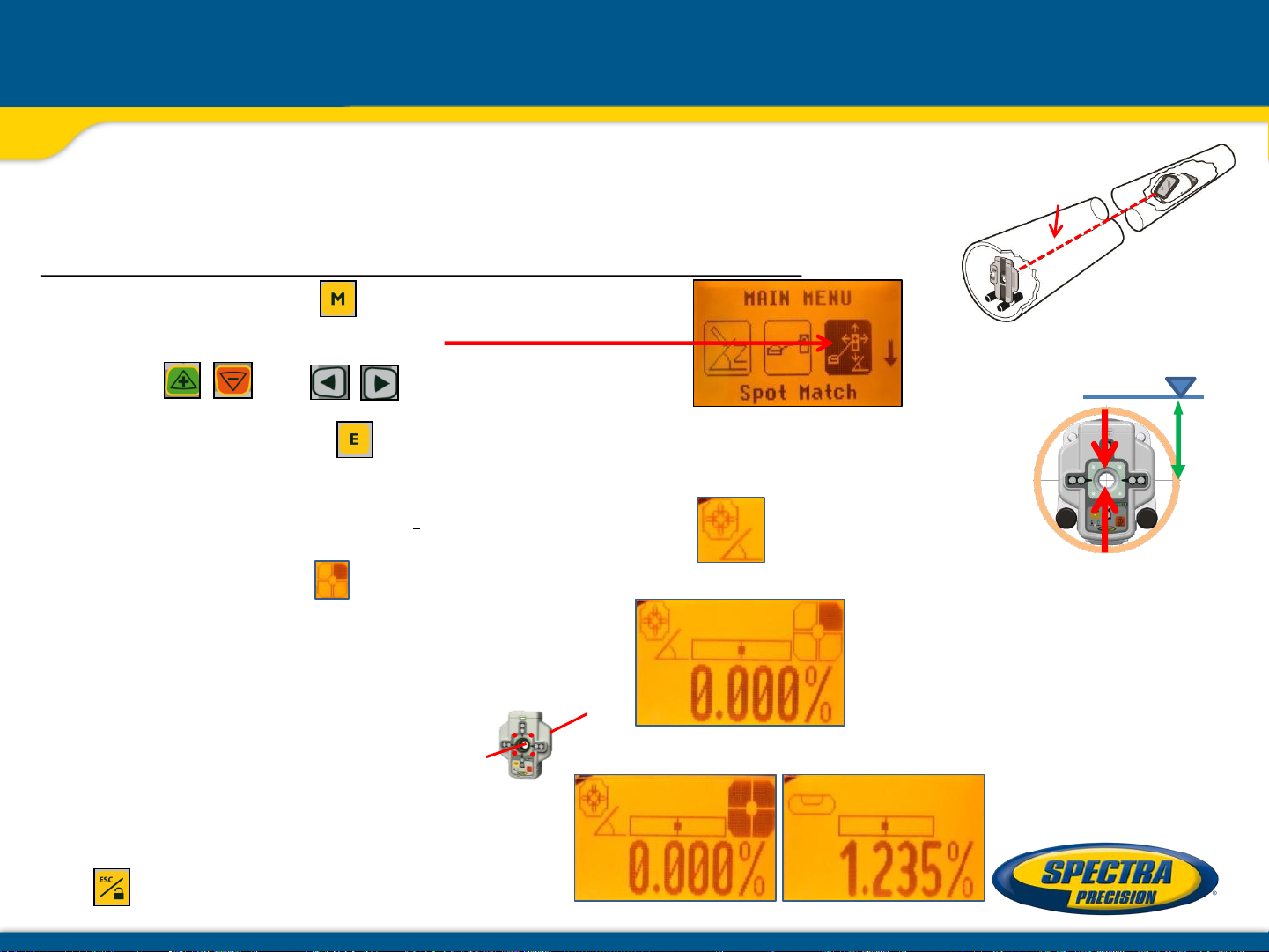
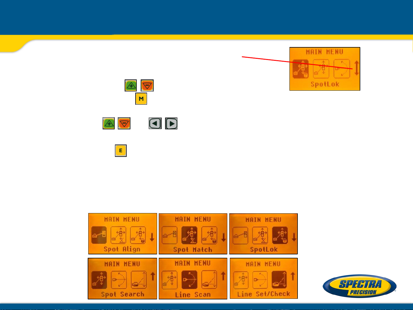
Menu functions – Spot Match (only DG813)
Automatic-Spot-Match can be used for measuring an unknown
grade value in an existing pipe or open trench.
Don’t start Spot Match while the Reference Check is running.
Press and release the button at the standard
display and select Spot Match
using the and buttons.
Pressing and releasing button starts the automatic Spot Match while
the beam becomes a rotating fan beam which will be automatically aligned
to the SF803‘s center position.
Note: The left SF symbol along with a grade symbol flashes while an
additional SF symbol at the right site of the display indicates the beam movement until the
beam is centered.
%?
Z%
When Spot Match has finished,
the beam goes through the SF hole and the measured grade value will be displayed.
Automatic Spot Match can be exited
any time by pressing and releasing
the button.
Page 31
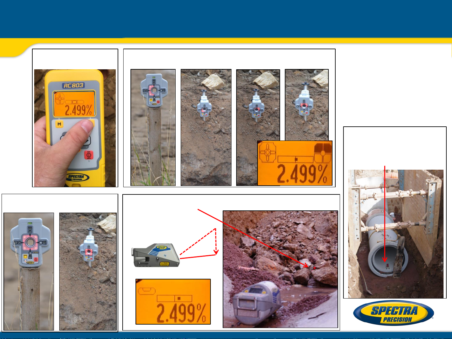
Spot Match at the jobsite
Adjust the Spot Finder‘s center hole to the center of the laser beam
then set up the laser at the manhole or at the first pipe
Automatic Spot Match can be
used to measure the grade value
of an existing pipe which needs
to be replaced but also
to check if the pipes
have laid correctly the day before
%?
Place the Spot Finder at the last pipe
Select Spot Match at
the menu and press E
Page 32

Spot Match at the jobsite
Rotating Fan beam searches for the Spot Finder‘s center;
LEDs indicate the beam movement
All LEDs On confirm Spot Match completed; beam goes through
the SF center hole; display shows the measured grade value
Replace the Spot Finder with the target plate
and proceed laying pipes
Page 33

Menu functions – SpotLok (only DG813)
Automatic SpotLok (like PlaneLok) can be used to align and hold
the beam automatically to the SF803’s center point in automatic
or manual mode. It can also be used in manual mode for establishing an
automatic steep slope reference in mountain areas.
Don’t start SpotLok while the Reference Check is running.
Press and release the button at the standard display and select SpotLok
using the and buttons.
Pressing and releasing button starts automatic SpotLok while the beam
becomes a rotating fan beam which will be automatically aligned to
the SF803‘s center position.
Note: The left SF symbol together with a lock symbol flashes while
an additional SF symbol at the right site of the display indicates
the beam movement until the beam is centered.
Automatic SpotLok complete: LEDs solid for 5 min.,
then flashing every 5 seconds to confirm SpotLok is OK.
Automatic SpotLok can be exited any
time by pressing and releasing button
where the unit switches back to
automatic or manual mode.
Page 34

Menu functions – Manual Spot Search (only DG813)
Spot Search mode is used for pipe laying by detecting the beam manually using the
Spot Finder SF803 and can be activated in automatic and manual mode.
Using the “Over the Top” application, the Spot Finder detects the fan beam while the remote
control’s display provides the information for positioning the pipe correctly at the required
direction and elevation.
Press and release the button at the standard display and select Spot Search
using the and buttons.
Pressing and releasing button starts the manual Spot Search mode while the
beam becomes a rotating fan beam.
The empty SF symbol indicates the Spot Search mode has been activated.
A black block at the SF symbol indicates the beam position at the Spot Finder and gives the
direction for finding the center of the beam. Two black blocks on top or the bottom of the
SF symbol confirm the correct direction.
4 black blocks at the SF symbol confirm the Spot Finder has been adjusted to the center of
the beam which means the pipe has been placed correctly.
Manual Spot Search can be exited any
time by pressing and releasing button.
Page 35

Menu functions – Line Scan / Line Set Check
Line Scan - For a faster second day setup, line scan enables complete
automatically movement of the laser beam to the left and right limits.
Press and release the button at the standard display and select Line Scan
using the and buttons.
Pressing and releasing button activates the Line Scan mode while the laser
beam moves horizontally to the right/left limits and stops at the center position.
When the beam crosses the target press the button to stop the automatic
beam movement.
Corrections for centering the beam at the target’s bulls-eye can be done using
the buttons.
Line Set/Check - Moves the laser beam vertically to its maximum limit
for setting line in a first day setup without a SF803.
Press and release the button and select Line Set/Check
using the and buttons.
Pressing and releasing button activates the Line Set/Check mode.
The beam moves to the 0% position while the flashing Line Set/Check symbol
appears together with a bubble vial.
Page 36

Menu functions – Line Set Check (cont.)
Roll the unit at the invert or use the screws of the invert plate until the vial is
centered and the Line Set/Check symbol stops flashing.
Pressing and releasing the button again starts the beam moving vertical
automatically up to 45°/ 100%.
Using the or button at the RC803 remote control or at the laser stops the
automatic upwards beam movement.
Adjust the beam using buttons until the beam is centered at the line stake.
After aligning the beam to the required direction position, pressing and releasing
the button starts the beam plumb down movement to the previous dialed in
grade value.
Page 37

Menu functions – Reference Check / Standby mode
Start Reference Check – Before starting some sensitive pipe work, an
additional Reference Check can be started manually.
Press and release the button at the standard display and select Reference
Check
using the and buttons.
Pressing and releasing button starts the Reference Check considering the
current temperature inside the housing. While the unit checks the correct 0%
reference the beam flashes once a second simultaneously with a
thermometer symbol at the display.
Standby Mode – activating/deactivating the Standby Mode.
Press and release the button at the standard display and select Standby
using the and buttons.
Pressing and releasing button activates the Standby mode.
The self-leveling will be stopped and the beam will be turned off while the
Line alert is still active. The display shows the Standby symbol.
To deactivate Standby mode and restore full operation of the laser,
press and release button again.
Page 38

Menu functions – Info
Info - The DG/RC information (software version, ID, etc.), runtime of the DG
or the actual used radio channel will be displayed.
Press and release the button at the standard display and select Info
using the and buttons.
Pressing and releasing button opens the Info’s submenu.
The buttons can be used to toggle between
About Laser, Runtime and Radio.
Press and release to show the Laser Info (Serial number, Software
version, internal temperature), Runtime (endless counter) or Radio (actual
radio channel) information
Page 39

Menu functions – Service / Entering Setting Details
Service – capability to recalibrate the level sensors.
Press and release the button at the standard display and select Service
using the and buttons.
Pressing and releasing button starts the Z-axis calibration process at 0%.
The Service submenu also offers access to special features for technicians only.
Setting Menu Details – offers the different setting features.
Press and release the button at the standard display and select Settings
using the and buttons.
Pressing and releasing button opens the Setting’s menu.
and buttons can be used to select the desired Setting
function then press button to open the selected submenu.
Page 40
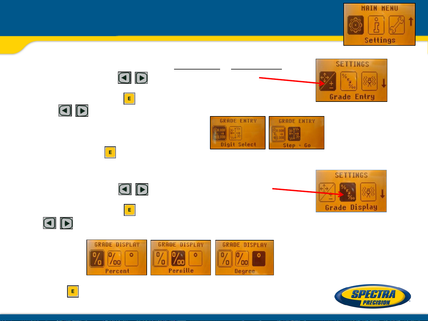
Settings – Grade Entry / Grade Display
Grade Entry – offers selection of Step + Go or Digit Select Mode.
Press and release the buttons until Grade Entry
is displayed.
Pressing and releasing button opens the submenu.
Use the buttons to toggle between Step + Go and Digits Select. (Default).
Press and release to confirm the selection.
Grade Display – offers the different Grade Display options.
Press and release the buttons until Grade Display
will appear.
Pressing and releasing button opens the submenu.
The buttons can be used to toggle between
Percent, (Default) Per Mille Degree.
Press the button to confirm the selection.
Page 41

Settings – Sensitivity / Line Alert
Sensitivity Selection – offers three different sensitivity options.
Press and release buttons until Sensitivity is displayed.
Pressing and releasing button opens the submenu.
Use the buttons to toggle between Low, Mid (Default) and High.
Press the button to confirm the selection.
Line Alert– offers three different Line Alert options.
Press and release and buttons until Line Alert is displayed.
Pressing and releasing button opens the submenu.
Use the buttons to toggle between LA 5 min (Default), LA 30 sec and LA Off.
Press the button to confirm the selection.
Page 42

Settings – User Name / Set Password
User Name – offers the activation of the user name.
Press and release and buttons until User Name is displayed.
Pressing and releasing button opens the submenu; cursor flashes.
Use the button to toggle between both lines.
Pressing and releasing button moves the cursor to the right/left.
Press and release buttons to change the character (letters and
numbers).
If the button will be hold for a longer time, the speed of changing the
characters is increasing.
Press the button to store the user name.
Set Password – a password can be entered.
Press and release and buttons until Set Password is displayed.
Pressing and releasing button opens the submenu.
Use button 1 to 6 to type in a password at the second row containing
of 4 digits and repeat the password at the third row.
A previous used password needs to be typed in at the row “Old”.
Press and release button to store the selected password; unit falls
back to the standard display.
Page 43

Settings – Password On/Off / RF Channel
Password ON/OFF – activating/deactivating Password function.
Press and release and buttons until Password On/Off
is displayed.
Pressing and releasing button opens the submenu.
Use the buttons to toggle between Password On and Password Off.
Press the button to confirm the selection.
Any time when the DG will be turned on, the password has to be entered after the password
function has been confirmed.
Typing in a wrong password turns off the DG immediately.
Radio RF Channel – offers the selection of a different radio channel.
Press and release and buttons at the laser until RF Channel
is displayed.
Pressing and releasing button opens the submenu.
Use the and buttons to toggle between RF Channel k=1 and Channel k=6
Press the button to confirm the channel.
After changing the radio channel,
the RC803 and SF803 need to be
paired again.
Page 44

Settings – Language / Position Info
Select Language – offers language selection for the main menu text.
Press and release and buttons until Language is displayed.
Pressing and releasing button opens the submenu.
Use the and buttons to toggle between the different language
options.
Press the button to confirm the selection.
Position Info – capability of changing transmitters geographical location
Press and release and buttons until Position Info
is displayed.
Pressing and releasing button opens the submenu; the cursor flashes.
Pressing and releasing button moves the cursor to the right/left.
Use the button to toggle between Latitude and Altitude.
Use the buttons for editing the required numbers, then press
the button to confirm the dialed in numbers.
Page 45

Error
codes
Description
Solution
21
Temporary EEprom problem
Repeat pairing and re-enter the customer
settings
120
LA
changed
Check laser beam
130
Mechanical Limit during
-
o
Re
point; check if existing slope is
below/above
140
Laser beam blocked
nly at DG813
Make sure there are no obstacles
between the transmitter and the
141
Time Out
self
in the allowed
Check radio operating range/ connection;
ensure a stable
Troubleshooting DG813/DG613
Any error message can be deleted with a short press of the button.
The table shows the related description and possible solutions.
The next service center should be contacted if a different error message as shown at the
table will be displayed.
alert - Unit setup has been
Spot Match
nly at DG813
- o
– Automatic alignment or
-leveling could not be completed
time
elevation/direction
-align the closer to the alignment
-12% to +40%
SF803
laser setup
Page 46

Laser setup - Existing accessories
– DG613/DG813 fit into a 6 inch/150 mm pipe
– 1238 1248
– 1230/1237 heavy duty invert plate
10 inch
250 mm
– 1239 vertical pole
8 inch
200 mm
12 inch
300 mm
15 inch
400 mm
Page 47

Laser Setup using 1230/1239
After mounting the pipe laser
to the pole, dial in 0% and
measure the distance from the
invert to the beam’s center
Place the 936 target in front
and adjust the bulls-eye to the
beam – disregard the scale
but check the bubble vial
when laying the pipes.
Page 48

Laser Setup using T-bar/1239
T - bar with 1239 fixed pole for big pipes
Speed release
handle
Vertical
centerline
Vertical
pole
T-bar
T-bar
section
 Loading...