

Page 1

ADLCONF SoŌ ware
User Guide
Page 2

Contact Information
Customer support and sales contacts
Quality, technology, and service are the hallmarks of Paci c Crest. We
provide easy access to our customer service department to keep you
running e ciently.
Headquarters EMEA Offi ce
Paci c Crest HAL Trade Center
510 DeGuigne Drive Bevelandseweg 150
Sunnyvale, CA 94085 1703 AX Heerhugowaard
U.S .A e Netherlands
Tel: 1-800-795-1001 (U.S.A toll free) Tel: +31-725-724-408
(408) 481-8070 (outside the U.S.A) Fax: +31-725-348-288
Fax: (408) 481-8984
Sales email:
Support email: support@Paci cCrest.com
Repair info: pccservice@Paci cCrest.com
Web: www.Paci cCrest.com
Support hours are 8 am to 5 pm Paci c Time. Please visit our website for
up-to-date news and product announcements. Firmware and software
upgrades are available from our website, usually free of charge.
Legal notices
©2012 Paci c Crest. All rights reserved. Adaptation, or translation of
this manual is prohibited without prior written permission of Paci c
Crest, except as allowed under the copyright laws. is document
contains proprietary information that is protected by copyright. All
rights reserved. e information contained in this document is subject
to change without notice.
Trimble is a trademark of Trimble Navigation Limited, registered in
the United States and in other countries. TRIMMARK and TRIMTALK
are trademarks of Trimble Navigation Limited. SATEL is a registered
trademark of SATEL Oy. Stonex is a registered trademark of Stonex
Europe. Microsoft, Windows, and Windows Vista are either registered
trademarks or trademarks of Microsoft Corporation in the United
States and/or other countries. All trademarks are the property of their
respective owners.
sales@Paci cCrest.com
May 2013 Rev B
ADLCONF User Guide
2
Page 3

Contents
Introduction . . . . . . . . . . . . . . . . . . . . . . . . . . . . . . . . . . . . . . . . . . . . . . . . . . . . . . . . . . . . . . . . . . . 4
Technical Support. . . . . . . . . . . . . . . . . . . . . . . . . . . . . . . . . . . . . . . . . . . . . . . . . . . . . . . . . . . . . . . . . . . . . . . . . . . . . . . . . . . . . . . . 4
Your Comments. . . . . . . . . . . . . . . . . . . . . . . . . . . . . . . . . . . . . . . . . . . . . . . . . . . . . . . . . . . . . . . . . . . . . . . . . . . . . . . . . . . . . . . . . . 4
Installing the Software . . . . . . . . . . . . . . . . . . . . . . . . . . . . . . . . . . . . . . . . . . . . . . . . . . . . . . . . . . 5
Running the Software . . . . . . . . . . . . . . . . . . . . . . . . . . . . . . . . . . . . . . . . . . . . . . . . . . . . . . . . . . . 5
ADLCONF Menus . . . . . . . . . . . . . . . . . . . . . . . . . . . . . . . . . . . . . . . . . . . . . . . . . . . . . . . . . . . . . . . 6
File menu . . . . . . . . . . . . . . . . . . . . . . . . . . . . . . . . . . . . . . . . . . . . . . . . . . . . . . . . . . . . . . . . . . . . . . . . . . . . . . . . . . . . . . . . . . . . . . . . 6
Edit menu. . . . . . . . . . . . . . . . . . . . . . . . . . . . . . . . . . . . . . . . . . . . . . . . . . . . . . . . . . . . . . . . . . . . . . . . . . . . . . . . . . . . . . . . . . . . . . . . 7
Help menu . . . . . . . . . . . . . . . . . . . . . . . . . . . . . . . . . . . . . . . . . . . . . . . . . . . . . . . . . . . . . . . . . . . . . . . . . . . . . . . . . . . . . . . . . . . . . . . 8
Connecting to the Radio . . . . . . . . . . . . . . . . . . . . . . . . . . . . . . . . . . . . . . . . . . . . . . . . . . . . . . . . . 9
Demo mode. . . . . . . . . . . . . . . . . . . . . . . . . . . . . . . . . . . . . . . . . . . . . . . . . . . . . . . . . . . . . . . . . . . . . . . . . . . . . . . . . . . . . . . . . . . . .11
Identifi cation Tab . . . . . . . . . . . . . . . . . . . . . . . . . . . . . . . . . . . . . . . . . . . . . . . . . . . . . . . . . . . . . . 12
Radio Link Tab . . . . . . . . . . . . . . . . . . . . . . . . . . . . . . . . . . . . . . . . . . . . . . . . . . . . . . . . . . . . . . . . 13
Current Channel . . . . . . . . . . . . . . . . . . . . . . . . . . . . . . . . . . . . . . . . . . . . . . . . . . . . . . . . . . . . . . . . . . . . . . . . . . . . . . . . . . . . . . . . 14
Import Channels . . . . . . . . . . . . . . . . . . . . . . . . . . . . . . . . . . . . . . . . . . . . . . . . . . . . . . . . . . . . . . . . . . . . . . . . . . . . . . . . . . . . . . . .14
Scan Mode . . . . . . . . . . . . . . . . . . . . . . . . . . . . . . . . . . . . . . . . . . . . . . . . . . . . . . . . . . . . . . . . . . . . . . . . . . . . . . . . . . . . . . . . . . . . . .14
Link Rate . . . . . . . . . . . . . . . . . . . . . . . . . . . . . . . . . . . . . . . . . . . . . . . . . . . . . . . . . . . . . . . . . . . . . . . . . . . . . . . . . . . . . . . . . . . . . . .15
Modulation Type. . . . . . . . . . . . . . . . . . . . . . . . . . . . . . . . . . . . . . . . . . . . . . . . . . . . . . . . . . . . . . . . . . . . . . . . . . . . . . . . . . . . . . . .15
Sensitivity. . . . . . . . . . . . . . . . . . . . . . . . . . . . . . . . . . . . . . . . . . . . . . . . . . . . . . . . . . . . . . . . . . . . . . . . . . . . . . . . . . . . . . . . . . . . . . . 16
TX Power Level . . . . . . . . . . . . . . . . . . . . . . . . . . . . . . . . . . . . . . . . . . . . . . . . . . . . . . . . . . . . . . . . . . . . . . . . . . . . . . . . . . . . . . . . .17
Address Settings . . . . . . . . . . . . . . . . . . . . . . . . . . . . . . . . . . . . . . . . . . . . . . . . . . . . . . . . . . . . . . . . . . . . . . . . . . . . . . . . . . . . . . . .17
Transmit Settings . . . . . . . . . . . . . . . . . . . . . . . . . . . . . . . . . . . . . . . . . . . . . . . . . . . . . . . . . . . . . . . . . . . . . . . . . . . . . . . . . . . . . . . 18
CSMA. . . . . . . . . . . . . . . . . . . . . . . . . . . . . . . . . . . . . . . . . . . . . . . . . . . . . . . . . . . . . . . . . . . . . . . . . . . . . . . . . . . . . . . . . . . . . . . . . . . 20
Use Forward Error Correction . . . . . . . . . . . . . . . . . . . . . . . . . . . . . . . . . . . . . . . . . . . . . . . . . . . . . . . . . . . . . . . . . . . . . . . . . . .20
Advanced settings. . . . . . . . . . . . . . . . . . . . . . . . . . . . . . . . . . . . . . . . . . . . . . . . . . . . . . . . . . . . . . . . . . . . . . . . . . . . . . . . . . . . . . . 20
Disable TX . . . . . . . . . . . . . . . . . . . . . . . . . . . . . . . . . . . . . . . . . . . . . . . . . . . . . . . . . . . . . . . . . . . . . . . . . . . . . . . . . . . . . . . . . . 20
Scramble Control . . . . . . . . . . . . . . . . . . . . . . . . . . . . . . . . . . . . . . . . . . . . . . . . . . . . . . . . . . . . . . . . . . . . . . . . . . . . . . . . . . .21
Automatic turn o . . . . . . . . . . . . . . . . . . . . . . . . . . . . . . . . . . . . . . . . . . . . . . . . . . . . . . . . . . . . . . . . . . . . . . . . . . . . . . . . . . 21
RX LED de nition . . . . . . . . . . . . . . . . . . . . . . . . . . . . . . . . . . . . . . . . . . . . . . . . . . . . . . . . . . . . . . . . . . . . . . . . . . . . . . . . . . .21
Insert source address. . . . . . . . . . . . . . . . . . . . . . . . . . . . . . . . . . . . . . . . . . . . . . . . . . . . . . . . . . . . . . . . . . . . . . . . . . . . . . . . 22
Disable Antenna Detection . . . . . . . . . . . . . . . . . . . . . . . . . . . . . . . . . . . . . . . . . . . . . . . . . . . . . . . . . . . . . . . . . . . . . . . . . .22
Serial Interface Tab. . . . . . . . . . . . . . . . . . . . . . . . . . . . . . . . . . . . . . . . . . . . . . . . . . . . . . . . . . . . . 23
Port. . . . . . . . . . . . . . . . . . . . . . . . . . . . . . . . . . . . . . . . . . . . . . . . . . . . . . . . . . . . . . . . . . . . . . . . . . . . . . . . . . . . . . . . . . . . . . . . . . . . .24
Baud Rate. . . . . . . . . . . . . . . . . . . . . . . . . . . . . . . . . . . . . . . . . . . . . . . . . . . . . . . . . . . . . . . . . . . . . . . . . . . . . . . . . . . . . . . . . . . 24
Protocol . . . . . . . . . . . . . . . . . . . . . . . . . . . . . . . . . . . . . . . . . . . . . . . . . . . . . . . . . . . . . . . . . . . . . . . . . . . . . . . . . . . . . . . . . . . . . . . .24
Protocol Type . . . . . . . . . . . . . . . . . . . . . . . . . . . . . . . . . . . . . . . . . . . . . . . . . . . . . . . . . . . . . . . . . . . . . . . . . . . . . . . . . . . . . . .24
Data Security. . . . . . . . . . . . . . . . . . . . . . . . . . . . . . . . . . . . . . . . . . . . . . . . . . . . . . . . . . . . . . . . . . . . . . . . . . . . . . . . . . . . . . . .25
Advanced settings. . . . . . . . . . . . . . . . . . . . . . . . . . . . . . . . . . . . . . . . . . . . . . . . . . . . . . . . . . . . . . . . . . . . . . . . . . . . . . . . . . . . . . . 26
Soft Break Disabled. . . . . . . . . . . . . . . . . . . . . . . . . . . . . . . . . . . . . . . . . . . . . . . . . . . . . . . . . . . . . . . . . . . . . . . . . . . . . . . . . .26
Break to Command. . . . . . . . . . . . . . . . . . . . . . . . . . . . . . . . . . . . . . . . . . . . . . . . . . . . . . . . . . . . . . . . . . . . . . . . . . . . . . . . . .26
Turn o radio LCD backlight after 20 seconds. . . . . . . . . . . . . . . . . . . . . . . . . . . . . . . . . . . . . . . . . . . . . . . . . . . . . . . . 26
Enable/Disable Radio Con guration via radio interface . . . . . . . . . . . . . . . . . . . . . . . . . . . . . . . . . . . . . . . . . . . . . .26
Frequencies Tab . . . . . . . . . . . . . . . . . . . . . . . . . . . . . . . . . . . . . . . . . . . . . . . . . . . . . . . . . . . . . . . 27
Importing a channel table . . . . . . . . . . . . . . . . . . . . . . . . . . . . . . . . . . . . . . . . . . . . . . . . . . . . . . . . . . . . . . . . . . . . . . . . . . . . . . . 28
Exporting a channel table . . . . . . . . . . . . . . . . . . . . . . . . . . . . . . . . . . . . . . . . . . . . . . . . . . . . . . . . . . . . . . . . . . . . . . . . . . . . . . . 28
Region Codes . . . . . . . . . . . . . . . . . . . . . . . . . . . . . . . . . . . . . . . . . . . . . . . . . . . . . . . . . . . . . . . . . . . . . . . . . . . . . . . . . . . . . . . . . . .28
Programming the radio . . . . . . . . . . . . . . . . . . . . . . . . . . . . . . . . . . . . . . . . . . . . . . . . . . . . . . . . . 29
High Heat Con gurations . . . . . . . . . . . . . . . . . . . . . . . . . . . . . . . . . . . . . . . . . . . . . . . . . . . . . . . . . . . . . . . . . . . . . . . . . . . . . . . 30
Supported combinations of radio settings. . . . . . . . . . . . . . . . . . . . . . . . . . . . . . . . . . . . . . . . . . . . . . . . . . . . . . . . . . . . . . . .31
12.5 kHz Channel Bandwidth . . . . . . . . . . . . . . . . . . . . . . . . . . . . . . . . . . . . . . . . . . . . . . . . . . . . . . . . . . . . . . . . . . . . . . . .32
25 kHz Channel Bandwidth. . . . . . . . . . . . . . . . . . . . . . . . . . . . . . . . . . . . . . . . . . . . . . . . . . . . . . . . . . . . . . . . . . . . . . . . . .32
US Narrowbanding Regulations . . . . . . . . . . . . . . . . . . . . . . . . . . . . . . . . . . . . . . . . . . . . . . . . . . . . . . . . . . . . . . . . . . . . . . . . .32
Restoring Factory Settings. . . . . . . . . . . . . . . . . . . . . . . . . . . . . . . . . . . . . . . . . . . . . . . . . . . . . . . 34
Undoing Changes to Radio Settings. . . . . . . . . . . . . . . . . . . . . . . . . . . . . . . . . . . . . . . . . . . . . . . 34
Printing Radio Settings . . . . . . . . . . . . . . . . . . . . . . . . . . . . . . . . . . . . . . . . . . . . . . . . . . . . . . . . . 35
Closing the ADLCONF Program . . . . . . . . . . . . . . . . . . . . . . . . . . . . . . . . . . . . . . . . . . . . . . . . . . . 35
ADLCONF User Guide
3
Page 4

Introduction
ADLCONF is a suite of software utilities for configuring and troubleshooting the Pacific
Crest Advanced Data Link (ADL) line of digital communication radios and modems. It
ships with all radio modems in the ADL family and is available for free download from
the Pacific Crest website (
computer attached using a serial cable to an ADL radio enables you to check the status of
the radio, enter channel tables, and set radio parameters such as channel bandwidth and
output power.
Technical Support
If you have a problem and cannot find the information you need in the product
documentation, contact your local dealer or go to the Support area of the Pacific Crest
website (www.pacificcrest.com/support.php). Product updates, documentation, and any
support issues are available for download.
www.pacificcrest.com). Running the ADLCONF software on a
If you need to contact technical support, email
Your Comments
Your feedback about the supporting documentation helps us to improve it with each
revision. Email your comments to info@pacificcrest.com.
support@pacificcrest.com.
ADLCONF User Guide
4
Page 5

Installing the Software
1. Download the latest version of ADLCONF software from www.pacificcrest.com/
support.php?page=updates
2. Extract the contents of the zip file.
3. Some firewalls prevent the download of executable files, so the software installer is
named ADLCONF_setup.xxx. Right-click the file, select the Rename option and then
change the “xxx” to “exe”.
4. Double-click the installer file to install the ADLCONF software.
, and save it to a folder on your compute.
Running the Software
Do one of the following:
• Double-click the ADLCONF icon on the computer desktop.
• Click Start / All Programs / Pacific Crest / ADLCONF / ADLCONF.
• Click Start / Run, enter C:\Program Files\Pacific Crest\ADLCONF\ADLCONF.
exe and then click
If you have problems running the ADLCONF software on Windows® 7 or a 64-bit computer
with the Windows Vista® operating system, do the following:
OK.
1. Close the software.
2. Double-click My Computer or start Windows® Explorer.
3. Navigate to C:/Program Files/Pacific Crest/ADLCONF/ and then right-click
ADLCONF.exe.
4. Click
5. In the Compatibility tab, click
6. Select Windows XP, Vista 32, or Windows 7 and then click
7. Restart the ADLCONF software.
Properties.
Run this program in compatibility mode for.
OK.
ADLCONF User Guide
5
Page 6
ADLCONF Menus
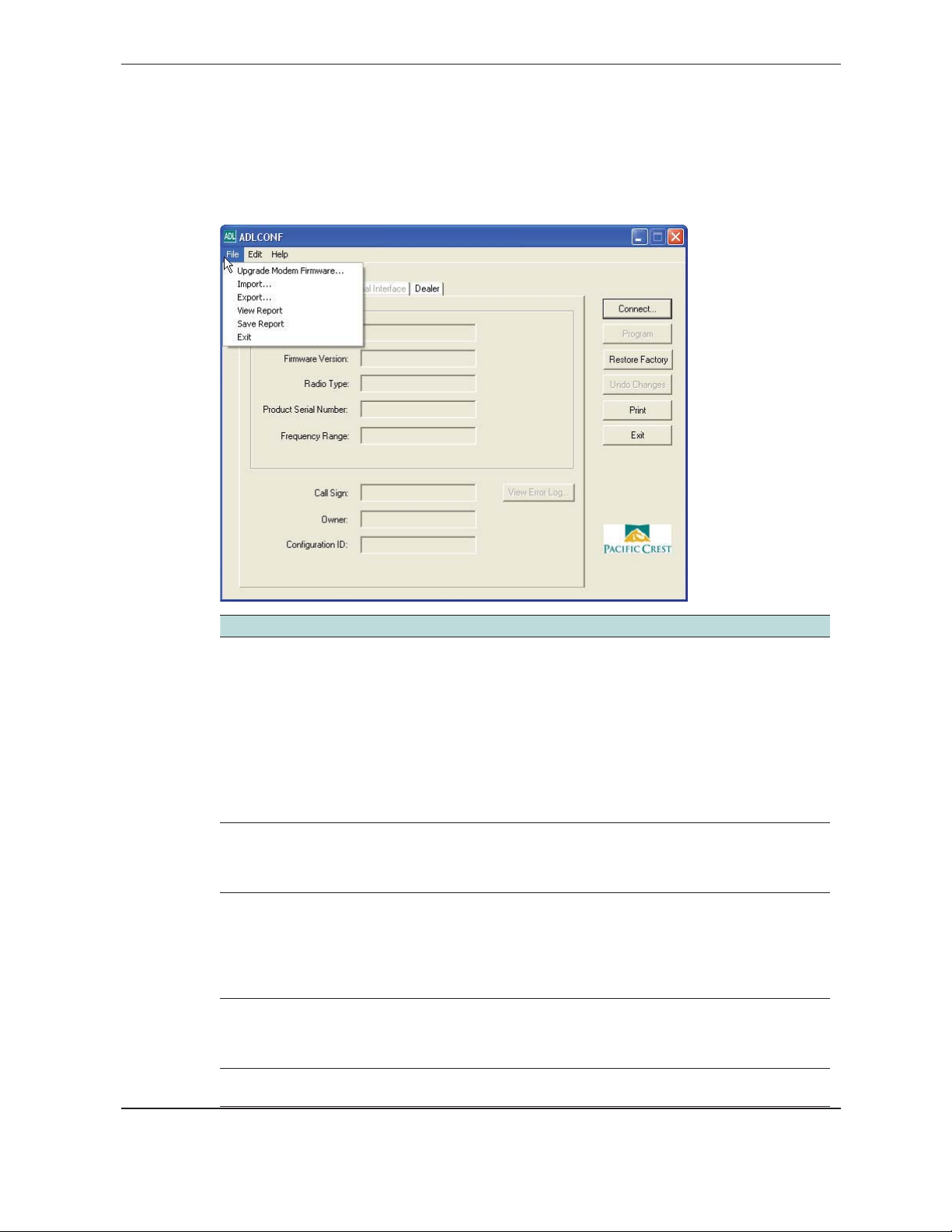
The main ADLCONF dialog contains three main menus: File, Edit, and Help.
File menu
Select… to…
Upgrade Modem
Firmware
Import import radio configuration files (*.dat) from your computer to the ADLCONF
Export save the radio configuration (*.dat) to your computer. This enables you to
View Report view on a web browser all the configuration parameters of the attached
Save Report save a *.txt copy of the configuration report to any location accessible to
ADLCONF User Guide
select a firmware file (*.bin format) to upload into the attached ADL
radio modem. Pacific Crest recommends that you save the radio’s current
configuration to your computer before upgrading firmware. Use the Export
option described below to save the configuration. Before upgrading the
firmware, the software prompts you to connect or reconnect to the radio.
Connecting to the Radio, page 9.
See
Note: if you wish to upgrade the firmware of an ADL radio module
embedded within another product, that product may restrict you to using
only one baud rate. If so, you must select a special version of firmware made
especially for your product. Please check with your dealer, your product’s
manufacturer or the Pacific Crest web site to obtain this special firmware.
software. These files contain the radio parameters displayed and edited
on the Radio Link and Serial Interface screens. Click Program to upload the
configuration to the attached radio.
create one configuration and copy it to multiple radios.
Note – When you export a configuration you only create a *.dat file. To
configure a radio, you must view a configuration in the software (either by
creating it or by importing an existing configuration) and then click Program
.
radio. In addition, this HTML-formatted report shows firmware settings that
may help Pacific Crest support technicians to diagnose problems if the radio
requires service.
your computer.
6
Page 7
Select… to…
Exit exit the software.
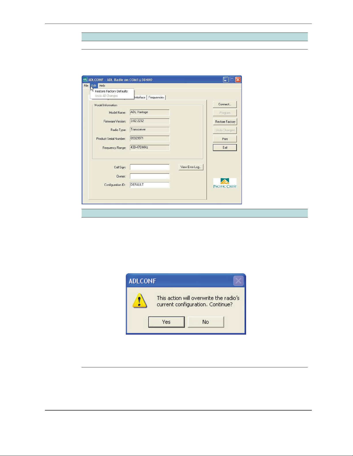
Edit menu
Select… to…
Restore Factory
Defaults
view the radio factory defaults.
Different ADL radio products use different default configuration parameters.
Regardless of how you reconfigure an ADL radio, it always remembers the
original default settings. To view the defaults in the software, select Edit /
Restore Factory Defaults or click
The software must first connect (or reconnect) to the radio. For more
information, see
If the software already shows a radio configuration, a message appears.
Click Yes to copy the default settings from the radio’s permanent memory to
the computer RAM for review and editing. The radio does not use any changes
until you click
restoring factory defaults, the ADLCONF current channel table is retained.
Restore Factory.
Connecting to the Radio, page 9.
Program in the main dialog or in the Exit dialog. When
ADLCONF User Guide
7
Page 8
Select… to…
Undo All
Changes
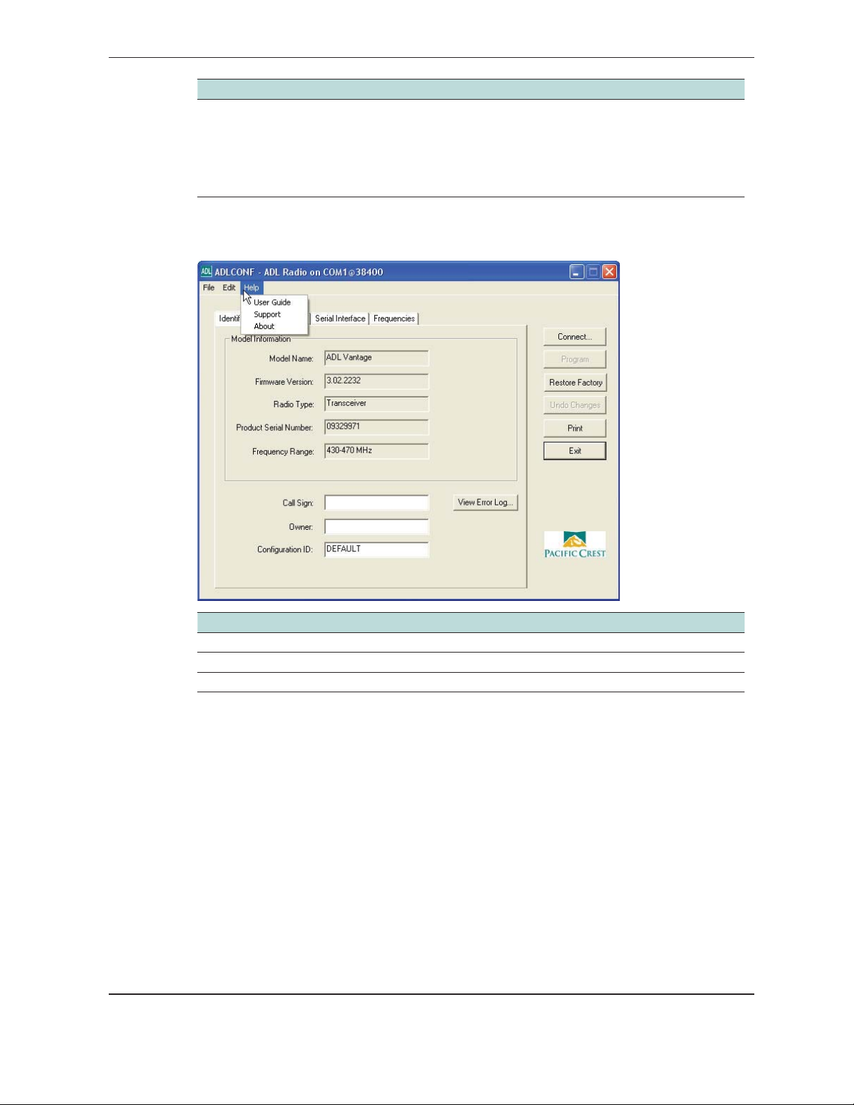
Help menu
discard all the configuration changes you made during this session.
Settings on all the ADLCONF screens are reset to what was in effect when you
started this session. Selecting Undo All Changes does not affect any settings
in the radio or any configuration file on your computer. To change the
radio configuration, you must make changes in the software and then click
Program.
Select… to…
User Guide view a copy of the ADLCONF User Guide (this document).
Support access links to Pacific Crest
About view which version of the software is installed on your computer.
ADLCONF User Guide
Technical Support and the Pacific Crest website.
8
Page 9
Connecting to the Radio
To connect the software to an ADL radio:
1. Start the software.
2. Use the provided programming cable to connect the radio to the computer serial port.
If your computer does not have a serial port, connect the programming cable to a
serial-to-USB adaptor cable such as an IOGEAR® Model GUC232A or an FTDI Model
UC232R.
The ADLCONF software program communicates only with Pacific Crest ADL radios.
You must use XDLCONF software to communicate with XDL radios, the PDLCONF
program to communicate with PDL radios and RFMCONF software to communication
with RFM radios. All of these programs are available for free download from www.
PacificCrest.com.
The radio turns on when it is connected to power:
3. Click the Connect button on the right of the main ADLCONF screen.
Note – When the ADLCONF software connects to a radio, it copies the radio settings to the
computer’s memory and overwrites any other settings that may be currently displayed.
If you had made any edits to the copy of the file in the computer memory and then click
Connect, the ADLCONF software does not ask you if you want to save the settings from
the memory to a file on your hard drive.
ADLCONF User Guide
9
Page 10
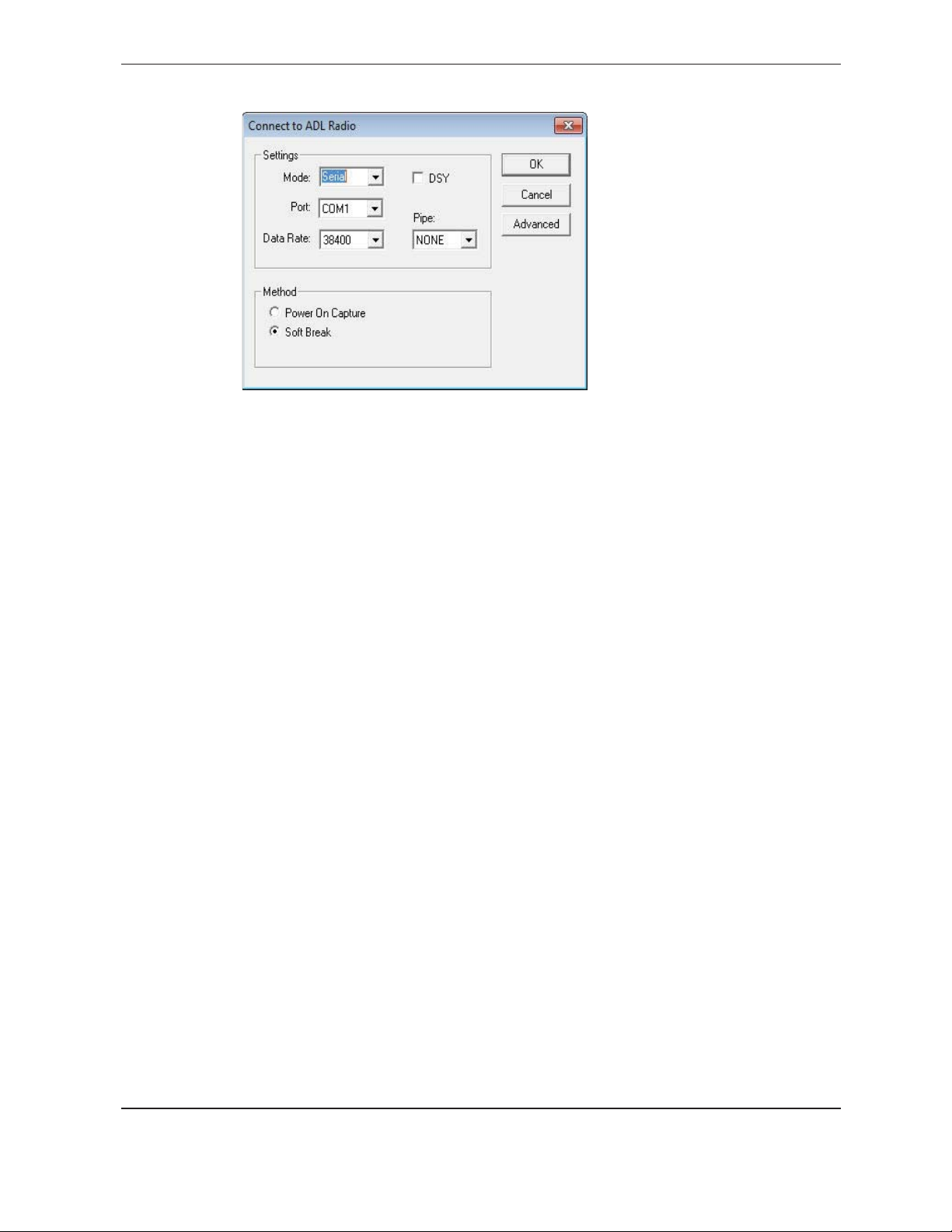
The following dialog appears:
4. To connect to an ADL radio that is connected to the PC via a serial cable, select Serial
in the Mode box. Then select the COM port that the radio is connected to ( from the
Port list) and then select a baud rate ( from the Data Rate list).
5. To connect to an ADL radio that is connected to the PC via the Internet, select TCP in
the Mode box and type in the IP address of the radio.
6. To connect to an ADL radio embedded in an Ashtech GNSS receiver, check the DSY
box and select the number of pipes.
7. When done, click OK on the Connect to ADL Radio window and click
Yes to
overwrite the current configuration.
8. To establish a connection, select one of the following;
– Power On Capture. Turn off the radio. Select the Power On Capture option and then
click
OK. Within 10 seconds, turn on the radio.
The radio accepts a packet switch command (at the selected baud rate) that puts
the radio into command mode.
– Soft Break (the default method). Ensure that the radio has been turned on for at
least four seconds and then click
OK.
This sends a soft break, (ASCII string “+++”) to the radio at the selected baud rate,
which puts the radio into a mode to accept commands from the ADLCONF software
(“command mode”).
Note – If the ADL radio was previously connected to any external device (for example, a
computer, a GNSS receiver, or a measurement device) while using a data rate other than that
shown, the software detects non-communication at the displayed rate and cycles through the
other rates to establish a connection. Some versions of the Windows operating system, and
some serial communications drivers, can prevent this connection; if communication fails, do
the following:
a. Turn off the radio.
b. Disconnect it from the computer.
c. Reconnect the radio, but do not turn it back on.
ADLCONF User Guide
10
Page 11
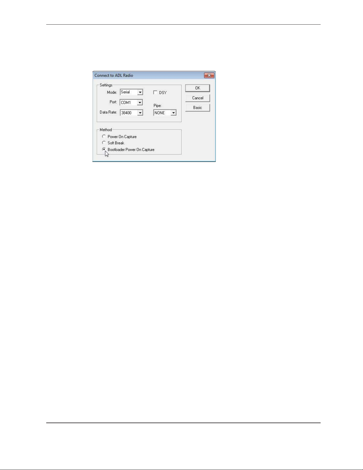
d. Use the Power On Capture method for connection (see above).
If neither of these methods establishes a connection:
1. Turn off the radio and then click
2. Select the Bootloader Power On Capture option and then click OK:
3. Within 10 seconds, turn on the radio. The bootloader firmware puts the radio into
monitor mode that will accept commands.
Demo mode
To simulate connection to an ADL Foundation modem, you can run the software in Demo
mode :
Advanced:
1. Start the software.
2. Press [Alt]+[D] and then click
3. Click
Connect in the main dialog and then follow the steps in Connecting to the
Radio, page 9
.
OK on the Demo Mode dialog.
4. The software uses a pre-set demonstration radio configuration, so you can view the
software features and settings as though you were connected to a radio.
5. You can load an existing radio configuration file (*.dat) to simulate being connected to
that radio; select File / Import. You cannot export configuration files in this mode.
ADLCONF User Guide
11
Page 12

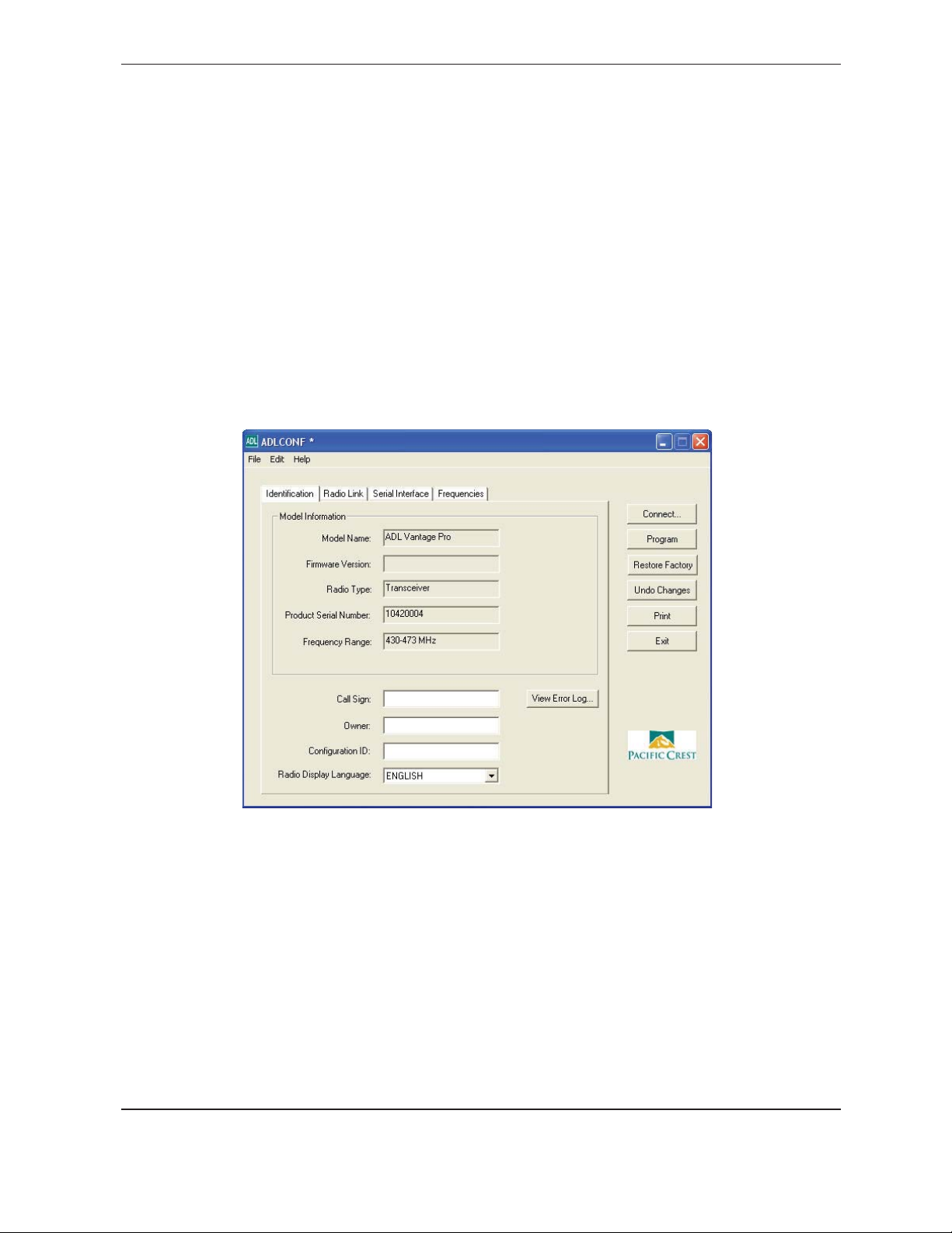
Identification Tab
Connecting to the radio displays the ADLCONF Identification screen :
This screen shows the current configuration of the attached radio:
• Model Name
• Firmware Version
• Radio Type (“Transceiver” or “Receiver Only”)
• Product Serial Number (an 8-digit number where the first two digits are the year
of manufacture, the next two digits are the week of manufacture and the last four
digits are incremented from 0001)
• Frequency Range
You cannot edit these fields.
The Identification screen also enables you to enter a call sign, owner name, and
configuration ID.
For operating in the USA, the FCC requires that radio transmitters periodically broadcast
a station identifier every 15 minutes. The station identifier is the call sign assigned to
USA operators on their station license. The call sign is transmitted in Morse code. It is
not included in any data packet and so is ignored by the receiving radio. However, data
transmission is interrupted for a few seconds while the call sign is being transmitted. If
you leave the call sign field blank, a radio programmed with this configuration file will not
transmit any call sign. If you are operating outside the USA, ask your local authority if you
need to transmit a call sign.
The Configuration ID field is a user-friendly way to identify which configuration has been
loaded into the radio. It can be different from the *.dat filename used when exporting
(saving) the configuration using the File / Export function.
ADLCONF User Guide
12
Page 13

When configuring an ADL Vantage Pro radio, you can select the language that will be
used on the radio’s front panel. The options are English, Chinese, and Russian. When
configuring an ADL Vantage radio, only English is supported.
To save the call sign, owner name, and configuration ID to the radio, click
save any configuration changes to a file on your computer, select File / Export.
ADL radio modems record error logs in the field if the modem experiences a problem. To
view this log, click
View Error Log:
Radio Link Tab
This settings available vary according to the radio protocol selected in the Serial Interface
tab. The following example shows the settings available when the Transparent EOT
protocol is selected:
Program. To
ADLCONF User Guide
13
Page 14

Current Channel
Channel tables are lists of radio settings comprising:
• Channel numbers ( from 1 through 32)
• Frequencies at which the radio receives data on each channel
• Frequencies at which the radio transmits data on each channel (this may be
different from the receive frequencies)
• One channel bandwidth (25 kHz or 12.5 kHz) for all channels in the table
• An optional list of radio serial numbers that can read the channel table
Your dealer should have created a channel table based on your radio license and
loaded it into your ADL radio(s) before delivery. If you did not receive a channel table
with your ADL radio, contact your dealer or Pacific Crest Support.
The radio channel table can contain more than one channel, but the radio can be set to
only one channel at a time. The Current Channel field indicates the current setting. The
list to the right of the field shows all the channels in your channel table. To select another
channel, click it:
Note – The radio is not set to this new channel until you click Program. While all ADL radios
can be reconfigured using the ADLCONF software, some models have user interfaces that
enable you to select other channels on the front of the radio, and others must be reconfigured
using the ADLCONF software.
Import Channels
Click Import Channels to select any other channel table created for your radio by an
authorized Pacific Crest dealer. Channel tables are files with the *.frq file extension.
Other channel table files, such as *.upg files created by the PDLCONF software for
PDL-generation radios, are not compatible with ADL radios.
Note – Government regulations may require you to possess a valid license to transmit data
on certainradio frequencies. This version of the ADLCONFsoftware does notlet you create
channel tables. You must check with your dealer about obtainingfrequency channel tables,
which meet your licensed authorized frequencies or other government regulations.
Scan Mode
Select the MANUAL option when you wish to select the channel manually. Select the
AUTOROVER1 option when you want the radio to automatically scan the entire channel
table and select the one with the strongest decodable signal. The AUTOROVER 1
option will perform one scan when the radio is turned on and will then reset the radio
to MANUAL mode. The AUTOROVER 2 option will perform a scan for the strongest
decodable signal when the radio is turned on and will perform a subsequent scan if the
ADLCONF User Guide
14
Page 15

percentage of received data packets drops under 90%.
Link Rate
This is the rate at which data bits are transmitted or received by the radio modem. The
radio must both receive and transmit at the same rate. The default link rate for all ADL
radios is 9600. You can select a different rate from the list:
Modulation Type
This enables you to configure your radio for either Gaussian Minimum-Shift Keying
(GMSK ) modulation or 4-Level Frequency-Shift Keying (4FSK ) modulation. The default is
GMSK because GMSK is generally less sensitive to interference from environmental noise.
However, 4FSK modulation supports approximately twice the data throughput of GMSK.
When you are using a link rate above 9600, the general recommendation is to use 4FSK
modulation. To switch to 4FSK modulation, select it from the list:
Not all data protocols support 4FSK modulation. If you try to program the radio after
selecting a protocol type on the Serial Interface tab that is incompatible with the selected
modulation type, the following message appears:
ADLCONF User Guide
15
Page 16

For more information, see Supported combinations of radio settings, page 31.
Sensitivity
To optimize your radio for operation in different signal or noise environments, select a
sensitivity level from the list (the PDL radios used the term Digisquelch):
In general, have the Sensitivity level of the radio low enough to reject noise, but high
enough to accept signal. Signal is defined here as the radio energy you want to receive;
noise is defined as everything else. Suitable sensitivity levels to select depending on both
the noise level and the signal level are:
Noise
Signal levels decrease with distance between the transmitter and the receiver. To extend
the range, set Sensitivity to Medium or High, although this can increase the amount of
noise passed through the radio. At times, it may not be easy to determine the noise level
without using a scanner or other RF energy monitor. If you are not sure about the noise
level in your work environment, you can use the following guidelines to set Sensitivity:
Signal
Strong Weak
Loud Low Medium
Quiet Medium High
GNSS Surveying and similar applications Set Sensitivity to
GNSS base station radio Low
GNSS rover radio High
Environmental Monitoring and Similar Applications
Remote sensor radio Low
Local office radio High
Environmental noise levels may change throughout a work day and you may need to
adjust the Sensitivity setting. Most ADL radios include a user interface that enables you to
adjust the Sensitivity in the field without running the ADLCONF software.
ADLCONF User Guide
16
Page 17

TX Power Level
If you purchased an ADL radio as a transceiver, you can configure it for various output
power levels. To adjust the transmit power, select it from the list:
If the radio is a receiver-only, this field is grayed out.
The Radio Type field on the Identification screen (see above) indicates if the radio is a
transceiver or receiver only.
If you are configuring an ADL Vantage Pro radio, this option lets you select four power
levels in addition to a low power setting of 2 Watts. You cannot edit the 2 Watt setting.
The other four settings can be in any order, but not higher than the Max TX Power set by
your dealer.
Select the box above the power level at which the ADL Vantage Pro radio will initially
transmit:
Address Settings
Use these fields to set Local and Destination addresses for any two Pacific Crest ADL
transceivers to communicate exclusively with each other.
The main advantage of addressing is the ability to restrict the usage of transmitted data
to a specified receiver. Any receiving rover radio with a Local address different from the
transmitting base radio’s Destination address will delete the data without repeating it over
the air to other radios or sending it serially to an external device such as a GNSS receiver.
Addressing allows multiple transceiver pairs to operate on the same channel without
“seeing” each other’s data. To do this, the addressed radios need Tx/Rx capability.
The addressing feature only works between two radios. In addition, both radios must be
configured for the Transparent FST/EOT/EOC protocols ( from the Serial Interface tab).
The Local address of one radio must be the same as the Destination address of the other
radio, and vice versa. For example, a radio with Local=X and Destination=Y can only
communicate with another radio with Local=Y and Destination=X.
Note – There is no standard in the radio community that defines addressing. Each
manufacturer does things slightly differently. Therefore, when using radios of different brands
in a communication system, addressing should be turned off on all of them.
To select a Local or Destination address, click the appropriate field and enter a number
between 0 and 254. You can enter only one Local and only one Destination address into
any one radio:
ADLCONF User Guide
17
Page 18

Selecting 255 for the Destination address is a special case designated as broadcast
mode. If you enter 255 as a radio’s Destination address, all Pacific Crest radios sharing the
channel—regardless of their Local address—can receive the data transmissions and either
repeat them over the air to other radios or send them serially to an external device.
The default Local address number is 0 and the default Destination address number is 255.
If you are not using Transparent EOT, Transparent EOC, or Packet Switched protocol, do
not change these defaults.
Note – The Local=0/Destination=255 combination is the only selection that works with
receive-only radios.
Transmit Settings
When configuring the radio with the Transparent EOT/EOC or Packet Switched
protocols, the Transmit Settings section of the Radio Link screen enables you to configure
three aspects of the radio’s transmitter:
• Transmitter Retries
• TX ACK Timeout
• Repeater
Note – Only Transparent EOT/EOC and Packet Switched protocols support transmit retries.
So when you select any other protocol (on the Serial Interface screen described on page 21),
the Transmit Settings section of the Radio Link screen displays only the Repeater check box.
As a general rule, the number of Transmit Retries should be less than the transmission
rate (in seconds) times the link rate (in bits per second) divided by the packet size (in
bits):
For example, if you transmit 3300-bit corrections every second at a 9600 bps radio link
rate, set the Transmit Retries to less than three because it would take more than one
second to transmit 3300 bits three times at 9600 bps, and after one second there will be
newer, more accurate corrections to transmit.
Check the Repeater check box to configure the radio as a repeater, i.e., to automatically
ADLCONF User Guide
(TX Retries) < (Transmission rate) X (Link Rate) ÷ (Packet Size)
18
Page 19

retransmit each data packet it receives. Checking this option displays different fields
depending on the selected protocol. If you selected a non-Trimble protocol and then
check the Repeater check box, the Repeater Delay field appears.
Enter the amount of time you want to elapse between receipt of a data packet and its
retransmission. You may enter any value between 0 and 255.
If you selected the TRIMTALK 450S, TRIMMARK II/IIe, TT450S (HW), or TRIMMARK 3
protocol and then select the Repeater check box, the following repeater modes become
available:
• Select the BASE with One Repeater option to configure the attached radio as a base
station transmitting RTK corrections to one repeater radio
• Select the BASE with Two Repeaters option to configure the attached radio as a base
station transmitting RTK corrections to two repeater radios
• Select the Repeater One option to configure the attached radio as a single repeater
or the first of two repeaters
• Select the Repeater Two option to configure the attached radio as the second of two
repeaters
ADLCONF User Guide
19
Page 20

CSMA
ADL radios are configured in the factory to have the CSMA feature (Carrier Sense Multiple
Access) set to ON. It is illegal to transmit in the United States while CSMA is turned off.
When CSMA is activated, the radio will “listen” on the selected transmission frequency
for any broadcasts. (The selected transmission frequency is indicated in the Radio Link
screen’s Current Channel field.) If no broadcasts are detected, the radio will transmit any
data received on its serial interface. If a radio signal is detected on the selected frequency,
the radio will not transmit but waits 3.3 milliseconds before checking again if it is clear to
transmit. It continues checking until the frequency is clear.
Use Forward Error Correction
Select this check box to place extra bits in the transmitted data, so that other ADL
radios receiving the data can check for transmission errors. Although data throughput is
adversely affected, using forward error correction can greatly improve range; Pacific Crest
strong recommends that you use this feature.
The check box is unavailable (grayed out) if you use Trimble protocols, which do not
support forward error correction. Select the protocol type from the Serial Interface tab.
Advanced settings
Click Advanced to access the following controls:
ADLCONF User Guide
20
Page 21

Disable TX
Select this check box to disable the transmitter when you need to conduct certain tests of
a radio system where you need to ensure that the radio will not transmit. If you select this
check box, remember to clear it or the radio will not transmit data.
Scramble Control
To demodulate a digital transmission, a receiver must synchronize itself with the
transmitter. This can be hard to do when the transmitter sends a long series of one’s or a
long series of zeroes. But if every nth characters in the transmission were switched, a one
to a zero or a zero to a one, and if the receiver was expecting this, it could more easily and
quickly synchronize itself with the transmission. This is essentially what Scramble Control
does and why we recommend you leave it on for all radios.
If you select a protocol type other than Transparent (EOT and EOC) or Packet Switched,
Scrambling Control is automatically disabled although the check box remains selected.
However, if some of the radios in your system are non-Pacific Crest radios, you may need
to turn Scramble Control off.
Note – Trimble protocols require Scramble Control. With a Trimble protocol selected, you are
unable to turn off Scramble Control.
Automatic turn off
The radio turns off automatically when the input voltage reaches a user-specified level.
The default is 9 volts.
You can also select a low voltage warning offset. This is the number of volts above the
automatic turn off level at which the radio interface, if it has one, warns you that the radio
battery charge is low. With a radio shut off value of 9 V and a low voltage warning offset
of 1 V, the radio warns you when the battery reaches 10 V. The radio turns off when the
battery reaches 9 V.
If you are configuring an ADL Vantage Pro radio, the Automatic turn off feature is on
and grayed out. Because of the higher transmit power of the ADL Vantage Pro radio, the
battery can be damaged by overdischarge. To prevent this, the radio always warns you of a
low battery condition at 11 V and shuts off when the battery discharges to 10 V.
RX LED definition
If you have a radio with an Rx LED, you can switch the meanings of the LED to one of the
following:
• Signal received (RF energy above squelch level is detected) – the default
• Data packets received
ADLCONF User Guide
21
Page 22

Insert source address
If you check this box, and program the radio with a local address and a destination address,
both addresses will be added to each transmitted data packet.
Disable Antenna Detection
If you are connected to an ADL Vantage Pro you will see a check box for disabling the
antenna detection function, a feature found only in the ADL Vantage Pro. This feature
protects the radio from transmitting at high power without an antenna, with a damaged
cable or with an antenna that is doesn’t support the radio’s transmit frequency (antenna
mismatch). If you disable this feature you must be ensure that you never transmit without
first manually checking the antenna and cable.
ADLCONF User Guide
22
Page 23

Serial Interface Tab
This tab has the following controls:
In this tab, you can configure the serial interface between the radio and external devices
such as a computer running the ADLCONF software, a GNSS receiver, or monitoring
equipment.
The way you set up the radio to communicate to your computer is how it will
communicate to all external devices (unless your radio is a model with a user interface
on its front panel that enables radio configuration in the field). First, determine which
parameters the GNSS receiver or external equipment requires in the field for serial
communications and then enter these same settings in the Serial Interface tab.
Serial communications require a serial port consisting of a software driver running in
conjunction with the operating system and a physical port—usually a DE9 connector. If
your computer, GNSS receiver, or other external device does not have a serial port, you
can use a serial-to-USB adaptor cable to connect the radio serial cable to the external
device.
ADLCONF User Guide
23
Page 24

Port
Baud Rate
The default baud rate between the computer and the radio is 38400. Select other rates
(between 4800 and 115200) from the Baud Rate list:
Protocol
Protocol Type
You must select a protocol—a set of rules governing the order, syntax, and so on—
of the data communicated between the external device and your radio. All radios
communicating with one another must be set to use the same protocol.
Select the required protocol from the Protocol Type list:
• Transparent with EOT Timeout
• Transparent with EOT Character
• Packet Switched
• TRIMTALK™ 450S
• TRIMTALK II/IIE
• TT450S (HW)
• TRIMMARK™ 3
• SATEL
• Transparent FST
• South
• Stonex Type 1
• U-Link
ADLCONF User Guide
24
Page 25

Protocol Description
Transparent There are three types of “Transparent” protocols, in which the data has no
address or frame characters and are thus “transparent.” Radios using transparent
protocols, however, must know when the transmission has ended (known as End
of Transmission or EOT). There are two ways to do this:
• With a length of time during which there is no transmission (EOT Timeout )
• With a special character (EOT Character)
For systems using Pacific Crest radio modems exclusively, the default setting is
Transparent with EOT Timeout. When you select this, enter the time (between
10 and 2560 milliseconds) that signifies the End of Transmission. The default is 50
milliseconds.
If you select Transparent with EOT Character, select the ASCII character you want
your radios to use. The default is the “NUL” ASCII character. To select another
character, select an option from the EOT Character list: NUL, SOU, STX, ETX, EOT,
ENQ, ACK, BEL, BS, HT, LF, VT, FF, CR, SO, SI, DLE, DC1, DC2, DC3, DC4, NAK, SYN,
ETB, CAN, EM, SUB, ESC, FS, GS, RS, US, SP, QWERTY keyboard characters, and so
on.
Transparent FST is a Pacific Crest protocol optimized for long distance, high speed/
volume data communication. It supports only 4FSK modulation.
Note – Not all data protocols support 4FSK modulation. A message appears if you
try to program the radio after selecting a protocol type that is incompatible with
the modulation type you selected on the Radio Link tab:
Packet
Switched
TRIMBLE The ADL radios support the following variations of the Trimble wireless protocol:
SATEL SATEL is a protocol used by SATEL radios. ADL radios are fully compatible with
This protocol is unique in that it is a “command” mode. In all other protocols,
incoming serial port data is formatted into packets and automatically transmitted.
With Packet Switched protocol, external equipment must provide the packet
formatting, scrambling, error correction, and housekeeping functions, and send
commands to the radio to perform the actual transmission and reception of data.
This may be useful in specialized applications where settings, such as channel
selection, must be changed “on-the-fly” and the controlling serial port equipment
can be programmed to perform these functions.
• TRIMTALK 450S
• TRIMMARK II/IIe
• TT450S (HW)
• TRIMMARK 3
Use the ADLCONF software to select the same protocol used on the Trimble radios
in your network. To communicate with radios configured to use any other Trimble
protocol, set your ADL radio to TRIMTALK 450S protocol.
SATEL radios, but only when set to the SATEL protocol. If SATEL does not appear
in the Protocol Type list, select the Radio Link tab and ensure that you have
selected 4FSK in the Modulation Type field. (SATEL protocol supports only 4FSK
modulation.)
Data Security
To send encrypted messages, enter any combination of 8 alpha-numeric characters into
the Data Code field, select the Enable check box and then program the radio. Only Pacific
Crest XDL, ADL or PDL radios programmed with this code can interpret data sent by any
of the radios—and only when configured to use a Pacific Crest protocol. Although each
generation of Pacific Crest radios (XDL, ADL and PDL) must be programmed using the
respective generation of configuration software, the data security feature is the same for
ADLCONF User Guide
25
Page 26

all products and all types of Pacific Crest radios can be set to use the same code.
Note – If you program a radio to use the Data Security feature, it cannot communicate with
any radio that does not use the same code. When you enable this feature for one radio, it is
a good idea to enable it for all the radios you will use in the same communication network.
Pacific Crest radios with button/LCD interfaces can turn the Data Security feature on or off
in the field, but all other Pacific Crest radios must be returned to the office to disable the Data
Security feature using the appropriate configuration software.
Advanced settings
Click Advanced to access the following functions:
Soft Break Disabled
The ADLCONF software normally connects to a radio using a technique called Soft Break
whereby you attach a radio, turn it on and then click Connect. Selecting this check box
enables you to reconnect to the radio without using the Soft Break technique. This is
normally done under the guidance of a service technician to troubleshoot connection
problems.
Break to Command
The Break to Command function configures the radio to accept a hard break signal
that puts the radio into command mode. Clear this check box for the radio to go into
command mode if it detects a hard break.
Turn off radio LCD backlight after 20 seconds
If the attached radio is equipped with an LCD, this check box configures the LCD
backlight to turn off 20 seconds after the last button on the radio interface is clicked. Clear
this check box for the radio to leave its LCD backlight on as long as the radio is turned on.
Enable/Disable Radio Configuration via radio interface
Some radio models include a keypad for configuring the radio in the field. To prevent field
configuration, clear this check box and then click
Program. To re-enable a radio, clear this check box and then program the radio.
OK to return to the main screen. Click
ADLCONF User Guide
26
Page 27

Radios with an LCD display include an Edit Config screen that indicates if
configuring the radio with the keypad is Enabled or Disabled. The current selection
is displayed with an asterisk on the second row of the Edit Config screen. To switch
the selection, press the down arrow to display the other option and click
are now prompted to enter a passcode, which is 369369 for all ADL radios. To enter
this code, press the right arrow to display a 3 on the second row. Then press the
down arrow to display a 6 and the left arrow to display a 9. Press the right, down,
and left buttons a second time in sequence. When you see 369369 displayed on the
second row of the LCD, press
is changed.
Frequencies Tab
This tab has the following controls:
Enter. You
Enter and the keypad’s ability to configure the radio
In the tab you can configure the radio for receive-only channels. When you first
select the Frequencies tab, the current channel table shows the Rx frequency of
Channel 01 in the RX field.
To add a receive-only channel, click on an “unused” channel, select the RX field,
enter the frequency on which you wish to receive data and then click
ADLCONF User Guide
Apply.
27
Page 28

To clear a receive-only channel, select it and then click Clear.
To clear all receive-only channels, click
To move a channel up or down in the channel table, click on the channel you want to
move and then either click the up or down arrow next the channel table, or “drag and
drop” the channel into its new position.
This configures the channel table that is displayed in the ADLCONF software. To
program the attached radio to receive on this frequency, you must click
below). In addition, select File / Export to save any new radio configurations to your
computer.
Importing a channel table
To display a channel table created by the ADLCONF software, click Import and then
select the required .frq file.
Note – Only a dealer can program a radio with a channel table containing transmit
frequencies unless the channel table was tagged with the serial number of the radio. Please
check with your dealer for an Rx/Tx channel table created for your radio’s serial number.
Pacific Crest radio modems use an 18 MHz digitally compensated crystal reference
oscillator. The modems are designed to emit a minimum of energy at harmonic
frequencies, hence minimizing the effect of harmonic interference to other radio users.
However, harmonics of the unit’s reference crystal at 18 MHz can internally interfere
with received signals at frequencies that are exact multiples of 18 MHz: 396, 414, 432,
450, and 468 MHz. To minimize the potential of harmonic interference, avoid using
frequencies that are multiples of 18 MHz.
Clear All.
Program (see
Exporting a channel table
After you build a receive-only channel table, click Export to save it to your computer.
Note – Only your dealer can create or edit a channel table that allows data transmission.
Region Codes
Different countries and regions require radios to be configured in slightly different
ways. to configure your ADL radio to meet your country’s or region’s regulations. Only
authorized Pacific Crest dealers are able to edit the region code. If you feel the selected
code is not appropriate, please contact your dealer.
ADLCONF User Guide
28
Page 29

Programming the radio
When you start the ADLCONF software, it displays a blank file. Click Connect to connect to
a radio, and to open a file containing the radio settings. If you edit any settings, an asterisk
appears in the title bar. Before you exit the software, click
radio or you will lose them.
To save changes to an ADLCONF file to your hard drive, select File / Export.
Program to save changes to the
When you click
current configuration:
The following message appears if programming the radio is successful:
After you click OK the software will allow you to save the new configuration as a TXT file on
your computer. To save the configuration as a DAT file that you can import into other ADL
radios, select File / Export.
Program, you are prompted to confirm you want to overwrite the radio’s
ADLCONF User Guide
29
Page 30

High Heat Configurations
The amount of heat generated by any transmitter is highly dependent on its
configuration. Some configurations cause the radio’s transmitter to stay on longer,
and the longer the radio is actually transmitting, the more heat it generates. Because
this is more of an issue with the 35-Watt ADL Vantage Pro than with the 4-Watt
ADL Vantage, if you try to program an ADL Vantage Pro radio with a high heat
configuration, you will see a warning message with three choices: Cancel, Continue
and OK.
If you click the Cancel button you are returned to the ADLCONF software without
programming the radio. This will allow you to change the configuration to one that
will generate less heat. For example, you can raise the radio link rate or switch to
a more efficient protocol such as TRIMMARK 3 or Transparent FST. Both actions
halve the time it takes the radio to transmit the data and so halve the amount of heat
generated.
If you click Continue, your settings are programmed into the radio. The ADL Vantage
Pro’s Automatic Power Management feature will maintain a safe temperature in the
radio.
If you click OK, the ADLCONF program will automatically set the maximum transmit
power to 25 Watts and program the radio. You will not be able to select a higher
transmit power using the radio interface, but you will be able to re-configure the radio
for higher power with the ADLCONF program.
There are other ways you can reduce the temperature of your ADL radio besides
reducing the transmit power. Using a compressed data format such as CMRx can
reduce the data packet size by as much as 60% allowing the radio to generate 60% less
heat. On hot days, keeping the radio above the ground and out of direct sunlight can
lower the temperature as much as 20°.
ADLCONF User Guide
30
Page 31

Supported combinations of radio settings
Different combinations of radio settings – channel bandwidth and protocol - support different
radio link rates. Not all combinations support all link rates, which can be confusing until you
get used to it. Because the user interface on some ADL radios shows a sequence of screens, it is
possible after the user selects the first setting to display only those options on the subsequent
screens that are supported. But with ADLCONF, users often move from one screen to another
selecting or confirming the correct configuration. For this reason, selecting one parameter in
ADLCONF does not restrict your choices for the next parameters.
If you try to program a radio with an unsupported combination of settings, ADLCONF returns the
following error message:
The following tables show the supported combinations. To use the tables, first select the channel
bandwidth for the channel table you will use. On the Radio Link screen, look on the far right of the
Current Channel field. If you see BW 12.50 kHz, you are transmitting and receiving on a channel
that is 12.5 kHz wide. Use the first table appearing below to see what combinations of protocol,
modulation, and radio link rates are possible. If you see BW 25 kHz you are transmitting and
receiving on a channel that is 25 kHz wide. Use the second table to see what combinations are
supported.
ADLCONF User Guide
31
Page 32

12.5 kHz Channel Bandwidth
Protocol Type Modulation Type Radio Link Rates (bps)
Transparent EOT/EOC and Packet Switched GMSK 4800
Transparent EOT/EOC and Packet Switched 4FSK 9600
Transparent FST 4FSK 9600
TRIMTALK 450s GMSK 4800, 8000
TRIMMARK II/IIe GMSK 4800
TT450S (HW) GMSK 4800
TRIMMARK 3 GMSK 9600 (USA)
SATEL 4FSK 9600
U-Link GMSK 4800
25 kHz Channel Bandwidth
Protocol Type Modulation Type Radio Link Rates (bps)
Transparent EOT/EOC and Packet Switched GMSK 4800*, 9600*
Transparent EOT/EOC and Packet Switched 4FSK 19200
Transparent FST 4FSK 19200
TRIMTALK 450s GMSK 4800*, 9600*, 16000*
TRIMMARK II/IIe GMSK 4800*
TT450S (HW) GMSK 4800*, 9600*
TRIMMARK 3 GMSK 19200 (USA)
SATEL 4FSK 19200
South GMSK 9600*
Stonex Type 1 GMSK 9600*
U-Link GMSK n/a
* According to the US FCC all transmissions within the US in 25 kHz channels must use a
radio link rate at least 19200 bps. See the next section on US narrowbanding regulations.
US Narrowbanding Regulations
Beginning in 2013, new FCC narrowbanding regulations restrict UHF transmissions
within the United States. Data transmission made in 25 kHz-wide channels are restricted
to radio link rates ≥ 19200 bps. Voice transmissions are not allowed in 25 kHz channels at
all. There are no restrictions for license holders for (a) data or voice transmission in 12.5
kHz channels or (b) data or voice reception of any channel bandwidth.
ADLCONF User Guide
32
Page 33

All Pacific Crest radios are programmed by authorized dealers with region codes that
ensure the radios adhere to local radio regulations. To adhere to the new law, a new
US region code for 2013 prevents transmission more slowly than 19200 bps in 25 kHz
channels. If you program a radio with (a) the US region code for operation at (b) 4800 or
9600 bps in (c) 25 kHz channels, ADLCONF warns you that this is not allowed in the US:
The expression “map settings to legal values” seen in this warning message means
ADLCONF will automatically change the settings in such a way that the radio remains
both legal in the US and compatible with other brands and models of radios configured
in the same way. When you click the OK button, you will program the radio with all
the selected settings except the channel spacing is automatically reset to 12.5 kHz for
as long as the radio remains set to transmit at 4800 or 9600 bps. This is the meaning
of “These settings will be mapped to legal values.” If you later increase the link rate to
19200 bps (using ADLCONF’s Radio Link screen or by using the front panel interface
available on the ADL Vantage and ADL Vantage Pro), the radio’s channel bandwidth
automatically resets to 25 kHz. Because the radio will transmit in 12.5 kHz channels at
4800 or 9600 bps or in 25 kHz channels when set for 19200 bps, the channel bandwidth
is displayed as “Ch BW: 25 kHz Max.” The word “Max” on the front panel of an ADL
Vantage or Vantage Pro indicates that the radio is set to the US region code and so will
operate in channels that are a maximum of 25 kHz – depending on the selected radio
link rate..
Note: This is a change from pre-2013 when a single channel table would work in either
12.5 or 25 kHz channels. Now, with the region code set to “US” and a channel table set
to 25 kHz bandwidth, ADL radios will automatically switch to 12.5 kHz channels if the
link rate is set to 4800 or 9600 bps and switch back to 25 kHz channels if the link rate is
increased to 19200 bps. Thus the radio always operates in accordance with the new FCC
narrowbanding regulations.
What does this mean for radio network compatibility?
In order for two radios to communicate they must be configured for the same protocol,
frequency, modulation type, forward error correction and scrambling. In general, you
also want both radios to be set to the same channel bandwidth, but a radio set up for
25 kHz channels will receive data from a radio transmitting in 12.5 kHz channels as
long as no one is simultaneously transmitting in an adjacent channel. This ensures that
ADL radios configured with the new US region code will remain compatible with legacy
radios. Take the case of an ADL radio configured with the new US region code and a
25 kHz wide channel table transmitting to legacy radios that are programmed with the
same 25 kHz channel table. If all radios are set to operate at 19200 bps, the ADL radio
will transmit and the legacy radios will receive in 25 kHz channels. If all radios are set
to operate at 9600 bps, the ADL radio will automatically reset itself to transmit in 12.5
kHz channels in accordance with US law. The legacy radios, though still set to the 25
ADLCONF User Guide
33
Page 34

kHz-wide channel table, will receive the 12.5 kHz signal without any problem.
Restoring Factory Settings
Different ADL radio products use different default configuration settings. Regardless of
how you reconfigure an ADL radio, it always remembers the original default settings. To
restore the radio settings to the factory default settings, click Restore Factory on the right
of the ADLCONF screen or select Edit / Restore Factory Defaults:
The ADLCONF software must first connect (or reconnect) to the radio. For more
information, see
displaying a radio configuration, the following message appears:
Click Yes to copy the default settings from the radio’s permanent memory to the
computer’s memory for review and editing. No changes are made to the configuration
the radio will use until you click either the Program button on the main screen or the
Program button on the Exit dialog. When restoring factory defaults, the ADLConf
software keeps the current channel table.
Connecting to the Radio, page 9. If the ADLCONF software is already
Undoing Changes to Radio
Settings
To undo all configuration changes entered in the current session of the ADLCONF
software, click Undo Changes or select Edit / Undo All Changes.
This action cancels all the configuration changes you have made during the session. All
settings on the ADLCONF screens are reset to those that were in effect when you started
this session.
Undo Changes does not affect any settings in the radio or any configuration file
Click
on your computer. The only way to change the configuration of the radio is to first make
them in the ADLCONF software and then click Program.
ADLCONF User Guide
34
Page 35

Printing Radio Settings
To create a file describing the current configuration of the attached radio, select File / Save
Report. To print the configuration without creating a file, click Print on the right of the
ADLCONF screen:
On the subsequent Print screen, select the printer you want to use and then click
Note – The configuration displayed on the ADLCONF software may not be the same as the
configuration in the attached radio. The ADLCONF software displays a radio’s configuration
as soon as you connect to the radio. However, you can import a configuration file from your
computer by selecting File / Import. You can also use the ADLCONF software to edit parts of
the displayed configuration. The imported or edited configuration displayed on the ADLCONF
software is not written to the radio until you click
Program, the configuration that is printed is of the radio, not what appears in the ADLCONF
software.
An asterisk in the ADLCONF title bar indicates that the displayed configuration has
changed:
Program. If you click Print before clicking
Closing the ADLCONF Program
There are three ways to close the ADLCONF software:
• Click
• Click the X at the top right corner
• Select File / Exit
Closing the ADLCONF software puts an attached radio back into data mode.
Exit
OK.
When you close the ADLCONF software after changing any setting without programming
the change(s) to a radio, the following message appears:
• Click Export to write a configuration file to a selected location on your computer
and close the ADLCONF software.
• Click
the ADLCONF software.
• Click
• Click
to the radio.
You must save changes before closing the program or you will lose them:
ADLCONF User Guide
Program to write the new configuration to the attached radio and then close
Continue to discard the changes and close the ADLCONF software.
Cancel to return you to the ADLCONF software without making any changes
35
Page 36

• You save the changes to a file on your computer by closing the ADLCONF software
and then selecting the Export option or by selecting File / Export.
• You save the changes to a connected radio by closing the ADLCONF software and
then selecting the Program option or by clicking the
Program button.
ADLCONF User Guide
36
 Loading...