

Page 1

Spectralink Wireless Server 6500
Installation and Configuration Guide
14215700 version 3.0
April, 2014
Page 2

Copyright Notice
© 2013 Spectralink Corporation All rights reserved. SpectralinkTM, the Spectralink logo and the
names and marks associated with Spectralink's products are trademarks and/or service marks of
Spectralink Corporation and are common law marks in the United States and various other
countries. All other trademarks are property of their respective owners. No portion hereof may be
reproduced or transmitted in any form or by any means, for any purpose other than the recipient's
personal use, without the express written permission of Spectralink.
All rights reserved under the International and pan-American Copyright Conventions. No part of
this manual, or the software described herein, may be reproduced or transmitted in any form or by
any means, or translated into another language or format, in whole or in part, without the express
written permission of Spectralink Corporation.
Do not remove (or allow any third party to remove) any product identification, copyright or other
notices.
Notice
Spectralink Corporation has prepared this document for use by Spectralink personnel and
customers. The drawings and specifications contained herein are the property of Spectralink and
shall be neither reproduced in whole or in part without the prior written approval of Spectralink, nor
be implied to grant any license to make, use, or sell equipment manufactured in accordance
herewith.
Spectralink reserves the right to make changes in specifications and other information contained
in this document without prior notice, and the reader should in all cases consult Spectralink to
determine whether any such changes have been made.
NO REPRESENTATION OR OTHER AFFIRMATION OF FACT CONTAINED IN THIS
DOCUMENT INCLUDING BUT NOT LIMITED TO STATEMENTS REGARDING CAPACITY,
RESPONSE-TIME PERFORMANCE, SUITABILITY FOR USE, OR PERFORMANCE OF
PRODUCTS DESCRIBED HEREIN SHALL BE DEEMED TO BE A WARRANTY BY
SPECTRALINK FOR ANY PURPOSE, OR GIVE RISE TO ANY LIABILITY OF SPECTRALINK
WHATSOEVER.
Spectralink Corporation,
2550 55th Street,
Boulder CO 80301,
USA
Spectralink Europe ApS,
Langmarksvej 34,
8700 Horsens,
Denmark
Page 3

Contents
Preface
Important Information Before You Begin . . . . . . . . . . . . . . . . . . . . . . . . . . . . . . . . . . 4
Related Documentation . . . . . . . . . . . . . . . . . . . . . . . . . . . . . . . . . . . . . . . . . . . . . . . . 5
Acronyms . . . . . . . . . . . . . . . . . . . . . . . . . . . . . . . . . . . . . . . . . . . . . . . . . . . . . . . . . . . 6
Introduction to Spectralink IP-DECT Server 6500
Solution Components . . . . . . . . . . . . . . . . . . . . . . . . . . . . . . . . . . . . . . . . . . . . . . . . . . 9
Requirements for the Spectralink IP-DECT Server 6500 Solution . . . . . . . . . . . . . . 11
Installation Prerequisites . . . . . . . . . . . . . . . . . . . . . . . . . . . . . . . . . . . . . . . . . . . . . . . 13
Installing Spectralink IP-DECT Server 6500 and
Spectralink Media Resource
Description . . . . . . . . . . . . . . . . . . . . . . . . . . . . . . . . . . . . . . . . . . . . . . . . . . . . . . . . . . 15
Installation . . . . . . . . . . . . . . . . . . . . . . . . . . . . . . . . . . . . . . . . . . . . . . . . . . . . . . . . . . . 18
Installing Spectralink Base Station
Spectralink IP-DECT Base Station Description . . . . . . . . . . . . . . . . . . . . . . . . . . . . . 23
Installing the Spectralink Base Station . . . . . . . . . . . . . . . . . . . . . . . . . . . . . . . . . . . . 26
Recording the Installation Information . . . . . . . . . . . . . . . . . . . . . . . . . . . . . . . . . . . . 27
Installing Spectralink Repeater
Spectralink Repeater Description . . . . . . . . . . . . . . . . . . . . . . . . . . . . . . . . . . . . . . . . 28
Installing the Spectralink Repeater . . . . . . . . . . . . . . . . . . . . . . . . . . . . . . . . . . . . . . . 30
Recording the Installation Information . . . . . . . . . . . . . . . . . . . . . . . . . . . . . . . . . . . . 33
Checking Indicators . . . . . . . . . . . . . . . . . . . . . . . . . . . . . . . . . . . . . . . . . . . . . . . . . . . 33
Powering the Spectralink Repeater . . . . . . . . . . . . . . . . . . . . . . . . . . . . . . . . . . . . . . . 33
Programming with the Spectralink Programming Kit . . . . . . . . . . . . . . . . . . . . . . . . 33
Use of Spectralink Repeater With External Antenna . . . . . . . . . . . . . . . . . . . . . . . . . 36
Page 4

Basic Network Configuration
Recommended Network Configuration . . . . . . . . . . . . . . . . . . . . . . . . . . . . . . . . . . . 37
Assigning DHCP Server Options . . . . . . . . . . . . . . . . . . . . . . . . . . . . . . . . . . . . . . . . . 38
Assigning DHCP Server Reservations . . . . . . . . . . . . . . . . . . . . . . . . . . . . . . . . . . . . 38
Configuring the IP-DECT Server 6500
Discovering the Spectralink IP-DECT Server 6500 via UPnP . . . . . . . . . . . . . . . . . . 39
Accessing the Web Based Administration Page . . . . . . . . . . . . . . . . . . . . . . . . . . . . 39
Configuring a Spectralink IP-DECT Server 6500 Using Static IP Address . . . . . . . 42
Checking Indicators . . . . . . . . . . . . . . . . . . . . . . . . . . . . . . . . . . . . . . . . . . . . . . . . . . . 49
Deployment of a Multi-Cell Solution . . . . . . . . . . . . . . . . . . . . . . . . . . . . . . . . . . . . . . 49
Configuring Spectralink Media Resources
Configuring a Spectralink Media Resource Using Static IP Address . . . . . . . . . . . 56
Checking Indicators . . . . . . . . . . . . . . . . . . . . . . . . . . . . . . . . . . . . . . . . . . . . . . . . . . . 57
Configuring Spectralink IP-DECT Base Station
Powering up the Spectralink Base Station . . . . . . . . . . . . . . . . . . . . . . . . . . . . . . . . . 58
Accessing the Web Based Administration page of the Base Station . . . . . . . . . . . 58
Accessing the Web Based Administration Page . . . . . . . . . . . . . . . . . . . . . . . . . . . . 59
Configuring a Spectralink Base Station . . . . . . . . . . . . . . . . . . . . . . . . . . . . . . . . . . . 60
Checking Indicators . . . . . . . . . . . . . . . . . . . . . . . . . . . . . . . . . . . . . . . . . . . . . . . . . . . 65
Spectralink Handset Registration
Registering Spectralink Handsets . . . . . . . . . . . . . . . . . . . . . . . . . . . . . . . . . . . . . . . . 66
Spectralink Handset Management
Viewing Handset/User Configuration . . . . . . . . . . . . . . . . . . . . . . . . . . . . . . . . . . . . . 69
Searching for Handset/User Information . . . . . . . . . . . . . . . . . . . . . . . . . . . . . . . . . . 69
Unsubscribing Spectralink Handsets . . . . . . . . . . . . . . . . . . . . . . . . . . . . . . . . . . . . . 70
Removing Spectralink Handsets from the List (Deregistering) . . . . . . . . . . . . . . . . 71
Changing User Configurations . . . . . . . . . . . . . . . . . . . . . . . . . . . . . . . . . . . . . . . . . . 72
Exporting Handset Registration Data . . . . . . . . . . . . . . . . . . . . . . . . . . . . . . . . . . . . . 73
Page 5

Restoring Handset Registration Data . . . . . . . . . . . . . . . . . . . . . . . . . . . . . . . . . . . . . 75
Importing Handset Registration Data - CSV Format . . . . . . . . . . . . . . . . . . . . . . . . . 76
System Management
Spectralink IP-DECT Server 6500 . . . . . . . . . . . . . . . . . . . . . . . . . . . . . . . . . . . . . . . . 79
Spectralink Media Resources . . . . . . . . . . . . . . . . . . . . . . . . . . . . . . . . . . . . . . . . . . . 90
Spectralink IP-DECT Base Station . . . . . . . . . . . . . . . . . . . . . . . . . . . . . . . . . . . . . . . 95
Messaging over MSF
Description of Different Types of MSF Messages . . . . . . . . . . . . . . . . . . . . . . . . . . . 102
Sending Text Messages . . . . . . . . . . . . . . . . . . . . . . . . . . . . . . . . . . . . . . . . . . . . . . . . 103
Regulatory Notices
International Regulatory and Product Information . . . . . . . . . . . . . . . . . . . . . . . . . . 104
Safety . . . . . . . . . . . . . . . . . . . . . . . . . . . . . . . . . . . . . . . . . . . . . . . . . . . . . . . . . . . . . . 108
Important Safety Instructions and Product Information . . . . . . . . . . . . . . . . . . . . . . 108
Open Source Software Notice.
Open Source Software Notice . . . . . . . . . . . . . . . . . . . . . . . . . . . . . . . . . . . . . . . . . . . 112
Repeater Numbering
Overview of Ports and Protocols
Figures 110
Page 6

Spectralink IP-DECT Server 6500 Installation and Configuration Guide
14215700 Version 3.0
April, 2014 4
Chapter 1: Preface
This guide is intended for qualified technicians who will install, configure and maintain the
Spectralink IP-DECT Server 6500 (Spectralink IP-DECT Server 6500) Solution. To qualify to
install the Spectralink IP-DECT Server 6500 Solution, you must have successfully completed the
Spectralink IP-DECT Server 6500 technical training. The guide provides all the necessary
information for successful installation and maintenance of the wireless solutions.
This includes the installation and configuration of:
• Spectralink IP-DECT Server 6500
• Spectralink Media Resource
• Spectralink IP-DECT Base Station
• Spectralink DECT Repeater
The Installation Guide also provides you with information about:
• Web based Administration Page of the Spectralink IP-DECT Server 6500, media resource and
base station
Important Information Before You Begin
This guide assumes the following:
• that users have a working knowledge of the call handler’s operations
• that the call handler is installed and initialized and is working correctly
• that you have a working knowledge of deployment in general
• that a site survey has been conducted and that the installer has access to these plans
Note
The site survey should determine the number of handsets, base stations and repeaters are
needed and where to place them. The site survery should also determine how many RF
channels are needed.
Page 7

Spectralink IP-DECT Server 6500 Installation and Configuration Guide
14215700 Version 3.0
April, 2014 5
Related Documentation
For information about the Spectralink IP-DECT Server 6500 not covered by this manual, refer to
the following documentation:
Table 1 Releated Documentation
Subject Documentation
Deployment Guide Deployment Guide
Handset Operation Handset User’s Guide
Release Notes Every software release is accompanied by a release note. The
release note describes software changes, bug fixes, outstanding
issues, and hardware compatibility considerations for the new
software release.
Read the release note before you begin a software upgrade!
To obtain the release note, see www.Spectralink.com
Page 8

Spectralink IP-DECT Server 6500 Installation and Configuration Guide
14215700 Version 3.0
April, 2014 6
Acronyms
AC Authentication Code
ARI no. Access Rights Identity - Serial number of the Spectralink IP-DECT
Server 6500
CLI Command Line Interface
dB Decibels (deciBells)
DECT Digital Enhanced Cordless Telecommunications
DHCP Dynamic Host Configuration Protocol
DNS Domain Name System
e.i.r.p. Equivalent Isotropic Radiated Power
GAP Generic Access Profile
HW PCS Hardware Product Change Status - Hardware edition
IP Internet Protocol
IPEI International Portable Equipment Identity - Serial number of the
handset - SN
IWU Inter Working Unit
Spectralink
IP-DECT Server
6500
Spectralink IP-DECT Server 6500
LAN Local Area Network
LED Light Emitting Diode
MAC Media Access Control - hardware address of a device connected to
a network
MTU Maximum Translation Unit
MWI Message Weighing Indication
NIC Network Interface Card
NTP Network Time Protocol
PBX Private Branch eXchange
PCS Product Change Status (Edition)
PoE Power over Ethernet
PP Portable Parts - wireless handset
RSSI Received Signal Strength Indicator
RTP Real-time Transport Protocol
SIP Session Initiated Protocol
SW PCS Software Product Change Status - Software edition
TFTP Trivial File Transfer Protocol
UDP User Datagram Protocol
Page 9

Spectralink IP-DECT Server 6500 Installation and Configuration Guide
14215700 Version 3.0
April, 2014 7
VoIP Voice over Internet Protocol
WLAN Wireless Local Area Network
WRFP Wireless Radio Fixed Part - Wireless Repeater
Page 10
Spectralink IP-DECT Server 6500 Installation and Configuration Guide
14215700 Version 3.0
April, 2014 8
Chapter 2: Introduction to Spectralink
IP-DECT Server 6500
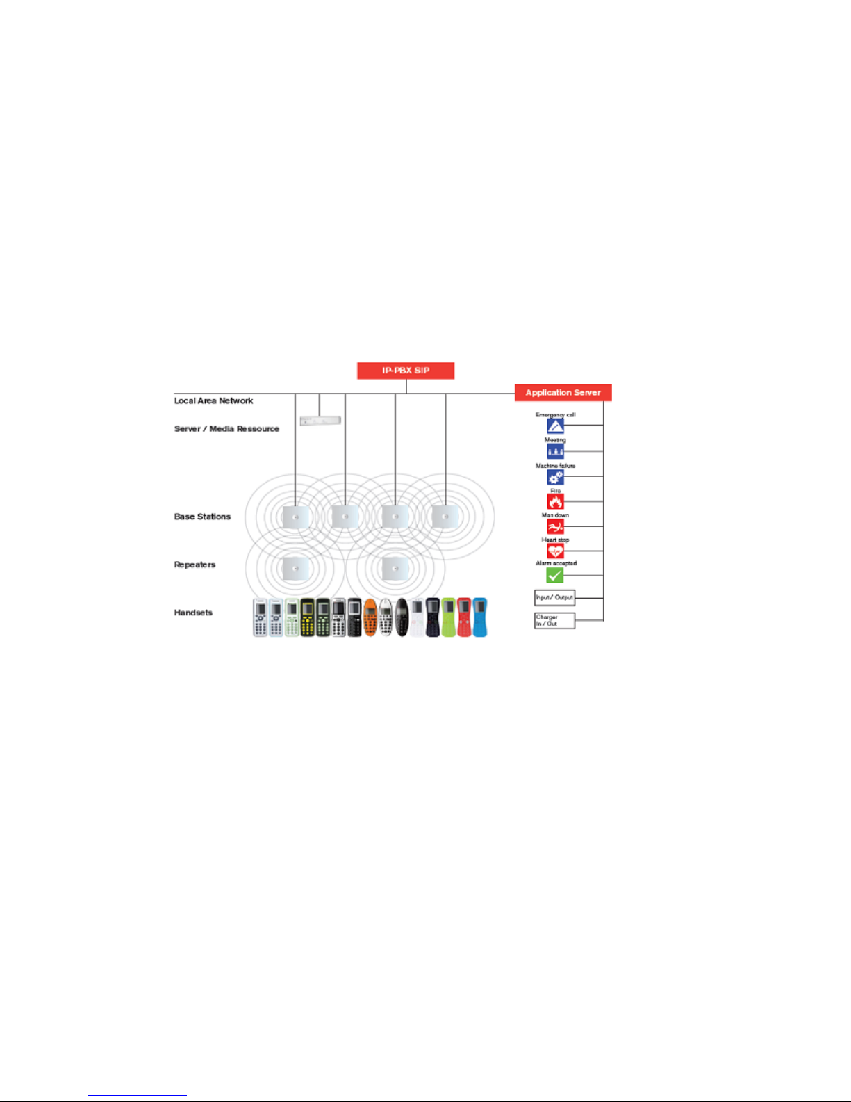
A typical Spectralink IP-DECT Server 6500 configuration includes a number of the following
components, in addition to the Spectralink IP-DECT Server 6500:
• Media resources
• Base stations
• Repeaters
Figure 1 Overview of the Whole Solution
The IP-PBX SIP is also known as the call handler. Throughout this document the term call handler
is used.
Page 11

Spectralink IP-DECT Server 6500 Installation and Configuration Guide
14215700 Version 3.0
April, 2014 9
Solution Components
Spectralink IP-DECT Server 6500
The following is an overview of the system capacity of the Spectralink IP-DECT Server 6500
.
*If secure RTP is enabled, the maximum number of simultaneous calls decreases to 24.
The Spectralink IP-DECT Server 6500 controls the wireless infrastructure. It manages media
resources, base stations, repeaters and the IP interface to the call handler.
The communication protocol between the Spectralink IP-DECT Server 6500 and the call handler
is a SIP line interface.
A Spectralink IP-DECT Server 6500 is installed directly on the LAN and must be managed as part
of the corporate network.
Wireless Bands
The wireless solution supports two wireless bands, allowing operation in various countries and
regions. Supported wireless bands are:
• ETSI DECT (1880-1900 MHz), referred to as DECT
• USA DECT (1920-1930 MHz), referred to as 1G9 or DECT 6.0
• SAM DECT (1910-1930Mhz), referred to as DECT IG9
The wireless band used by a Spectralink IP-DECT Server 6500 solution is determined by the base
stations and handsets ordered with the solution.
Table 2 Overview of System Capacity
Description Capacity
Max. number of base stations.
A minimum of 1 base station is required, as the Spectralink IP-DECT
Server 6500 does not have a built-in radio.
255
Max. number of simultaneous calls on each base station 11
Max. number of repeaters on each base station 3
Max. number of simultaneous calls on a Spectralink IP-DECT Server
6500/media resource (G.711, G.726 and G.729)
32
Max. number of media resources 32*
Max. number of simultaneous calls with 32 media resources 1024
Max. number of registered handsets 4096
Page 12

Spectralink IP-DECT Server 6500 Installation and Configuration Guide
14215700 Version 3.0
April, 2014 10
Spectralink Media Resource
The media resource is a print board that is placed within the same rack next to the Spectralink
IP-DECT Server 6500 board. Up to 2 media resources can be placed in the same rack that houses
the Spectralink IP-DECT Server 6500 board.
The media resource performs media conversion between the call handler and the Spectralink
IP-DECT Server 6500 and is the media termination point for incoming and outgoing calls.
Each Spectralink IP-DECT Server 6500 contains one built in media resource. The Spectralink
IP-DECT Server 6500 can support a total of 32 media resources. Each media resource adds 32
voice channels. The maximum number of simultaneous calls for a fully loaded system is 1024
calls at the same time. If secure RTP is enabled, however, the number of voice channels
supported by each media resource decreases to 24.
Spectralink Base Station
The base stations are positioned in the area to create coverage for DECT handset’s ability to make
and receive calls and messages. The base station contains internal antennas and has 12
channels. One channel is used for synchronization and 11 channels can be used simultaneously
as speech channels. A base station is able to synchronize with other base stations. When the base
station is synchronized with other base stations, a person speaking in a handset can move
between base stations without any interference. This is known as seamless handover.
LAN transmission length is up to 100 meters/329 feet according to IEEE 802.3u on a twisted pair
cable, minimum cat.5e. The base station can be powered by a power supply or by PoE. The base
station is a class 1 PoE device (802.3af) and must be powered accordingly (maximum power
supply consumption 3.0W according to PoE 802.3af). The radius coverage of the base station is
up to 90 meters/295 feet indoor and up to 300 meters/984 feet outdoor, with a handset in
line-of-sight.
Coverage area decreases depending on choice of building materials and obstructive elements. To
ensure proper coverage in the areas required, it is necessary to conduct a site survey and
deployment by certified technicians. For more information about deployment, refer to the online
Deployment Guide.
Spectralink Repeater
The repeater can be used to extend the coverage area in a wireless solution. The wireless
repeater is used in areas with limited voice traffic, where cabling is difficult. The repeater does not
increase the number of traffic channels, but increases the coverage area established with the base
station. Up to three repeaters can be placed in cascade formation directing coverage in a certain
direction.
The base station can support up to 3 repeaters.
Spectralink Handset
The handset is a portable unit compatible with DECT GAP standard.
The handset is designed to provide the subscriber with most of the features available for a wired
phone, in addition to its roaming and handover capabilities.
Page 13

Spectralink IP-DECT Server 6500 Installation and Configuration Guide
14215700 Version 3.0
April, 2014 11
The Spectralink IP-DECT Server 6500 supports up to 4096 registered handsets.
Auto Login and Handover
Auto login refers to the ability to log on to more than one system, enabling you to use the same
handset on up to 15 different systems. If a handset is subscribed to two or more systems, you can
use Auto Login.
• Auto Login is used if a handset is subscribed to two or more systems.
Handover refers to the ability to move between the coverage areas of different radio units on the
same system while talking, without interruptions in the conversation.
Requirements for the Spectralink IP-DECT Server 6500
Solution
This section provides information about the environmental and electrical requirements and
software requirements for the Spectralink IP-DECT Server 6500 solution.
Spectralink IP-DECT Server 6500/Spectralink Media Resources
Environmental Requirements
The installation area must:
• be clean, free of traffic and excess dust, dry, and well ventilated
• be within the temperature ranges of 10°C and 40°C/50°F and 104°F
• be between 20% and 80% non-condensing relative humidity
Note
The installation area must be of sufficient height from the floor to prevent water damage. 1U
rack space in a 19" cabinet or respective space on the wall when mounting the KWS 6500 in
vertical position on a wall.
Page 14

Spectralink IP-DECT Server 6500 Installation and Configuration Guide
14215700 Version 3.0
April, 2014 12
Spectralink Base Stations and Spectralink Repeaters
Environmental Requirements
• Avoid installing base stations and repeaters on large concrete or marble columns because
these columns affect radio coverage. If possible, place the base station a minimum of one
meter/3.3 feet from these types of columns.
• Do not install a base station or repeater with the antenna housings near metal objects. Be
careful not to damage existing wiring or panels.
• Do not position base stations and repeaters in ducts, plenums, or hollow spaces used to
transport environmental air except where the duct, plenum or hollow space is created by a
suspended ceiling having lay-in panels. When you need more than one base station in a cell
to meet traffic requirements, position the base stations at the same cell center.
• Keep the base station and repeater away from steel constructions.
• Do not position base stations and repeaters directly on metallic surfaces. If possible, place the
base station a minimum of one meter/3.3 feet from these types of surfaces.
• Do not position base station and repeaters behind furniture.
• Only position base stations and repeaters where the signal is needed.
• The installation area must be clean, free of traffic and excess dust, dry, and well ventilated.
• The installation area must be within the temperature ranges of 10°C and 40°C/50°F and 104°F.
• The installation area must be between 20% and 80% non-condensing relative humidity.
• Minimum distance between two base stations varies depending on material and construction
of buildings, but there must always be synchronization chains and radio coverage overlap
between the two base stations or handover between radio units. The time it takes a person to
cross the common coverage area must be 10 seconds or more, as the handset needs time to
scan for an alternative base station.
Electrical Requirements for Base Station
The following electrical requirements must be met:
• The base station operates on standard twisted pair ethernet cable - e.g. minimum Cat.5e - to
prevent disturbances from other equipment.
• Maximum power supply consumption is 3.0W (IEEE 802.3af class 1 device).
• The max. radiated output power for the antenna is 10mW e.i.r.p/channel.
• The supplied power (power supply) for the charger must be 110 V to 120 V
• V ac nominal (or 220 V to 230 V ac nominal), 50/60 Hz.
Page 15

Spectralink IP-DECT Server 6500 Installation and Configuration Guide
14215700 Version 3.0
April, 2014 13
Electrical Requirements for Repeater
• The supplied power (power supply) for the charger must be 110 V to 120 V ac nominal (or 220
V to 230 V ac nominal), 50/60 Hz.
Spectralink Handsets
Environmental Requirements
• The area where the handset is used must be within the temperature ranges of 0°C and
40°C/32°F and 104°F.
• For correct battery charging, the room temperature must be between 0°C and 40°C/0°F and
104°F. Therefore, the handset must not be placed in direct sunlight. The battery has a built-in
heat sensor which will stop charging if the battery temperature is too high.
• For battery information, refer to the handset user guide.
• The area where the handset is used must be between 20% and 80% non-condensing relative
humidity.
Electrical Requirements
The following electrical requirement must be met:
• The supplied power (power supply) for the charger must be 110 V to 120 V ac nominal (or 220
V to 230 V ac nominal), 50/60 Hz.
Spectralink Maintenance Software
Software Requirements
The following is required to run the handset and repeater installation and maintenance tools.
• OS: Windows XP or newer
Installation Prerequisites
Before you start the installation you need to find the following information and perform the
following tasks:
Note
Ensure that a site survey and deployment have been conducted and that the installer has
access to these plans before proceeding any further. For more information about deployment,
refer to the Deployment Guide that comes with the Deployment Kit.
Page 16

Spectralink IP-DECT Server 6500 Installation and Configuration Guide
14215700 Version 3.0
April, 2014 14
• ARI codes (serial numbers) for the Spectralink IP-DECT Server 6500 (see label on the rear of
the KWS unit)
• Serial numbers for handsets.
• AC codes (authentication codes)
The AC is a customer-defined optional subscription pin code of a maximum of eight digits for
the individual handset. The AC can be used when connecting the handset to the KWS.
• Repeaters:
Mark each repeater with the number of the related base station. This way you can easily
configure the system on site.
• Handsets:
To use the handsets, you must first install the radio infrastructure, e.g. base stations and
repeaters to transmit and receive radio signals to and from the handsets. There are no direct
connections between the handset and the system.
• Charging battery
When charging the handset battery for the first time, leave the handset in the charger for 14 16 hours to ensure that the battery is fully charged and the handset ready for use. Refer to the
handset user guide for more information.
Page 17

Spectralink IP-DECT Server 6500 Installation and Configuration Guide
14215700 Version 3.0
April, 2014 15
Chapter 3: Installing Spectralink IP-DECT
Server 6500 and Spectralink Media
Resource
This section provides a description of the Spectralink IP-DECT Server 6500 and media resource.
The section also provides information about resetting the Spectralink IP-DECT Server 6500
hardware using the Reset button on the Spectralink IP-DECT Server 6500/media resource print
board.
Before you install the equipment, ensure that a site planner defines the locations of the Spectralink
IP-DECT Server 6500 and media resources.
For outdoor installations, the following items should be present in every box containing a
Spectralink Wireless Server 600v3:
• Spectralink Wireless Server 600v3
• Two mounting screws and anchors
Description
Types and Part Numbers
The following table includes a list of available Spectralink IP-DECT Server 6500 and their part
numbers.
Note
The installation of a media resource is optional. Installation of a media resource will augment
the number of simultaneous voice calls supported by a stand-alone server. The Spectralink
IP-DECT Server 6500 comes with one build-in media resource.
Table 3 Spectralink IP-DECT Server 6500 Part Numbers
Variants of Spectralink IP-DECT Server 6500 Part Number
Spectralink IP-DECT Server 6500 Rack (two empty slots) 02350000
Page 18
Spectralink IP-DECT Server 6500 Installation and Configuration Guide
14215700 Version 3.0
April, 2014 16
Spectralink Media Resource Types and Part Numbers
The following table includes a list of available media resources and their part numbers.
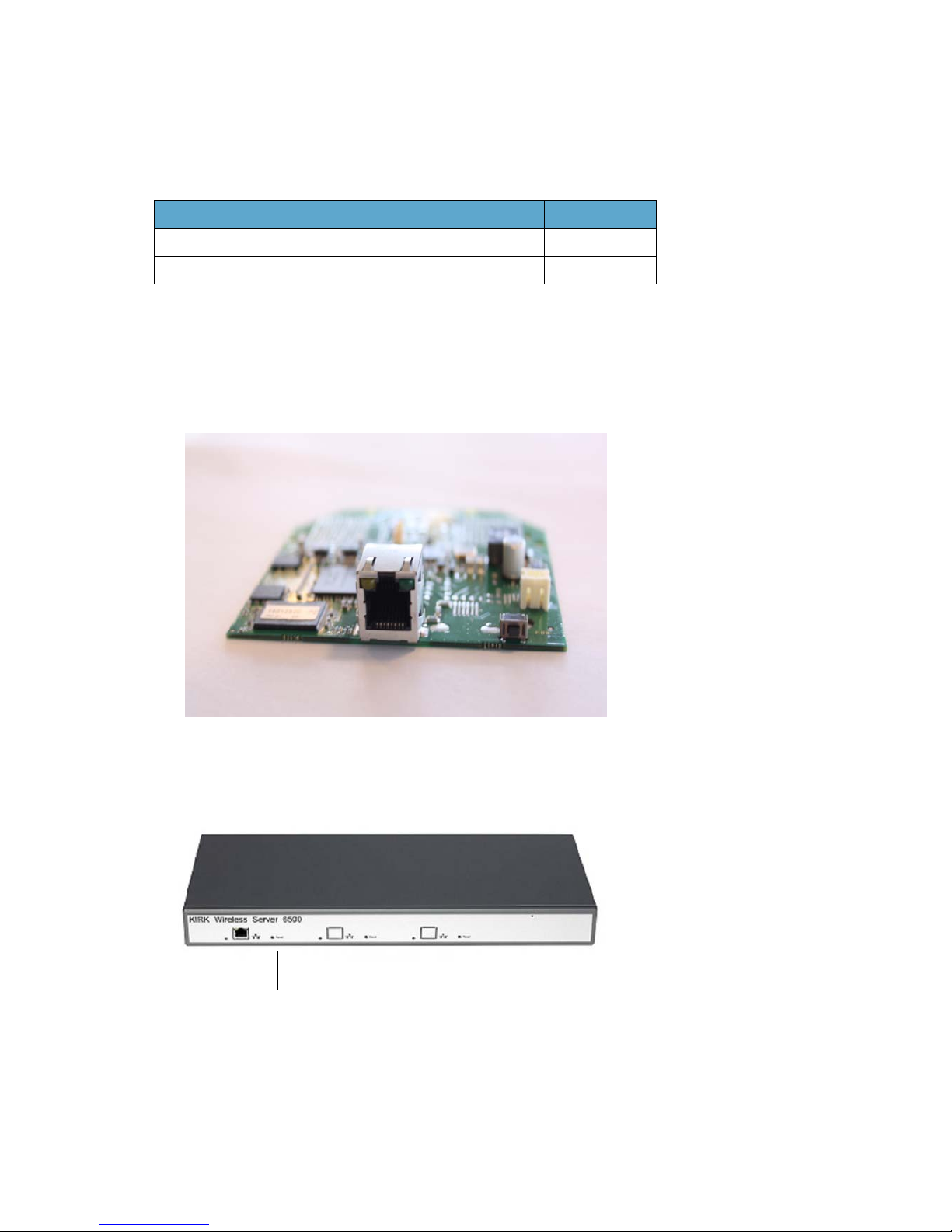
Spectralink IP-DECT Server 6500/Spectralink Media Resource Appearance and
Components
Figure 2 Add-on media resource for empty slot in a KWS 6500 Rack
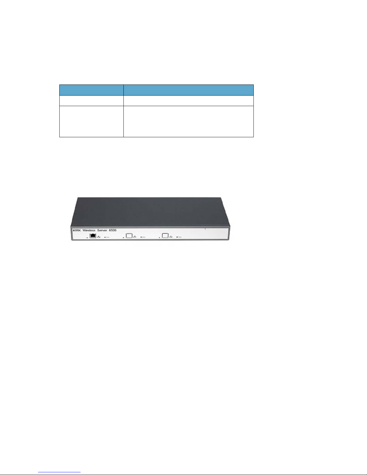
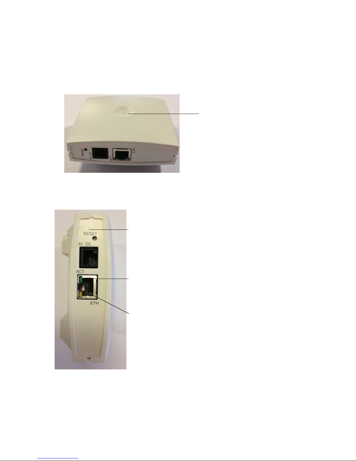
The Spectralink IP-DECT Server 6500/media resource front includes the following (see figure
below).
Figure 3 Spectralink IP-DECT Server 6500/Media Resource - Front
Table 4 Spectralink Media Resource Part Numbers
Variants of Spectralink Media Resources Part Number
Spectralink Media Resource 02344400
Spectralink Media Resource mounted in 19” in Rack 02351000
Reset button
Page 19
Spectralink IP-DECT Server 6500 Installation and Configuration Guide
14215700 Version 3.0
April, 2014 17
Spectralink IP-DECT Server 6500/Spectralink Media Resource LED Indicators
Front Faceplate
The Spectralink IP-DECT Server 6500/media resource front cover has one indicator describing
the faults and failures of the device. The indicator is off when the Spectralink IP-DECT Server
6500/media resource is not powered. The LED flashes when the Spectralink IP-DECT Server
6500/media resource initializes. The indicator is on when the Spectralink IP-DECT Server
6500/media resource is operating.
Front Lan Port
Spectralink IP-DECT Server 6500/Spectralink Media Resource - Reset Button
It is possible to restart or reset the Spectralink IP-DECT Server 6500/media resource by pressing
the Reset button on the front of the Spectralink IP-DECT Server 6500/media resource.
Table 5 LED Indicator Description - Front Faceplate
LED Indicator Meaning
Steady green OK and idle
Slow green flashing OK and active voice call
Fast green flashing Active, in operation with the maximum active
connections (busy)
Slow red flashing Missing media resource or base station (if it is a
media resource: missing connection to
Spectralink IP-DECT Server 6500)
Fast red flashing Error
Steady red Reset/shutdown in progress
Steady red for 5 seconds
followed by fast red flashing
Reset to factory settings
Table 6 LED Indicator Description - Front Lan port
LED Indicator Meaning
LINK Indicator - yellow Link layer software has established
connection
Activity Indicator - green
flashing
Activity
Page 20
Spectralink IP-DECT Server 6500 Installation and Configuration Guide
14215700 Version 3.0
April, 2014 18
Resetting the Spectralink IP-DECT Server 6500/Spectralink Media Resource Hardware
The following table contains a description of the different actions that take place when you press
the Reset button.
Installation
The Spectralink IP-DECT Server 6500/media resource is mountable in a rack.
Figure 4 Spectralink IP-DECT Server 6500/Media Rack Mounting
1 Mount the two wings with the screws. If you are mounting the Spectralink IP-DECT Server
6500 on a wall, twist the wings 90° degrees.
2 Mount the cabinet in the 19" rack or on the wall, Screws and nuts/rawl plugs are not supplied.
3 Connect the RJ45 ethernet plug to the front of the cabinet. All servers and media resources
must be connected to a switch port. Installed Media Resources must have their own switch
port.
4 Connect the power on the back of the cabinet.
Table 7 Reset Button Description
Press button Action
Short press (2 to 5 sec.) System restarts when button is released.
Long press (5 to 9 sec.)
until front LED flashes
red, then release button
Resets the system to factory default settings (original
IP settings and empty user data base) and restarts the
system.
Firmware version is not affected.
Page 21
Spectralink IP-DECT Server 6500 Installation and Configuration Guide
14215700 Version 3.0
April, 2014 19
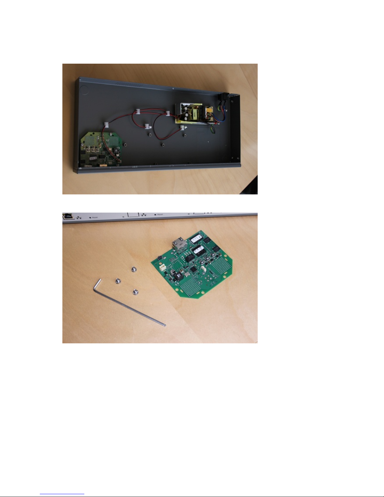
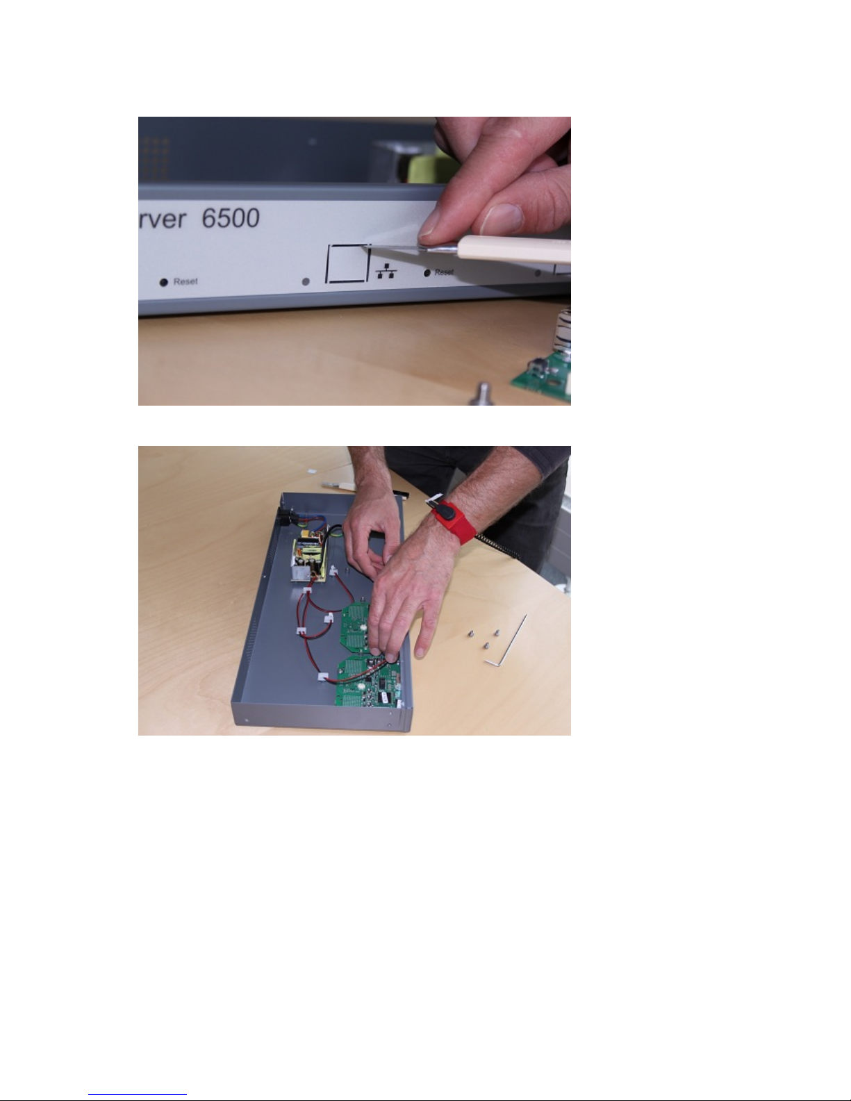
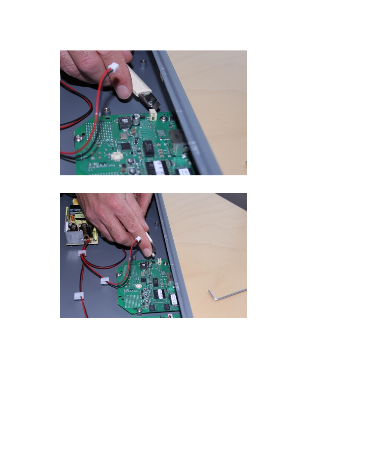
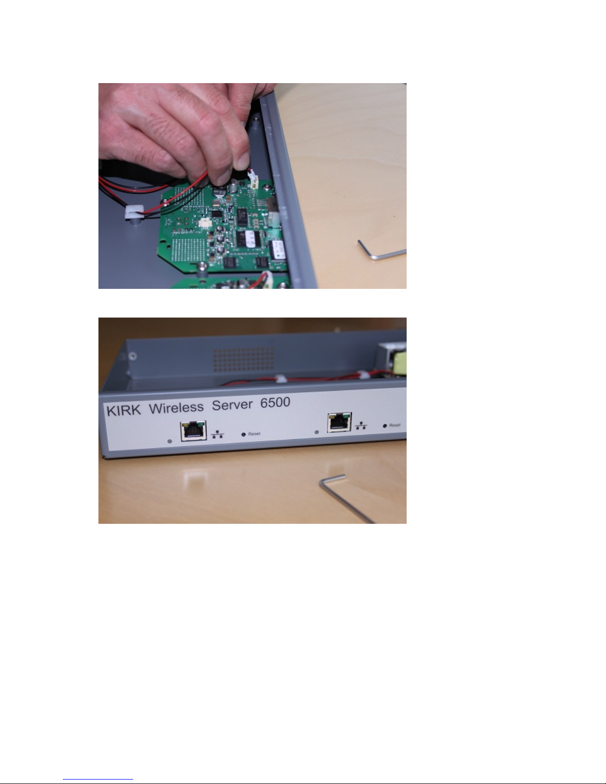
The following images illustrate how to install the media resource.
Page 22
Spectralink IP-DECT Server 6500 Installation and Configuration Guide
14215700 Version 3.0
April, 2014 20
Page 23
Spectralink IP-DECT Server 6500 Installation and Configuration Guide
14215700 Version 3.0
April, 2014 21
Page 24
Spectralink IP-DECT Server 6500 Installation and Configuration Guide
14215700 Version 3.0
April, 2014 22
Page 25

Spectralink IP-DECT Server 6500 Installation and Configuration Guide
14215700 Version 3.0
April, 2014 23
Chapter 4: Installing Spectralink Base
Station
This section provides information about the base station and how to install it.
Before you install the equipment, ensure that a site planner defines the location of the base
stations.
Spectralink IP-DECT Base Station Description
Spectralink Base Station Provides DECT Coverage to Spectralink Handsets
The base station is a compact device that contains RF circuitry and transmit/receive antennas.
The main function of the base station is to provide audio and data communication between the
handsets and the Spectralink IP-DECT Server 6500. The base station supports 11 RF channels
for speech channels.
DECT coverage is provided according to the band standard at the site:
• Base station - DECT provides 11 RF channels of 1.8 GHz, DECT standard, used in Europe,
Australia and South America.
• Base station - USA DECT provides 11 RF channels of the 1.9 GHz, USA DECT standard, used
in North America.
Spectralink Base Station Types and Part Numbers
The base station contain RF circuitry that comply with the local band standards: UPCS, DECT, or
ETSI DECT. The following table includes a list of available base stations and their part numbers.
Note
The base station is also termed by some manufacturers as the RFP (Radio Fixed Part)
Table 8 Spectralink Base Station Part Numbers
Variants of Spectralink Base Stations Part Number
Spectralink IP Base Station 12 1.8 GHz (conforms with
standard DECT markets)
02337300
Spectralink IP Base Station 12 1.9 GHz (for North
America)
02337301
Page 26
Spectralink IP-DECT Server 6500 Installation and Configuration Guide
14215700 Version 3.0
April, 2014 24
Spectralink Base Station Appearance and Components
The base station front cover includes the following:
• LED that indicates the operating status of the unit
Figure 5 Base Station - Front view
The base station front includes the following (see figure below).
Figure 6 Base Station - Front
LED
ETH port (power
supply by PoE)
LINK/Activity
Indicator
Reset Button
Page 27

Spectralink IP-DECT Server 6500 Installation and Configuration Guide
14215700 Version 3.0
April, 2014 25
Spectralink Base Station LED Indicators
Front Cover
The base station front cover has one indicator describing the base station faults and failures. The
indicator is off when the base station is not powered. The LED flashes when the base station
initializes. The indicator is on when the base station is operating.
LAN Port on Face Plate
Figure 7 LED Indicator Description - LAN port
Spectralink Base Station - Reset Button
It is possible to restart or reset the base station by pressing the Reset button on the bottom of face
plate of the base station.
Table 9 LED Indicator Description - Front Cover
LED Indicator Meaning
Steady green OK and idle
Slow green flashing OK and active voice call
Fast green flashing No sync over air possible, or sync
master is not available.
Slow red flashing Missing media resource or base
station (if it is a media resource:
missing connection to Spectralink
IP-DECT Server 6500)
Fast red flashing Error
Steady red Reset/shutdown in progress
Steady red for 5 seconds
followed by fast red flashing
Reset to factory settings
Table 4-1
LED Indicator Meaning
LINK Indicator - yellow Link layer software has
established connection
LINK Indicator - green flashing Activity
Page 28
Spectralink IP-DECT Server 6500 Installation and Configuration Guide
14215700 Version 3.0
April, 2014 26
Resetting the Spectralink Base Station Hardware
The following table contains a description of the different actions that take place when pressing
the Reset button.
Installing the Spectralink Base Station
The base station is suitable for mounting indoors on a wall.
Wall Mounted (Vertical) Installation RF Coverage
For best RF coverage, the base station must be mounted vertically on walls. The antennas must
always be kept perpendicular to the floor.
Table 5 Reset Button Description
Press button Action
Short press (2 to 5 sec.) System restarts when button is
released.
Long press (5 to 9 sec.) until
front LED flashes red, then
release button
Resets the system to factory default
settings (original IP settings (DHCP)
and empty user data base) and
restarts the system.
Firmware version is not affected.
Note
Before you begin the installation, determine the position of the base station for best coverage.
The coverage depends on the construction of the building, architecture, and the choice of
building materials.
Caution
The base station must not be installed at any angle other than vertical.
Caution
Do not mount the base station on soft surfaced walls such as those covered with canvas, metal
or sponge-like materials
Page 29
Spectralink IP-DECT Server 6500 Installation and Configuration Guide
14215700 Version 3.0
April, 2014 27
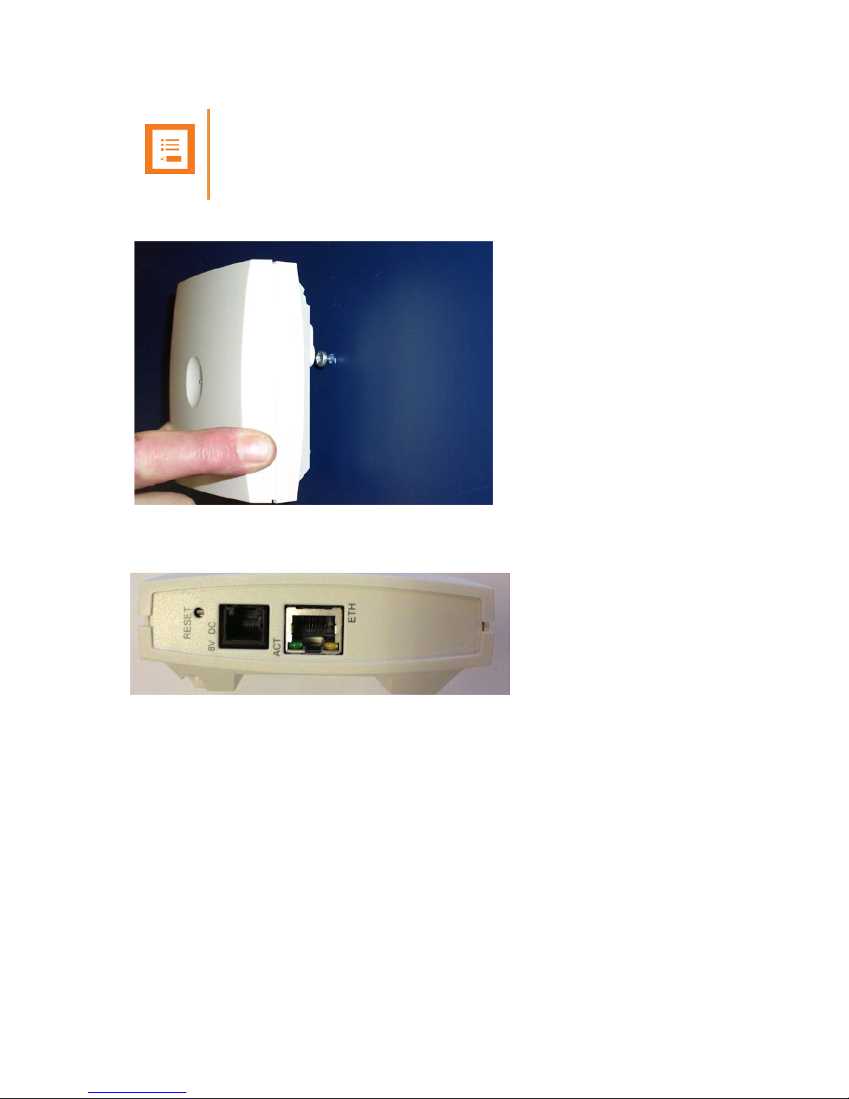
1 Mount the base station on the wall using the anchors and screws accompanying the product.
Figure 8 Base Station Wall Mounting
1 Connect the RJ45 plug to the ethernet connector at the bottom of the base station.
44
Figure 9 Base Station - Ethernet Connector
Recording the Installation Information
After completing the installation of the base stations, record the location of each base station and
add a descriptive text in the Administration Page of the Spectralink IP-DECT Server 6500 under
Administration/Base stations.
Note
When you place the base station on the screws, ensure that the screws do not touch the
printed circuit board..
Page 30

Spectralink IP-DECT Server 6500 Installation and Configuration Guide
14215700 Version 3.0
April, 2014 28
Chapter 5: Installing Spectralink Repeater
This section provides information about the repeater and how to unpack and install it. Installing
repeaters requires a software installation as well as a hardware installation.
Before you install the equipment, ensure that a site planner defines the location of the repeaters.
For outdoor installations, the following items should be present in every box containing a
Spectralink Repeater:
• Spectralink Repeater
• Mounting template for indoors installation
• Two mounting screws and anchorsi
Spectralink Repeater Description
Spectralink Repeater Provides DECT Coverage to Spectralink Handsets
The Spectralink Repeater is a building block to be used to extend the coverage area in a
Spectralink solution. The repeater does not increase the number of traffic channels, however it
provides a larger physical spreading of the traffic channels and thereby increases the coverage
area established with the Spectralink Base Stations.The repeaters are mainly used in areas with
limited traffic.
The Spectralink Repeater is available with either 2 or 4 voice channels. It is wireless and does not
need physical connection to the Spectralink Wireless Server, which makes it easy to install. The
repeaters can be supplied with an external antenna making it possible to create radio coverage in
a remote area without cabling to the rest of the installation.
The RF communication is provided according to the band standard at the site:
Caution
For outdoor installations you need to mount the Spectralink Repeater in spots to prevent
influenze from wether conditions.
Note
The repeater is also termed by some manufacturers as the WRFP (Wireless Radio Fixed Part).
Page 31

Spectralink IP-DECT Server 6500 Installation and Configuration Guide
14215700 Version 3.0
April, 2014 29
• Repeater - DECT provides four RF channels of 1.8 GHz, DECT standard, used in Europe,
Australia and South America.
• Repeater - USA DECT provides four RF channels of 1.9 GHz, USA DECT standard, used in
North America.
Spectralink Repeater Types and Part Numbers
The repeater contains RF circuitry that comply with the local band standards: UPCS, DECT, or
ETSI DECT. The wall mounted repeater and the ceiling mounted repeater is available as a full slot
repeater. A full slot repeater covers four simultaneous speech channels. These channels are
borrowed from the attached base station, and are not additional channels to the total number of
channels on the system.The Spectralink Repeater can be installed either indoors or outdoors.
• Indoors. The Spectralink Repeater is suitable for mounting indoors on a wall or ceiling.
• Outdoors. The Spectralink Repeater can be placed in a weatherproof, environmentally
protected unit suitable for installation on external walls, poles etc.
The following table includes a list of available repeaters and their part numbers.
Table 6 Repeaters and Part Numbers
Spectralink Repeater - Appearance and Components
The repeater connection panel includes the following:
Variants of Spectralink Repeaters Part Number
Spectralink Repeater Multi Cell 1.8 GHz w/external
antenna, 2 Channel
0244 0000
Spectralink Repeater Multi Cell 1.9 GHz w/external
antenna, 2 Channel
0244 1000
Spectralink Repeater Multi Cell 1.8 GHz w/external
antenna, 2 Channel
0244 1600
Spectralink Repeater Multi Cell 1.9 GHz w/external
antenna, 2 Channel
0244 0200
Spectralink Repeater Multi Cell 1.8 GHz w/o external
antenna, 2 Channel
0244 1100
Spectralink Repeater Multi Cell 1.9 GHz w/o external
antenna, 2 Channel
0244 1200
Spectralink Repeater Multi Cell 1.8 GHz w/0 external
antenna, 2 Channel
0244 4601
Spectralink Repeater Multi Cell 1.9 GHz w/0 external
antenna, 2 Channel
0244 8200
Page 32

Spectralink IP-DECT Server 6500 Installation and Configuration Guide
14215700 Version 3.0
April, 2014 30
• Power supply connection (connection for programming the repeater as well). The power
supply for the repeater must ordered separately (Part no. 84642602).
• Antenna connector for repeaters supplied with external antenna connection.The external
antenna including the antenna cable must be ordered separately (part no. 02319507).
• LED that indicates whether or not the unit is functioning.
Figure 10 Repeater
Spectralink Repeater LED Indicators
The repeater has one LED indicator describing the repeater operations: The indicator is off when
the repeater is not powered. When the LED flashes after the repeater has been powered, sync
has still not been established. As soon as sync has been established the LED is on. Each time a
handset connects to the repeater, the LED flashes shortly. Each time a handset makes handover
to a repeater, the LED flashes shortly.
Installing the Spectralink Repeater
Before beginning the installation, determine the position of the repeater for best coverage. The
coverage depends on the construction of the building, architecture, and the choice of building
materials.
LED
Page 33

Spectralink IP-DECT Server 6500 Installation and Configuration Guide
14215700 Version 3.0
April, 2014 31
Environmental requirements
• Avoid installing repeaters on large concrete or marble columns because these columns affect
radio coverage. If possible, place the base station a minimum of one meter/3.3 feet from these
types of columns.
• Do not install a repeater with the antenna housings near metal objects. Be careful not to
damage existing wiring or panels.
• Do not position repeaters in ducts, plenums or hollow spaces used to transport environmental
air except where the duct, plenum or hollow space is created by a suspended ceiling having
lay-in panels.
• Keep the repeater away from steel constructions.
• Do not position repeaters directly on metallic surfaces. If possible, place the base station a
minimum of one meter/3.3 feet from these types of surfaces.
• Do not position repeaters behind furniture.
• Only position repeaters where the signal is needed.
• The installation area must be clean, free of traffic and excess dust, dry, and well ventilated.
• The installation area must be within the temperature ranges of 10°C and 40°C/50°F and 104°F.
• The installation area must be between 20% and 80% non-condensing relative humidity.
For best RF coverage, the repeater must be mounted vertically on walls. The antennas must
always be kept perpendicular to the floor.
Note
The repeater does not add channels, it only adds additional coverage area.
Note
The repeater can be registered on the system 1) when placed within the coverage area of a
base station 2) when placed within the coverage area of an already-installed repeater or 3)
when placed outside the coverage area using an external antenna.
Caution
The repeater must not be installed at any angle other than vertical. If the repeater is placed
upside-down, the coverage area of the repeater is decreased by 40 - 50% and it might not
transmit or receive effectively.
Page 34

Spectralink IP-DECT Server 6500 Installation and Configuration Guide
14215700 Version 3.0
April, 2014 32
Figure 11 Connect Power to the Bottom of the Repeater and External Antenna Cable to the Rear of the Repeater
1 Connect the power supply cable into the RJ9 (4P4C) connector in the bottom of the repeater.
For repeaters with external antenna, connect the external antenna cable to the antenna
connector in the rear of the repeater as well.
2 Mount the repeater onto the wall using the screws accompanying the repeater.
Figure 12 Repeater and External Antenna Installed on the Wall
1) External Antenna
Only for repeaters supplied with external antenna connection)
The external antenna cable is only for repeaters supplied with external antenna connection.
2) Repeater
1) 2)
Page 35

Spectralink IP-DECT Server 6500 Installation and Configuration Guide
14215700 Version 3.0
April, 2014 33
Note: The external antenna used for the transmitter is to be fixed-mounted on indoor permanent
structures providing a separation distance of at least 20 cm / 8 inches from all persons during normal
operation and must not be co-located or operating in conjunction with any other antenna or transmitter.
The maximum radiated output power is 1W e.i.r.p. For more information and technical support, please
refer to www.Spectralink.com.
Recording the Installation Information
After completing the installation of the repeaters, record the location of each repeater.
Checking Indicators
Verify that the repeater LED indicator is continuously on, indicating that the repeater is functional.
Powering the Spectralink Repeater
Power Options
The power supply for the repeater is 9VDC, 300mA.
Programming with the Spectralink Programming Kit
This section describes how you program the Spectralink Repeater.
Content of the Spectralink Programming Kit Repeater
The Programming Kit Repeater (Part no. 02319508) consists of a splitter and a serial cable.
Note
For programming the repeater you also need the programming software (ServiceTool) and the
power supply for the repeater. The ServiceTool is not part of the Programming Kit Repeater
but can be downloaded from www.Spectralink.com. The power supply for the repeater is to be
ordered separately (Part no. 84642602).
Page 36
Spectralink IP-DECT Server 6500 Installation and Configuration Guide
14215700 Version 3.0
April, 2014 34
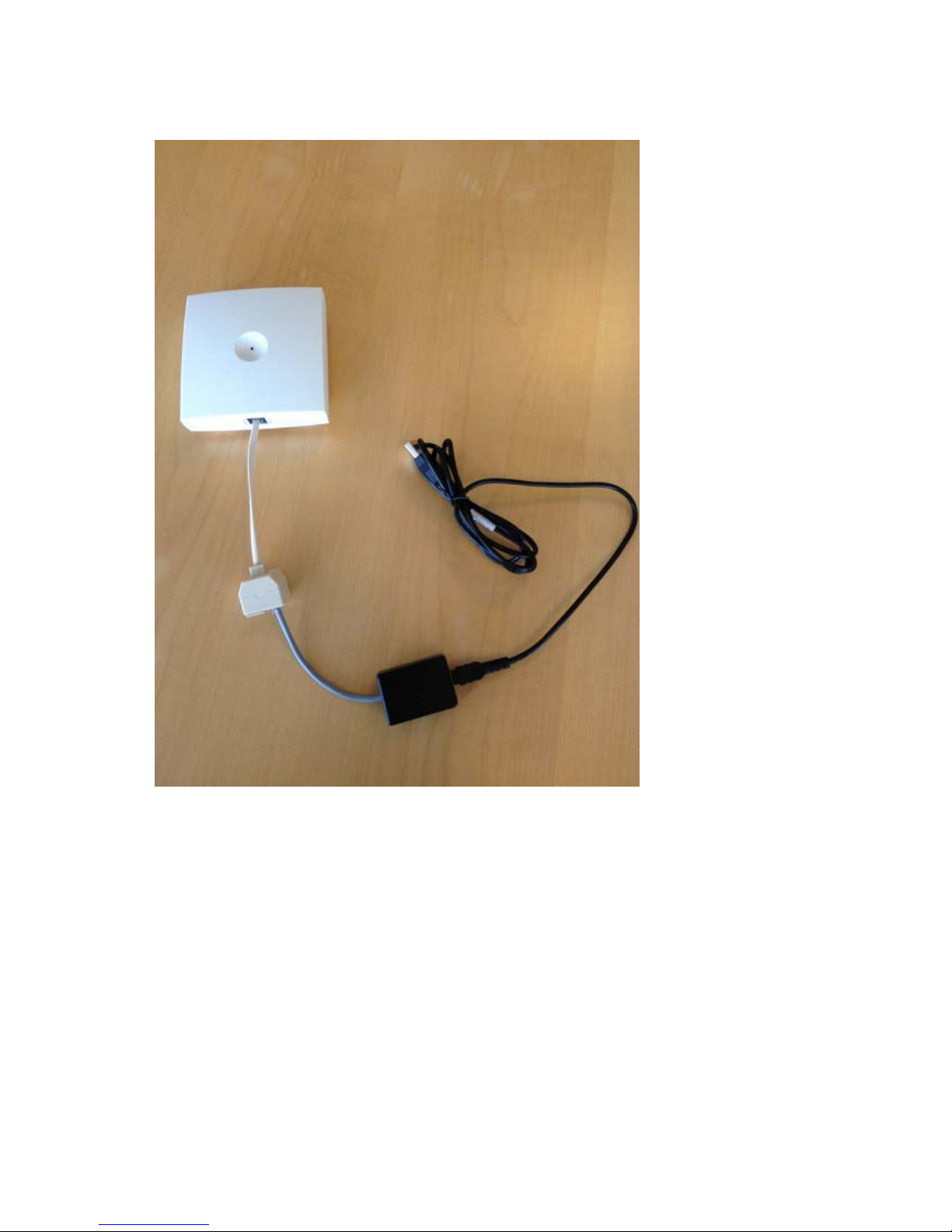
Figure 13 Programming Kit Repeater
Set up of the Hardware for Repeater Programming
Before you set up the hardware ensure that you have an appropriate power supply that meets
local requirements.
Follow the set up order closely.
1 Unplug the repeater power supply and insert the splitter.
2 Connect the repeater power supply to the splitter and the mains. LED flashes.
3 Connect the serial cable to the splitter and Com port of your computer.
The repeater is now ready for programming via the ServiceTool.
Page 37
Spectralink IP-DECT Server 6500 Installation and Configuration Guide
14215700 Version 3.0
April, 2014 35
Programming the Spectralink Repeater with the ServiceTool
The ServiceTool is the tool you access from your desktop and use for repeater programming,
handset adjustment and software download to the handset and repeater.
The ServiceTool identifies the type of repeater, and with this software it is possible to program the
Spectralink Repeater to connect to the Spectralink DECT Radio Infrastructure solutions.
Before you start programming the repeater, ensure that the repeater is connected to the computer
and the mains.
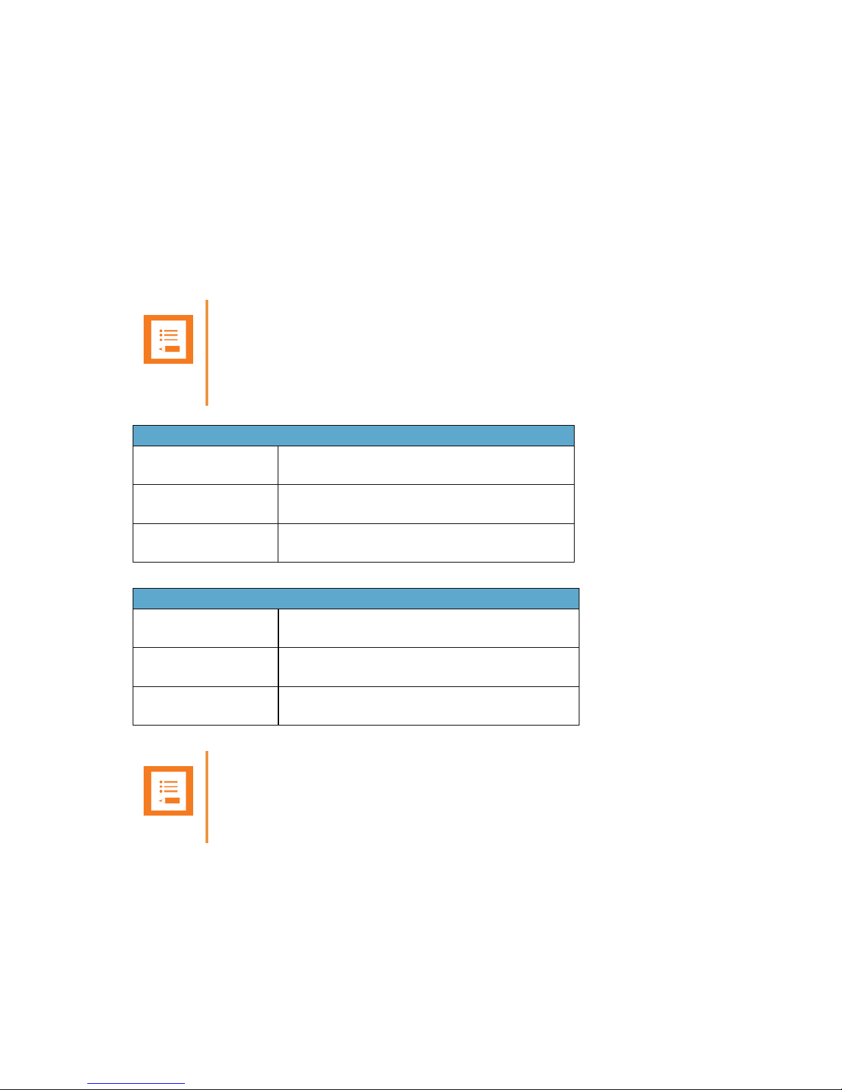
In a multi cell solution, the numbering of the base stations and repeaters has to follow the
numbering in Appendix 1.
Note
Repeater and base station numbers must not be the same. Neither can the repeater have a
number similar to another base station or another repeater in a situation where common
overlap is present between the actual units (Numbers with red colour show where numbering
could be identical between different units). If this occurs, handover between the different units
is not possible.
Numbering of base stations and repeaters in a normal configuration
First repeater No. of base station + 64
Base to synchronize on: Number of base station
Second repeater No. of base station + 128
Base to synchronize on: Number of base station
Third repeater No. of base station + 192
Base to synchronize on: Number of base station
Numbering of repeaters in a repeater jump configuration
First repeater in chain No. of base station + 64
Base to synchronize on: Number of base station
Second repeater in chain No. of base station + 128
Base to synchronize on: Number of previous repeater
Third repeater in chain No. of base station + 192
Base to synchronize on: Number of previous repeater
Note
For programming the repeater you also need the programming software (ServiceTool) and the
power supply for the repeater. The ServiceTool is not part of the Programming Kit Repeater
but can be downloaded from www.Spectralink.com. The power supply for the repeater is to be
ordered separately (Part no. 84642602).
Page 38
Spectralink IP-DECT Server 6500 Installation and Configuration Guide
14215700 Version 3.0
April, 2014 36
For more information about programming the repeater with the ServiceTool, refer to the Help File
in the ServiceTool. The ServiceTool is to be downloaded from www.spectralink.com.
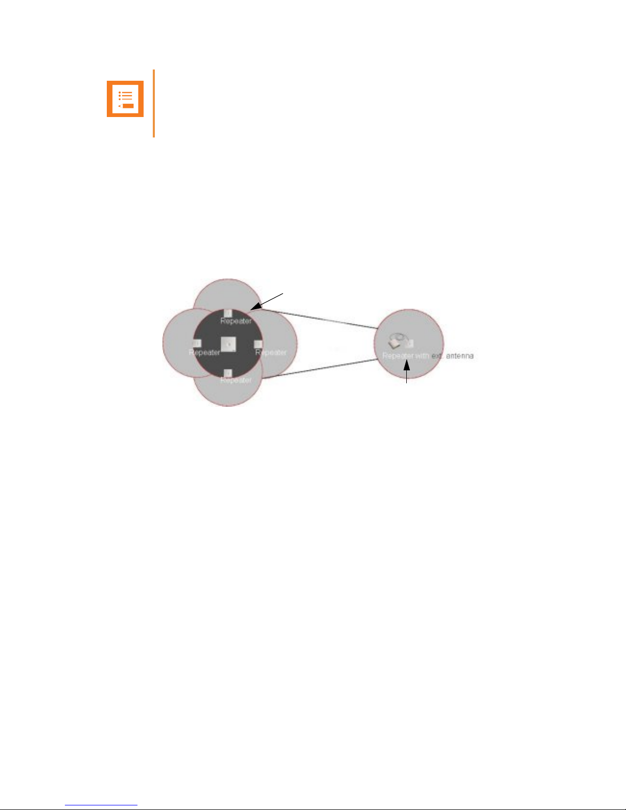
Use of Spectralink Repeater With External Antenna
If radio coverage between a base station and a repeater is not needed, it is possible to
synchronize between the radio units using a repeater with external antenna.
Figure 14 Use of Repeaters
The distance from the repeaters without external antenna to the base station must correspond to
a RSSI loss of maximum 25dB.
Be aware that inside the area named “radio link” there is no radio coverage, and therefore a
wireless handset cannot be used in this area.
The distance between the base station and the repeater with external antenna depends on the
type of antenna used as well as on the signal attenuation created by surroundings such as
buildings, trees, etc.
Synchronization Ways
The repeater with external antenna, 4 channels, can be programmed to obtain synchronization on
two radio units (base station or repeater).
If a situation occurs where the primary sync for some reason breaks down, the repeater will obtain
sync on the alternative sync.
Be aware that the primary sync has priority; the alternative sync is only in use as long as the
primary sync is down.
Note
For programming the repeater you also need the programming software (ServiceTool) and the
power supply for the repeater. The ServiceTool is not part of the Programming Kit Repeater
but can be downloaded from www.Spectralink.com. The power supply for the repeater is to be
ordered separately (Part no. 84642602).
Base
Radio Link
Use of Spectralink
Repeaters without
Use of Spectralink
Page 39

Spectralink IP-DECT Server 6500 Installation and Configuration Guide
14215700 Version 3.0
April, 2014 37
Chapter 6: Basic Network Configuration
This section provides you with information on basic network configuration. Basic network settings
can be derived from a DHCP server or entered manually through TCP/IP Setup.
Using DHCP the device requests and obtains an available IP address from a DHCP server. The
device also obtains other parameters such as the default gateway, subnet mask, DNS server,
Time server and other IP parameters from the DHCP server.
Using manual TCP/IP Setup the IP addresses and other networking parameters are entered
manually through the web based Administration Page. The static IP addresses are unique,
provided and managed by your system administrator.
Recommended Network Configuration
When configuring a Spectralink IP-DECT Server 6500 Solution, it is strongly recommended to
configure:
• Spectralink IP-DECT Server 6500 using static IP address
• Media resources using DHCP
• Base stations using DHCP
If the Spectralink IP-DECT Server 6500 Solution is configured as recommended above, it is
possible to assign options to the DHCP server making it extremely easy to configure all media
resources and base stations.
If the Spectralink IP-DECT Server 6500 is configured using DHCP, it is necessary to assign a
reservation for the device on the DHCP server.
Note
When using DHCP on base stations and media resources, the Spectralink IP-DECT Server
6500 must have either a static IP address or IP address reservations assigned to the DHCP
server.
Note
When the Spectralink Wireless devices are set up to DHCP, you need to use UPnP to
discover the Wireless devices. The devices will appear under Network and Other Devices as
“<device name>-<Serial number> “, for example, Spectralink IP-DECT Server 6500-8442621
or MR6500-84532341.
Page 40

Spectralink IP-DECT Server 6500 Installation and Configuration Guide
14215700 Version 3.0
April, 2014 38
Assigning DHCP Server Options
You can provide information about the static IP address of the Spectralink IP-DECT Server 6500
in the DHCP server through DHCP options. When defining the IP address of the Spectralink
IP-DECT Server 6500 in the DHCP server, all media resources and base stations are configured
automatically.
Below you will find a description of how to assign options to a DHCP server when opening a DHCP
server console (MS 2000/2003 DHCP Server):
• When adding a new class you must enter the following information:
— Display name: Spectralink IP6500
— Description: Spectralink IP-DECT Server 6500 Solution
— ASCII: Spectralink.IP6000 (case sensitive)
• When adding a new option you must enter the following information:
— Name: Spectralink IP-DECT Server 6500
— Type: String
— Code: 43
• Select options 43.
• Enter the IP address of the Spectralink IP-DECT Server 6500.
Assigning DHCP Server Reservations
If the Spectralink IP-DECT Server 6500 is configured using DHCP, it is necessary to assign a
reservation for the device on the DHCP server. For more information about this feature, contact
your network administrator.
Page 41

Spectralink IP-DECT Server 6500 Installation and Configuration Guide
14215700 Version 3.0
April, 2014 39
Chapter 7: Configuring the IP-DECT Server
6500
This section provides you with information on how to power up the Spectralink IP-DECT Server
6500 and connect the unit to a computer. It also provides information on how to configure a
Spectralink IP-DECT Server 6500 through the web based Administration Page using either DHCP
or static IP address.
Discovering the Spectralink IP-DECT Server 6500 via
UPnP
The Spectralink IP-DECT Server 6500 is setup with DHCP enabled by default. You therefore have
to use UPnP to discover the Spectralink IP-DECT Server 6500. The Spectralink IP-DECT Server
6500 will appear under Network and Other Devices as "Spectralink IP-DECT Server 6500-<Serial
number> ", for example Spectralink IP-DECT Server 6500-8442621.
Figure 15 Using UPnP to discover Spectralink IP-DECT Server 6500
Double-click the icon to access the Spectralink IP-DECT Server 6500 web user interface.
Accessing the Web Based Administration Page
The Spectralink IP-DECT Server 6500 can only communicate with the network through a patch
cable connected to a 10/100-Mbit/s Switch port.
Note
The Spectralink IP-DECT Server 6500 is pre-configured to use a DHCP assigned IP address.
If no DHCP server is available, connect directly to the server using a patch cable. Then wait
one minute for the server to fall back to the IP address: 192.168.0.1.
Page 42

Spectralink IP-DECT Server 6500 Installation and Configuration Guide
14215700 Version 3.0
April, 2014 40
Figure 16 Direct connection patch cable (RJ45)
1 Connect the direct connection patch cable to the computer.
2 Connect the patch cable to the LAN port of the Spectralink IP-DECT Server 6500.
How to Access the Administration Page
The web based Administration Page is accessed through a standard web browser.
1 Open a web browser.
2 In the browsers Address bar, type 192.168.0.1 or the IP-address discovered by UPnP, and
then press ENTER.
The Spectralink IP-DECT Server 6500 Administration Page appears.
Note
The LAN port of the Spectralink IP-DECT Server 6500 is a RJ45 connector.
Page 43
Spectralink IP-DECT Server 6500 Installation and Configuration Guide
14215700 Version 3.0
April, 2014 41
Figure 17 Main page of the Administration Page for wireless server
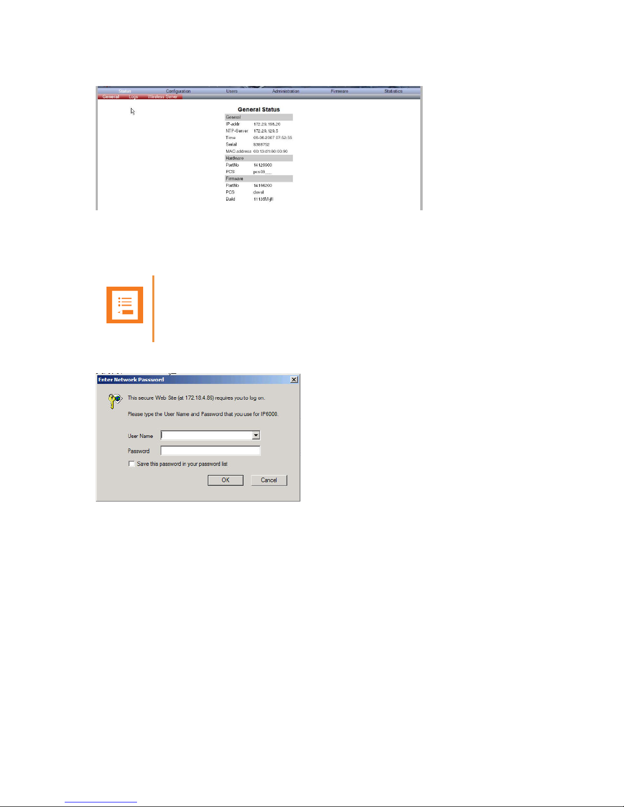
Entering a System User Name and Password
When you access the Administration Page, you need to log on with a user name and a password.
Figure 18 Adm. Page: Enter Network Password dialog box
1 In the User Name field, type admin.
2 In the Password field, type ip6000.
3 Click OK.
Note
The default user name of the system is admin and the default password of the system is
ip6000. It is strongly recommended that you change the password.
Page 44

Spectralink IP-DECT Server 6500 Installation and Configuration Guide
14215700 Version 3.0
April, 2014 42
Configuring a Spectralink IP-DECT Server 6500 Using
Static IP Address
This section describes how to configure a Spectralink IP-DECT Server 6500 using a static IP
address.
Figure 19 Spectralink IP-DECT Server 6500 installation
General Configuration
On the Configuration/General page you define IP, DNS and NTP settings for the Spectralink
IP-DECT Server 6500.
1 Click Configuration, and then click General.
Note
Because the Spectralink IP-DECT Server 6500 is a critical part of the SIP infrastructure, it is
highly recommended that you do not use DHCP. Using a static IP adress is the preferred
method.
Page 45

Spectralink IP-DECT Server 6500 Installation and Configuration Guide
14215700 Version 3.0
April, 2014 43
Figure 20 Adm. Page WS: Configuration/General page
2 Click Use Static IP Address.
3 In the IP Addr field, type the IP address of the Spectralink IP-DECT Server 6500.
4 In the Netmask field, type a new network mask.
Contact your system administrator for more information.
5 In the Gateway field, type the IP address of the default gateway.
The default gateway serves as an access point to another network.
Contact your system administrator for more information.
6 In the MTU field (Maximum Translation Unit), type the size of the largest packet, that your
network protocol can transmit (optional).
7 In the Domain field, type the domain name of the system (optional).
8 In the Server field (under DNS - Domain Name System), type the IP address of the DNS
server (optional).
9 In the Server field (under NTP - Network Time Protocol), type the IP address of the NTP
server from which the system will obtain the current time.
10 From the Time Zone list, select the wanted time zone.
11 Click Save to save your general configuration data.
Wireless Server Configuration
On the Configuration/Wireless Server page you configure the Spectralink IP-DECT Server 6500
to allow subscription. If the system does not allow subscription, it is not possible to subscribe a
handset.
1 Click Configuration, and then click Wireless Server.
Page 46

Spectralink IP-DECT Server 6500 Installation and Configuration Guide
14215700 Version 3.0
April, 2014 44
Figure 21 Wireless Server Configuration
2 Select the Subscription Allowed check box (optional).
Note: If not selected, you cannot subscribe a handset.
3 Click Save.
Built-In Media Resource Configuration
On the Configuration/Media Resource page you configure the built-in media resource.
1 Click Configuration, and then click Media Resource.
Figure 22 Adm. Page WS: Configuration/Media Resource page
2 Select Enable internal if you want to activate the built-in media resource.
3 Click Save.
SIP Configuration
On the Configuration/SIP page you define general SIP settings, information about
authentication, DTMF signalling, message waiting indication and media.
1 Click Configuration, and then click SIP.
Figure 23 Adm. Page WS: Configuration/SIP page
Page 47

Spectralink IP-DECT Server 6500 Installation and Configuration Guide
14215700 Version 3.0
April, 2014 45
2 Apply the desired values as described in the following table
Field Explanation Required Optional
SIP Configuration - General
Local Port Enter the local port number. The default
local port number is 5060.
The local port is the port on which the
IP-DECT Server 400 listens for incoming
SIP-signalling
x
Transport
Transport mechanism used for SIP
messages. possible settings: UDP, TCP
or TLS
x
Field
Explanation Required Optional
DNS method Is used for looking up the destination of
SIP messages.
Possible settings: A records and DNS
SRV
x
Field
Explanation Required Optional
Default Domain Enter the name of the domain.
Note: If no user specific domain is
configured under a specific user, the
handsets registered on the IP-DECT
Server 400 will use the default domain
as the domain part of the SIP URI; e.g.
John Doe
<sip:1234@somecompany.com
If only one SIP pbx is used and no
domain is available, enter the IP address
of IPBx here.
x
Register each
endpoint on separate
port**
Use separate local ports for each
endpoint instead of using the global local
port.
x
Send all messages
to current registrar **
When more proxies are available send
all non-REGISTER requests to the
current registrar.
x
Registration expire
(sec)
The maximum time between
re-registrations. The registrar can signal
a shorter time-out.
Default value: 3600 sec
x
Max forwards The maximum number of proxies
outgoing messages are allowed to
traverse.
Default value: 70
x
Page 48

Spectralink IP-DECT Server 6500 Installation and Configuration Guide
14215700 Version 3.0
April, 2014 46
Client transaction
time-out (msec)*
Client transaction time-out. This
controls timer B and F as specified in
RFC3261. Increase this to eliminate time
out errors or decrease it to reduce fail
over time.
Default value: 4000ms
x
SIP type of service
(TOS/Diffserv)
TOS/Diffserv used for SIP signaling.
Enter in decimal.
Default setting: 96
x
SIP 802.1p
Class-of-Service*
This is the 802.1p PCP and must be
between 0 and 7. The setting requires
VLAN tagging.
Default value: 3
x
GRUU Enable Globally Routable User Agent
URIs.
Default value: Enabled
x
Use SIPS URI Normally SIP communication on a TLS
connection uses the SIPS: URI scheme.
Disabling this option causes the KWS to
use the SIP: URI scheme with a
transport=tls parameter for TLS
connections.
Default value: Enabled
x
TLS allow insecure **By default UDP and TCP transports are
disabled when TLS transport is the
default. If this setting is enabled, UDP
and TCP are allowed as fallback if TLS
fails.
Default value: Disabled
x
Proxy Enter SIP proxy.
The proxy is the SIP URI of the
SIP-proxy. The IP-DECT Server 400 will
route all outgoing SIP signalling to the
proxy, e.g. SIP registrations and
outgoing calls.
x
SIP Configuration - Proxies
Proxy 1-4 Priority: The priority for using this proxy.
Possible Value 1-4.
Weight: The weight for using this proxy if
more proxies have the same priority.
Possible value 1 - 65.000 higher weight
gives priority.
Default value: 100.
URI: The URI or IP address of the proxy
x
Field Explanation Required Optional
Page 49

Spectralink IP-DECT Server 6500 Installation and Configuration Guide
14215700 Version 3.0
April, 2014 47
SIP Configuration - Authentication
Field
Explanation Required Optional
Default User
Default user name used for SIP
authentication.
Note: If no handset specific
authentication user name/password is
configured, handsets registered on the
IP-DECT Server 400 will use the default
user name/password for authentication.
x
Default Password Enter password. x
Realm The realm presented by the proxy when
requesting authentication. If this field is
non-empty, authentication passwords
will be encrypted. Note that when the
realm is changed all stored passwords
will be invalid.
x
SIP Configuration - DTMF Signalling
Send as RTP If checked, keypad signaling will be sent
as RTP event codes.
x
Send as SIP
Info
If checked keypad signalling will be sent
as SIP INFO messages.
x
Tone Duration
(msec)
Enter the time length of the tone in
milliseconds. The default value is 270
x
SIP Configuration - Message Waiting Indication
Enable Indication Enable the check box, if you want to
display MWI in the handset.
x
Enable Subscription
Enable the check box, if you want to
subscribe to MWI indications from the
SIP proxy.
x
Subscription Expire
(sec)
Enter the number of seconds before
MWI subscription will be renewed. The
default value is 3600
x
SIP Configuration - Media
Packet Duration
(msec)
Select between 10, 20 and 40 msec. x
Media Type of
Service
(TOS/Diffserv)
OS/Diffserv used for RTP (Media)
signaling entered in decimal.
The default setting is 184
x
Media Type of
Service
(TOS/Diffserv)
This is the 802.1p PCP and must be
between 0 and 7. The setting requires
VLAN tagging.
Default value: 5.
X in optional
x
Field Explanation Required Optional
Page 50

Spectralink IP-DECT Server 6500 Installation and Configuration Guide
14215700 Version 3.0
April, 2014 48
3 Click Save to save the SIP configuration data.
Security Configuration
It is possible to change the password for the unit from the Configuration/Security page.
1 Click Configuration, and then click Security (optional).
Figure 24 Adm. Page: Configuration/Security page
2 In the Current password field, type the current password.
Port Range Start Port range used for RTP. The default
value is 58000
x
Codec priority Define the priorities of codecs.
Values: PCMU/PCMA (G.711
ulaw/alaw), G.726, G.729.
x
SDP answer with
preferred codec
Specifies if the media handling should
ignore the remote SDP offer codec
priorities.
x
SDP answer with a
single codec
Specifies if the media handling should
provide only a single codec in SDP
answers.
x
Ignore SDP version Ignore the version of the SDP received
from remote endpoints.
x
SIP Configuration - Call Status
Play on-hold tone Enable check box to receive on-hold
tone when placed on hold.
x
Display status
messages
Enable check box to receive status
messages in the handset display.
x
‘#’ key ends overlap
dialing
Pressing the pound key dials number in
overlap dialing.
x
Call waiting Enable call waiting x
Field Explanation Required Optional
Page 51

Spectralink IP-DECT Server 6500 Installation and Configuration Guide
14215700 Version 3.0
April, 2014 49
3 In the New username field, type a new username.
4 In the New password field, type a password.
5 In the New password again, type the password again.
6 Click Allow remote logging if it should be possible to perform remote logging (Useful in case
of problem solving).
7 Select Force Secure HTTP (TLS) if you prefer this option. The setting is optional
8 Click Save.
Checking Indicators
• Verify that the Spectralink IP-DECT Server 6500/media resource LED indicator is continuously
on, indicating that the Spectralink IP-DECT Server 6500/media resource is functional.
Deployment of a Multi-Cell Solution
This section contains deployment information specific to the Spectralink IP-DECT Server 6500.
For general deployment information, refer to the Deployment Guide.
Sync over Air
As a user moves from one base station radio coverage area to another, the call must be handed
over to the next radio unit. To create handover between radio units it is necessary to establish
synchronization chains. If the synchronization between radio units is lost, then handover is not
possible and ongoing calls will be terminated.
Synchronization Chains Considerations
Certain rules must be taken into consideration when establishing synchronazation chains:
Note
The LED will not be green until the base stations have been configured.
Note
Each base station must be placed within the radio coverage area of at least one other base
station or repeater (radio units).
Page 52
Spectralink IP-DECT Server 6500 Installation and Configuration Guide
14215700 Version 3.0
April, 2014 50
• The distance over which synchronization can take place is limited to a distance similar to a
loss of max. 25 dB. If the loss of signal is higher than 25 dB, there is no guarantee that
synchronization is stable.
• It is recommended that a base station synchronizes with at least two other radio units and that
an alternative sync way is defined to ensure system redundancy. If the primary sync way is not
working, then the alternative sync way takes over and the synchronization chain is not broken.
• Synchronization chains for the IP-DECT Server 6500 Solution can be made with base stations
and repeaters.
• As you can only configure a repeater to synchronize on one radio ID, it is not possible to define
alternative sync ways for repeaters.
• As the IP-DECT Server 6500 uses the DECT interface to synchronize on, one base station is
configured as the Sync Master.
Examples of Synchronization Chains
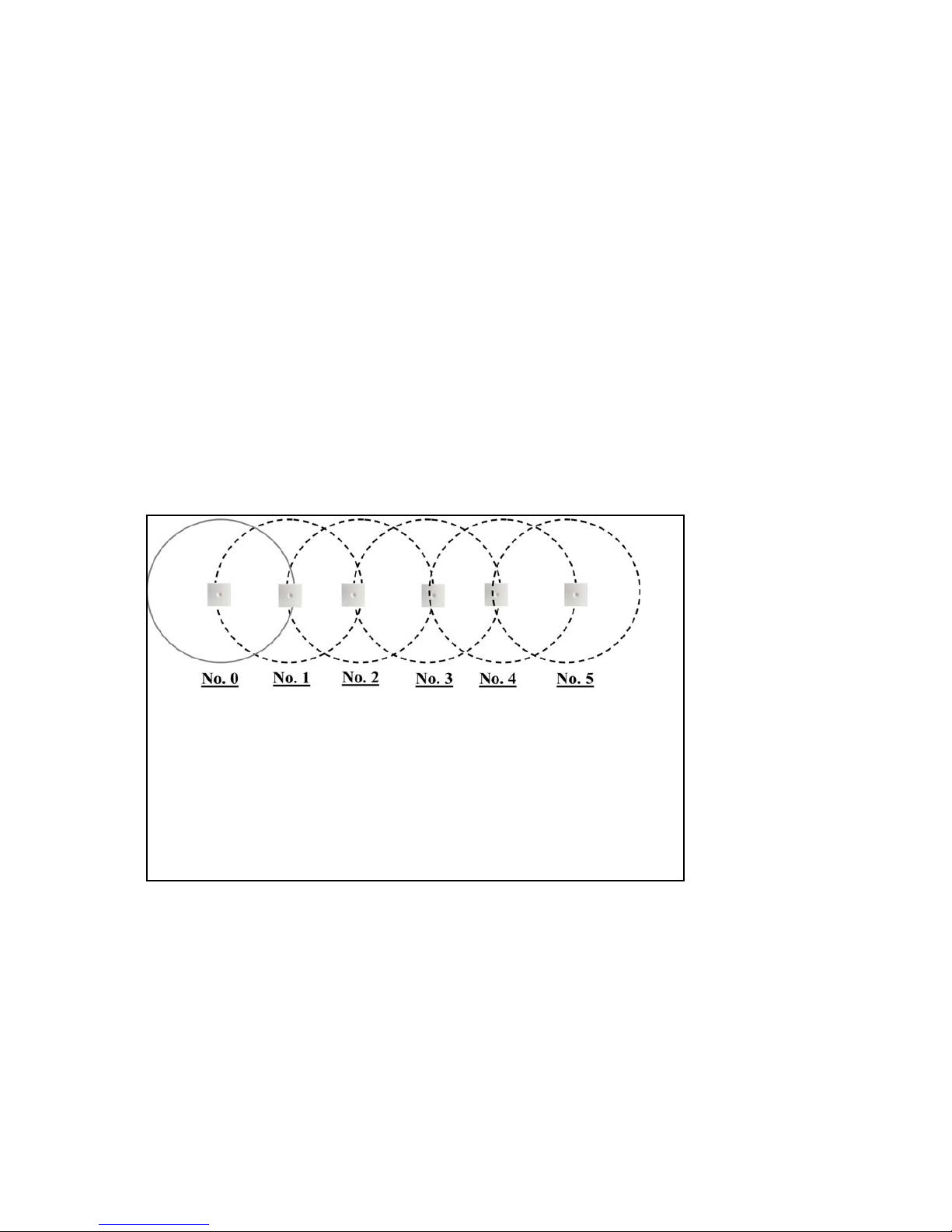
Sync Chain With One Sync Master (Primary Sync Ways)
Figure 25 Synchronization Chain
• The synchronization chain must always overlap with the base station
to sync on.
• No.0 is the Sync Master (can be numbered 0-255).
• Other radio units are connected to the Sync Master through the
synchronization chain.
• If one of the radio units in the synchronization chain is not working,
then the synchronization chain is broken and the system will be
unstable.
Page 53

Spectralink IP-DECT Server 6500 Installation and Configuration Guide
14215700 Version 3.0
April, 2014 51
Figure 26 Synchronization Chain Layout without Alternative Sync Ways
Sync Chain With Alternative Sync Ways
Figure 27 Synchronization Chain with Alternative Sync Ways
• No. 0 is the Sync Master (can be numbered 0-255).
• It is recommended to place the Sync Master in the middle of the
building.
• Green line: Shows the primary sync ways.
• Brown line: Only handover overlap is needed.
• It is recommended to make a site planner. Every base station must be
numbered with Radio ID, Primary sync Radio ID, and Alternative
sync Radio ID.
• No. 0 is the
Sync Master (can be numbered 0-255).
• No. 10 and No. 20: Primary and alternative sync on No. 0.
• No. 11: Primary sync on No. 10 and alternative sync on No. 21.
• No. 21: Primary sync on No. 20 and alternative sync on No. 11.
Page 54

Spectralink IP-DECT Server 6500 Installation and Configuration Guide
14215700 Version 3.0
April, 2014 52
In the following example, base station No. 10 is down. As a consequence, base station No. 11
must use the alternative sync way on No. 21.
Figure 28 Synchronization Chain with Alternative Sync Ways
Figure 29 Synchronization Chain with Alternative Sync Ways
• No. 0 is the Sync Master (can be numbered 0-255).
• No. 10 and No. 20: Primary and alternative sync on No. 0.
• No. 11: Primary sync on No. 10 and alternative sync on No. 21.
• No. 21: Primary sync on No. 20 and alternative sync on No. 11.
• No. 0 is the Sync Master (can be numbered 0-255).
• No. 10, No. 20, No. 30, and No. 40: Primary and alternative sync
on No. 0.
• No. 11: Primary sync on No. 10 and alternative sync on No. 21.
• No. 21: Primary sync on No. 20 and alternative sync on No. 11.
• No. 31: Primary sync on No. 30 and alternative sync on No. 41.
• No. 41: Primary sync on No. 40 and alternative sync on No. 31.
Page 55

Spectralink IP-DECT Server 6500 Installation and Configuration Guide
14215700 Version 3.0
April, 2014 53
Figure 30 Synchronization Chain Layout with Alternative Sync Ways
• No. 0 is the Sync Master (can be numbered 0-255).
• It is recommended to place the Sync Master in the middle of the
building.
• Green line: Shows the primary sync ways.
• Red line: Shows the alternative sync ways.
• It is recommended to make a site planner. Every base station must
be numbered with Radio ID, Primary sync Radio ID, and
Alternative sync Radio ID.
Page 56
Spectralink IP-DECT Server 6500 Installation and Configuration Guide
14215700 Version 3.0
April, 2014 54
Sync Chain With and Without Alternative Sync Ways
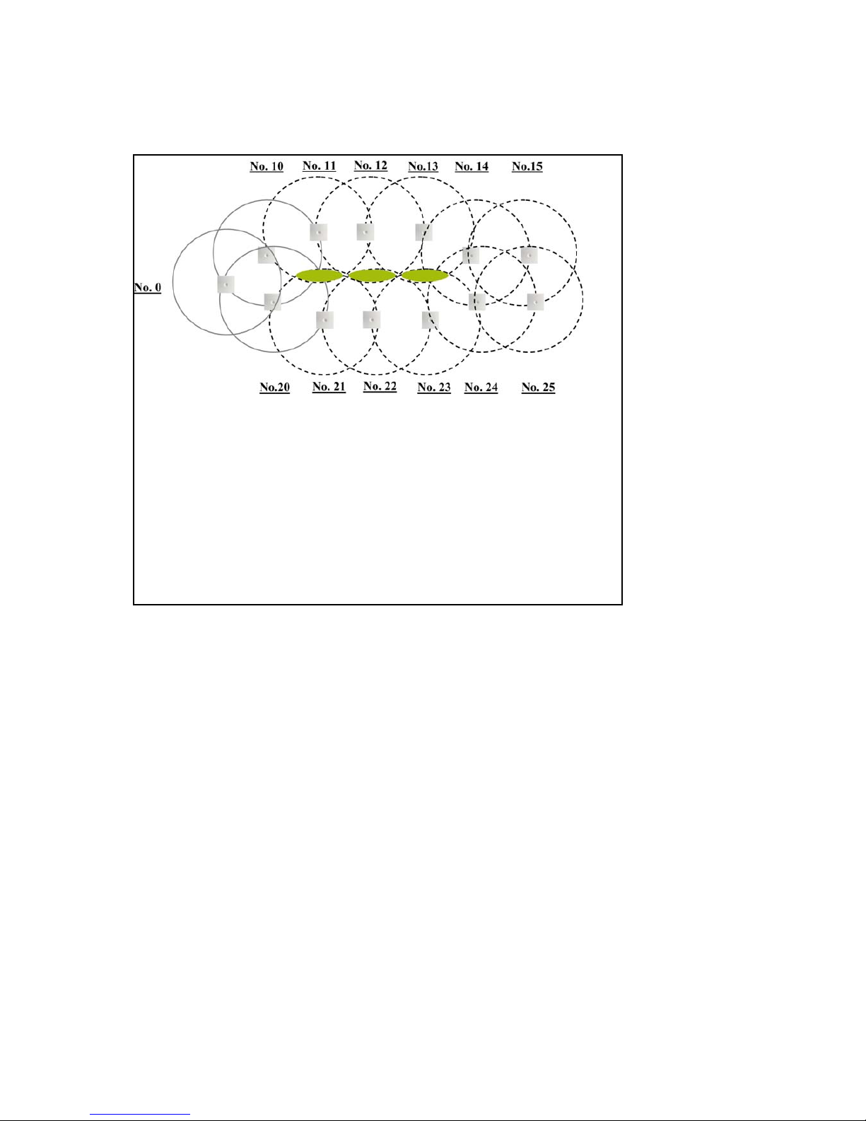
Figure 31 Synchronization Chain With and Without Alternative Sync Ways
• No. 0 is the
Sync Master (can be numbered 0-255).
• No. 10 and No. 20: Primary and alternative sync on No. 0.
• No. 11, No. 12 and No. 13: Only primary sync.
• No. 14 and No. 15: Primary sync and alternative sync.
• No. 21, No. 22 and No. 23: Only primary sync.
• No. 41: Primary sync on No. 40 and alternative sync on No. 31.
• No. 11 and No. 21: Only handover overlap (Marked with green).
Page 57

Spectralink IP-DECT Server 6500 Installation and Configuration Guide
14215700 Version 3.0
April, 2014 55
Figure 32 Synchronization Chain With Repeaters
• No. 0 is the
Sync Master (can be numbered 0-255).
• No. 10 and No. 20: Primary and alternative sync on No. 0.
• No. 74, No. 138 and No. 202: Repeater - no alternative sync
possible.
• No. 14 and No. 15: Primary sync and alternative sync on repeater.
• No. 84, No. 148 and No. 212: Repeater - no alternative sync
possible.
• No. 24 and No. 25: Primary sync and alternative sync.
• No. 74 and No. 84: Only handover overlap (Marked with green).
Page 58

Spectralink IP-DECT Server 6500 Installation and Configuration Guide
14215700 Version 3.0
April, 2014 56
Chapter 8: Configuring Spectralink Media
Resources
This section provides you with information on how to power up the media resource and connect
the unit to a computer. It also provides information on how to configure a media resource through
the web based Administration Page using either DHCP or static IP address.
Configuring a Spectralink Media Resource Using Static
IP Address
General Configuration
On the Configuration/General page you define IP, DNS and NTP settings for the media resource.
Media Resource Configuration
On the Configuration/Media Resource page you configure the media resource.
1 Click Configuration, and then click Media Resource.
Figure 33 Adm. Page Media Resource: Config./Media Resource page
2 In the Host field, type the address of the wireless server.
3 Click Save.
Note
The media resource is pre-configured to use DHCP. It is recommended to configure the media
resource using DHCP.
Page 59

Spectralink IP-DECT Server 6500 Installation and Configuration Guide
14215700 Version 3.0
April, 2014 57
Checking Indicators
• Verify that the media resource LED indicator is continuously on, indicating that the media
resource is functional.
Note
The LED will not turn on until the base stations are configured.
Page 60

Spectralink IP-DECT Server 6500 Installation and Configuration Guide
14215700 Version 3.0
April, 2014 58
Chapter 9: Configuring Spectralink IP-DECT
Base Station
This section provides you with information on how to connect the base station to a Spectralink
IP-DECT Server 6500 and how to configure the base station through the web based
Administration Page using either DHCP or static IP address.
Powering up the Spectralink Base Station
After installing the base station you need to power it up. The base station uses:
• Power over Ethernet (PoE 802.3af).
• Maximum power supply consumption is 3.0W (IEEE 802.3af class 1 device).
Use a standard PoE adapter or a PoE-enabled port on a switch adhering to PoE 802.3af when
connecting the base station to a PoE power source.
Use an 8V-DC power supply when using a power supply as power source.
Accessing the Web Based Administration page of the
Base Station
The Spectralink IP Base station can only communicate with the network trough a patch cable
connected to a 10/100-Mbit/s Switch port.
Note
The base station is pre-configured to use DHCP. It is strongly recommended that you configure
the base station using DHCP. When using DHCP the IP base station should be discovered by
UPnP
Note
The LAN port of the base station is a RJ45 connector.
Page 61
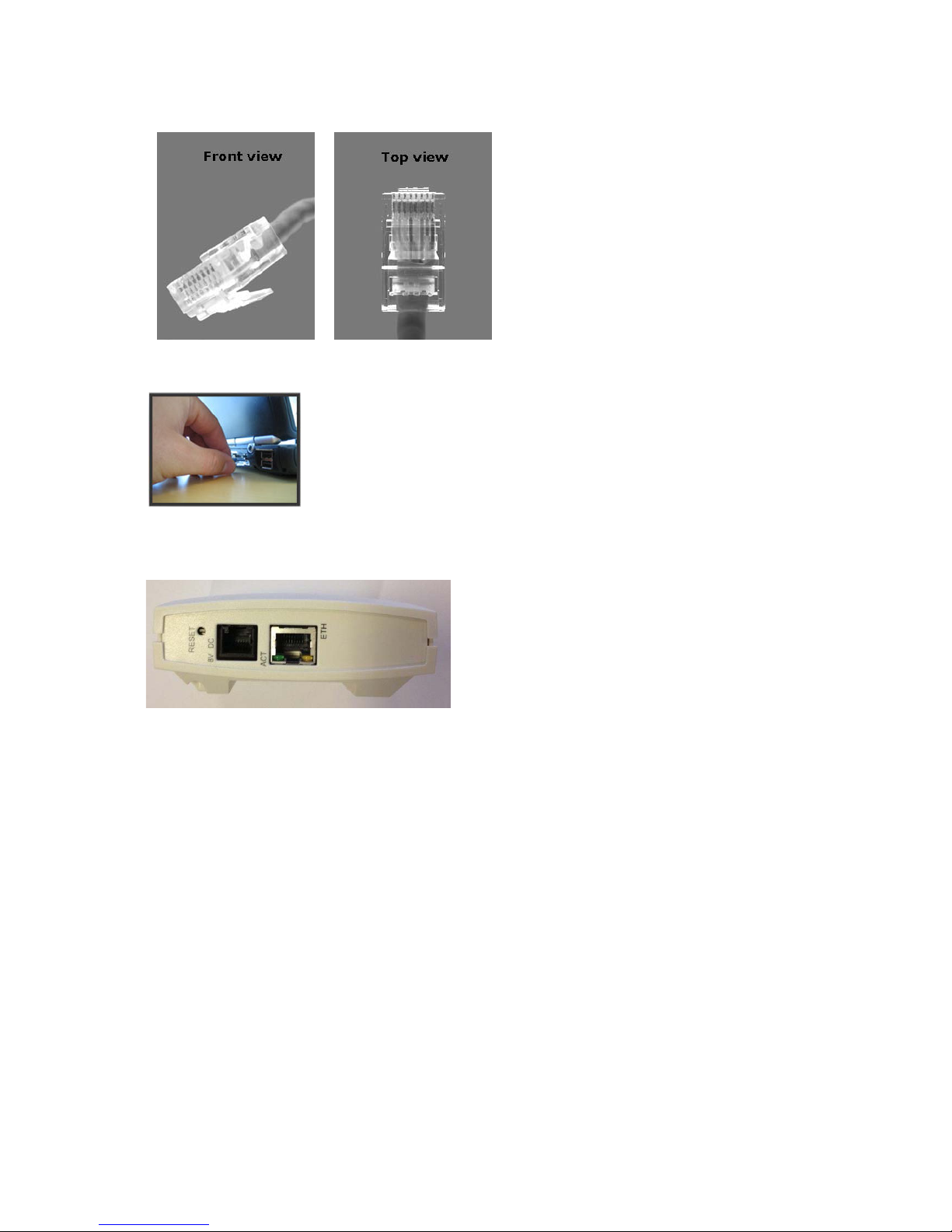
Spectralink IP-DECT Server 6500 Installation and Configuration Guide
14215700 Version 3.0
April, 2014 59
Figure 34 Cross-Over Patch Cable (RJ45)
1 Connect the LAN cable or cross-over patch cable to the computer.
2 Connect the LAN patch cable to the ethernet connector at the bottom of the base station.
Figure 35
Accessing the Web Based Administration Page
The web based Administration Page is accessed through a standard web browser.
1 Open a web browser.
2 In the browsers Address bar, type http://192.168.0.1 or the IP address discovered by UPnP,
and then click ENTER.
Page 62
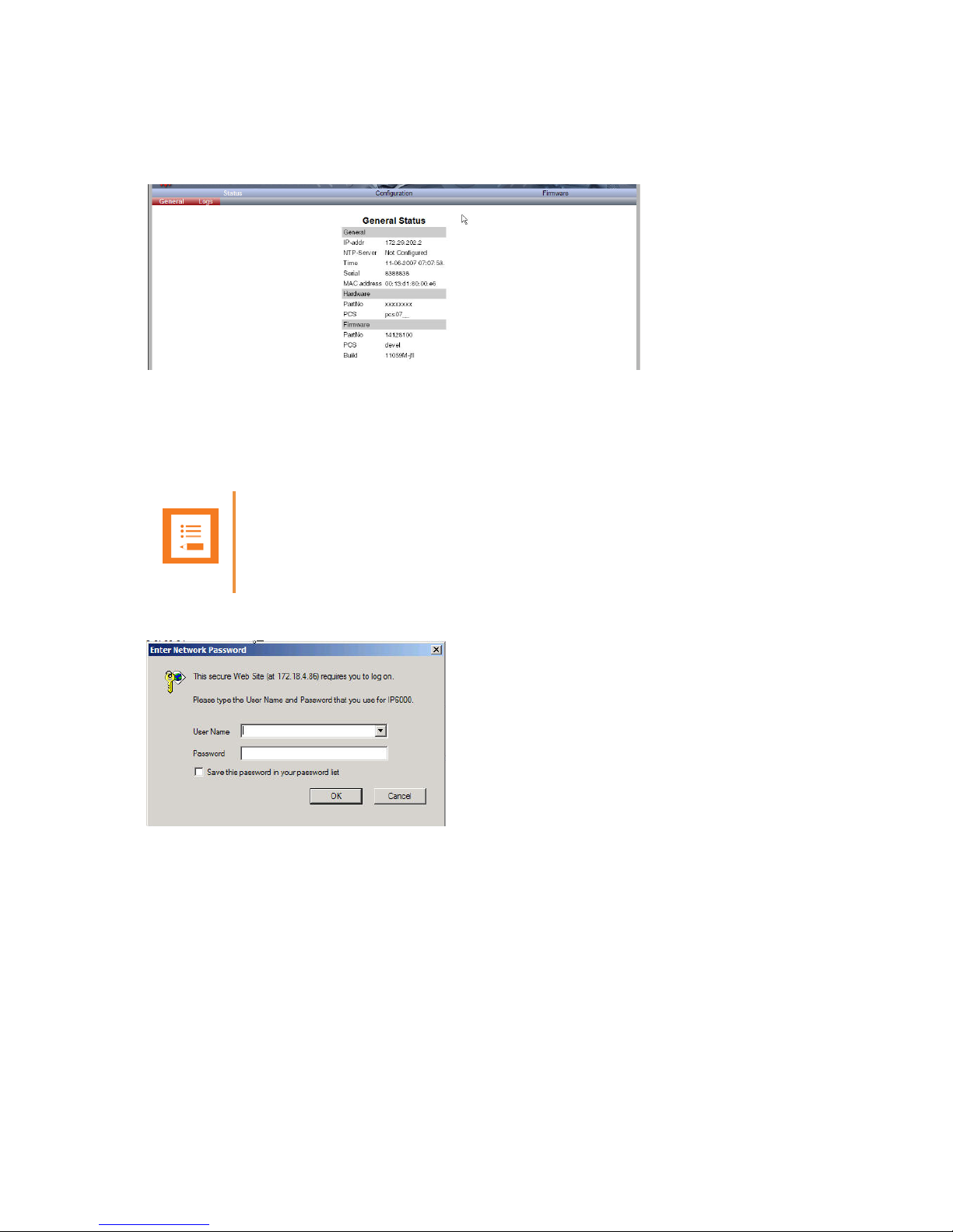
Spectralink IP-DECT Server 6500 Installation and Configuration Guide
14215700 Version 3.0
April, 2014 60
Note: If no DHCP server is available, the base station will fall back to IP address 192.168.0.1. This
happens one minute after startup.
Figure 36 Main page of the Administration Page for base station
Entering a System User Name and Password
The first time you access the Administration Page, you need to log on with user name and a
password.
Figure 37 Adm. Page: Enter Network Password dialog box
1 In the User Name field, type admin.
2 In the Password field, type ip6000.
3 Click OK.
Configuring a Spectralink Base Station
This section describes how to configure a base station.
Note
The default user name of the system is admin and the default password of the system is
ip6000. It is strongly recommended that you change the password.
Page 63

Spectralink IP-DECT Server 6500 Installation and Configuration Guide
14215700 Version 3.0
April, 2014 61
If the Spectralink IP-DECT Server 6500 is configured using a static IP address, it is possible to
assign options to the DHCP server making it extremely easy to configure all base stations.
General Configuration
On the General Configuration page you define IP, DNS, and NTP settings for the base station.
1 Click Configuration, and then click General.
Figure 38 Adm. Page Base Station: Configuration/General page
2 Click DHCP assigned.
3 Apply the desired values as described in the following table.
Note
t is strongly recommended that the base station is configured using DHCP. The base station
is pre-configured to use DHCP.
Field
Explanation
RequiredOptiona
l
General Configuration - IP
Use Static
IP Address
Enable the field if you want to use a static IP
address.
x
IP Addr
Enter the IP address of the KWS 6500 x
Netmask
Enter a new network mask. Contact you
system administrator for more information.
x
Gateway
Enter the IP address of the default gateway.
The default gateway serves as an access
point to another network. Contact your
system administrator for more information.
x
Page 64

Spectralink IP-DECT Server 6500 Installation and Configuration Guide
14215700 Version 3.0
April, 2014 62
Field
Explanation
RequiredOptiona
l
MTU
(Maximum
Translation
Unit)
Enter the size of the largest packet, that
your network protocol can transmit
x
VLAN
Enter the VLAN Identifier (VID) according to
IEEE 802.1Q specifying the VLAN to which
the device belongs. The IP-DECT Server
400 supports 4094 different VLANs.
Values: 1-4094
x
General Configuration - DNS (Domain Name System)
Hostname
The hostname will be inserted into the SIP
Contact and via headers. The hostname will
also be published via DHCP and if the
network infrastructure supports it, the
device will be reachable via this hostname.
x
Domain
Enter the name of the domain where
system belongs.
x
Primary
Server
Enter the IP address of the Primary DNS
server
x
Secondary
Server
Enter the IP address of the Secondary DNS
server
x
General Configuration - NTP (Network Time Protocol)
Server
Enter the address of the NTP server from
which the system will obtain the current
time.
x
Time Zone
Select the time zone. x
UPnP
Enabled
UPnP is an acronym for Universal Plug and
Play. If the IP-address of the device is
unknown (e.g. forgotten or
DHCP-assigned), UPnP can be used to
easily identify the IP-address of the device.
If “My Network Places” in Windows is setup
to show icons for networked UPnP devices,
every KWS 6500, Media resource and Base
station will be present in “My Network
Places”.
Enabled
by
default
Page 65

Spectralink IP-DECT Server 6500 Installation and Configuration Guide
14215700 Version 3.0
April, 2014 63
Security Configuration
It is possible to change the password for the unit.
1 Click Configuration, and then click Security (optional).
Figure 39 Adm. Page Base Station: Configuration/Security page
2 In the Current password field, type the current password.
3 In the New username field, type a new username.
4 In the New password field, type a password.
5 In the New password again, type the password again.
6 Click Allow remote logging if it should be possible to log on to the system remotely (Useful
in case of troubleshooting).
7 Click Save.
Base Station Configuration
To configure the base station:
1 Click Configuration, and then click Base Station.
Broadcast
announcem
ents
Specifies if UPnP announcements are
broadcasted. When enabled, the device
broadcasts announcements automatically.
x
Host
Port
Facility
Level
Page 66
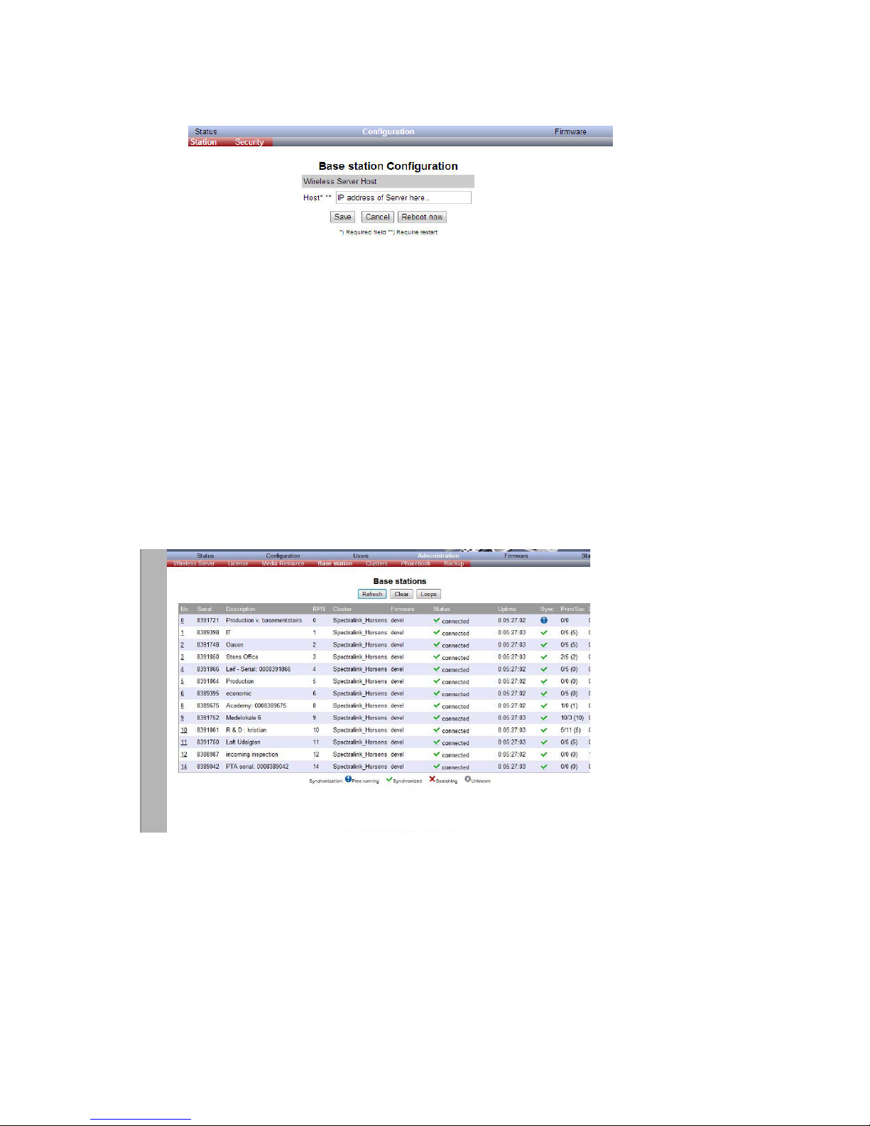
Spectralink IP-DECT Server 6500 Installation and Configuration Guide
14215700 Version 3.0
April, 2014 64
Figure 40 Configuration/Base Station
2 In the Host field, type the host name of the IP-DECT Server 6500.
3 Click Save.
4 Click Reboot to enable the configuration changes.
Sync. Ways Configuration
It is necessary to define the synchronization ways of the base station.
1 To define the sync. ways of the base station, open the Administration Page for the
Spectralink IP-DECT Server 6500.
2 Click Administration, Server, and then click Base Station.
Figure 41 Adm. Page WS:Administration/Base station page
3 Double-click on the relevant base station in the list.
Page 67

Spectralink IP-DECT Server 6500 Installation and Configuration Guide
14215700 Version 3.0
April, 2014 65
Figure 42 Adm. Page WS:Administration/Base station page
4 In the RPN field (Radio Part Number), type the radio part number of the base station.
The radio ID can be a number between 0 and 255. See your site planner.
Note: The default value of the RPN is equal to the base station number. It is strongly recommended not
to change this value.
5 It is possible to select Auto sync if you are deploying and want to find a sync way for the first
base station.
Note: Auto sync is only to be used in a deployment situation. When selecting Auto sync, radio part
numbers in the Primary sync. (RPN) field and Secondary sync. (RPN) field are not taken into
consideration.
6 In the Primary sync. (RPN) field, type the radio part number of the base station, you want to
synchronize on. See your site planner.
7 In the Secondary sync. (RPN) field, type the radio part number of the base station, you want
to synchronize on. See your site planner.
8 Click Save. The base station will reboot automatically and reconnect to the server.
Checking Indicators
• Verify that the base station LED indicator is continuously on, indicating that the base station is
functional.
Page 68

Spectralink IP-DECT Server 6500 Installation and Configuration Guide
14215700 Version 3.0
April, 2014 66
Chapter 10: Spectralink Handset
Registration
This section provides information about handset registration. You must register and subscribe a
handset before you can use it.
When registering handsets you enter information about the handsets settings (such as; the
handsets serial number (IPEI), name etc.) in the system database. When subscribing handsets
you subscribe a registered handset to the system for usage. If the handset is not registered in the
system database, subscription of the handset is not possible.
Registering Spectralink Handsets
To register handsets you use the web based Administration Page of the Spectralink IP-DECT
Server 6500.
Each handset in the wireless solution must be programmed with the serial number (IPEI) before
it can operate. This serial number must be registered in the web based Administration Page of the
Spectralink IP-DECT Server 6500. Serial numbers are a unique fingerprint of each handset. The
serial number is programmed into the handset during the manufacturing process and cannot be
changed by field personnel.
1 Click Users and then click List Users.
Note
This section only describes how to register handsets on the Spectralink IP-DECT Server 6500.
You also need to register the users on the call handler. For registering users on the call
handler, refer to the call handler user guide.
Note
The Spectralink IP-DECT Server 6500 does not provide any service to a handset whose
serial number is not registered on the web based Administration Page.
Page 69

Spectralink IP-DECT Server 6500 Installation and Configuration Guide
14215700 Version 3.0
April, 2014 67
Figure 43 Adm. Page WS: Users/List Users page
2 Click New.
Figure 44 Adm. Page WS: Users/List Users/Users page
The data configured for each handset can be split into two categories. DECT data which is
necessary for the correct handling of the DECT protocol stack. SIP data which is necessary
for the handling of a SIP user agent.
3 In the IPEI field, type the IPEI number (serial number) of the handset. The serial number
consists of a five-digit handset type (manufacturer code) and a seven-digit handset number.
4 In the Access code field, type the authentication code (AC) (optional)
The authentication code is a subscription password of a maximum of eight digits, defined by
the technicians, and can be used when connecting the handset to a Spectralink IP-DECT
Server 6500. The authentication code is a subscription pin code for the individual handset.
5 In the Standby text field, type a text to be displayed when the handset is on hook (optional).
6 In the Username/Extension field, type the user part of a SIP URI, e.g., 1234 in John
Doe<sip:1234@somecompany.com>.
7 In the Domain field, type the domain part of a SIP URI, e.g. somecompany.com in John
Doe<sip:1234@somecompany.com> (optional).
Note: If not configured, the default domain entered under SIP configuration will be used.
8 In the Displayname field, type the name to be displayed (caller ID), e.g. John Doe in John
Doe<sip:1234@somecompany.com> (optional).
Page 70

Spectralink IP-DECT Server 6500 Installation and Configuration Guide
14215700 Version 3.0
April, 2014 68
9 In the Authentication user field, type a user name (optional).
10 The user name will override the Default User field under SIP Configuration.
11 In the Authentication password field, type a password (optional).
The password will override the Default Password field under SIP Configuration.
12 Click Save to save the registration(s).
Retrieving the IPEI Number of the Spectralink Handset
To enable service to the handset, the IPEI number must be programmed into the system database
via the web based Administration Page of the Spectralink IP-DECT Server 6500.
The IPEI number of each handset is found either on a label, which is placed behind the battery, or
on the packaging label.
To show the serial number on the handset display (40-Handsets), press *99984*, and then press
; the serial number appears on the handset display. Press < for 5 seconds to exit the menu.
To show the serial number on the handset display (50/60/70/Butterfly Handset), press Menu,
select Status and then select General information to display the IPEI number. Press exit to exit the
menu.
Page 71
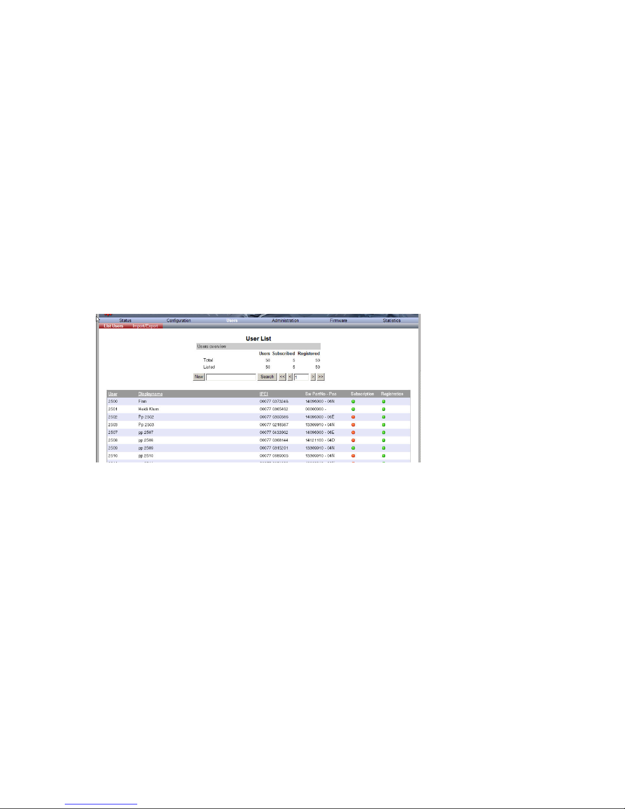
Spectralink IP-DECT Server 6500 Installation and Configuration Guide
14215700 Version 3.0
April, 2014 69
Chapter 11: Spectralink Handset
Management
This section provides information about handset management such as viewing handset
configuration, deregistering handsets and changing user configurations using the web based
Administration Page. It also provides information about unsubscribing handsets,
exporting/restoring/importing handset registration data and handset adjustment.
Viewing Handset/User Configuration
Through the web based Administration Page, it is possible to view all the user configurations of
the wireless system.
1 Click Users, and then click List Users.
Figure 45 Adm. Page WS: Users/List Users page
Searching for Handset/User Information
Through the web based Administration Page, it is possible to search for a registered handset/user
in the system.
1 Click Users, and then click List Users.
Page 72

Spectralink IP-DECT Server 6500 Installation and Configuration Guide
14215700 Version 3.0
April, 2014 70
Figure 46 Adm. Page WS: Users/List Users page
2 Type the beginning of a user, display name or IPEI to search for in the text field, and then
click Search.
Unsubscribing Spectralink Handsets
Spectralink 40-Handset
To unsubscribe a handset:
1 Press MENU ().
2 Press < - go to MENU LOGIN.
3 Press .
4 Press < - go to SUBSCRIPTION REMOVE.
5 Press .
6 Enter password (0000).
7 Press .
8 If handset is subscribed to more than one system, select the system ARI in question.
The handset has been unsubscribed.
Note
Removing a subscription requires a password. The default password is: 0000.
Page 73

Spectralink IP-DECT Server 6500 Installation and Configuration Guide
14215700 Version 3.0
April, 2014 71
Spectralink 50/60/70/Butterfly Handset
To remove a Login:
Logins can be removed from the system in use and from the 15 other systems (if connected).
1 Press Menu to enter main menu.
2 Scroll to Settings and press Select.
3 Scroll to Advanced and press Select.
4 Scroll to Login and press Select.
5 Scroll to Remove login and press Select.
6 Scroll to the desired login and press Select.
7 Enter your password and press Ok.
Removing Spectralink Handsets from the List
(Deregistering)
You can deregister handsets from Spectralink IP-DECT Server 6500. This is necessary when:
• you must replace the handset due to loss or breakage.
• you want to assign the handset to a user with a different telephone number.
1 Click Users, and then click List Users.
Note
Removing a login requires a password. The default password is: 0000.
Note
If the system in use is removed, it is necessary to select one of the remaining systems or to
subscribe to a new one.
Note
If one of the systems not chosen is removed, the handset remains connected to the system in
use.
Page 74

Spectralink IP-DECT Server 6500 Installation and Configuration Guide
14215700 Version 3.0
April, 2014 72
Figure 47 Adm. Page WS: Users/List Users page
2 Type the beginning of a number or name to search for in the text field, and then click Search
or select the handset in question by clicking on the user information.
The following page appears.
Figure 48 Adm. Page WS: Users/List Users/User page
3 Click Delete to remove the registration.
A warning box appears.
Figure 49 Warning box
4 Click OK.
Changing User Configurations
You can change user configurations, such as the AC (authentication code) using the web based
Administration Page.
Page 75

Spectralink IP-DECT Server 6500 Installation and Configuration Guide
14215700 Version 3.0
April, 2014 73
1 Click Users, and then click List Users.
Figure 50 Adm. Page WS: Users/List Users page
2 Type the beginning of a number or name to search for in the text field, and then click Search
or select the handset in question by clicking on the user information.
The following page appears.
Figure 51 Adm. Page WS: Users/List Users/User page
3 Change settings, and then click Save.
Exporting Handset Registration Data
You can export handset registration data using the web based Administration Page. It is possible
to export a user database with subscriptions and to export a user database separately from
subscriptions (configuration data only).
1 Click Users, and then click Import/Export.
Page 76

Spectralink IP-DECT Server 6500 Installation and Configuration Guide
14215700 Version 3.0
April, 2014 74
Figure 52 Adm. Page WS: Users/Import/Export page
2 Under Backup User Data do one of the following:
a To save configuration data, click the Save button after User database.
b To save user data with subscriptions, click the Save button after Subscriptions.
A File Download dialog box appears.
Figure 53 Adm. Page: File Download dialog box.
3 Click Save.
A Save As dialog box appears.
Page 77
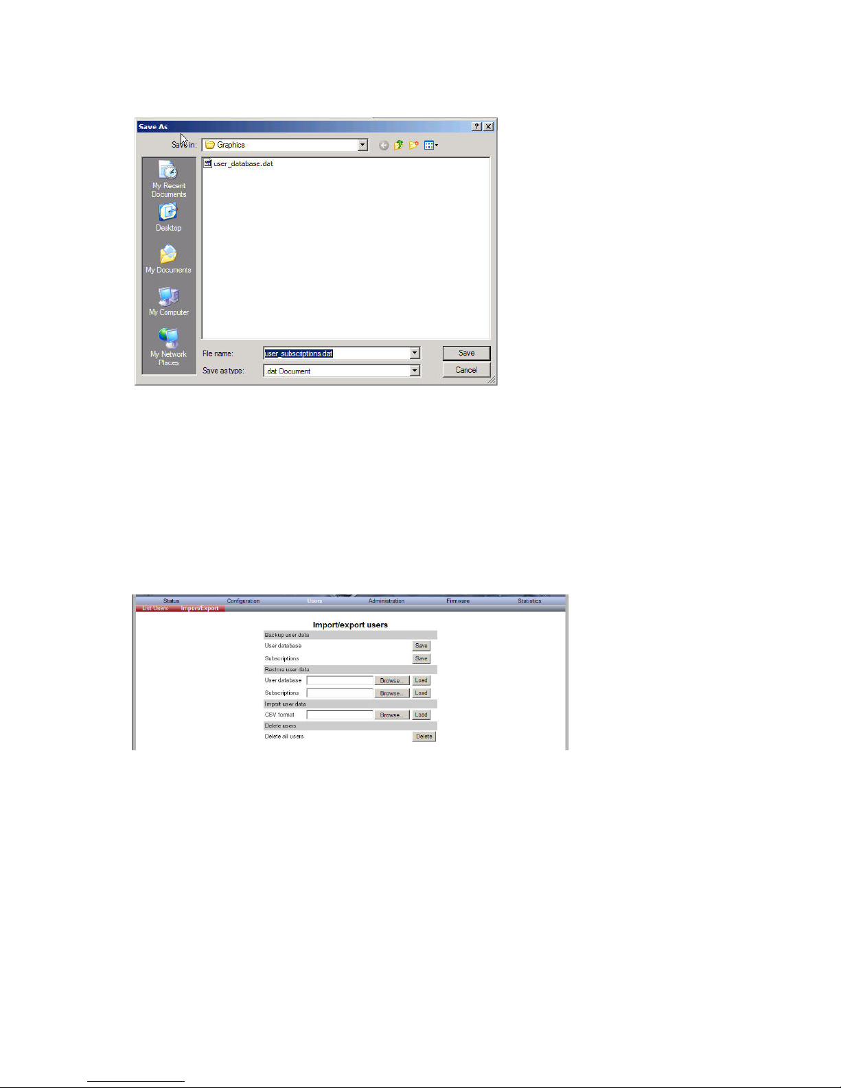
Spectralink IP-DECT Server 6500 Installation and Configuration Guide
14215700 Version 3.0
April, 2014 75
Figure 54 Adm. Page: Save As dialog box
4 Indicate in which folder and under what name the file should be saved, and then click Save.
Restoring Handset Registration Data
You can restore handset registration data using the web based Administration Page. It is possible
to restore a user database with subscriptions and to restore a user database separately from
subscriptions (configuration data only).
1 Click Users, and then click Import/Export.
Figure 55 Adm. Page WS: Users/Import/Export page
2 Under Restore User Data do one of the following:
a To restore configuration data, click the Browse button after User database.
b To restore user data with subscriptions, click the Browse button after Subscriptions.
A Choose File dialog box appears.
Page 78
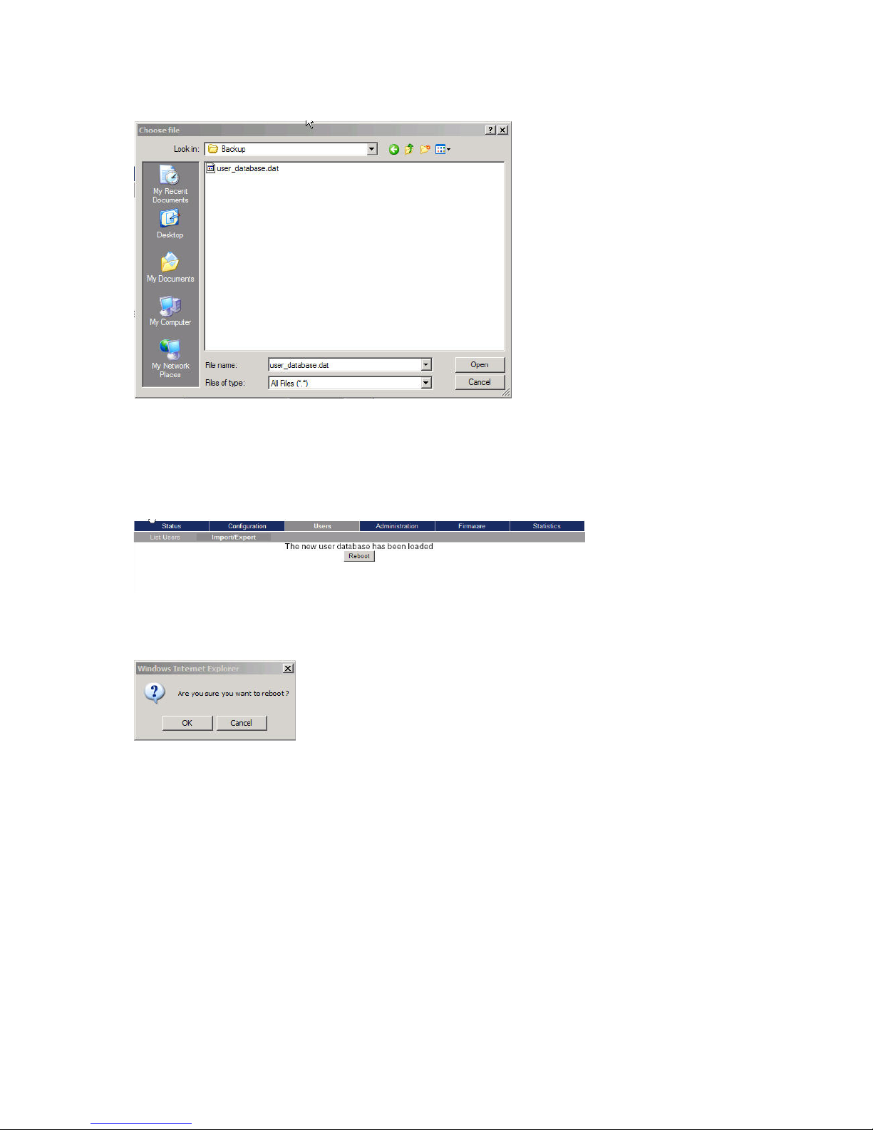
Spectralink IP-DECT Server 6500 Installation and Configuration Guide
14215700 Version 3.0
April, 2014 76
Figure 56 Adm. Page: Choose File dialog box
3 Select the file in question, and then click Open.
4 Click Load.
The following page appears.
Figure 57 Adm. Page WS: Users/Import/Export/Loaded page
5 Click Reboot. A warning message appears.
Figure 58 Adm. Page: Reboot Warning message
6 Click OK.
The system is rebooted. This can take a few minutes.
Importing Handset Registration Data - CSV Format
You can import handset registration data in CSV format. To be able to import the data correctly,
you must create a file containing the following information and punctuation:
#IPEI,access code,standby text,username,domain,displayname,authenticate
user,authenticate password,local number
Page 79

Spectralink IP-DECT Server 6500 Installation and Configuration Guide
14215700 Version 3.0
April, 2014 77
Figure 59 Example of Handset Registration Data in CSV Format
1 Click Users, and then click Import/Export.
Figure 60 Adm. Page WS: Users/Import/Export page
2 Under Import User Data, click Browse to find the CSV file with handset registration data.
A Choose File dialog box appears.
Figure 61 Adm. Page: Choose File dialog box
3 Select the file in question, and then click Open.
Note
If you want to leave out some of the information, e.g. standby text, you must keep the
commas, e.g.:#IPEI,access code,,username,domain,displayname,authenticate
user,authenticate password,local number.
Page 80

Spectralink IP-DECT Server 6500 Installation and Configuration Guide
14215700 Version 3.0
April, 2014 78
4 Click Load.
5 Click OK.
Note
It is not possible to import handset registration data already registered in the system.
Page 81
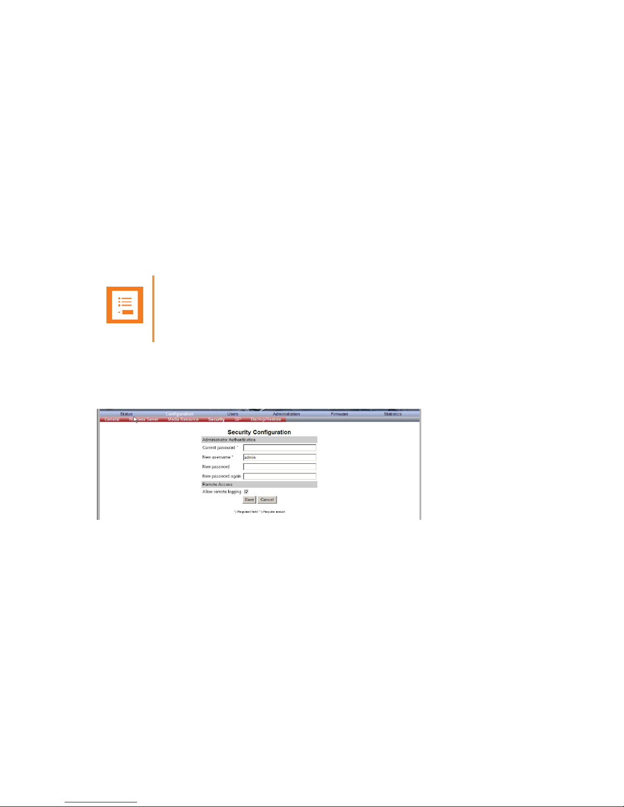
Spectralink IP-DECT Server 6500 Installation and Configuration Guide
14215700 Version 3.0
April, 2014 79
Chapter 12: System Management
This section provides you with information about the web based Administration Page of the
Spectralink IP-DECT Server 6500.
Through the web based Administration Page of the Spectralink IP-DECT Server 6500 it is possible
to define and view different settings of the system, reading statistics, making a backup of
configuration file, updating system software, and resetting the system.
Spectralink IP-DECT Server 6500
Changing System User Name and Password
From the Administration Page it is possible to change the user name and password for the system.
1 Click Configuration, and then click Security.
Figure 62 Adm. Page WS: Configuration/Security page
2 In the Current password field, type the current password.
3 In the New user name field, type a user name.
4 In the New password field, type a new password
5 In the New password again field, type the new password again to confirm it.
6 Click Save to change the password.
Note
It is not possible to import handset registration data already registered in the system.
Page 82

Spectralink IP-DECT Server 6500 Installation and Configuration Guide
14215700 Version 3.0
April, 2014 80
Reading System Information
Under Status it is possible to get general information about hardware version, firmware and
message logging. This information is useful in case of problem solving. Accessing the
Administration Page of the wireless server provides an overview of the solution.
General Status Information
This page provides general system information such as hardware, firmware and OS Status
information.
1 Click Status, and then click General.
Figure 63 Adm. Page Wireless Server: Status/General page
On the Status/General page the following information is available.
— General
— IP-address: current IP address of device
— NTP-Server: address of time server
— Time: current time on device
— Serial: Serial number of device
— MAC address: of device
— Product ID: from device
— Production Date: of device
— Hardware
— PartNoof hardware
— PCSHardware version of device_
— Firmware
— PartNosoftware part number
— PCSSoftware version
— BuildSoftware build number
—
— Quick status Red/Green/Grey
Page 83

Spectralink IP-DECT Server 6500 Installation and Configuration Guide
14215700 Version 3.0
April, 2014 81
— SIPQuick status
— Base stationsQuick status
— Media resources Quick status
— ProvisioningQuick status
— NTPQuick status
Logs Information
This page provides log information such as media resource connection, base station connection
and different types of status.
1 Click Status, and then click Logs.
Figure 64 Adm. Page WS: Status/Logs page
2 From the Display filter list you can select between emergency, critical, error, warning,
notice or info depending on the logs you want to see.
The different types of status are:
— emergency (errors causing the system to malfunction for all calls)
— critical (events that do not occur under normal operation, cause minor malfunction)
— error (events that do not occur under normal operation, cause minor malfunction)
— warning (events that do not occur under normal operation, may cause malfunction)
— notice info (events that occur under normal operation, relevant to an
3 Click Save if you want to save the logs in a file.
A Save As dialog box appears.
Page 84
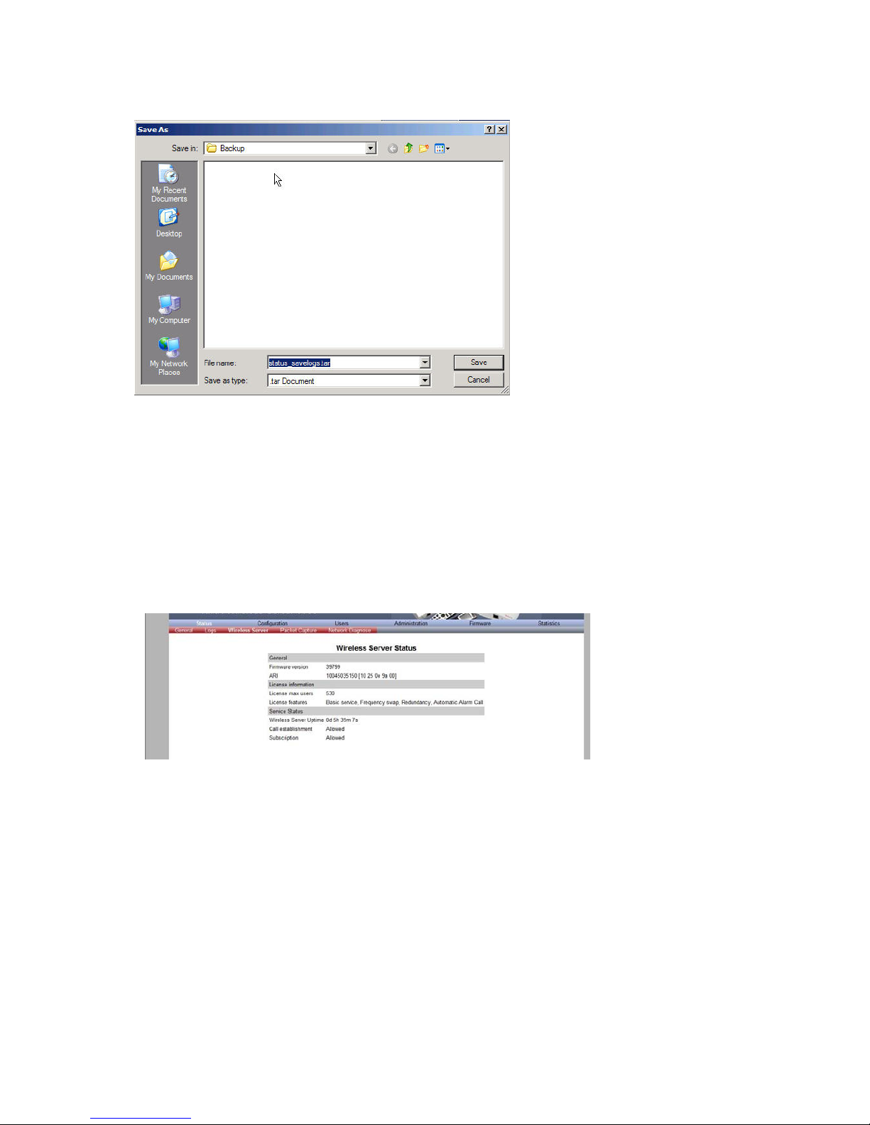
Spectralink IP-DECT Server 6500 Installation and Configuration Guide
14215700 Version 3.0
April, 2014 82
Figure 65 Adm. Page: Save As dialog box
4 Indicate in which folder and under what name the file should be saved, and then click Save.
It is now possible to send the log files to authorized technicians for further support and problem
solving.
Wireless Server Information
This page provides information about the firmware version and ARI code of the Spectralink
IP-DECT Server 6500.
1 Click Status, and then click Wireless Server.
Figure 66 Adm. Page Wireless Server: Status/Wireless Server page
Reading Statistics
Under Statistics, it is possible to read statistic information about the Spectralink IP-DECT Server
6500, media resource, base station, and calls, handovers and abnormal releases in the system.
You get an over all overview of how the system is running.
Page 85
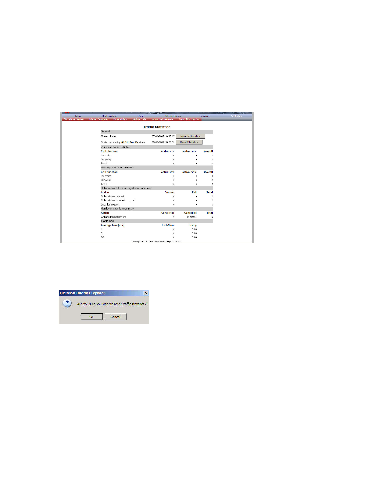
Spectralink IP-DECT Server 6500 Installation and Configuration Guide
14215700 Version 3.0
April, 2014 83
Wireless Server
This page is useful to get information about traffic on the Spectralink IP-DECT Server 6500 such
as voice call traffic and message call traffic and it provides a summary of subscription and
handover statistics. It also provides information about the traffic load (Erlang) of the installation
which is useful when determining the number of media resources needed.
1 Click Statistics, and then click Wireless Server.
Figure 67 Adm. Page Wireless Server: Statistics/Wireless Server page
2 Click Reset Statistics if you want to delete all statistic traffic information.
A warning message appears.
Figure 68 Warning message
3 Click OK.
Media Resource
This page is useful to get information about the media resource.
1 Click Statistics, and then click Media Resource.
Page 86

Spectralink IP-DECT Server 6500 Installation and Configuration Guide
14215700 Version 3.0
April, 2014 84
Figure 69 Adm. Page Wireless Server: Statistics/Media Resource page
Base Station
This page is useful to get statistic information about the base station.
1 Click Statistics, and then click Base Station.
Figure 70 Adm. Page Wireless Server: Statistics/Base Station page
Active Calls
This page is useful to get statistic information about active calls in the Spectralink IP-DECT Server
6500 installation.
1 Click Statistics, and then click Active Calls.
Figure 71 Adm. Page Wireless Server: Statistics/Active Calls page
Abnormal Releases
This page is useful to get statistic information about abnormal releases in a Spectralink IP-DECT
Server 6500 installation.
1 Click Statistics, and then click Abnormal Releases.
Page 87

Spectralink IP-DECT Server 6500 Installation and Configuration Guide
14215700 Version 3.0
April, 2014 85
Figure 72 Adm. Page Wireless Server: Statistics/Abnormal Releases page
Traffic Distribution
This page is useful to get statistic information about traffic distribution during the last 24 hours in
a Spectralink IP-DECT Server 6500 installation.
1 Click Statistics, and then click Traffic Distribution.
Figure 73 Adm. Page Wireless Server: Statistics/Traffic Distribution page
Making a Back-Up of the Configuration File
This section provides information about saving the configuration data of the Spectralink IP-DECT
Server 6500, registration and subscription data of the handset and system information.
When saving the configuration data you have an overall overview of the Spectralink Wireless
Server which is useful in case of problem solving.
1 Click Configuration, and then click Backup/Restore.
Page 88
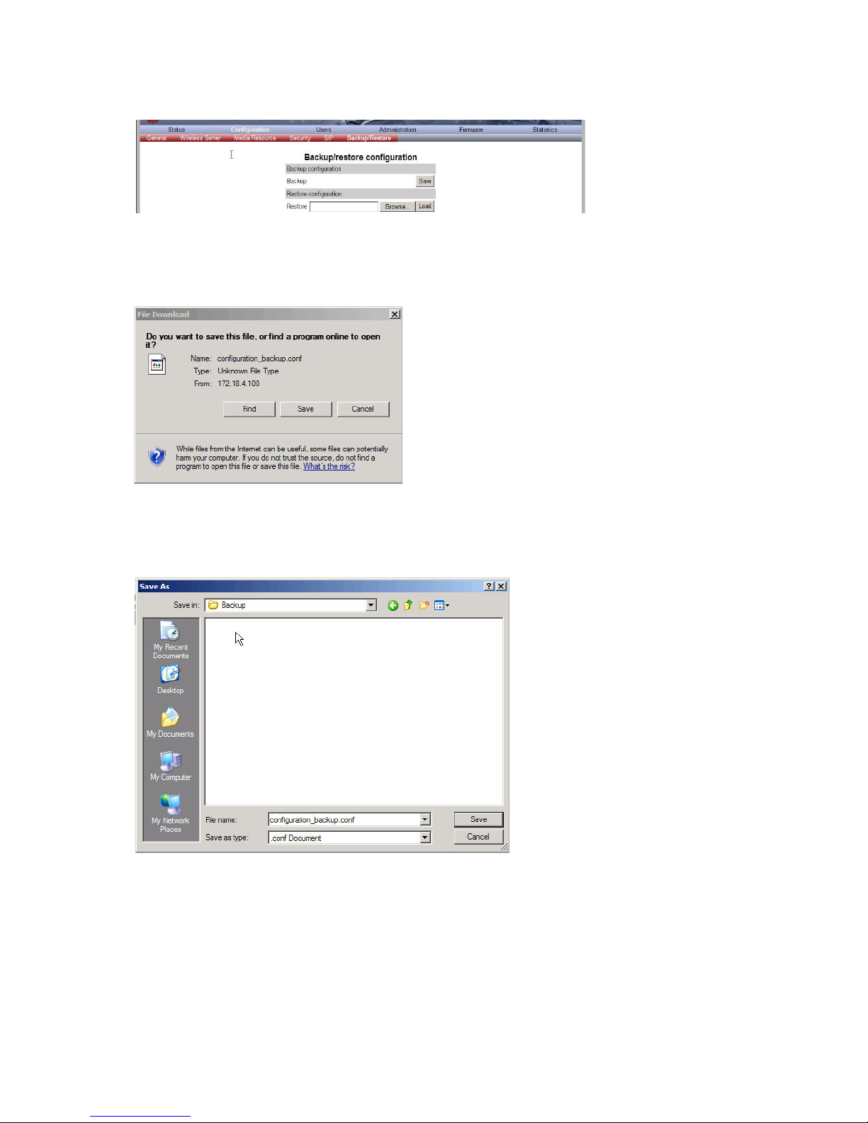
Spectralink IP-DECT Server 6500 Installation and Configuration Guide
14215700 Version 3.0
April, 2014 86
Figure 74 Adm. Page Wireless Server: Configuration/Backup/Restore page
2 Click Save.
A File Download dialog box appears.
Figure 75 File Download dialog box
3 Click Save.
A Save As dialog box appears.
Figure 76 Save As dialog box
4 Indicate in which folder and under what name the file should be saved, and then click Save.
Page 89

Spectralink IP-DECT Server 6500 Installation and Configuration Guide
14215700 Version 3.0
April, 2014 87
Restoring Configuration File
This section describes how to restore a configuration file.
1 Click Configuration, and then click Backup/Restore.
Figure 77 Adm. Page Wireless Server: Configuration/Backup/Restore page
2 Click Browse.
A Choose File dialog box appears.
Figure 78 Adm. Page: Choose File dialog box
3 Select the file in question, and then click Open.
4 Click Load.
5 Click OK.
The configuration file is restored in the system.
Updating the Spectralink IP-DECT Server 6500
The software of the Spectralink IP-DECT Server 6500 can be updated. To update the software
you load a file to the system. Contact your distributor for newest software.
Updating Spectralink IP-DECT Server 6500 Firmware
1 Click Firmware, and then click Wireless Server.
Page 90
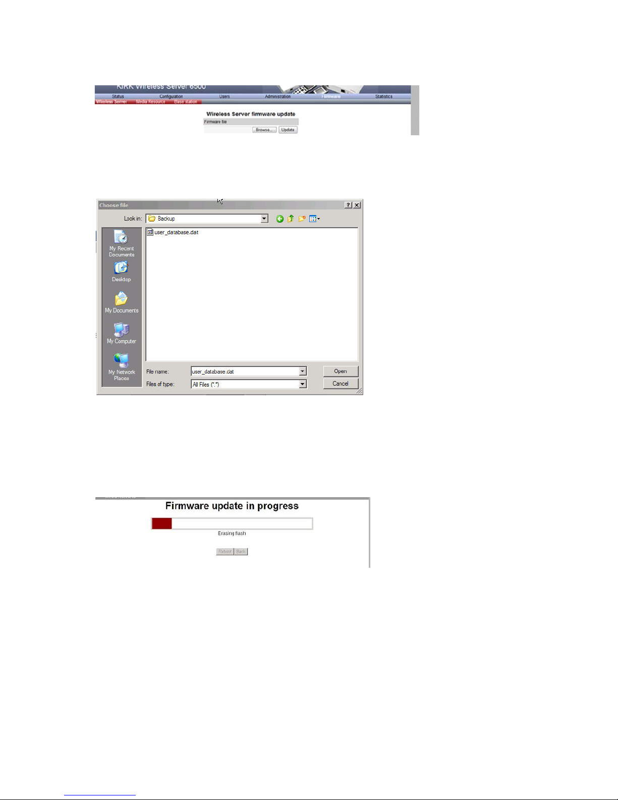
Spectralink IP-DECT Server 6500 Installation and Configuration Guide
14215700 Version 3.0
April, 2014 88
Figure 79 Adm. Page Wireless Server: Firmware/Wireless Server page
2 Click Browse.
A Choose File dialog box appears.
Figure 80 Adm. Page: Choose File dialog box
3 Select the file in question, and then click Open.
4 Click Update.
Wait until the system has finished updating.
Warning: Do not cut power.
Figure 81 Adm. Page: Firmware Update Progress Bar
5 Optionally, you can block new calls during a firmware update by clicking Administration, and
then Wireless Server.
Page 91

Spectralink IP-DECT Server 6500 Installation and Configuration Guide
14215700 Version 3.0
April, 2014 89
Figure 82 Adm. Page Wireless Server: Administration/Wireless Server page
Under Service Status click Block.
12.0.0.1 Click Update to update the Spectralink IP-DECT Server 6500 firmware. The
system prompts for a restart, when the firmware update is complete.
6 If you have blocked new calls during a firmware update, enable new calls again by clicking
Administration, then Wireless Server and then clicking Allow.
Restarting the Spectralink IP-DECT Server 6500
Some configuration changes requires a restart in order to take effect. A reset restarts the
Spectralink IP-DECT Server 6500 software.
You must restart the system after the following procedures:
• Configuration
• Uploading of configuration data
• Uploading of firmware
Operating System of Spectralink IP-DECT Server 6500
When restarting the operating system of the Spectralink IP-DECT Server 6500 all calls are
terminated and the Spectralink IP-DECT Server 6500 is reset.
1 Click Administration, and then click Wireless Server.
Note
Changes that require a restart are marked by 2 stars **.
Page 92

Spectralink IP-DECT Server 6500 Installation and Configuration Guide
14215700 Version 3.0
April, 2014 90
Figure 83 Adm. Page Wireless Server: Administration/Wireless Server page
2 After Wireless Server Uptime click Reboot now or Reboot idle (when active calls have
ended).
A warning box appears.
Figure 84 Warning box
3 Click OK.
Spectralink Media Resources
Changing System User Name and Password
From the Administration Page it is possible to change the user name and password for the system.
1 Click Configuration, and then click Security.
Figure 85 Adm. Page Media Resource: Configuration/Security page
2 In the Current password field, type the current password.
3 In the New user name field, type a user name.
4 In the New password field, type a new password
5 In the New password again field, type the new password again to confirm it.
6 Click Save to change the password.
Page 93

Spectralink IP-DECT Server 6500 Installation and Configuration Guide
14215700 Version 3.0
April, 2014 91
Reading System Information
Under Status it is possible to get general information about hardware version, firmware and
message logging. This information is useful in case of problem solving.
General Status Information
This page provides general system information such as hardware, firmware and OS Status
information.
1 Click Status, and then click General.
Figure 86 Adm. Page Media Resource: Status/General page
On the Status/General page the following information is available.
— General
— IP-address: current IP address of device
— NTP-Server: address of time server
— Time: current time on device
— Serial: Serial number of device
— MAC address: of device
— Product ID: from device
— Production Date: of device
— Hardware
— PartNoof hardware
— PCSHardware version of device_
— Firmware
— PartNosoftware part number
— PCSSoftware version
— BuildSoftware build number
—
— Quick status Red/Green/Grey
Page 94
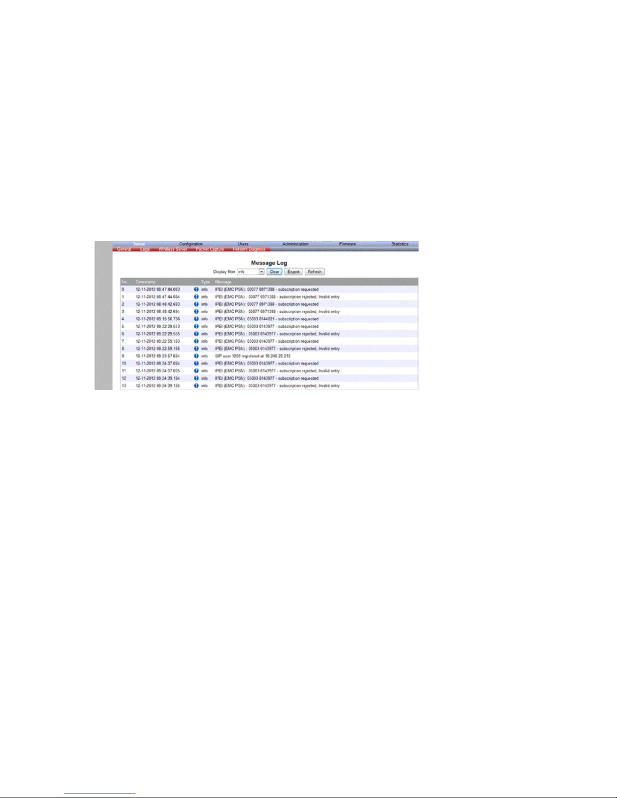
Spectralink IP-DECT Server 6500 Installation and Configuration Guide
14215700 Version 3.0
April, 2014 92
— SIPQuick status
— Base stationsQuick status
— Media resources Quick status
— ProvisioningQuick status
— NTPQuick status
Logs Information
This page provides logs information such as media resource connection, base station connection
and different types of status.
Figure 87 Adm. Page Media Resource: Status/Logs page
1 From the Display filter list you can select between emergency, critical, error, warning,
notice, info or debug depending on the logs you want to see.
The different types of status are:
— emergency (errors causing the system to malfunction for all calls)
— critical (events that do not occur under normal operation, cause minor malfunction)
— error (events that do not occur under normal operation, cause minor malfunction)
— warning (events that do not occur under normal operation, may cause malfunction)
— notice info (events that occur under normal operation, relevant to an administrator)
2 Click Status, and then click Logs.
3 Click Save if you want to save the logs in a file.
A Save As dialog box appears.
Page 95

Spectralink IP-DECT Server 6500 Installation and Configuration Guide
14215700 Version 3.0
April, 2014 93
Figure 88 Adm. Page: Save As dialog box
4 Indicate in which folder and under what name the file should be saved, and then click Save.
It is now possible to send the log files to authorized technicians for further support and problem
solving.
Reading Statistics
Statistic information about the media resource is retrieved from the Administration Page of the
Spectralink IP-DECT Server 6500.
Updating the Spectralink Media Resource Firmware
The software of the media resource can be updated. To update the software you load a file to the
system. Contact your distributor for newest software.
Updating Spectralink Media Resource Firmware
1 Click Firmware, and then click Media Resource.
Figure 89 Adm. Page Media Resource: Firmware/Media Resource page
Note
You can upload software directly from the Spectralink Wireless server under
Firmware/Wireless Server, Media Resource, Base Station..
Page 96

Spectralink IP-DECT Server 6500 Installation and Configuration Guide
14215700 Version 3.0
April, 2014 94
2 Click Browse.
A Choose File dialog box appears.
Figure 90 Adm. Page: Choose File dialog box
3 Select the file in question, and then click Open.
The file to select has the extension .bin.
4 Click Update.
Wait until the system has finished uploading.
Figure 91 Adm. Page: Firmware Update Progress Bar
5 Optionally, you can block new calls during a firmware update by clicking Administration
(Administration Page of Spectralink IP-DECT Server 6500), and then Wireless Server.
Figure 92 Adm. Page Wireless Server: Administration/Wireless Server page
Under Service Status click Block.
Page 97
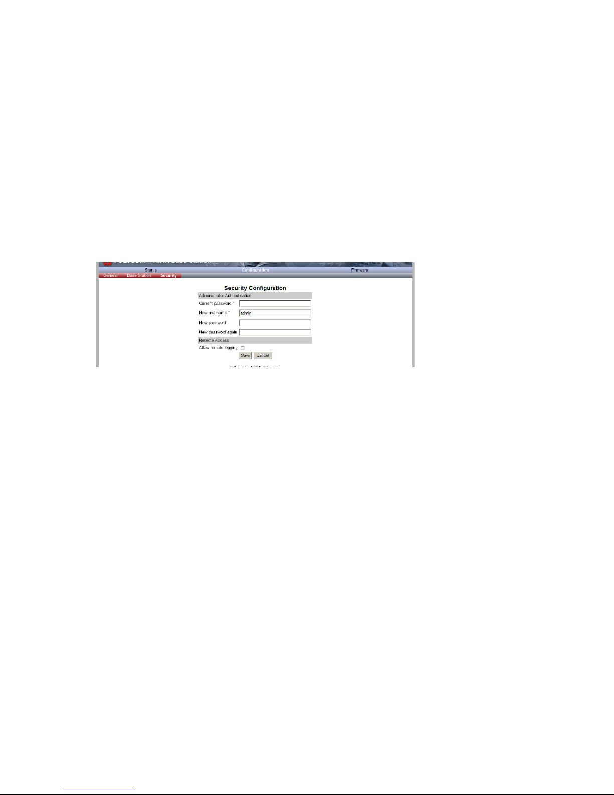
Spectralink IP-DECT Server 6500 Installation and Configuration Guide
14215700 Version 3.0
April, 2014 95
6 When the update is finished, click Reboot to execute the changes.
7 If you have blocked new calls during a firmware update, enable new calls again by clicking
Administration (Administration Page of Spectralink IP-DECT Server 6500), then Wireless
Server and then clicking Allow.
Spectralink IP-DECT Base Station
Changing System User Name and Password
From the Administration Page it is possible to change the user name and password for the system.
1 Click Configuration, and then click Security.
Figure 93 Adm. Page Base Station: Configuration/Security page
2 In the Current password field, type the current password.
3 In the New user name field, type a user name.
4 In the New password field, type a new password
5 In the New password again field, type the new password again to confirm it.
6 Click Save to change the password.
Reading System Information
Under Status it is possible to get general information about hardware version, firmware and
message logging. This information is useful in case of problem solving.
General Status Information
This page provides general system information such as hardware, firmware and OS Status
information.
1 Click Status, and then click General.
Page 98

Spectralink IP-DECT Server 6500 Installation and Configuration Guide
14215700 Version 3.0
April, 2014 96
Figure 94 Adm. Page Base Station: Status/General page
On the Status/General page the following information is available.
— General
— IP-address: current IP address of device
— NTP-Server: address of time server
— Time: current time on device
— Serial: Serial number of device
— MAC address: of device
— Product ID: from device
— Production Date: of device
— Hardware
— PartNoof hardware
— PCSHardware version of device_
— Firmware
— PartNosoftware part number
— PCSSoftware version
— BuildSoftware build number
—
— Quick status Red/Green/Grey
— SIPQuick status
— Base stationsQuick status
— Media resources Quick status
— ProvisioningQuick status
— NTPQuick status
Page 99
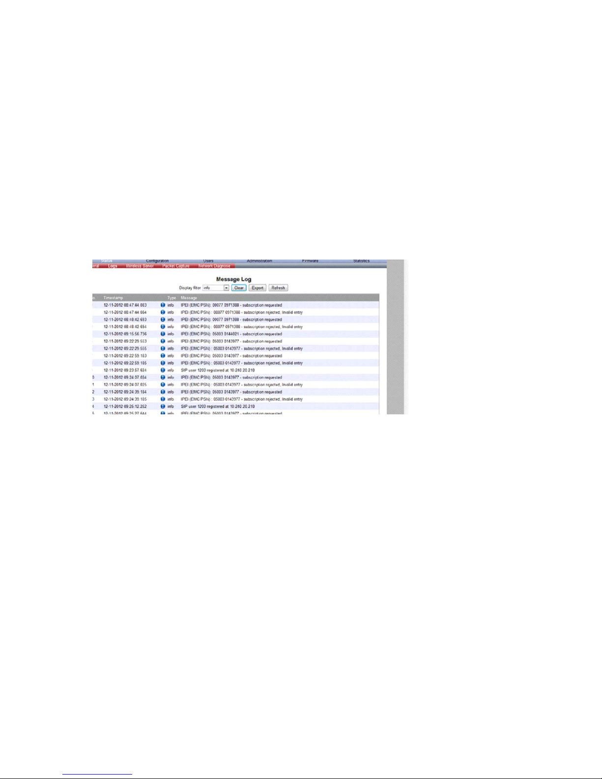
Spectralink IP-DECT Server 6500 Installation and Configuration Guide
14215700 Version 3.0
April, 2014 97
Logs Information
This page provides logs information such as media resource connection, base station connection
and different types of status.
The different types of status are:
— emergency (errors causing the system to malfunction for all calls)
— critical (events that do not occur under normal operation, cause minor malfunction)
— error (events that do not occur under normal operation, cause minor malfunction)
— warning (events that do not occur under normal operation, may cause malfunction)
— notice info (events that occur under normal operation, relevant to an administrator)
1 Click Status, and then click Logs.
Figure 95 Adm. Page Base Station: Status/Logs page
2 From the Display filter list you can select between emergency, critical, error, warning,
notice or info depending on the logs you want to see.
3 Click Save if you want to save the logs in a file.
A Save As dialog box appears.
Page 100
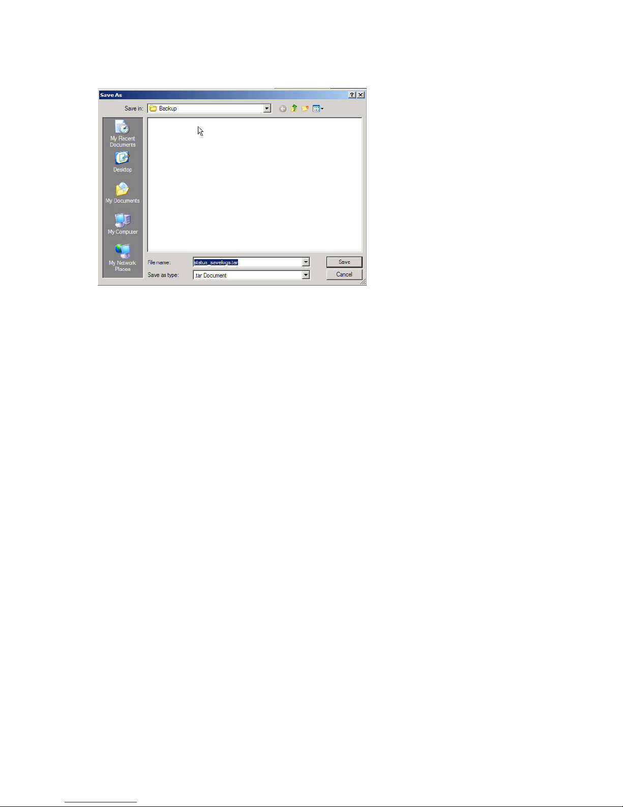
Spectralink IP-DECT Server 6500 Installation and Configuration Guide
14215700 Version 3.0
April, 2014 98
Figure 96 Adm. Page: Save As dialog box
4 Indicate in which folder and under what name the file should be saved, and then click Save.
It is now possible to send the log files to authorized technicians for further support and problem
solving.
Reading Statistics
Statistic information about the base station is retrieved from the Administration Page of the
Spectralink IP-DECT Server 6500.
Sync State of Base Station
You can get information about the synchronization state of the base station - the uptime and to
which radio unit it synchronizes on. This is useful when you want to get an overview of the base
stations and in case of problem solving.
Checking Sync State
1 Click Administration, and then click Base Station.
 Loading...