

Page 1

Link 6020 Wireless Telephone
Handset Administration Tool
Configuration and Administration
Link Wireless Telephone System
Part Number: 72-1204-00
Issue B
Page 2

SpectraLink Corporation Configuration and Administration
Link 6020 Wireless Telephone
Notice
SpectraLink Corporation has prepared this document for use by SpectraLink personnel and customers. The
drawings and specifications contained herein are the property of SpectraLink and shall be neither reproduced in
whole or in part without the prior written approval of SpectraLink, nor be implied to grant any license to make,
use, or sell equipment manufactured in accordance herewith.
SpectraLink reserves the right to make changes in specifications and other information contained in this
document without prior notice, and the reader should in all cases consult SpectraLink to determine whether
any such changes have been made.
The terms and conditions governing the sale of SpectraLink hardware products and the licensing of
SpectraLink software consist solely of those set forth in the written contracts between SpectraLink and its
customers. No representation or other affirmation of fact contained in this document including but not limited
to statements regarding capacity, response-time performance, suitability for use, or performance of products
described herein shall be deemed to be a warranty by SpectraLink for any purpose, or give rise to any liability of
SpectraLink whatsoever.
In no event shall SpectraLink be liable for any incidental, indirect, special, or consequential damages
whatsoever (including but not limited to lost profits) arising out of or related to this document, or the
information contained in it, even if SpectraLink has been advised, knew, or should have known of the
possibility of such damages.
Trademark Information
SpectraLink®
LinkPlus
Link
NetLink
SVP
Are trademarks and registered trademarks of SpectraLink Corporation.
The SpectraLink logo is a registered trademark in the United States of America and in other countries.
All other trademarks used herein are the property of their respective owners.
SpectraLink Corporation
5755 Central Avenue
Boulder, CO 80301
303 440 5330 or
800 676 5465
www.spectralink.com
Copyright © 2006, 2007 SpectraLink Corporation. All rights reserved
Information in this document is subject to change without notice and does not represent a commitment on the
part of SpectraLink Corporation. The software described in this document is furnished under a license and
may only be used pursuant to the terms of (1) SpectraLink's software license agreement available at
http://www.spectralink.com/softwareUpdates
between the user and SpectraLink Corporation OR (3) the terms and conditions previously agreed to in writing
between the user and an authorized SpectraLink reseller (each, the “Agreement”). The software may be used
only in accordance with the terms of the Agreement. No part of this manual, or the software described herein,
may be reproduced or transmitted in any form or by any means, electronic or mechanical, including
photocopying and recording, for any purpose except for the sole intent to operate the product or without the
express written permission of SpectraLink Corporation.
OR (2) the terms and conditions previously agreed to in writing
PN: 72-1204-00-B.doc Page 2
Page 3

SpectraLink Corporation Configuration and Administration
Link 6020 Wireless Telephone
WARNING: Changes or modifications to this equipment not approved by SpectraLink
Corporation may cause this equipment to not comply with part 15 of the FCC rules and
void the user’s authority to operate this equipment.
WARNING: SpectraLink products contain no user-serviceable parts inside. Refer servicing
to qualified service personnel.
IMPORTANT SAFETY INFORMATION
Follow these general precautions while installing telephone equipment:
• Never install telephone wiring during a lightning storm.
• Never install telephone jacks in wet locations unless the jack is specifically designed for
wet locations.
• Never touch uninsulated telephone wires or terminals unless the telephone line has
been disconnected at the network interface.
• Use caution when installing or modifying telephone lines
• When installing Base Stations outside or in buildings other than the one containing the
System Controller, take the following precaution:
If wiring for a Base Station exits a building—whether to reach an outdoor Base
Station location or to reach a Base Station in another building—the wiring must be
protected at both ends by a Quick Clip Fuse from Illinois Tool Works, Linx Division,
model number SCP-2X2. The Quick Clip Fuse replaces the bridging clips on the 66
blocks for all four connections to the non-internal Base Station.
PN: 72-1204-00-B.doc Page 3
Page 4

SpectraLink Corporation Configuration and Administration
Link 6020 Wireless Telephone
Table of Contents
1. About This Document 5
1.1 SpectraLink Corporation Model Numbers 5
1.2 Related Documents 5
1.3 Customer Support Hotline 5
1.4 Icons and Conventions 5
2. Configuration Overview 6
3. Standby Menus 7
3.1 Default Settings 8
4. Handset Administration Tool Installation 9
4.1 Installing the USB Driver 9
4.2 Install the Handset Administration Tool 13
5. Using the Handset Administration Tool 14
5.1 Connecting the Handset 14
5.2 Password Configuration 16
5.3 Error Information 17
5.4 Software Updates 17
5.5 Version 19
6. Site-Programmed Telephony Features 20
7. Software Maintenance 21
PN: 72-1204-00-B.doc Page 4
Page 5

SpectraLink Corporation Configuration and Administration
Link 6020 Wireless Telephone
1. About This Document
This document explains the configuration and administration of the Link 6020
Wireless Telephone (the handset) using the Handset Administration Tool, a software
utility developed by SpectraLink for this purpose. Link 6020 handsets are supported
on Link Wireless Telephone Systems (WTS) using the Link 150 M3 Master Control
Unit (MCU) or the Link 3000 MCU. MCU versions prior to the Mod-3 (M3) MCU
are not supported.
1.1 SpectraLink Corporation Model Numbers
This document covers the following registered model numbers:
Link 602X, PC232
1.2 Related Documents
Link 150 M3 MCU: Installation and Operation
Link 3000 MCU: Operator’s Console
Link 6020 Wireless Telephone and Accessories User Guide
Link 6020 Wireless Telephone Quick Reference Guide
Link 6020 Advanced Features Template
Available at http://www.spectralink.com/resources/manual_linkwts.jsp
LinkPlus Interface Guide
the type of PBX)
Available at http://www.spectralink.com/resources/manual_linkwts.jsp.
(72-0171-xx where xx indicates a number corresponding to
1.3 Customer Support Hotline
SpectraLink wants you to have a successful installation. If you have questions please
contact the Customer Support Hotline at 800 775 5330. The hotline is open
Monday through Friday, 6 a.m. to 6 p.m. Mountain time.
1.4 Icons and Conventions
This manual uses the following icons and conventions.
Caution! Follow these instructions carefully to avoid danger.
(72-0075-01)
(72-0059-02)
(72-1204-01)
(72-1201-00)
(72-1202-00)
NORM
PN: 72-1204-00-B.doc Page 5
Note these instructions carefully.
This typeface indicates a key, label, or button on the Handset
Administration Tool, MCU or Link Wireless Telephone.
Page 6

SpectraLink Corporation Configuration and Administration
Link 6020 Wireless Telephone
2. Configuration Overview
Configuration of the Link 6020 handset requires several preliminary steps. The MCU
must be programmed for system feature activation as detailed in
or
MCU: Installation and Operation
Link 3000 MCU: Operator’s Console
on which type of system is installed in the facility.
The handsets are shipped from the factory with correct software code. If updates are
available, they may be downloaded from the SpectraLink website
http://www.spectralink.com/softwareUpdates
. Contact Customer Service for
information about updates and available downloads.
Code updates are loaded into the handset through the Dual Charger. This device has
a USB port beside the power jack to connect it with a PC. The Handset
Administration Tool is a software utility that is installed on the PC and enables the
software downloads and handset configuration. This utility may be downloaded from
the SpectraLink website. It is also provided on the SpectraLink
CD.
These steps summarize the sequence for configuring handsets on a new Link WTS.
Link 150 M3
, depending
Installation Manuals
1. Configure the MCU for feature access per above references.
2. Download any available Link 6020 Wireless Telephone software updates to a PC
running Windows 2000 or Windows XP with a USB port.
3. Download the USB driver and the Handset Administration Tool.
4. Set up the Dual Charger for the Link 6020 Wireless Telephone and place the
handset in the Charger.
5. Install the USB driver software and the Handset Administration Tool software.
6. Use the Firmware tab of the Handset Administration Tool to download the
updated code to the handset.
7. Remove the handset from the Dual Charger and cycle the power for the settings
to take effect.
8. Record the feature settings for end users via the template provided for this
purpose.
The following sections describe these steps in detail.
PN: 72-1204-00-B.doc Page 6
Page 7
SpectraLink Corporation Configuration and Administration
Link 6020 Wireless Telephone
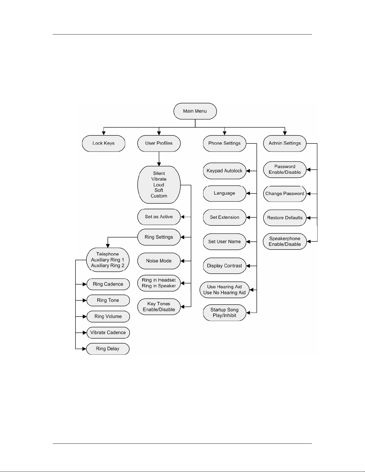
3. Standby Menus
The Link 6020 features a standby menu to configure user preferences and
administrative settings, including password protection for the administrative settings.
The standby menu is opened by pressing the
Cfg softkey from standby mode.
PN: 72-1204-00-B.doc Page 7
Page 8

SpectraLink Corporation Configuration and Administration
Link 6020 Wireless Telephone
3.1 Default Settings
One of the options on the handset’s Admin Settings menu is Restore Defaults. The
following is a list of the default settings.
User Profiles
Setting/profile Loud Soft Vibrate Silent Custom
Ring Cadence
Ring Tone Tone 1 Tone 1 Tone 1 Tone 1 Tone 1
Ring Volume
Vibrate Cadence
Ring Delay
Noise Mode Normal Normal Normal Normal Normal
Headset/Speaker Ring Speaker Speaker Speaker Speaker Speaker
Key Tones Enabled Enabled Disabled Disabled Enabled
PBX PBX Off Off PBX
7 3 1 1 5
Off Off PBX Off PBX
None None None None 5 Seconds
Handset Settings
Setting Default
Keypad Autolock Disabled
Language English
Set Extension [blank]
Set User Name [blank]
Display Contrast Medium
Use Hearing Aid
Startup Song
No
Play
Admin Settings
Setting Default
Disable Password 123456
Change Password 123456
Restore Defaults
Speakerphone Enabled
n/a
PN: 72-1204-00-B.doc Page 8
Page 9

SpectraLink Corporation Configuration and Administration
Link 6020 Wireless Telephone
4. Handset Administration Tool Installation
The Handset Administration Tool is a software utility for downloading software
updates to the handset and for configuration of the handset. This utility is installed
on a PC with a USB port that can be cabled to the USB port of the Dual Charger. It
is designed as a time-saving device for rapid administration and configuration of a
number of handsets. Configuration options include:
• Change the password or disable password protection
• Assist troubleshooting by recording error information
• Upgrade handset software
4.1 Installing the USB Driver
Necessary components:
• PC running Windows 2000 or Windows XP with a USB port
• Dual Charger for the Link 6020 Wireless Telephone
• Power supply for the appropriate country or region
• SpectraLink USB cable or comparable cable (with 5-pin “mini-B” connector)
1. Set up a folder for Link 6020 Wireless Telephone configuration on the PC and
download the programming software from the SpectraLink website
http://www.spectralink.com /softwareUpdates into this folder. Extract the
individual files from the zip file. The zip file from the website will contain the
USB.zip file.
If retrieving files from the SpectraLink
2. Set up a folder for the USB files and extract the two files from the zip file into
3. Place the Dual Charger on a flat, horizontal surface, and plug the power supply
4. Power off a Link 6020 Wireless Telephone and place it in the Charger. The
are available as two separate links on the Administration Software page.
this folder. These are named slnkusb.sys and slnkusb.inf.
The USB driver may be left on the
from there if preferred.
into the Dual Charger and into an appropriate wall outlet. Plug the USB cable
into the Dual Charger and into an available USB port on the PC.
handset will automatically power up in USB mode.
Installation Manuals
Installation Manuals
CD, the files
CD and installed
PN: 72-1204-00-B.doc Page 9
Page 10

SpectraLink Corporation Configuration and Administration
Link 6020 Wireless Telephone
5. Microsoft Windows will start the Found New Hardware Wizard and ask if it can
connect to Windows Update to search for software. Click the No, not this time
option. Click the Next button.
6. The next screen prompts you for information about installing the USB device.
Click the Install from a list or specific location option and click the Next button
PN: 72-1204-00-B.doc Page 10
Page 11

SpectraLink Corporation Configuration and Administration
Link 6020 Wireless Telephone
7. The next screen prompts you for the location. Click the Search for the best
driver in these locations
8. Clear the Search removable media check box. Select the Include this location in
the search
the Next button
check box and browse to the location of the USB driver files. Click
option.
The USB driver may be left on the
from there if preferred. In this case browse to the USB Driver folder on
the CD.
Installation Manuals
CD and installed
9. The Microsoft Wizard will display the following warning message. The USB
software has been fully tested in SpectraLink’s laboratories and will not harm
your system. Click the Continue Anyway button.
PN: 72-1204-00-B.doc Page 11
Page 12

SpectraLink Corporation Configuration and Administration
Link 6020 Wireless Telephone
10. The Microsoft Wizard will now install the software.
11. The final screen indicates that the USB driver has been successfully installed.
Click the Finish button to close the wizard and proceed with handset
configuration.
PN: 72-1204-00-B.doc Page 12
Page 13

SpectraLink Corporation Configuration and Administration
Link 6020 Wireless Telephone
4.2 Install the Handset Administration Tool
Note that there is no installer or uninstaller for the Handset
1. Navigate to the folder established in step 1 above and click the
2. Accept the SpectraLink Software License Agreement.
3. The HandsetAdmin Setup window allows you to run the program from its
Administration Tool since the program does not modify your system or
registry. It runs from its current location and stores its settings locally.
HandsetAdmin.exe file to run the utility.
current location or set up Start Menu shortcuts and/or move the program to a
different folder, if desired.
If you click the Run From Current Location button, the Handset Administration
Tool will start.
If you click the Setup…button, another window will help you set up shortcuts
and, if desired, move the .exe file to another location. Click the new shortcut to
open the program.
PN: 72-1204-00-B.doc Page 13
Page 14

SpectraLink Corporation Configuration and Administration
Link 6020 Wireless Telephone
5. Using the Handset Administration Tool
The Handset Administration Tool uses indicators to alert you to the status of the
action being performed.
• Green – the adjacent label is “true” and this state is desirable or required.
• Yellow – the adjacent label is “true” and this state requires caution or attention.
For example, a yellow New folder indicator cautions that the file path will be
created. A yellow File exists indicator cautions that the file will be overwritten.
• Red – the adjacent label is “true” and this state is undesirable or is accompanied
by an error (in which case a message on the prompt line or a dialog box will
describe the nature of the error).
• Gray – the adjacent label is not “true”. E.g. the handset is not connected.
• Blinking – file status indicators blink yellow when the file status is being queried
but is not yet known (for example: when attempting to access slow drives or
unresponsive network devices). File status indicators blink red when the path is
invalid (mistyped). The Handset indicator blinks when the handset’s password
needs to be entered.
A prompt line at the bottom of the window provides information about what action
should be taken or the status of the utility.
5.1 Connecting the Handset
1. The first window prompts you to insert a handset into the Dual Charger. The tab
labels describe each of the available functions.
2. Insert the handset into the Dual Charger.. When the handset is inserted for the
first time, the password must be entered.
3. Enter the password.
PN: 72-1204-00-B.doc Page 14
Page 15

SpectraLink Corporation Configuration and Administration
Link 6020 Wireless Telephone
The default password is 123456. If you select the Remember password check
box, the password is retained as the default password for all handsets. Unique
passwords for each handset are not remembered.
4. Click the Submit button
5. When a connection is established between the program and the handset, the
Handset connected indicator turns green and Connected displays on the prompt
line. The handset is now ready for configuration.
PN: 72-1204-00-B.doc Page 15
Page 16

SpectraLink Corporation Configuration and Administration
Link 6020 Wireless Telephone
5.2 Password Configuration
In order to change a password, the existing password must be entered. Then the new
password may be entered and confirmed. If the
cleared, no password will be required to access Admin Settings in the handset’s
standby menu.
A password may be up to 18 characters.
Enable password check box is
The following table illustrates how numbers and letters are entered on the handset’s
keypad. The CAPS/caps softkey toggles to allow both upper and lowercase letters.
caps CAPS
Key
1
1
1
2 a b c 2 A B C
2
3 d e f 3 D E F
3
4 g h I 4 G H I
4
5 j k l 5 J K L
5
6 m n o 6 M N O
6
7 p q r s 7 P Q R S
7
8 t u v 8 T U V
8
9 w x y 9 W X Y
9
0 0
0
* . ! $ % & ‘ ( ) + , : ; / \ = @ ~
*
<space>
#
PN: 72-1204-00-B.doc Page 16
Page 17

SpectraLink Corporation Configuration and Administration
Link 6020 Wireless Telephone
5.3 Error Information
The Error info tab provides a utility to assist the SpectraLink Customer Service team
to troubleshoot handset errors. When directed by Customer Service, this utility
enables you to save any errors as a file which can then be sent to SpectraLink for
handling.
Use the Browse button to establish the path and then enter the filename. Future
saves will point to this same location as the default so that the same file may be
overwritten if desired. The File time window displays the modification timestamp of
the file in the Save…as window.
Save the file by clicking the Get file button. The file will be copied from the handset
to the location. The Read/Write indicators will reflect the action as it occurs. File
transfer progress is shown by a progress indicator above the prompt line.
This sample screen shows a new file being created in an existing folder.
5.4 Software Updates
The Firmware tab allows you to update the software in the handset by copying it
from a location on your computer to the handset memory.
Download the software update from the SpectraLink website at
http://www.spectralink.com/ softwareUpdates
Extract the
Use the Browse button to locate the software file. The File time window displays the
modification timestamp of the file in the Firmware file window. The file version and
handset version will also display for comparison. Verify that the information
indicates that the correct file will be downloaded and then click the Update button.
PN: 72-1204-00-B.doc Page 17
pt28c.bin file from the zip to a folder set up for this purpose.
.
Page 18

SpectraLink Corporation Configuration and Administration
Link 6020 Wireless Telephone
The file will be copied from the location to the handset. The Read/Write indicators
will reflect the action as it occurs.
Should an Error indication occur, retry the update after ensuring that the handset is
properly seated and that the USB cable is in good condition and connected securely.
Contact Customer Service if an error persists.
If you are trying to update the software and the file being downloaded is
incompatible, an error message will display and the download will stop. Contact
Customer Service for help should this situation occur.
Note that the firmware file path, file time, file version and handset version shown in
the above example screen are for illustration only.
While a firmware update is in progress, you may open other tabs and the Handset
indicators shown on those screens will inform you of the status of the update.
PN: 72-1204-00-B.doc Page 18
Page 19

SpectraLink Corporation Configuration and Administration
Link 6020 Wireless Telephone
5.5 Version
The Version tab displays the Handset Administration Tool version and the handset’s
serial number and firmware version.
Note that versions may differ from those shown on the above display.
PN: 72-1204-00-B.doc Page 19
Page 20

SpectraLink Corporation Configuration and Administration
Link 6020 Wireless Telephone
6. Site-Programmed Telephony Features
Advanced telephony features are programmed onsite according to the features
provided by the PBX. The MCU is programmed for system feature activation as
detailed in
Operator’s Console
Link 150 M3 MCU: Installation and Operation
, depending on which type of system is installed in the facility.
During this process, the handset keypad is mapped to the features as described in the
LinkPlus Interface Guide
that corresponds with the PBX system installed in the
facility.
The following table is provided so that the mapping can be recorded here. This same
table is also included in the
(72-1201-00) and the
Link 6020 Wireless Telephone and Accessories User Guide
Link 6020 Wireless Telephone Quick Reference Guide
(72-1202-00). The table in the guide may be customized with facility-specific
settings either by hand or with the
1204-01) available on the
SpectraLink Documentation
Link 6020 Advanced Features Template
The template allows you to customize this table in Microsoft Word and print it on
stock labels to be affixed to the guide. Open the template, fill in the table and
copy/paste it into the remaining cells. Print on stock labels (Avery address label
#5168).
or
Link 3000 MCU:
CD or website.
(72-
Feature Key Press
Transfer FCN + _________
Forward
Conference
Camp on
Redial
Voicemail
Flash
Application mode
_________
_________
_________
_________
_________
_________
FCN + _________
FCN + _________
FCN + _________
FCN + _________
FCN + _________
FCN + _________
FCN + _________
FCN + _________
FCN + _________
FCN + _________
FCN + _________
FCN + _________
FCN + _________
PN: 72-1204-00-B.doc Page 20
Page 21

SpectraLink Corporation Configuration and Administration
Link 6020 Wireless Telephone
7. Software Maintenance
The Link 6020 Wireless Telephones use proprietary software programs written and
maintained by SpectraLink Corporation. The software versions that are running on
the handsets can be displayed during power on by holding down the
using the Handset Administration Tool, the version displays under the Firmware tab
in the handset ver window.
Obtaining software updates
SpectraLink Customer Service or an authorized dealer will provide information
about software updates and how to obtain the software (for example, downloading
updates from a website.)
Upgrading handsets via the Handset Administration Tool
See Section 5.4
Software Updates.
Upgrading handsets via over-the-air downloading (Link 3000 WTS only)
After software updates are obtained from SpectraLink, they must be transferred to
the Link 3000 MCU by SpectraLink Customer Service or an authorized dealer.
END button. If
With over-the-air downloading (OTAD), the download function in the Link 6020
handset checks its software version periodically during normal operation. If there is
any discrepancy the handset immediately begins to download the update from the
MCU. This normally takes less than a minute. During the download, the downloader
icon displays on the status bar. While memory is being erased and reprogrammed
Do Not Power Off displays in the text area of the handset.
When the update is complete, the handset reboots. The handset displays the
extension number once it is ready for use.
Download failure or recovery messages
If the software downloaded from the MCU is incompatible with the handset
hardware, the handset displays the incompatible software icon on the status bar.
The handset does not load incompatible software into memory. It remains
operational running the pre-existing software and the incompatible software icon
remains on until the handset is power cycled and the handset software on the MCU
is corrected.
PN: 72-1204-00-B.doc Page 21
 Loading...