

Page 1
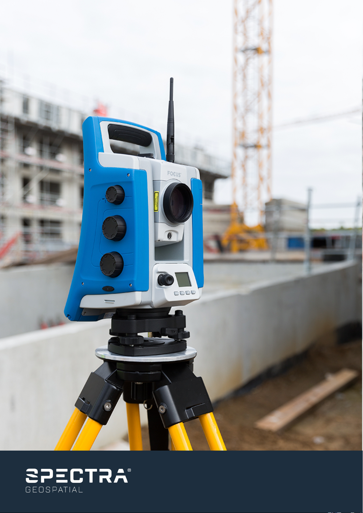
FOCUS 35 Total Station
User Guide
Page 2

Corporate Office
Spectra Geospatial
10368 Westmoor Drive
Westminster, CO 80021, USA
+1-720-587-4700 Phone
888-477-7516 (Toll free in USA)
www.spectrageospatial.com
Copyright and trademarks
© 2015–2019, Trimble Inc. All rights reserved.
Spectra Geospatial is a division of Trimble Inc. Spectra,
the Spectra Geospatial logo, and FOCUS are trademarks of
Trimble Inc., registered in the United States and in other
countries. GeoLock, LockNGo, Ranger, T41, StepDrive, and
SurveyPro are trademarks of Trimble Inc.
Microsoft, Windows, Windows Mobile, and Windows Vista,
are either registered trademarks or trademarks of
Microsoft Corporation in the United States and/or other
countries. The Bluetooth word mark and logos are owned
by the Bluetooth SIG, Inc. and any use of such marks by
Trimble Inc. is under license. All other trademarks are the
property of their respective owners.
Release Notice
This is the August 2019 release (Revision A) of the FOCUS
35 Total Station User Guide. It applies to version 2.00 of
the software.
Product Limited Warranty Information
For applicable product Limited Warranty information,
please refer to the Limited Warranty Card included with
this product, or consult your local Spectra Geospatial
authorized dealer.
Updates and new products
To obtain information regarding updates and new
products, contact your Spectra Geospatial distributor or
visit the Spectra Geospatial website at
www.spectrageospatial.com.
Notices
Australia and New Zealand
This product complies with the regulatory
requirements of the Australian Communications
and Media Authority (ACMA) EMC framework, thus satisfying
the requirements for RCM-Marking and sale within Australia
and New Zealand.
Canada
This device complies with Industry Canada license-exempt
RSS standard(s). Operation is subject to the following two
conditions:
(1) this device may not cause interference, and
(2) this device must accept any interference, including
interference that may cause undesired operation of the
device.
Le présent appareil est conforme aux CNR d'Industrie
Canada applicables aux appareils radio exempts de
licence. L'exploitation est autorisée aux deux conditions
suivantes:
(1) l'appareil ne doit pas produire de brouillage, et
(2) l'utilisateur de l'appareil doit accepter tout brouillage
radioélectrique subi, même si le brouillage est susceptible
d'en compromettre le fonctionnement.
This device has been designed to operate with an antenna
having a maximum gain of 2.0 dBi. Antenna having a
higher gain is strictly prohibited per regulations of
Industry Canada. The required antenna impedance is 50
ohms. To reduce potential radio interference to other
users, the antenna type and its gain should be so chosen
that the equivalent isotropically radiated power (EIRP) is
not more than that required for successful
communication. Operation is subject to the following two
conditions: (1) this device may not cause interference, and
(2) this device must accept any interference, including
interference that may cause undesired operation of the
device.
Devices marked with Part Numbers 78731035 (78431035),
78732035 (78432035), 78733035 (78433035), 78735035
(78435035),78742035 (78542035), 78743035 (78543035),
and 78745035 (78545035) contain radio module with IC:
4492A-2410G.
The devices marked with Part Numbers 78733035
(78433035), 78735035 (78435035), 78751035 (78441035),
78752035 (78442035), 78753035 (78443035) and 78755035
(78445035) contains a Bluetooth radio module with IC:
6100 NM230NF.
FOCUS 35 TotalStation User Guide | 2
Page 3
Europe
This product has been tested and found to comply with
relevant requirements pursuant to European Council
directives, thereby satisfying the requirements for CE
marking and sale within the European Economic Area
(EEA).
Applicable directives:
RED Directive 2014/53/EU
RoHS Directive 2011/65/EU
The compliance to the applicable requirements is detailed
in the official Declaration of Conformity document, which
is filed at Spectra Geospatial.
For product recycling instructions and more information,
please go to www.spectrageospatial.com/weee-and-rohs/
Recycling in Europe: To recycle Spectra
Geospatial WEEE (Waste Electrical and
Electronic Equipment, products that run on
electrical power.), Call +31 497 53 24 30, and ask
for the "WEEE Associate". Or, mail a request for
recycling instructions to:
Spectra Geospatial Europe BV
c/o Menlo Worldwide Logistics
Meerheide 45
5521 DZ Eersel, NL
78735035 (78435035),78742035 (78542035), 78743035
(78543035), and 78745035 (78545035) contain radio
module with FCC ID: HSW- 2410G.
The devices marked with Part Numbers 78731035
(78431035), 78732035 (78432035), 78733035 (78433035),
78735035 (78435035), 78751035 (78441035), 78752035
(78442035), 78753035 (78443035), and 78755035
(78445035) contains a Bluetooth radio module with FCC ID:
TLZ-NM230NF.
This device complies with Part 15 of the FCC rules.
Operation is subject to the following two conditions:
(1) This device may not cause harmful interference, and
(2) This device must accept any interference received,
including interference that may cause undesired
operation.
Taiwan
Battery Recycling Requirements. The product
contains a removable Lithium-ion battery.
Taiwanese regulations require that waste batteries are
recycled.
USA
Note: This equipment has been tested and found to
comply with the limits for a Class A digital device, pursuant
to part 15 of the FCC Rules. These limits are designed to
provide reasonable protection against harmful
interference when the equipment is operated in a
commercial environment. This equipment generates, uses,
and can radiate radio frequency energy and, if not
installed and used in accordance with the instruction
manual, may cause harmful interference to radio
communications.
Operation of this equipment in a residential area is likely
to cause harmful interference in which case the user will
be required to correct the interference at his own
expense.
Changes and modifications not expressly approved by the
manufacturer or registrant of this equipment can void
your authority to operate this equipment under Federal
Communications Commission rules
The antenna used for this transmitter must be installed to
provide a separation distance of at least 20 cm from all
persons and must not be co-located or operating in
conjunction with any other antenna or transmitter:
Devices marked with Part Numbers 78731035
(78431035),78732035 (78432035), 78733035 (78433035),
FOCUS 35 TotalStation User Guide | 3
Page 4

Important Information
Before using the Spectra® Geospatial FOCUS® 35 total station, make sure that you understand this user
guide, as well as all equipment and job site safety requirements.
Safety Information
l Instruments and original accessories from Spectra Geospatial must only be used for the intended
purpose.
l Operate the instrument only in compliance with the operating conditions specified. Do not point the
telescope directly at the sun.
l Do not use the instrument and accessories in rooms with danger of explosion.
l Protect operator and instrument sufficiently at the site of measurement (e.g., construction site,
roads, etc.). Observe any relevant national regulations and the Road Traffic Act.
l Do not carry out surveying work in a thunderstorm to avoid being struck by lightning.
l Do not modify the instrument.
l Do not use the instrument if there are any visible damages.
l Only authorized Spectra Geospatial service centers have permission to repair this product.
Laser Safety
This equipment has been tested and found to comply with IEC 60825-1:2014 and IEC 60825-1:2007 and 21
CFR 1040.10 and 1040.11 except for deviations pursuant to Laser Notice No. 50, dated July 26, 2007.
WARNING – Use of controls or adjustments or performance of procedures other than those
specified herein may result in hazardous LED or laser radiation exposure. As with any bright light
source, such as the sun, electric welding arcs or arc lamps, common sense applies. DO NOT look
into the laser aperture when the laser is on. For further information regarding laser safe use of
laser, refer to IEC standard 60825-1:2014.
NOTE – For security reasons the Spectra Geospatial FOCUS 35 User Guide describes the warnings
and regulations of the IEC 60825-1:2014 and the warnings and recommendations of the German
industrial regulation BGV B2 (updated print version April 2007).
In accordance with this German regulation, a responsible person must be identified for laser safety. All
absolute vital power to fulfill this task has to be transferred to this person.
Please ensure that you are aware of any national laws and regulations applicable in the country of
operation, concerning laser safety precautions and any other occupational safety and health issues that
FOCUS 35 TotalStation User Guide | 4
Page 5

may be encountered. All national laws and regulations take precedence over foreign or international
standards.
Laser Safety Questions
Address any questions you may have about laser safety to:
Spectra Geospatial
5475 Kellenburger Road
Dayton, OH USA 45424-1099
Attention: Laser Safety Officer, Quality Assurance Group
Phone (937) 233-8921 ext 824 or (800) 538-7800
Fax (937) 233-9661
CLASS 3R Laser Product
The FOCUS 35 Total Station is a CLASS 3R LASER PRODUCT and contains different light sources.
Distance Measurement and Laser Pointer
The Distance Measuring Unit in reflectorless mode and in Laser Pointer mode produces visible Laser light
emerging at the centre of the telescope objective. Product conforms to Class 3R in accordance with IEC
60825-1:2014 and IEC 60825-1:2007 “Safety of laser devices”. The product complies with FDA
21CFR1040.10 and 1040.11.
Beam divergence 0.4 mrad
Modulation frequency 400 MHz*
Max. Output power <5 mW
Wavelength 660 nm
Measuring uncertainty ±5%
*Not valid for Laser Pointer
FOCUS 35 TotalStation User Guide | 5
Page 6
WARNING – The use of Laser Class 3R equipment can be dangerous for the eyes. The risk for eye
damage is minimized through the radiation limit of 5 mW (FOCUS 35 at 660 nm).
Do not stare directly into the beam.
Do not direct the beam towards reflective surfaces (prisms, mirrors, metallic surfaces, or
windows) or towards other people.
Precautions should be taken to ensure that persons do not look with an optical instrument directly
into the beam.
Dazzle flash-blindness and afterimages may be caused by a beam from a Class 3R laser product,
particularly under low ambient light conditions. This may result in temporary disturbance of vision.
Do not operate any equipment or vehicles if such disturbance of vision occurs.
In a distance of 80 m (262 ft) from an instrument the radiation conforms to Laser Class 1. In Laser
Class 1 a direct intrabeam viewing is not hazardous.
Take the following precautions while using a Class 3R instrument in order to minimize the risks of
personal injury:
l Only use the instrument’s Laser Class 3R function when absolutely necessary.
l Set up the laser beam above or below human eye level wherever practicable.
l Make sure that the area where the Class 3R instruments are used is marked with appropriate
laser warning signs.
l Do not measure towards prisms up to 1,000 m (3,280 ft) in reflectorless mode.
l Make sure that unauthorized personnel do not get access to the instrument.
The Distance Measuring Unit in prism mode produces visible laser light emerging at the center of the
telescope objective. Product conforms to Class 1 in accordance with IEC 60825-1:2014 and IEC 608251:2007 “Safety of laser devices”.
Max. output power < 20 µW
WARNING – Class 1 laser products are safe in normal use under reasonable conditions of operation
and are not harmful to the eyes provided that the products are used and maintained in accordance
with the instructions.
FOCUS 35 TotalStation User Guide | 6
Page 7

Tracklight
Tracklight produces visible LED light emerging from an objective above/below the telescope objective.
LEDs are not in scope of IEC 60825-1:2014 “Safety of laser devices”. Product is in accordance with IEC
62471: 2006.
Beam divergence 70mrad
Max. output power 0.4mW (red) and 0.2mW (green)
Wavelength 645nm (red) and 520nm (green)
Measuring uncertainty ± 5%
LockNGo Tracker
The LockNGo™ Tracker produces an invisible laser beam emerging at the center of the telescope
objective. Conforms to Class 1 in accordance with IEC 60825-1:2014 and IEC 60825-1:2007 “Safety of laser
devices”. The product complies with FDA 21CFR1040.10 and 1040.11.
Beam divergence (Hz x V) 40mrad x 30mrad
Pulse duration 144µs
Max. pulse frequency 109Hz
Max. Peak Power 2.22mW
Max. Mean Power 0.035mW
Wavelength 850nm
Measuring uncertainty ± 5%
For instrument labeling, see Laser Information, page 41.
FOCUS 35 TotalStation User Guide | 7
Page 8

Battery Safety
WARNING – Do not damage the rechargeable Lithium-ion battery. A damaged battery can cause
an explosion or fire, and can result in personal injury and/or property damage. To prevent injury or
damage:
l Do not use or charge the battery if it appears to be damaged. Signs of damage include, but are
not limited to, discoloration, warping, and leaking battery fluid.
l Do not expose the battery to fire, high temperature, or direct sunlight.
l Do not immerse the battery in water.
l Do not use or store the battery inside a vehicle during hot weather.
l Do not drop or puncture the battery.
l Do not open the battery or short-circuit its contacts.
WARNING – Avoid contact with the rechargeable lithium-ion battery if it appears to be leaking.
Battery fluid is corrosive, and contact with it can result in personal injury and/or property damage.
To prevent injury or damage:
l If the battery leaks, avoid contact with the battery fluid.
l If the battery fluid gets into your eyes, immediately rinse your eyes with clean water and seek
medical attention. Do not rub your eyes!
l If battery fluid gets onto your skin or clothing, immediately use clean water to wash off the
battery fluid.
WARNING – Charge and use the rechargeable Lithium-ion battery only in strict accordance with
the instructions. Charging or using the battery in unauthorized equipment can cause an explosion
or fire, and can result in personal injury and/or equipment damage. To prevent injury or damage:
l Do not charge or use the battery if it appears to be damaged or leaking.
l Charge the lithium-ion battery only in a Spectra Geospatial product that is specified to charge
it. Be sure to follow all instructions that are provided with the battery charger.
l Discontinue charging a battery that gives off extreme heat or a burning odor.
l Use the battery only in Spectra Geospatial equipment that is specified to use it.
l Use the battery only for its intended use and according to the instructions in the product
documentation.
FOCUS 35 TotalStation User Guide | 8
Page 9

Environmental Information
NOTICE FOR EUROPEAN UNION CUSTOMERS
Spectra Geospatial is pleased to announce a new recycling program for our European Union
customers. We recognize the importance of minimizing the environmental impacts of our
products and we endeavor to meet your needs, not only when you purchase and use our
products, but also when you are ready to dispose of them. That is why Spectra Geospatial is
actively pursuing, and will continue to pursue, the expanded use of environment friendly
materials in all its products, and why we have established a convenient and environmentally
friendly recycling program.
As Spectra Geospatial makes additional recycling facilities available for your use, we will post their
locations and contact information to our Recycling Instructions web page.
For product recycling instructions and more information, please go to
www.spectrageospatial.com/weee-and-rohs.
To recycle Spectra Geospatial WEEE in Europe, do one of the following:
Call +31 497 53 2430, and ask for the “WEEE Associate”
Mail a request for recycling instructions to:
Spectra Geospatial
c/o Menlo Worldwide Logistics
Meerheide 45
5521 DZ Eersel, NL
FOCUS 35 TotalStation User Guide | 9
Page 10

Contents
Important Information 4
Safety Information 4
Laser Safety 4
Laser Safety Questions 5
CLASS 3R Laser Product 5
Distance Measurement and Laser Pointer 5
Tracklight 7
LockNGo Tracker 7
Battery Safety 8
Environmental Information 9
1 Introduction 14
Related Information 14
Technical Assistance 14
Product Registration 14
2 Inspection, Care, and Maintenance 15
Inspecting the Container 15
Instrument Case 16
Instrument Case Contents 16
Instrument Versions 18
Care and Maintenance 18
Cleaning 19
Care of the Screens 19
Applying a Screen Protector for the Face 1 Screen (if fitted) 20
Removing Moisture 20
Transporting the Instrument 20
Servicing 20
3 Getting Started 21
Power Supply 22
Battery Safety and Environment Information 22
Checking the Instrument Battery Power Supply 23
Charging the Instrument Batteries 23
Inserting the Main Battery 24
Inserting the Face 1 Battery (if Available) 25
Suspend Mode 26
Instrument Description 27
Optical Plummet 29
Trigger Key 30
FOCUS 35 TotalStation User Guide | 10
Page 11

Contents
Control Unit Face1 (if fitted) 30
Control Functions Control Unit Face1 31
Operating System 31
Data Storage 31
Entering Information 32
Input Panel menu 32
Touch Screen 33
Control Unit Face2 34
Telescope Lens rain cover / sun shade 35
Connecting the Instrument to an Office Computer 36
Transferring Data Files 36
Setting Up and Running ActiveSync technology 37
Troubleshooting Windows Mobile Device Center Connection Issues 40
Install and enable .NET Framework 3.5 40
Registry Changes 40
Disconnecting ActiveSync 41
Laser Information 41
FOCUS 35 Total Station 42
4 Setup 45
Setup 46
Setup Stability 46
Measurement Stability 47
Starting the Instrument 47
Starting and Settings via Face1 Control Unit (if fitted) 48
First Steps in the Survey Pro software 49
Lookup and register the Survey Pro Software 50
Survey Pro Version Number 52
Starting and Settings via Face2 Control Unit 54
Security 57
PIN code 57
Activating or changing the PIN code 57
Using the PIN code to unlock the instrument 57
PUK code 58
Face2 Display while using the Survey Pro Software in different Instrument Versions 58
Brightness and Contrast 59
Main Menu Face2 - Information and Settings 60
Instrument Adjustment and Calibration 68
Compensator 69
Optical (HA/VA) Collimation and Trunnion Axis Tilt 69
LockNGo Tracker 69
Adjustment Routines in Survey Pro software (if available) 70
The Laser Pointer 72
Optical Plummet 77
Tribrach Circular Level 79
FOCUS 35 TotalStation User Guide | 11
Page 12

Contents
Measuring the Instrument Height 80
Pre Measurement Check List 82
Connecting to an External Data Collector 82
Connecting with Cable - LockNGo Instrument Version 82
Connecting with Bluetooth wireless technology - LockNGo Instrument Version 83
Connecting with Radio - Robotic and RX Instrument Versions 83
5 Instrument Operational Methods 84
Conventional Measurements with StepDrive Motor System 85
LockNGo Measurement 85
GeoLock Technology 85
Robotic Measurement 85
6 Instrument Technology 86
Angle Measuring Technology 87
Correction for Mislevelment 87
Correction for Collimation Errors 87
Correction for Trunnion Axis 89
Averaging Measurements to Reduce Sighting Errors 89
Distance Measuring Technology 90
Beam Divergence 91
Tracklight 93
StepDrive Motor System and Focus System 94
StepDrive 95
LockNGo Tracking Technology 97
Power Management 97
Instrument 98
Robotic Configuration 99
Power Supply 99
Internal Power Supply 99
Second Internal Power Supply 99
External Power Supply 99
External Communication 100
Radio 100
Bluetooth wireless technology 100
7 Accessories and Options 101
Rod and Prisms 102
Spectra Geospatial Standard Rod 102
Spectra Geospatial 360 Degree Prism 103
Robotic Components 103
External Radio 104
Cables for External Power Supply and Data Transfer 105
Cable for External Power Supply 105
Cable for Data Transfer 105
FOCUS 35 TotalStation User Guide | 12
Page 13

Contents
Control Unit Screen Protector 107
Transport Case Accessories 108
Carrying Straps 108
FOCUS 35 TotalStation User Guide | 13
Page 14

1
Introduction
Related Information
Technical Assistance
Product Registration
Welcome to the Spectra Geospatial FOCUS 35 Total Station User Guide. This manual describes how to set
up and use the Spectra® Geospatial FOCUS® 35 total station. Even if you have used an optical Total
Station before, Spectra Geospatial recommends that you spend some time reading this manual to learn
about the special features of this product.
Related Information
For more information about this product, please visit our web site at www.spectrageospatial.com.
Technical Assistance
If you have a problem and cannot find the information you need in the product documentation, contact
your local distributor.
Product Registration
To obtain information regarding updates and new products, contact your local Spectra Geospatial
distributor, or go to the Spectra Geospatial website, www.spectrageospatial.com.
FOCUS 35 TotalStation User Guide | 14
Page 15

Inspection, Care, and Maintenance
Inspecting the Container
Instrument Case
Care and Maintenance
Transporting the Instrument
Servicing
2
Inspecting the Container
Inspect the shipping container. If the container arrives in poor condition, examine the equipment for
visible damage. If damage is found, immediately notify the carrier and your Spectra Geospatial sales
representative. Keep the container and the packing material for the carrier to inspect.
FOCUS 35 TotalStation User Guide | 15
Page 16
2 Inspection,Care, and Maintenance
Instrument Case
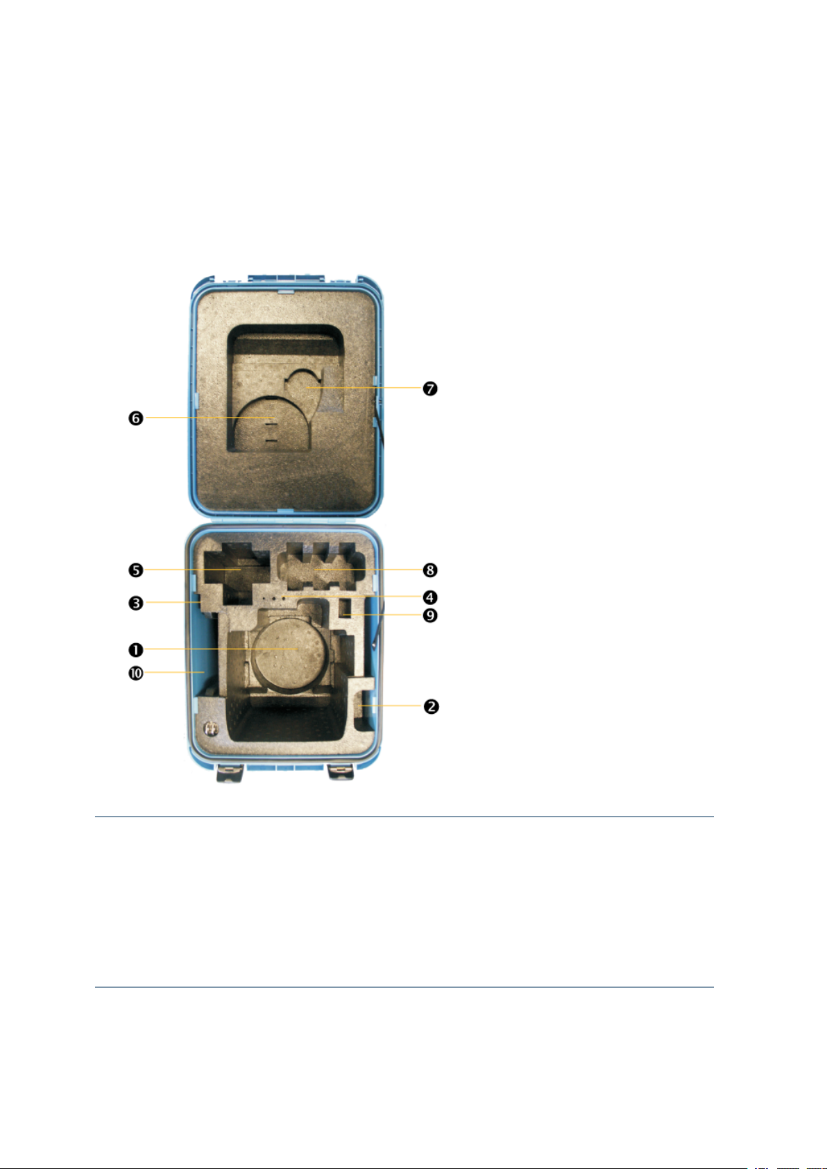
When unpacking the instrument, check that all ordered items are received. Below is an example of
where all items can be placed in the instrument case.
Instrument Case Contents
FOCUS 35 instrument
c
Instrument rain cover
d
Warranty Card, WEEE information, Certificate
e
Allen key for optical plummet (1.3 mm), Allen key for EDM/Coarse sight (1.5 mm) and adjustment
f
key for tribrach bubble
Data Collector
g
1
FOCUS 35 TotalStation User Guide | 16
Page 17

2 Inspection,Care, and Maintenance
Cable between instrument and computer1; Cable between instrument and USB flash drive
h
(optional)
Telescope lens rain cover / sun shade
i
Instrument batteries (space for 3 batteries) (optional)
j
USB flash drive (optional)
k
Getting started guide (optional); Laser adjustment target; Screen protectors
l
CAUTION – If the instrument is equipped with an optional DIN adapter for DIN tribrach, the DIN
tribrach must be removed before the instrument is placed in the instrument case.
1
Not all data collectors are designed to fit this space.
FOCUS 35 TotalStation User Guide | 17
Page 18
2 Inspection,Care, and Maintenance
Contains
FCCID: HSW-2410G
IC:4492A-2410G
30-2”
Ser.no:
87000001
Part.no:
78200035
FCCID: YK5-TJF30
IC:9102A-TJF30
TrimbleElectronic Products(Shanghai)Co., Ltd.
311Fute (M)Road,3/F; WaiGaoqiao
Shanghai200131, China
N324
M/C:
888
P/N:
78752035
S/N:
1919610331
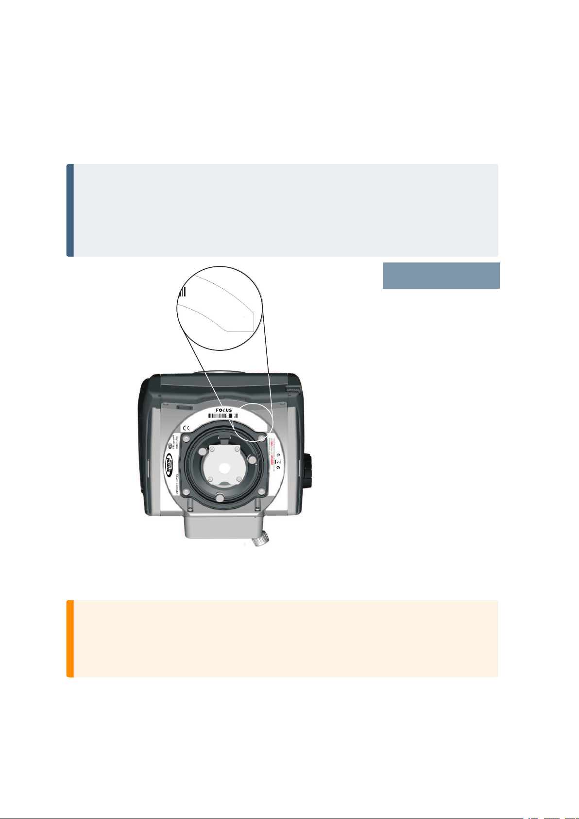
Instrument Versions
There are three different instrument types available: LockNGo™, RX, and Robotic. For more information
please read the Instrument Operational Methods. The instrument labels are on the bottom of the
instrument.
NOTE – Some specifications in this manual depend on the instrument revision. FOCUS 35 total
stations with the following part number prefixes match this manual exactly:
l Robotic part numbers beginning with "7853"
l RX part numbers beginning with "7855"
l LockNGo part numbers beginning with "7847"
Instrument types
FOCUS 35 Robotic 1''
FOCUS 35 Robotic 2"
FOCUS 35 Robotic 3"
FOCUS 35 Robotic 5"
FOCUS 35 RX 2"
FOCUS 35 RX 3"
FOCUS 35 RX 5"
FOCUS 35 LockNGo 1"
FOCUS 35 LockNGo 2"
FOCUS 35 LockNGo 3"
FOCUS 35 LockNGo 5"
Care and Maintenance
WARNING – Do not remove the instrument cover from the instrument.
A FOCUS 35 Total Station is designed to withstand normal electromagnetic disturbance from the
environment, but it contains circuits that are sensitive to static electricity. If an unauthorized
person opens the instrument cover, the function of the instrument is not guaranteed and the
warranty is invalidated.
The FOCUS 35 Total Station is designed and tested to withstand field conditions, but like all precision
instruments, it requires care and maintenance.
FOCUS 35 TotalStation User Guide | 18
Page 19

2 Inspection,Care, and Maintenance
Take the following steps to get the best results from the instrument:
l Do not subject the equipment to rough jolts or careless treatment.
l Keep the lenses and reflectors clean. Use only lens paper or other material that is designed for
cleaning optical equipment. A cleaner with a solution of pure water and 20-30% 2-Propanol
specified with evaporation residue <5mg/l is recommended.
l Keep the instrument protected and in an upright position, preferably in the instrument case.
l Do not carry the instrument while the instrument is mounted on a tripod. Doing so can damage the
tribrach screws.
l Do not carry the instrument by the telescope barrel, please use the handle.
l When you need extremely precise measurements, make sure that the instrument has adapted to
the surrounding temperature. Significant variations in instrument temperature can affect precision.
Cleaning
Be very careful when cleaning the instrument, especially when removing sand or dust from lenses and
reflectors. Never use a coarse cloth, a dirty cloth, or hard paper to clean the instrument. Spectra
Geospatial recommends that you use anti-static lens paper, a cotton wad, or a lens brush.
CAUTION – Never use strong detergents such as benzine or thinners on the instrument or the
instrument case.
Care of the Screens
Clean the screens with a dust-free cloth and gently wipe the screen. Use the provided dust-free cloth in
the screen protector package.
CAUTION – Do not use abrasive cleaners and do not apply any Cleaning Solution directly on the
screen.
FOCUS 35 TotalStation User Guide | 19
Page 20

2 Inspection,Care, and Maintenance
Applying a Screen Protector for the Face 1 Screen (if fitted)
Before applying a screen protector please read the screen protector installation guide/information
provided inside the screen protector package.
Use the screen protectors (ULTRA-Clear or ANTI-Glare) included in the instrument case to keep the
touchscreen clean and protected.
To apply a screen protector:
l Clean the display thoroughly with the provided dust-free cloth.
l Peel the backing from the screen protector.
l Align the edge, and then drop the remainder onto the display.
l Use the provided installation card, if necessary, to squeeze the air from underneath the screen
protector.
Ultra-Clear: Screen Protection with 99% visual transparency.
ANTI-Glare: Screen Protection with a perfect blend of anti-glare and optical clarity.
Removing Moisture
If the instrument has been used in damp weather, take the instrument indoors and remove the
instrument from the instrument case. Leave the instrument to dry naturally. If condensation forms on
the lenses, allow the moisture to evaporate naturally. Leave the carrying case open until all moisture has
evaporated.
Transporting the Instrument
Always transport the instrument in a locked instrument case. For longer trips, transport the instrument
in the instrument case and inside the original shipping container.
Servicing
NOTE – There are no user-serviceable parts on the FOCUS 35 Total Station.
Spectra Geospatial recommends that you take the instrument to an authorized service center for
service and calibration once a year. This is to guarantee that the specified accuracies are maintained.
When you send the instrument to a service center, clearly write the name of the sender and the receiver
on the instrument case. If repairs are required, enclose a note in the instrument case. The note should
clearly describe any fault or symptoms, and indicate that servicing is required.
FOCUS 35 TotalStation User Guide | 20
Page 21

Getting Started
Power Supply
Suspend Mode
Instrument Description
Optical Plummet
Trigger Key
Control Unit Face1 (if fitted)
Control Unit Face2
Telescope Lens rain cover / sun shade
3
Setting Up and Running ActiveSync technology
Troubleshooting Windows Mobile Device Center Connection Issues
Disconnecting ActiveSync
Laser Information
FOCUS 35 TotalStation User Guide | 21
Page 22

3 Getting Started
Power Supply
Before charging or using a battery it is important that you read and understand the battery safety and
environment information.
Battery Safety and Environment Information
WARNING – Do not damage the rechargeable Lithium-ion battery. A damaged battery can cause
an explosion or fire, and can result in personal injury and/or property damage. To prevent injury or
damage:
l Do not use or charge the battery if it appears to be damaged. Signs of damage include, but are
not limited to, discoloration, warping, and leaking battery fluid.
l Do not expose the battery to fire, high temperature, or direct sunlight.
l Do not immerse the battery in water.
l Do not use or store the battery inside a vehicle during hot weather.
l Do not drop or puncture the battery.
l Do not open the battery or short-circuit its contacts.
WARNING – Avoid contact with the rechargeable lithium-ion battery if it appears to be leaking.
Battery fluid is corrosive, and contact with it can result in personal injury and/or property damage.
To prevent injury or damage:
l If the battery leaks, avoid contact with the battery fluid.
l If the battery fluid gets into your eyes, immediately rinse your eyes with clean water and seek
medical attention. Do not rub your eyes!
l If battery fluid gets onto your skin or clothing, immediately use clean water to wash off the
battery fluid.
WARNING – Charge and use the rechargeable Lithium-ion battery only in strict accordance with
the instructions. Charging or using the battery in unauthorized equipment can cause an explosion
or fire, and can result in personal injury and/or equipment damage. To prevent injury or damage:
l Do not charge or use the battery if it appears to be damaged or leaking.
l Charge the lithium-ion battery only in a Spectra Geospatial product that is specified to charge
it. Be sure to follow all instructions that are provided with the battery charger.
l Discontinue charging a battery that gives off extreme heat or a burning odor.
l Use the battery only in Spectra Geospatial equipment that is specified to use it.
l Use the battery only for its intended use and according to the instructions in the product
documentation.
FOCUS 35 TotalStation User Guide | 22
Page 23
3 Getting Started
Battery Disposal
Before disposal, discharge the battery.
Dispose of the used battery in an environmentally sensitive manner, according to local and national
regulations, see also Environmental Information.
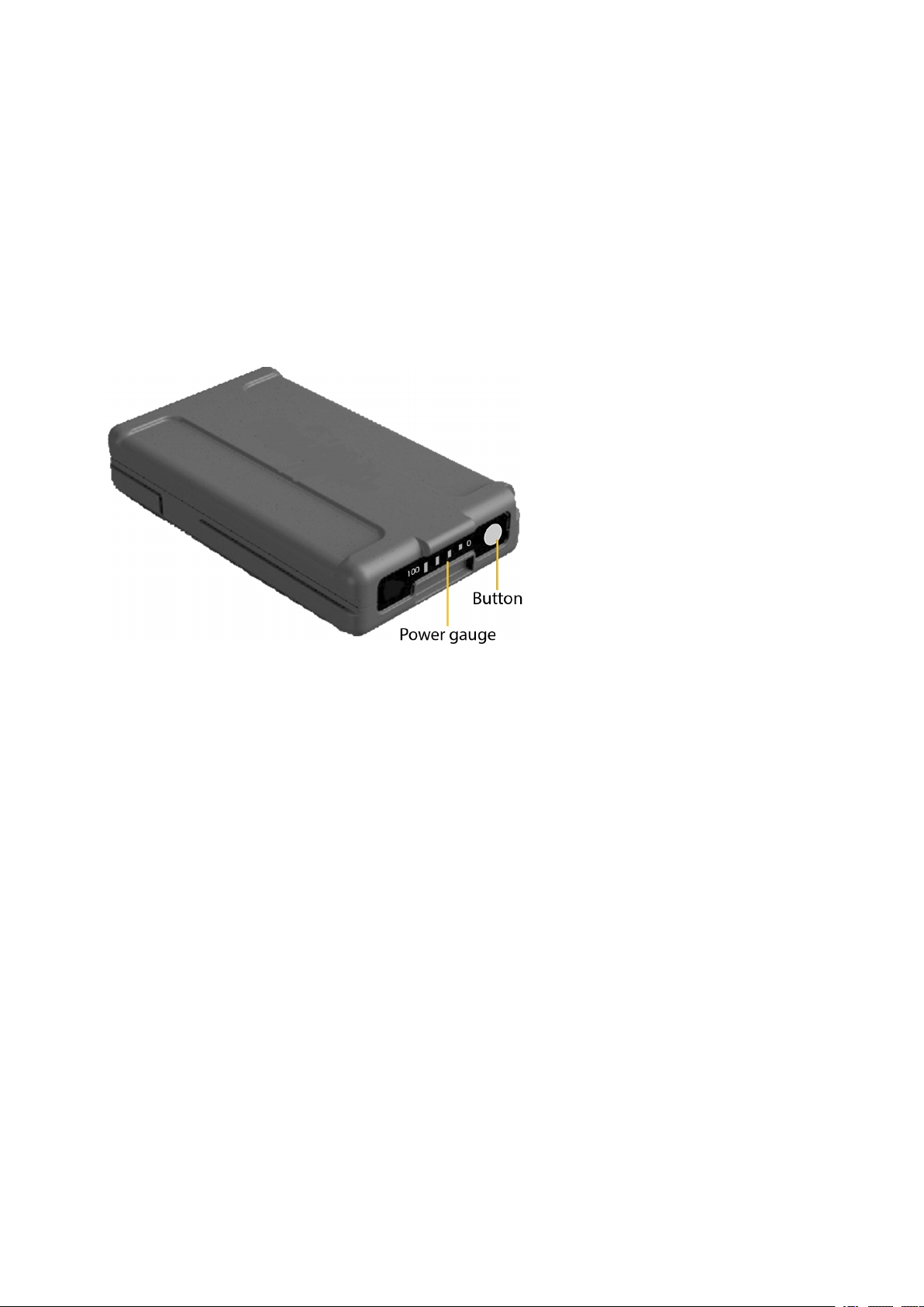
Checking the Instrument Battery Power Supply
To check the power supply in the FOCUS 35 Total Station battery using the built-in battery gauge, press
the button on the side of the battery:
When you press the button, four LEDs on the battery show the power level. Each LED corresponds to a
power level of 25% so that when the power level is at 100%, all four LEDs are lit. If the battery is
completely discharged, all LEDs are unlit.
When the button is pushed and all the LEDs flash, the battery needs to be reconditioned in the battery
charger.
When the battery capacity is between 0 and 10% one LED is flashing. A battery that has a flashing LED
might not be able to start the instrument. If started, with a battery that has a flashing LED, the operating
time will be between 5 and 15 minutes.
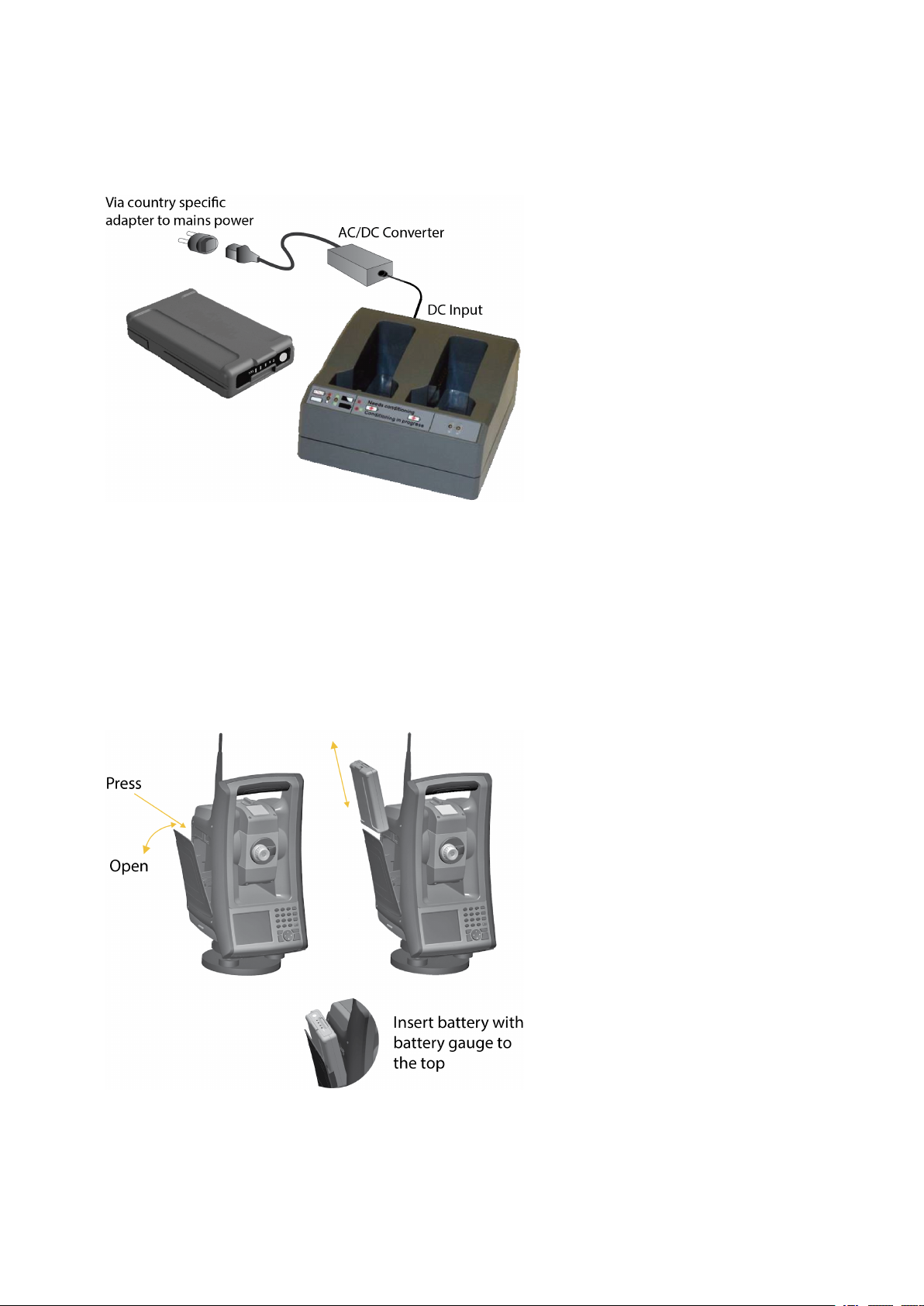
Charging the Instrument Batteries
The batteries are supplied partially charged. Charge the batteries completely before using it for the first
time.
l To charge the batteries, use only the charger that is recommended by Spectra Geospatial for
charging the lithium-ion battery. The charger can charge instrument and radio batteries. It can be
powered by mains power or from a car battery (socket / cigarette lighter adaptor). The charger can
be used either in car or office.
l Before charging the batteries please read the charger instruction information that was provided
with the charger package.
FOCUS 35 TotalStation User Guide | 23
Page 24
3 Getting Started
l Charge the battery before using the total station if the equipment has been stored for longer than
six months.
Inserting the Main Battery
The FOCUS 35 Total Station internal battery fits into the battery compartment on the side of the
instrument. This battery can easily be removed and replaced.
To insert the battery:
1. Press gently on the battery release button to open the battery compartment door.
2. Slide the battery into the battery compartment with the battery connectors positioned towards the
bottom of the instrument.
FOCUS 35 TotalStation User Guide | 24
Page 25
3 Getting Started
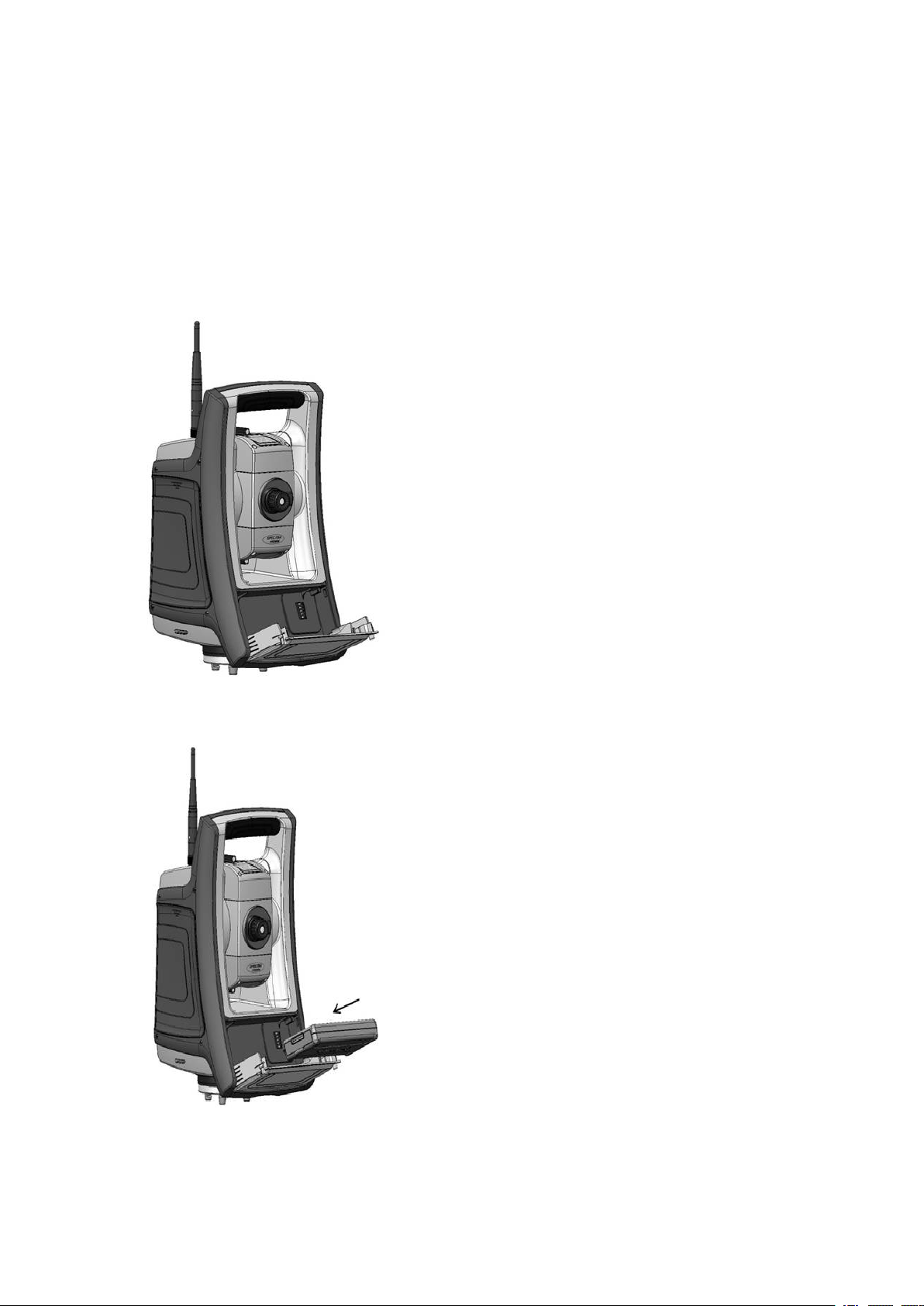
Inserting the Face 1 Battery (if Available)
On some FOCUS 35 Total Station models a second battery fits into the Face 1 battery compartment. This
battery can easily be removed and replaced.
To insert the battery:
1. Press gently on the two battery release buttons on either side of the compartment to open the
battery compartment door.
2. Slide the battery into the battery compartment door with the battery connectors positioned facing
upwards.
FOCUS 35 TotalStation User Guide | 25
Page 26
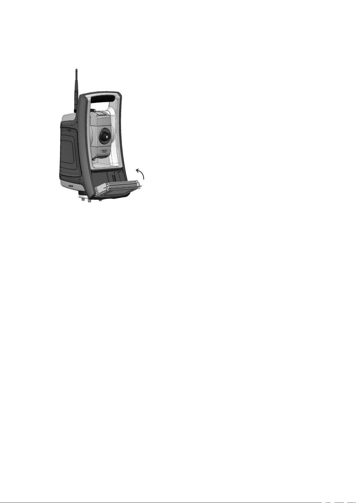
3 Getting Started
3. Close the battery compartment door, ensuring that both battery release buttons click into place.
Suspend Mode
The FOCUS 35 Total Station is equipped with an internal support module (support capacitor) that enables
you to suspend (“hotswap” or replace) the instrument battery within a period of 30 seconds from the
time you open the battery door.
To resume, press the power button for about one second, until you hear one single beep.
The internal support module is always charged when the instrument is powered on.
If you leave the FOCUS 35 Total Station idle, it goes into suspend mode after 120 minutes by default.
If the FOCUS 35 Total Station has not been restarted when the suspend period (default 120 minutes) has
elapsed, the instrument powers down and has to reboot when started again.
If the internal support module runs low on power the FOCUS 35 Total Station powers down sooner. Fully
charged and under normal conditions, the internal support battery should have capacity for about five
suspend sequences.
For more information please read Power Management, page 97.
FOCUS 35 TotalStation User Guide | 26
Page 27
3 Getting Started
Instrument Description
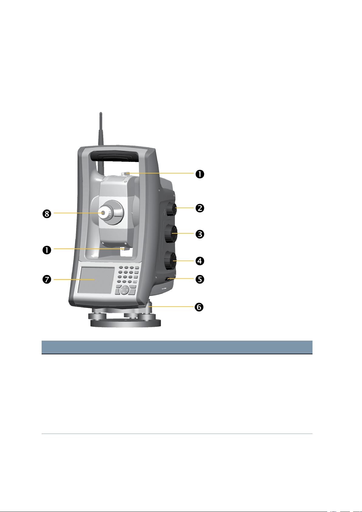
This section describes the instrument controls. Take some time to familiarize yourself with the names
and the locations of the controls.
The following image shows the Operator’s view of the FOCUS 35 Total Station.
Item Description
c
d
e
f
g
h
Coarse sight
Focusing servo knob
Vertical motion servo knob
Horizontal motion servo knob
On/Off and Trigger key
Stylus for touch screen
FOCUS 35 TotalStation User Guide | 27
Page 28
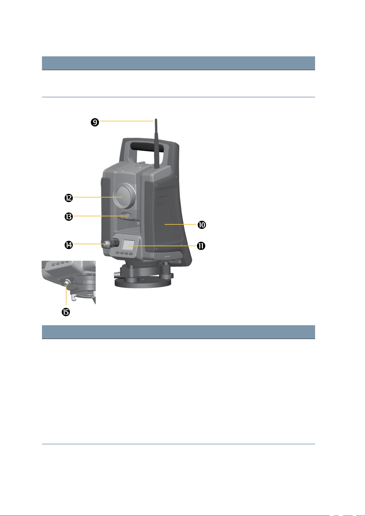
Item Description
3 Getting Started
i
j
The following is the Front view of the FOCUS 35 Total Station.
Face1 Control Unit or optional Face 1 Battery Compartment
Eyepiece
Item Description
k
l
m
n
o
p
q
Radio antenna
Radio antenna is not required in the LockNGo model.
Compartment for instrument battery
Face2 Control Unit
Optical plummet
Optics for tracklight
Coaxial optics for angle and distance measurements, tracker and laser pointer
Connector for both communication (COM) and power (12 V)
FOCUS 35 TotalStation User Guide | 28
Page 29
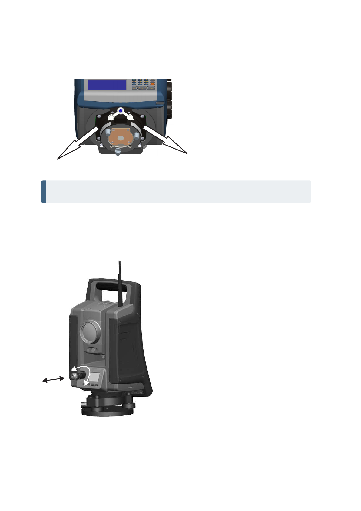
The following image shows the Connector Rubber Cap Placement.
NOTE – Please place the rubber cap in one of the shown directions. Another orientation will limit
the function to insert instrument into tribrach or to turn the instrument.
3 Getting Started
Optical Plummet
The instrument is equipped with an optical plummet, which has 2x magnification and a focusing range of
0.5 m (1.6 ft) to infinity. The instrument can be positioned to an accuracy of 0.5 mm (0.02 in) at 1.5 m (49
ft) over a ground mark.
FOCUS 35 TotalStation User Guide | 29
Page 30
3 Getting Started
l To focus the crosshair, rotate the eye-piece.
l To focus the optical plummet to the ground, push in or pull out the optical plummet.
For information on how to adjust the optical plummet, see Optical Plummet, page 77.
Trigger Key
The trigger key functions as an On/Off key (z). A LED in the trigger key indicates if the instrument
is turned on. A solid light indicates On and a flashing light indicates Suspend Mode and waiting for
connection, see also Power Management.
When a field application is running, the trigger key performs the same function as the Measurement1 key
(M) on the Face1 side and the Enter key (P) at the Face2 side.
Keys Description
M z P
L
Measurement1 - definable
Measurement2 - reflectorless measurement and recording
(Except the measurements in QuickShot menu without open job)
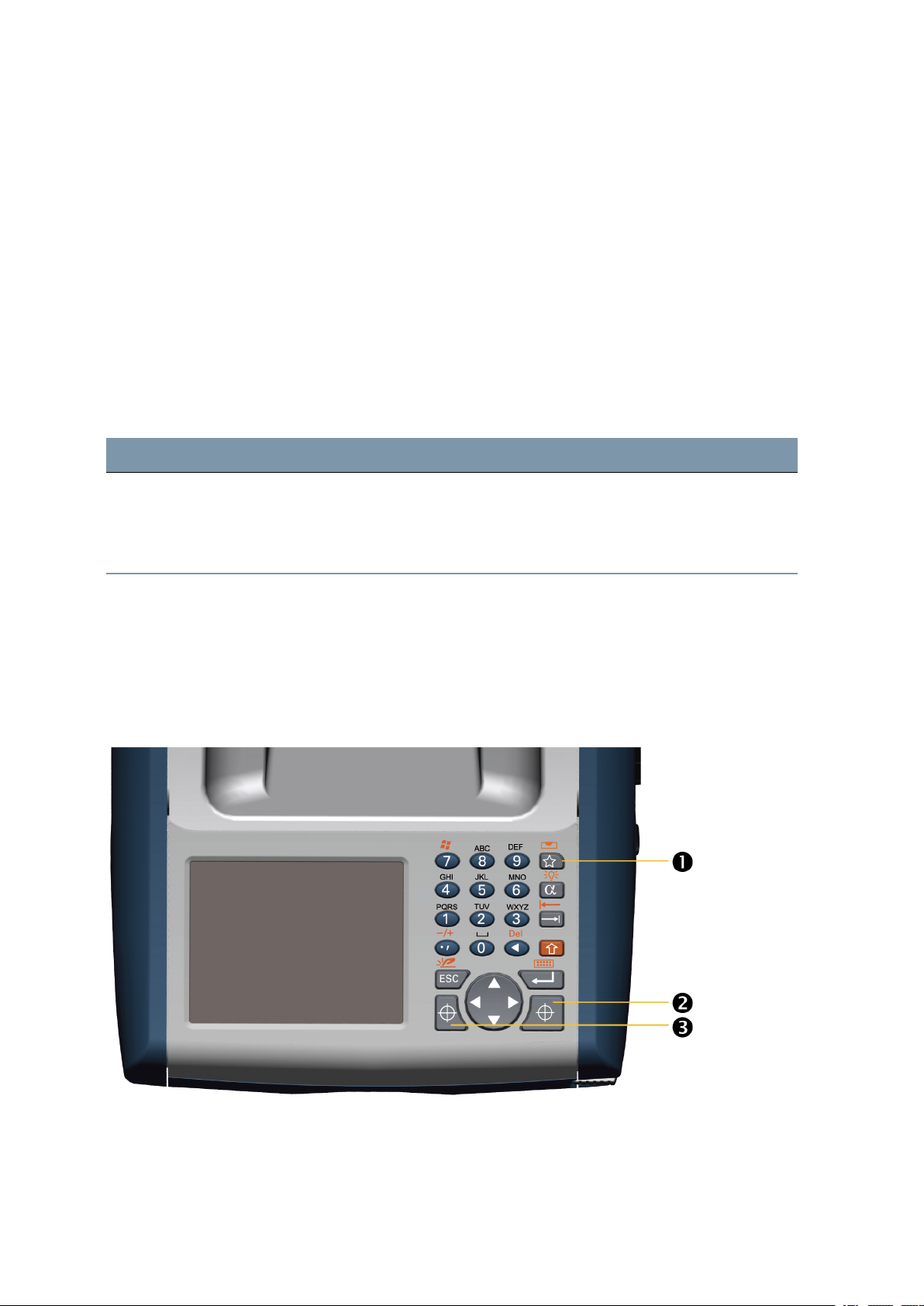
Control Unit Face1 (if fitted)
Data entry on the keyboard is similar to that of a mobile phone. The “A” button scrolls between three
different states of data entry: 123, ABC, and abc. Multiple presses on one key scrolls through the letters
on that key depending on which mode is currently selected.
The image shows the Control Unit Face1.
FOCUS 35 TotalStation User Guide | 30
Page 31

Item Description
3 Getting Started
❶
❷
❸
Quick Shot Menu
Measurement 1
Measurement 2
Control Functions Control Unit Face1
In addition to data entry and the standard Microsoft® Windows® operating system functions, the Control
Unit has a number of control functions that are Spectra Geospatial specific. These functions are
described in the table below.
Keys Function Description
M
L
R
T+A
T+B
C Toggle the backlight on/off
K Disable/enable the touch screen
Measurement1 (in field software only)
Measurement2 (in field software only)
Quick Shot Menu (in field software only)
T
+
S Toggle the touch screen keyboard on/off
Q
T+R
T+7
T+,
T+E
I Switch to level bubble - in field software only
Z Pop up the Windows taskbar
+ Enter a “-” or a “+” symbol
Y Delete
Operating System
The FOCUS 35 Total Station runs the Windows CE .Net operating system.
Data Storage
The FOCUS 35 Total Station has two kinds of memory:
l 512 MB RAM
RAM is volatile, and you risk losing data if the power fails.
l 4 GB NAND flash storage memory
FOCUS 35 TotalStation User Guide | 31
Page 32
3 Getting Started
The NAND flash storage memory is non-volatile, and protects valuable data and software against
memory loss.
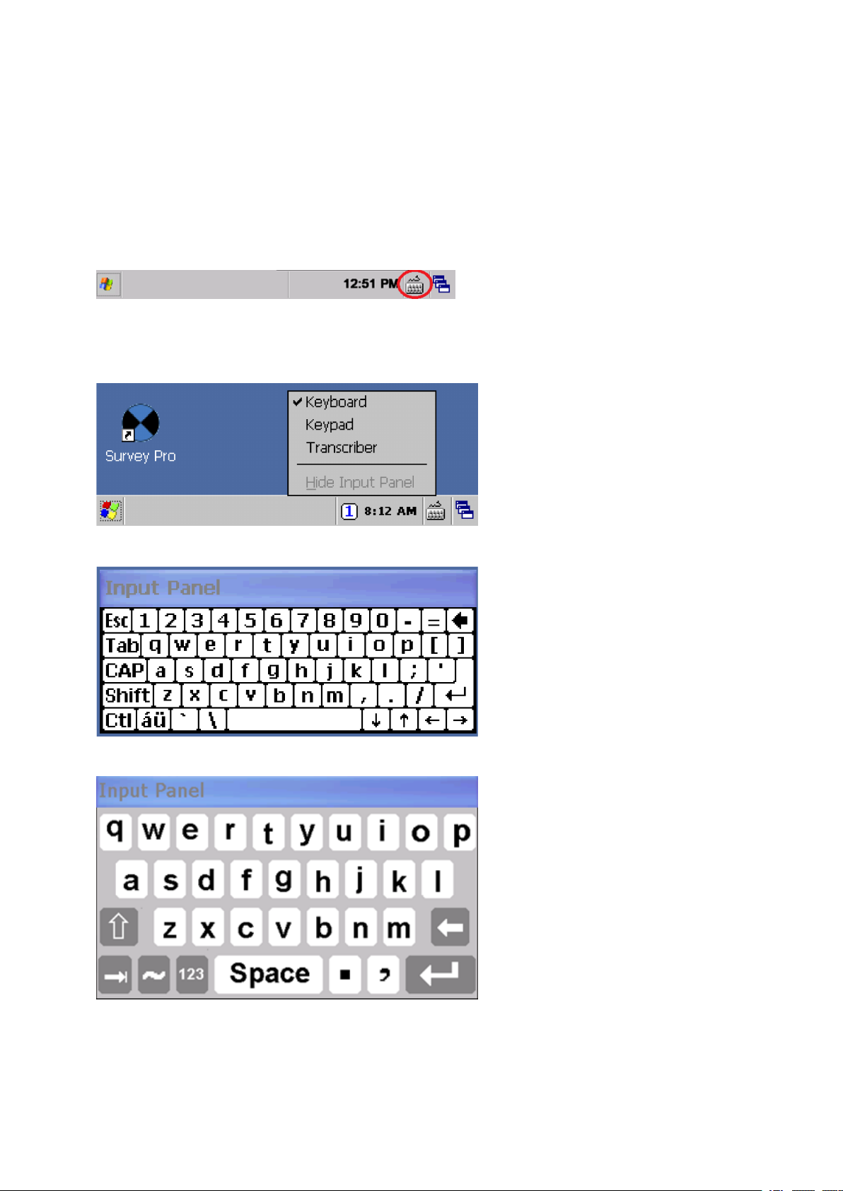
Entering Information
Tap once on the Input Panel icon that is located in the Windows CE Taskbar. The icon is selection
related.
Input Panel menu
The Input options are Keyboard or Survey Keyboard:
Keyboard — allows you to input data as if you were typing on a physical keyboard
Survey Keyboard — has larger keys than the keyboard
FOCUS 35 TotalStation User Guide | 32
Page 33

3 Getting Started
Touch Screen
The LCD screen in Face1 can be viewed easily both in direct sunlight and in overcast conditions. It also
incorporates a touch interface for navigation. Tap elements on the screen with a stylus or your finger.
Calibrating the Touch Screen
If the touch screen does not respond properly when you tap it, recalibrate it as follows:
Tap the Start menu and select Settings / Control Panel / Stylus. The Stylus Properties appears.
To recalibrate, tap Recalibrate in the Calibration tab.
Follow the prompts on the screen.
Disabling the Touch Screen
To clean the touch screen during a survey, press T + B [S] to disable it. To enable the touch
screen again, press T + B.
Display Backlight Face1 Control Unit
The display light is active by default and can be toggled on/off by pressing T + A [C]. To change
backlight brightness and save battery life
Tap the Start menu and then select Settings / Control Panel / Display Properties / Backlight.
Adjust Backlight brightness and select when the instrument has to turn off the backlight automatically.
Tap OK.
NOTE – Settings for display light Face2 and reticle illumination see Settings Face2 Display
Backlight, Reticle Illumination and Tracklight.
Settings Time and Date
Tap Start menu and then select Settings / Control Panel / Date / Time.
Change the date and time as required.
To accept the new settings, tap OK. To cancel, tap B.
NOTE – When you attach the instrument to your computer using Microsoft® ActiveSync®
technology, the time and date are automatically updated.
FOCUS 35 TotalStation User Guide | 33
Page 34

Control Unit Face2
The Face2 control unit is a graphical display with a built-in backlight and four control buttons.
Function Description
3 Getting Started
U
N
O
P
When a secondary function is available for the keys (N,O or P), an icon appears at the bottom of
the display. To access the secondary function, press the appropriate key.
A long press with the key U starts the Control Unit Face2 Backlight. Without any actions Backlight
turns off after 30 seconds.
NOTE – When the field software is running, the trigger key performs the same function as the
Measurement1 key (M) on the Face1 side and the Enter key (P) at the Face2 side.
Change Face
Scroll Up
Scroll Down
Enter
FOCUS 35 TotalStation User Guide | 34
Page 35
3 Getting Started
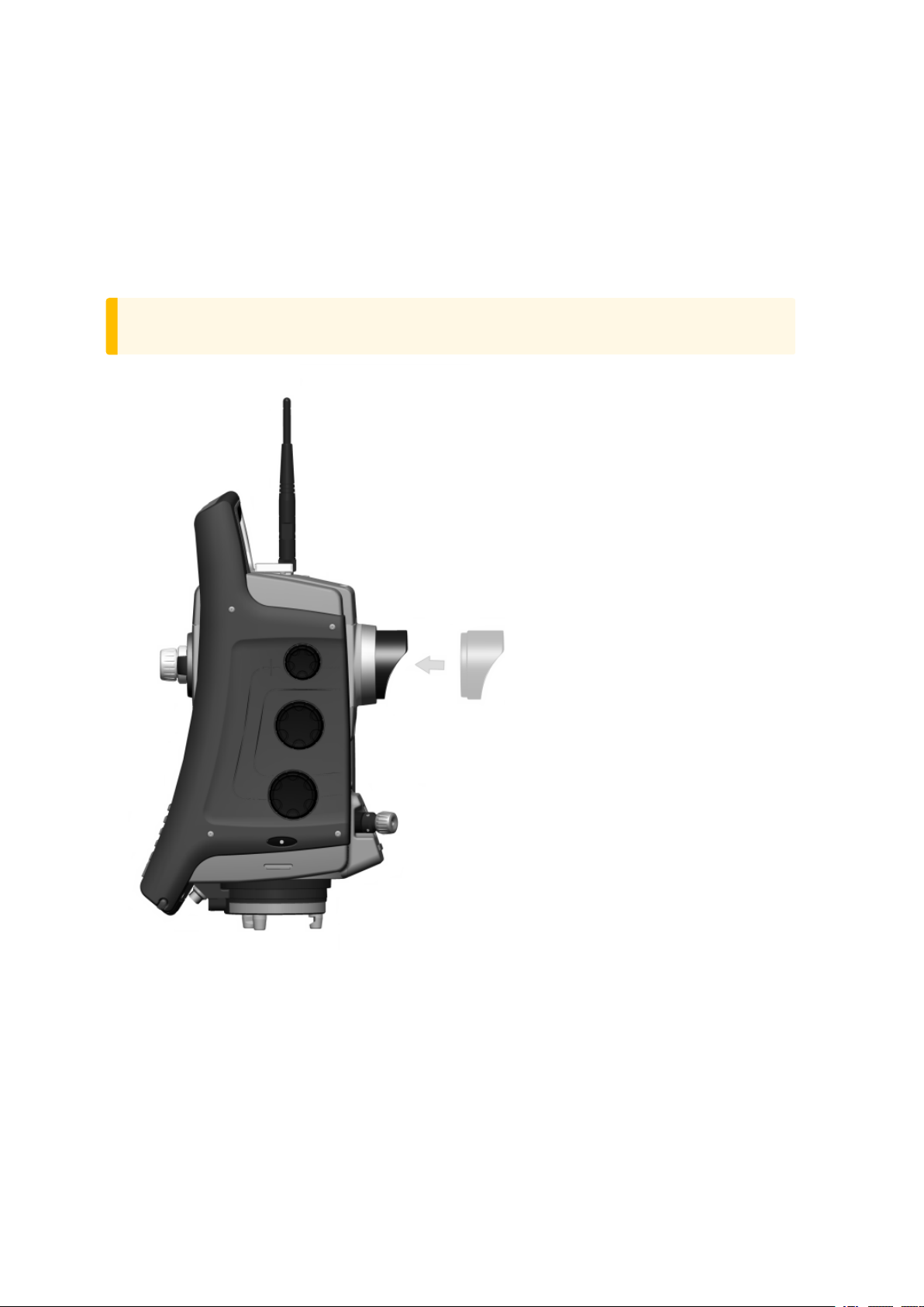
Telescope Lens rain cover / sun shade
The Telescope Lens rain cover / sun shade protects the objective lens surface while measuring in drizzle
or lighter rain. The cover works in one Face only. The rubber material prevents damage to the internal
instrument system itself while unintentional moving between the two faces.
Fit the objective rain cover to the Face1 side of the instrument with the shield at the top of the objective.
CAUTION – Dust and rain can have an effect on the distance measurements, please keep
objective front lens and the targeting prism clean and use the objective rain cover.
FOCUS 35 TotalStation User Guide | 35
Page 36

3 Getting Started
Connecting the Instrument to an Office Computer
Transferring Data Files
Microsoft ActiveSync technology and WindowsMobile® Device Center (WMDC) provide an easy way to
synchronize data on a Windows-based computer with your FOCUS 35 Total Station. WMDC works only on
computers that have the Windows Vista® or Windows 7 operating system. Windows 10 version 1703 and
later have been found to have issues running Windows Mobile Device Center (WMDC). For more
information, please see Troubleshooting Windows Mobile Device Center Connection Issues.
ActiveSync and WMDC act as gateways between your device and your computer for transferring data.
You can also use the Explore feature in either program to move files or programs from your computer to
your device.
ActiveSync is already integrated into the operating system on the FOCUS 35 Total Station. However, you
must install ActiveSync or WMDC depending on your computers operating system. To download the
current version:
l ActiveSync technology: www.microsoft.com/en-us/download/details.aspx?id=15
l Windows Mobile Device Center: www.microsoft.com/en-us/download/details.aspx?id=14
There are two types of ActiveSync connections. The table below summarizes the advantages and
disadvantages of each choice.
Advantages Disadvantages
Guest Fewer questions to answer on initial
connection.
Safer because synchronization
cannot adversely impact data
Slower subsequent connections (one more step
per connection that requests Partnership).
You have to arrange these settings with every
new instrument connection.
either on the instrument or the
computer.
Partnership Fast subsequent connections (one
More questions to answer on initial connection.
fewer step per connection).
The clock on the instrument is set
to match the computer clock.
If the clock on the computer is wrong, it will
incorrectly set the clock on the instrument.
Partnership is deleted when the instrument is
hard reset.
FOCUS 35 TotalStation User Guide | 36
Page 37
3 Getting Started
Setting Up and Running ActiveSync technology
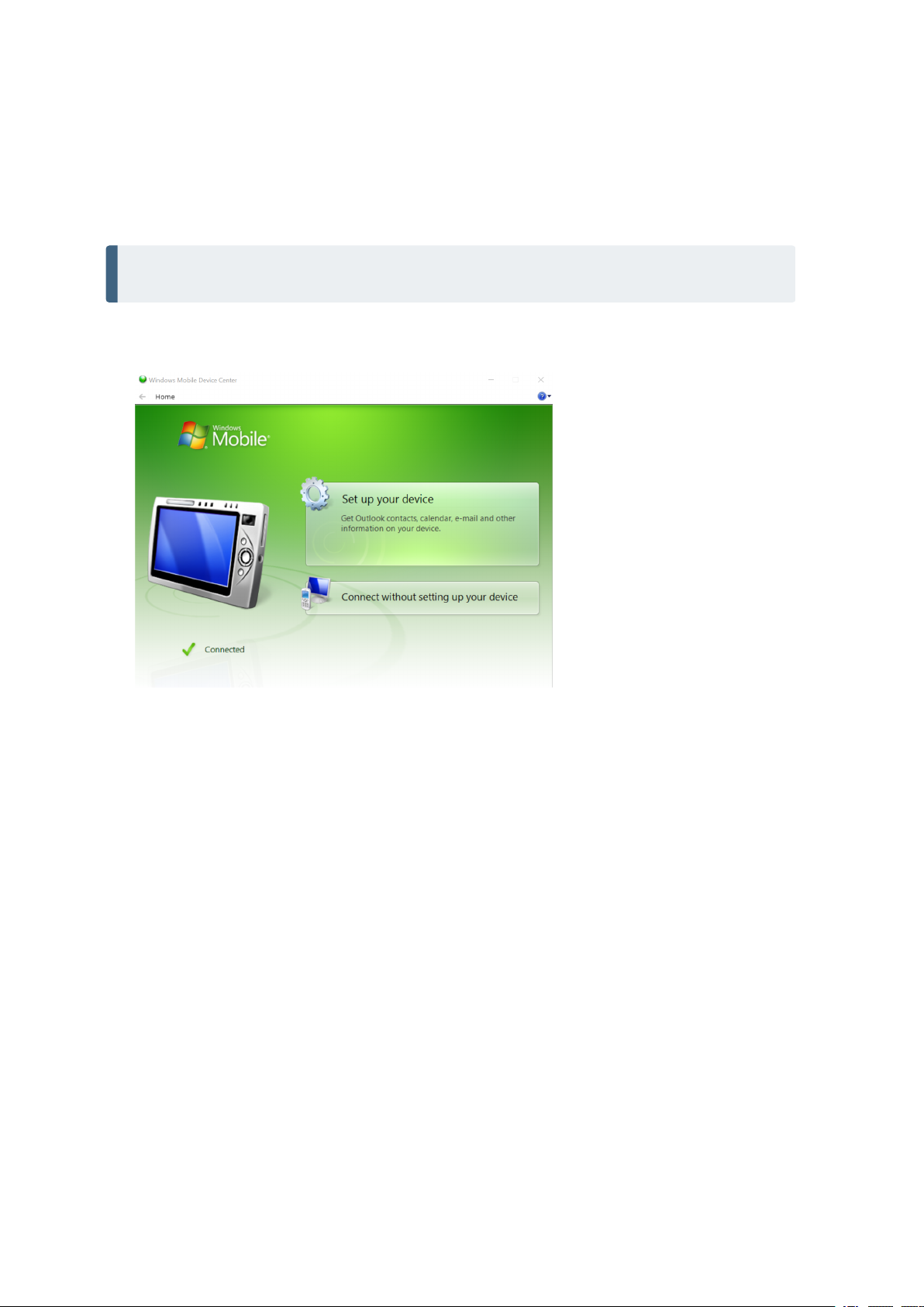
Please use the Hirose-USB cable to connect the FOCUS 35 Total Station with a USB port of your
computer. The instrument will switch on automatically.
NOTE – Microsoft ActiveSync technology or the Windows Mobile Device Center will start
automatically, depending on the operating system that is installed on your computer.
Do the following:
1. Program ActiveSync starts automatically.
2. If you select Connect without setting up your device, you are set up as a guest and the dialog does
not appear asking which items to synchronize. Go to Enter the device name and click Set Up. The
Home screen appears:.
FOCUS 35 TotalStation User Guide | 37
Page 38
3 Getting Started
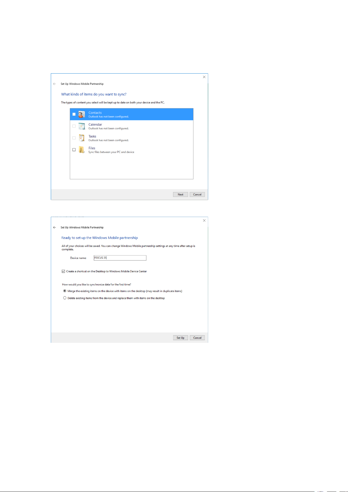
3. If you select Set up your device, Spectra Geospatial recommends that you clear all the check boxes
in the next dialog.
4. Click Next to continue.
FOCUS 35 TotalStation User Guide | 38
Page 39
3 Getting Started
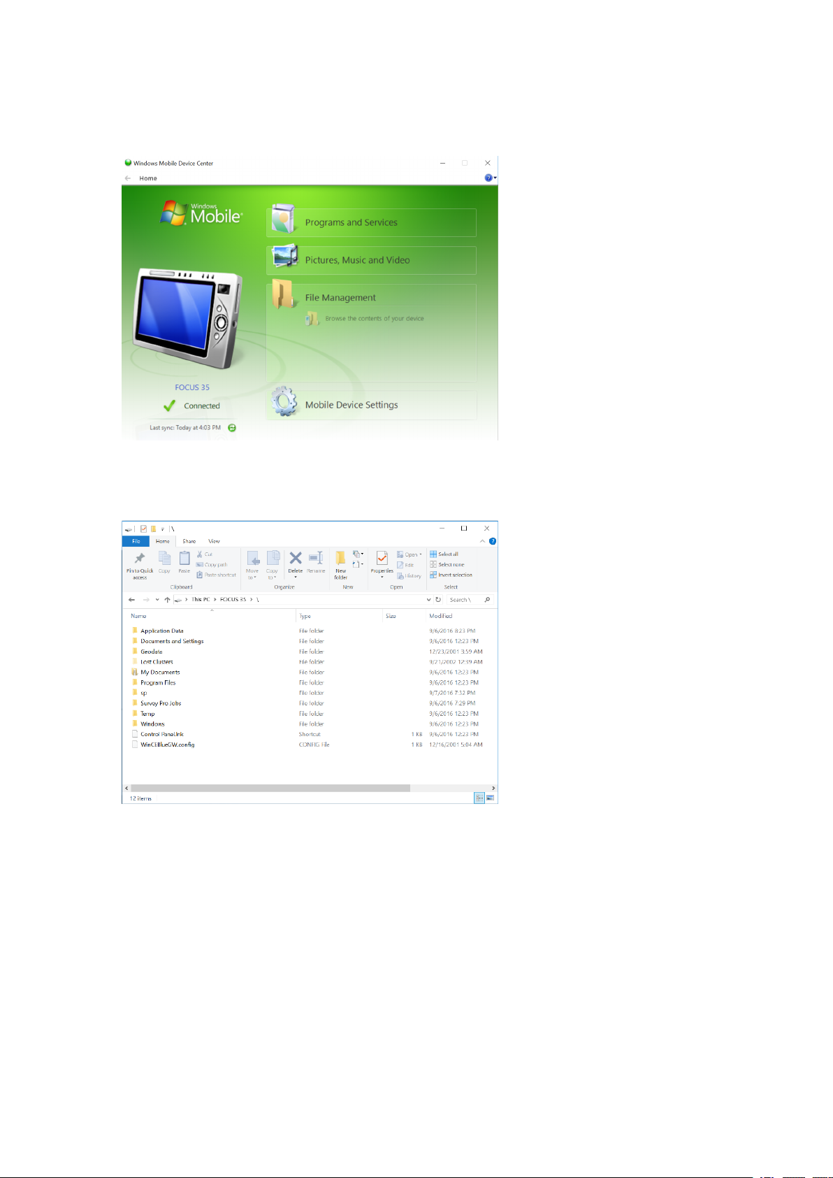
5. Enter the device name and click Set Up. The Home screen appears:
6. To view the files on the Instrument, click the File Management icon, then click Browse the contents
of your device. The file structure looks and functions the same as Windows Explorer on your
computer:
FOCUS 35 TotalStation User Guide | 39
Page 40

3 Getting Started
Troubleshooting Windows Mobile Device Center Connection Issues
Microsoft ended support for the Windows Mobile® Device Center (WMDC) in 2012; the latest Microsoft PC
operating systems are not designed to be compatible with WMDC. WMDC may not work with Windows® 10
version 1703, or any subsequent Windows 10 versions. The following options may help WMDC start working
again:
Install and enable .NET Framework 3.5
Sometimes before successfully installing WMDC, you must enable the required .NET Framework 3.5. This
can be done from inside the control panel, or by running a previous framework installer from Microsoft.
Option 1: Enable .NET Framework 3.5 within the control panel:
1. Navigate to Control Panel / Programs / Programs and Features / Turn Windows features on or
off.
2. Select the .NET Framework 3.5 check box.
Option 2: Enable .NET Framework 3.5 by running a previous framework installer from Microsoft:
1. Download the Microsoft Windows Mobile Device Center 6.1 Driver for Windows Vista directly from
www.microsoft.com, selecting either the 32- or 64-bit version that is appropriate for your computer.
2. If WMDC and the required drivers do not successfully install automatically through the Windows
Update service when you connect to USB, run the installer as an administrator and in Compatibility
Mode for Windows Vista.
Registry Changes
After installation and once the Windows Mobile Device Center appears in the product list under the Start
menu on the desktop PC, you may need to add the following registry entries, and then perform a restart
of the computer:
l HKLM\SYSTEM\CurrentControlSet\Services\RapiMgr\SvcHostSplitDisable = 1
l HKLM\SYSTEM\CurrentControlSet\Services\WcesComm\SvcHostSplitDisable =1
These registry entries change the way the operating system handles the background processes
(services) that control WMDC connectivity. The handling of background services changed in Windows 10
version 1703 and these additions allow WMDC to continue to work.
A PC application tool that will add these registry settings is available to simplify the registry editing
process.
1. Download the Registry Editing Tool from Trimble:
http://trl.trimble.com/dscgi/ds.py/Get/File-848877/WMDCRegistryUpdate.exe
2. From the File Explorer, right-click the file and choose Run as Administrator.
The tool must be run with Administrator privileges because it modifies the computer's registry.
FOCUS 35 TotalStation User Guide | 40
Page 41
3 Getting Started
3. A pop-up confirms the tool is from Trimble and asks for confirmation to run; choose Yes.
4. A command window opens and displays the changed registry values. Press any key to exit the
application once it is complete.
Disconnecting ActiveSync
CAUTION – To avoid disconnection problems, close ActiveSync before removing the cable. Next
remove the cable from the computer and then the cable from the instrument.
To disconnect ActiveSync:
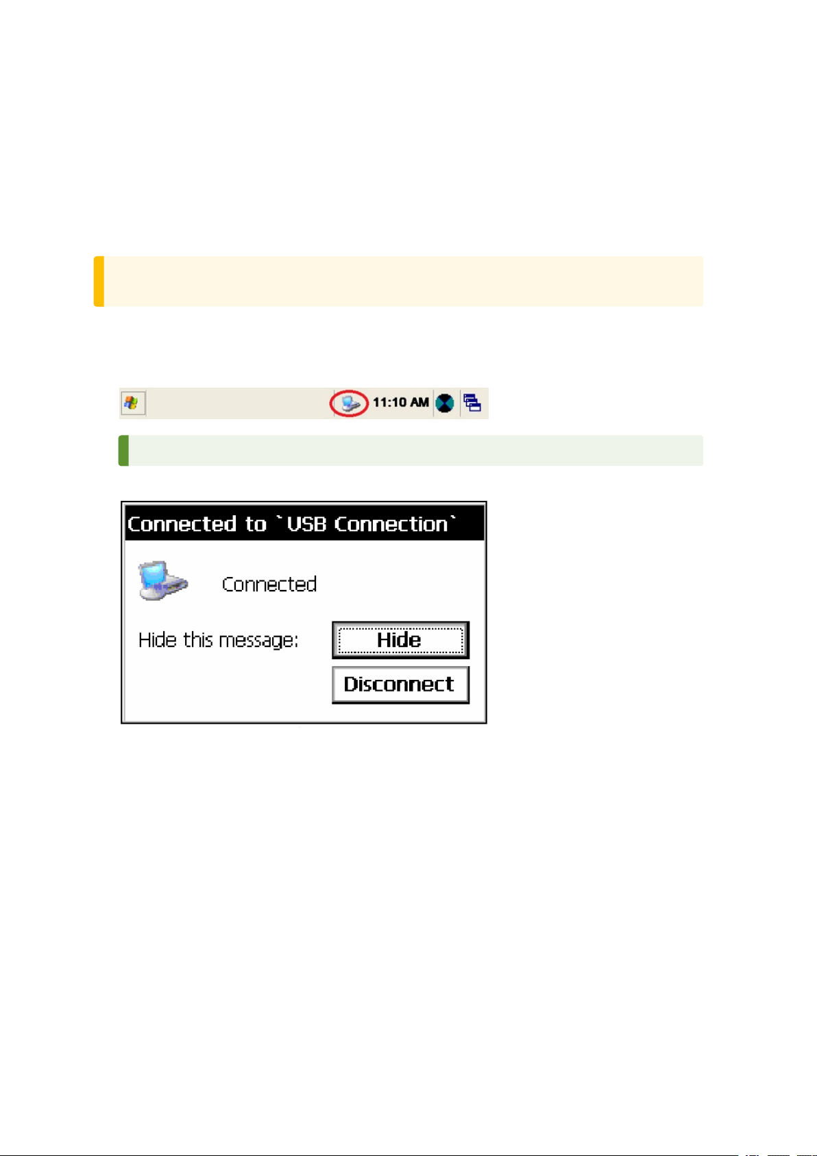
1. Double-tap the connection icon in the task bar at the bottom of the screen, see image below for
location of icon.
TIP – You have to wait a few seconds until the next screen appears.
2. Tap Disconnect and then remove the cable:
For more information about ActiveSync, refer to the help or visit the Microsoft website.
Laser Information
For more information, see Laser Safety, page 4.
FOCUS 35 TotalStation User Guide | 41
Page 42
3 Getting Started
FOCUS 35 Total Station
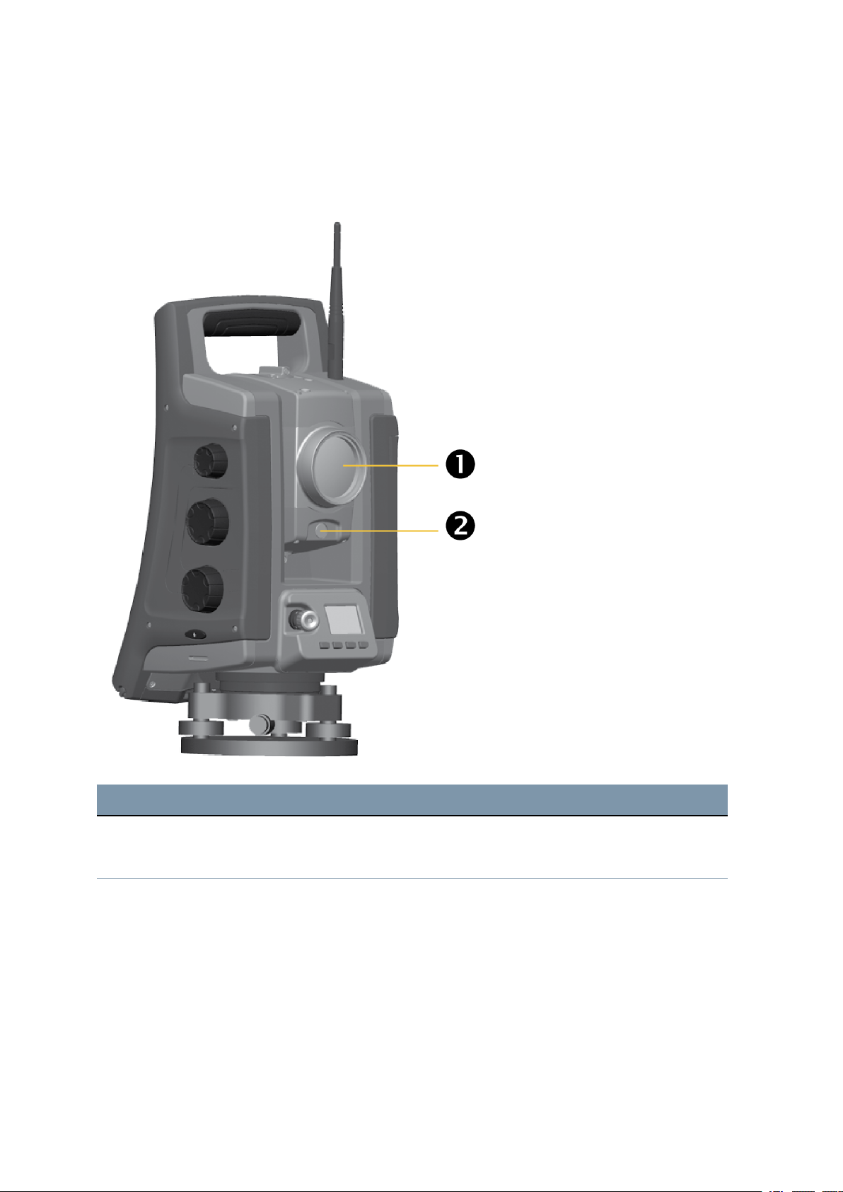
The FOCUS 35 distance measuring unit and Laser Pointer has been tested and complies with the
regulations for a CLASS 3R LASER PRODUCT.
Item Description
❶
❷
Distance measurement LockNGo and Laser pointer aperture
Tracklight aperture
FOCUS 35 TotalStation User Guide | 42
Page 43
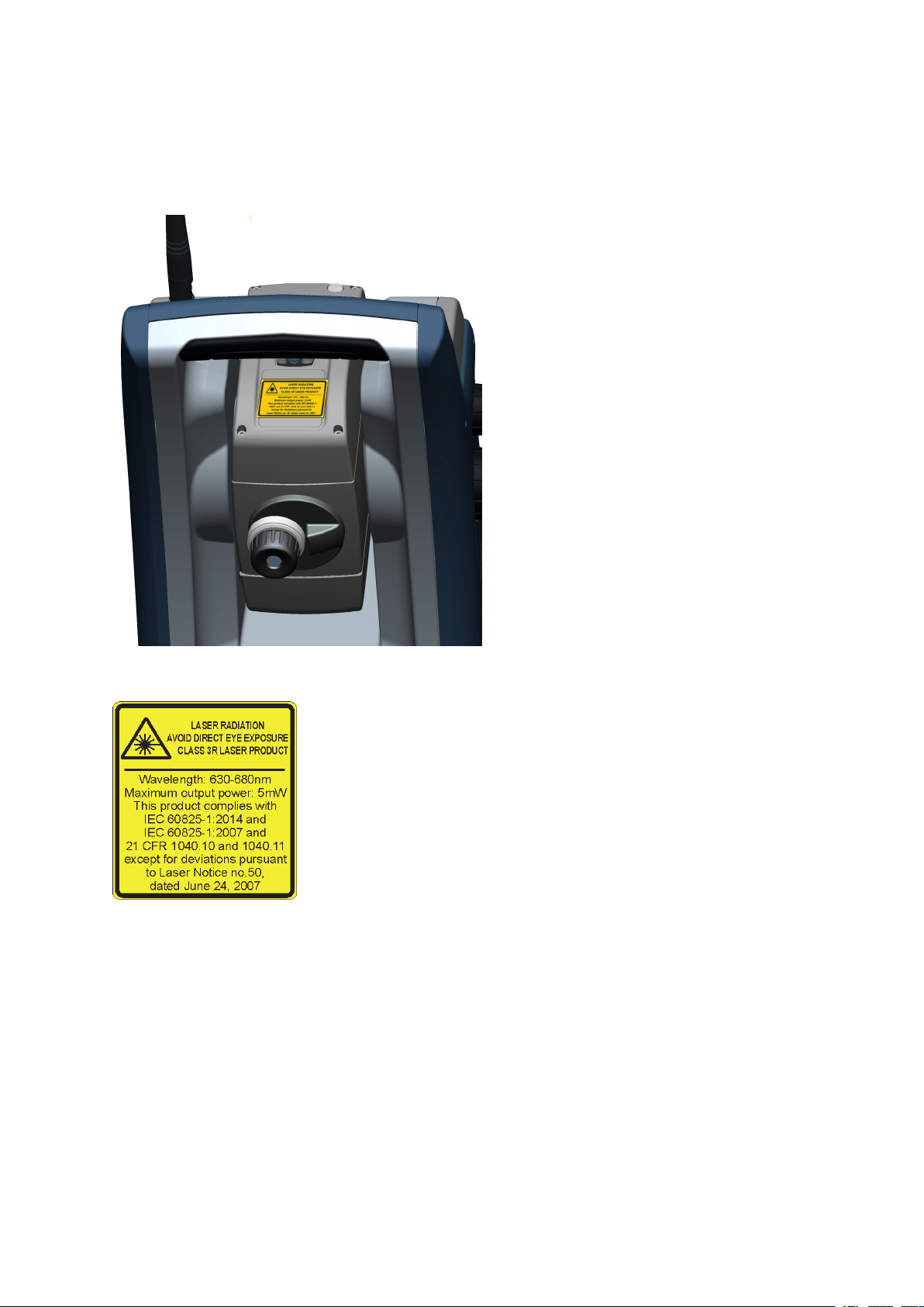
Location of Laser warning label on a FOCUS 35 Total Station
The laser warning label is located on the top of the distance measuring unit.
3 Getting Started
Distance Measurement Unit and Laser Pointer warning label:
FOCUS 35 TotalStation User Guide | 43
Page 44
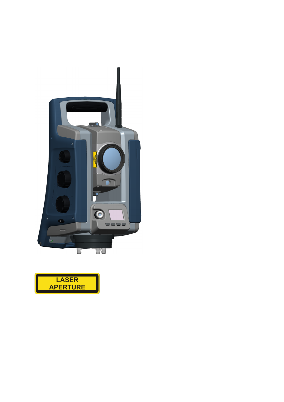
Location of Laser aperture label on a FOCUS 35 Total Station
The laser aperture label is located on one side of the telescope close to the objective.
3 Getting Started
Laser aperture label:
FOCUS 35 TotalStation User Guide | 44
Page 45

Setup
Setup
Starting the Instrument
Security
Face2 Display while using the Survey Pro Software in different Instrument Versions
Instrument Adjustment and Calibration
LockNGo Tracker
Measuring the Instrument Height
Pre Measurement Check List
4
Connecting to an External Data Collector
FOCUS 35 TotalStation User Guide | 45
Page 46
4 Setup
Setup
An instrument setup with good measuring stability will increase the precision in the measurement result
and allow you to utilize the measurement precision of the FOCUS 35 Total Station to its full extent.
Setup Stability
When an instrument is setup it is important to consider the following:
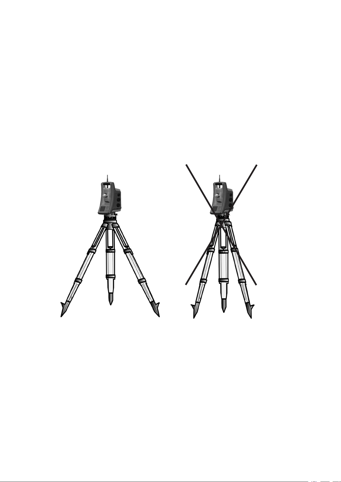
1. Set tripod legs wide apart to increase the stability of the setup. A setup where one leg is placed on,
for example, asphalt and the other two on soil will still be a stable setup provided that the tripod legs
are set wide enough apart. If it is not possible to set the tripod legs wide apart due to obstacles, then
the tripod can be lowered to increase stability.
2. Make sure that all the screws on the tripod and/or tribrach are tightened to avoid any play.
3. Any high quality tripod and tribrach can be used. However, Spectra Geospatial strongly recommends
the use of tripod heads made of steel, aluminum or similar material. Tripod heads of fiberglass or
other composite materials are not recommended.
See also StepDrive Motor System and Focus System, page 94 for more information.
FOCUS 35 TotalStation User Guide | 46
Page 47
4 Setup
Measurement Stability
Take into account that instruments require sufficient time to adjust to the ambient temperature. The
following rule-of-thumb for a high precision measurement applies: Temperature difference in degree
Celsius (°C) x 2 = duration in minutes required for the instrument to adjust to the new temperature.
Avoid sighting across fields with intense heat shimmer by sun light, e.g., at noon.
Starting the Instrument
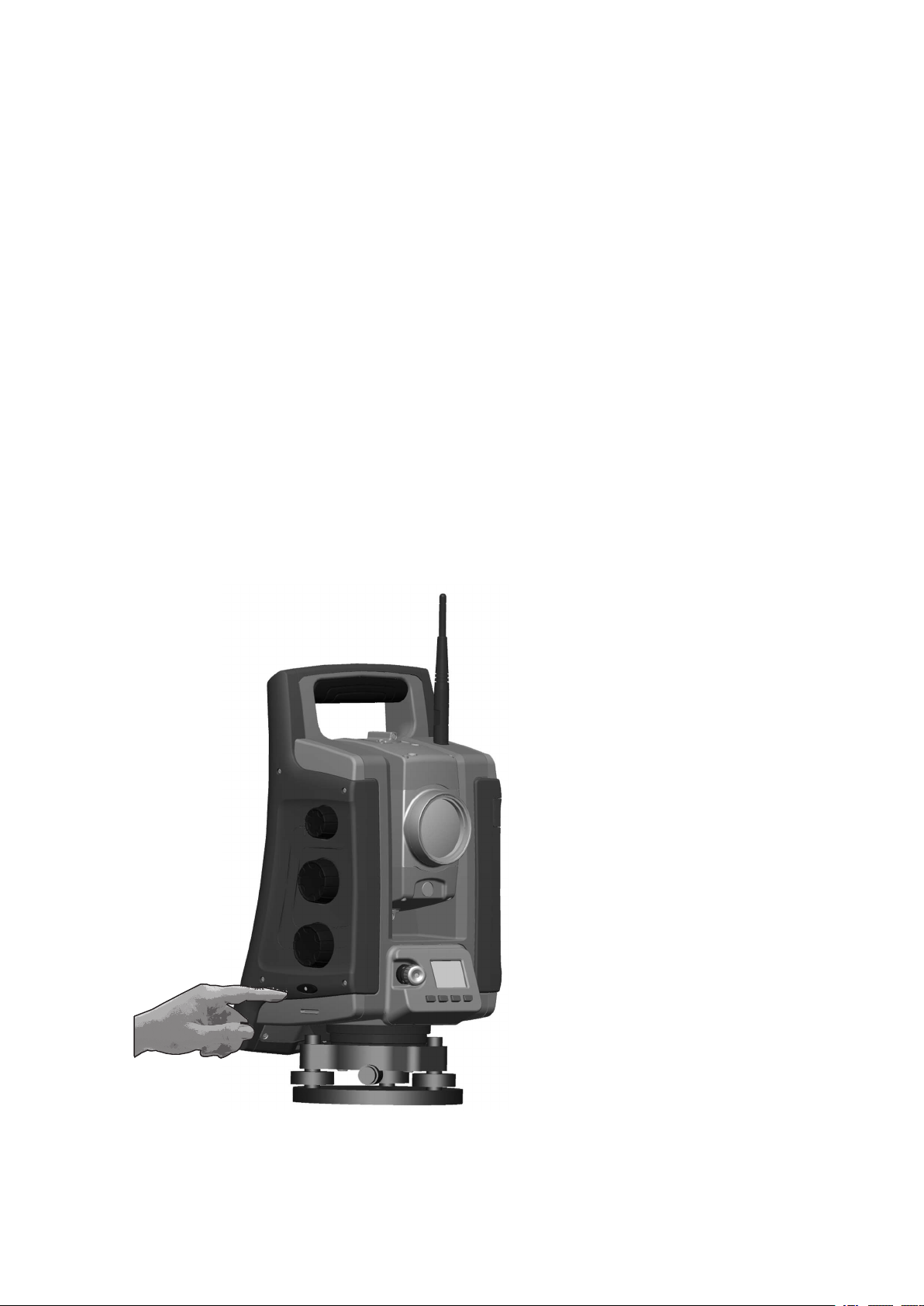
To start the instrument please press the on/off button about 1 second (one single beep) on right side of
the instrument. This will also start the Windows CE operating system.
This section describes sequentially how different settings can be done in the field software in Face1
Control Unit as well as in the Face2 Control Unit.
l The settings in the Face2 interface are accessible only without starting the field software. It is
recommended especially if you want to work in Robotic mode.
l When the Windows CE operating system starts, select your field software from the start menu.
Please refer to your Survey field application documentation for supplementary information.
FOCUS 35 TotalStation User Guide | 47
Page 48
Starting and Settings via Face1 Control Unit (if fitted)
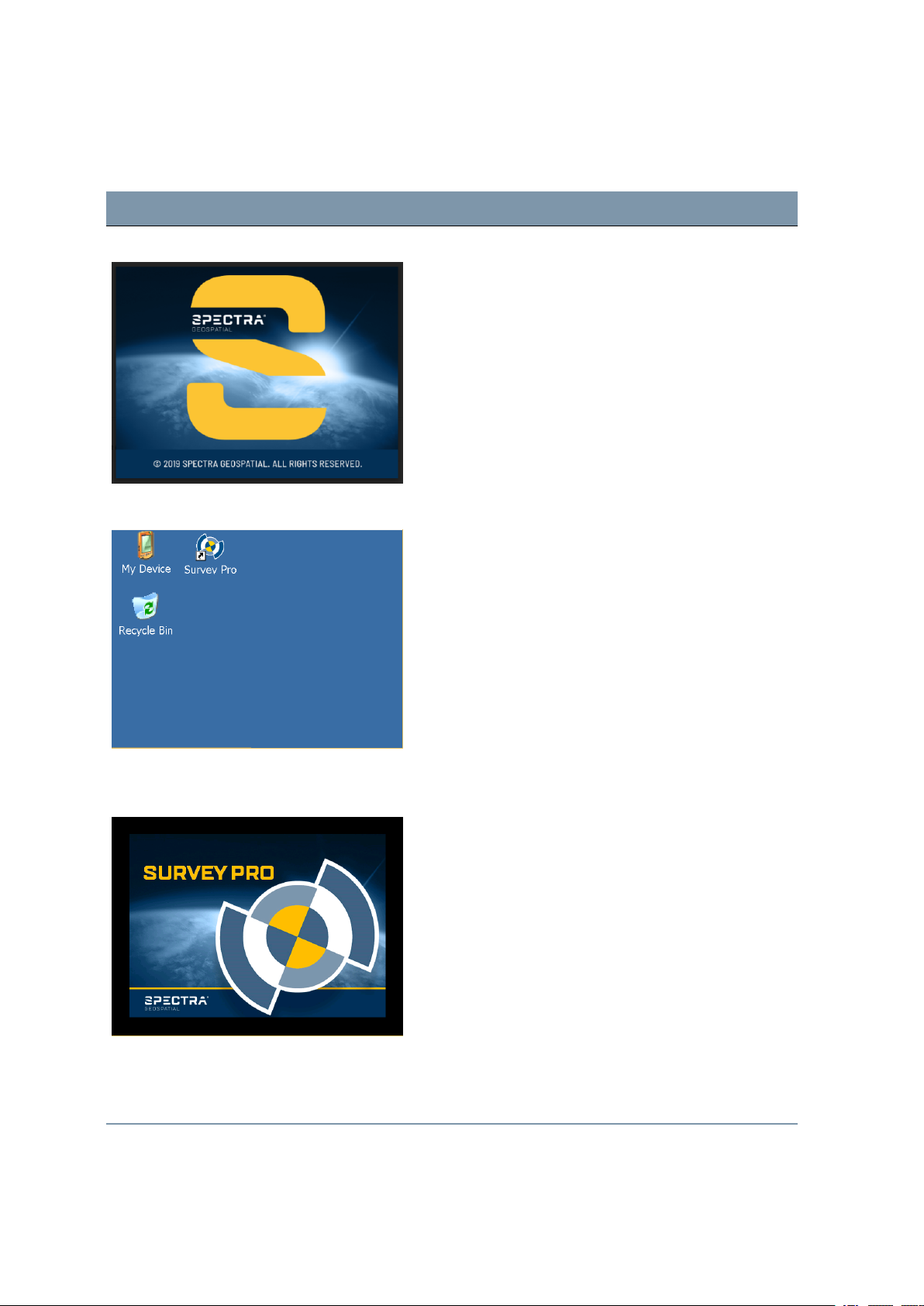
Screen Actions and Comments
Face1 screen after instrument start While starting Windows CE the SpectraGeospatial logo
screen will show for several seconds and then the menu
to work in Windows CE will appear.
Face1 screen after starting Windows CE Start the Survey Pro™ software by tapping the Survey
Pro icon.
4 Setup
Face1 screen while starting the Survey Pro
software
NOTE – StepDrive motor system and Focus System are
already usable at this phase.
NOTE – If you are using the Layout Pro™ software, refer
to the User Guide for information on using the FOCUS 35
total station.
Instrument loads the Survey Pro software.
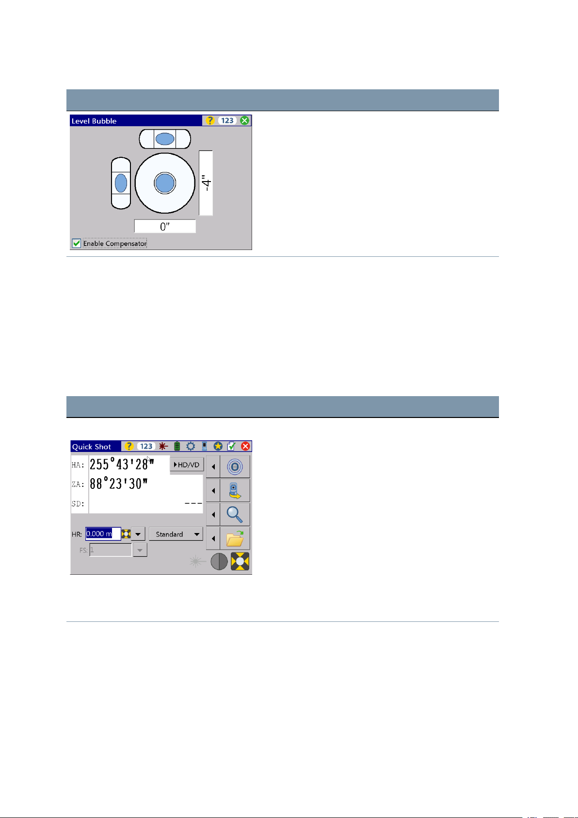
Electronic bubble for leveling process After starting the Survey Pro software, the screen shows
the Level menu. Level the instrument with the help of
the electronic bubble.
FOCUS 35 TotalStation User Guide | 48
Page 49
4 Setup
Screen Actions and Comments
First Steps in the Survey Pro software
Spectra GeoSpatial recommends spending some time reading the Survey Pro User Guide to learn details
of the application program.
This section describes a brief overview.
Quick Shot Menu
After confirming the Level Bubble menu the screen shows the Quick Shot menu.
Screen Actions and Comments
Quick Shot menu In Quick Shot menu it is possible to measure without
storing data if no project is active.
Quick Shot menu with distance values Start the measurement either withL,M(F1),
or
z
.
Q
(F2)
FOCUS 35 TotalStation User Guide | 49
Page 50
Screen Actions and Comments
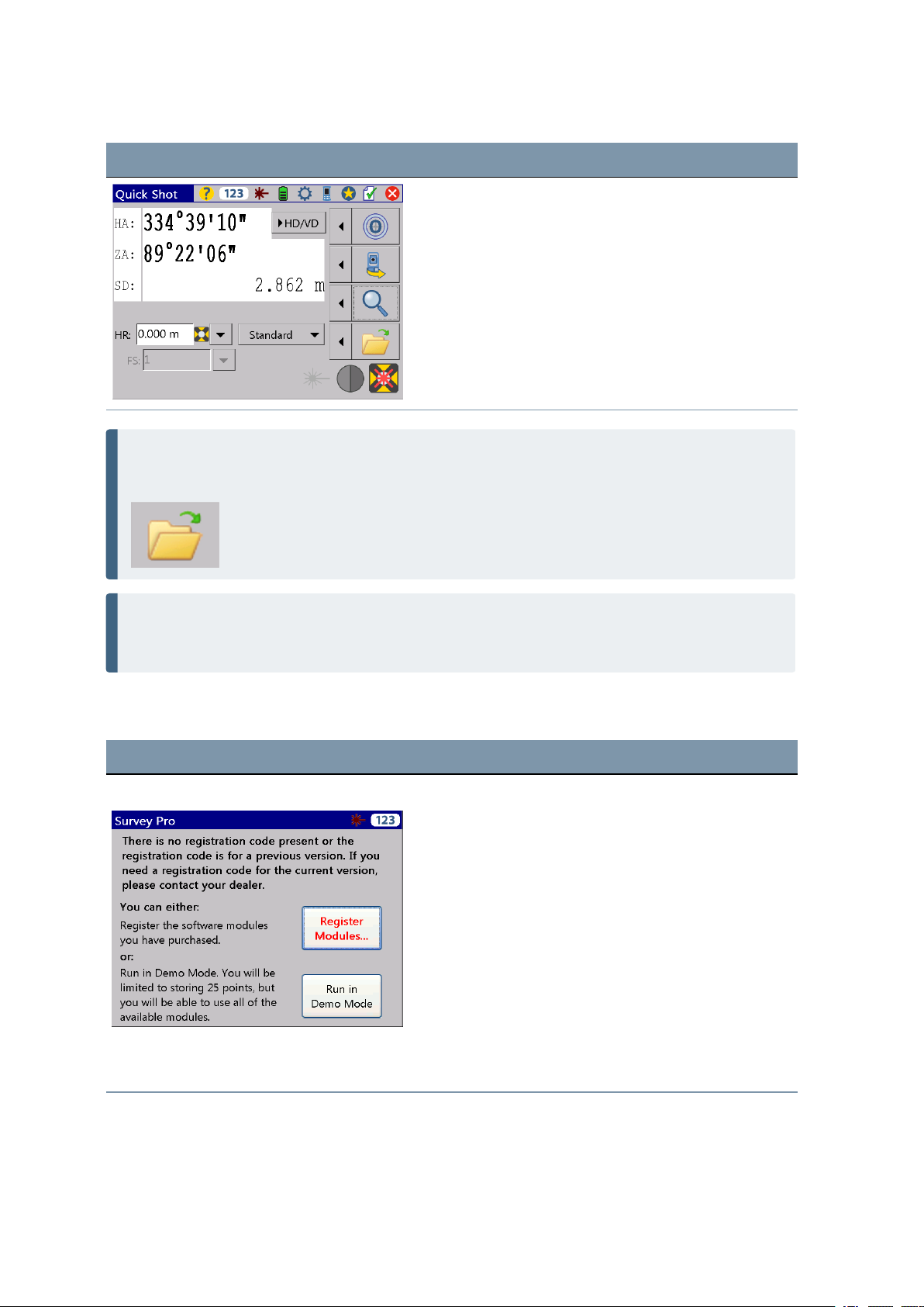
NOTE – Survey Pro cannot start without a job being open, so you have to open or create a new job
(file). In case you close the Quick Shot menu before you open or create a new job, Survey Pro will
be closed.
4 Setup
NOTE – If the laser pointer is in use it can be switched OFF in two different ways: 1. Switch OFF the
laser pointer and the instrument will still stay in reflectorless mode. 2. Change from reflectorless
mode into prism mode and the instrument will stay in prism mode.
Lookup and register the Survey Pro Software
Screen Actions and Comments
Registration Modules menu After the initial start of the Survey Pro software, the
following menu will appear. Please select Register
Modules and enter your registration code(s).
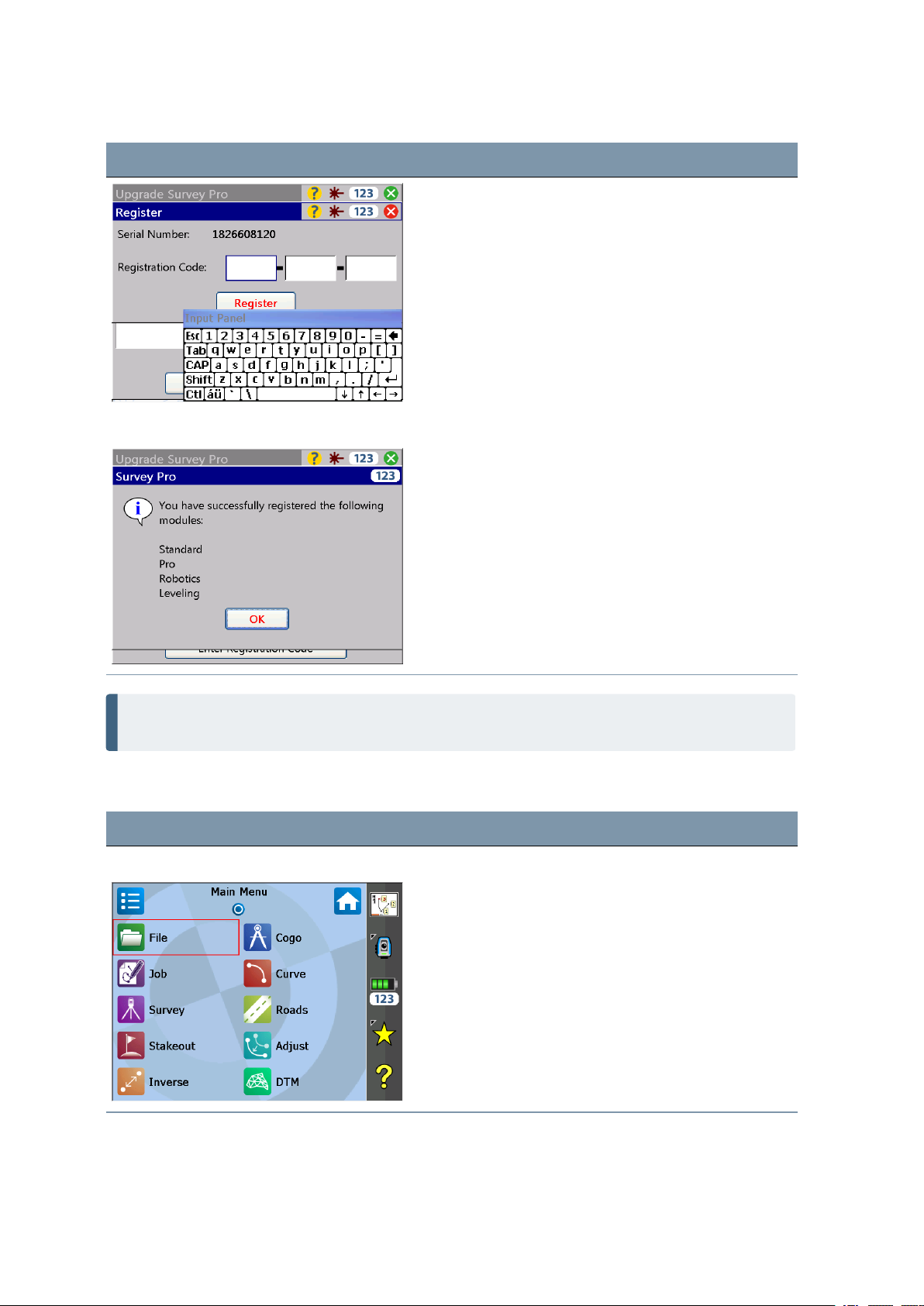
How to enter codes Please use the keyboard on the screen to enter
registration code.
FOCUS 35 TotalStation User Guide | 50
Page 51
Screen Actions and Comments
Finalizing registration codes
4 Setup
NOTE – If you select Run In Demo Mode, all areas of the software are available, with the limitation
a job cannot exceed 25 points.
Open or create a Job
Screen Actions and Comments
Survey Pro Main Menu Select the Filemenu.
FOCUS 35 TotalStation User Guide | 51
Page 52
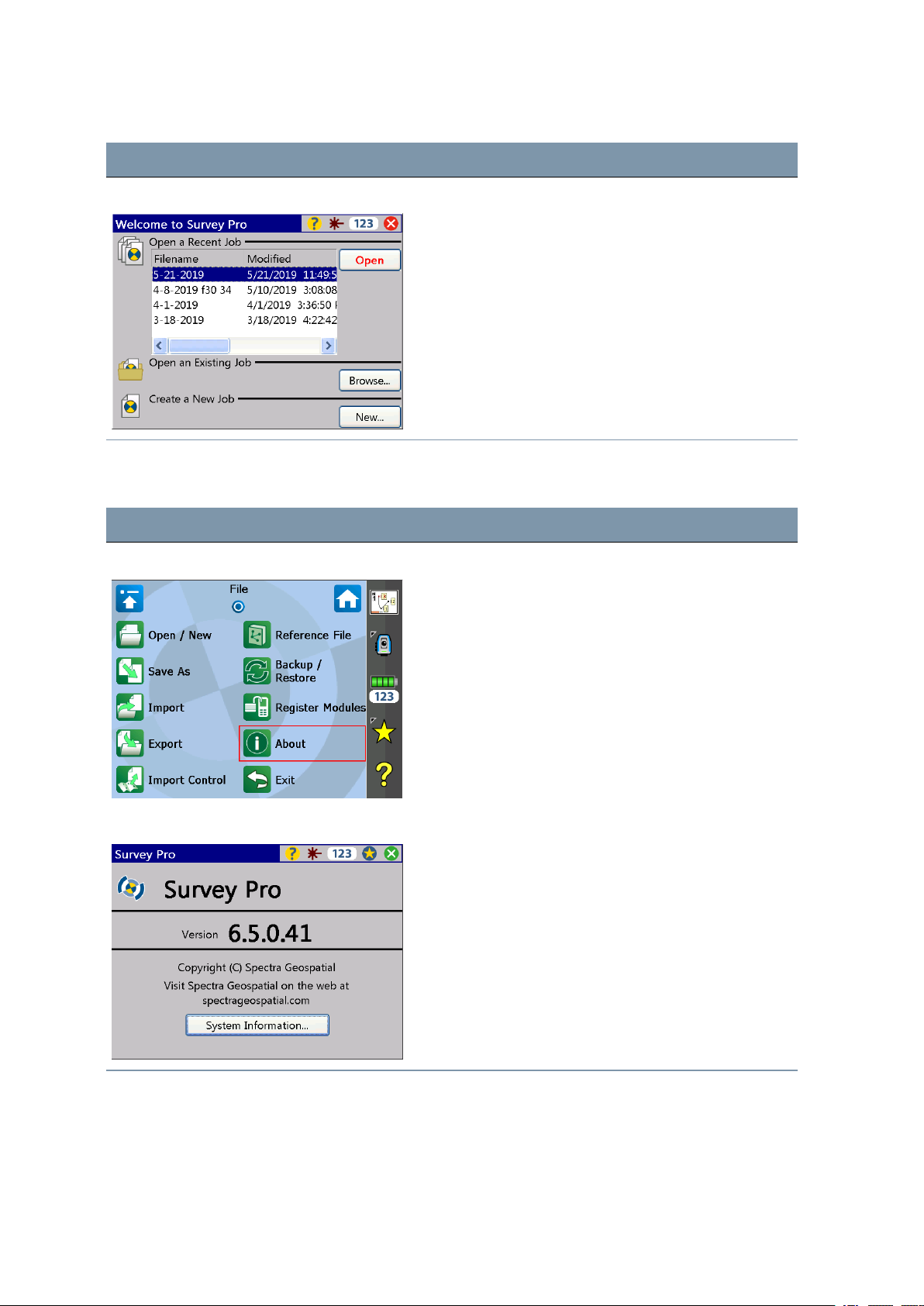
Screen Actions and Comments
Menu to work with jobs Select a file with Open or create a New Job with New.
Survey Pro Version Number
Screen Actions and Comments
4 Setup
Main Menu File About Select menu File and menu element About and the
software version appears on the screen.
Survey Pro Version Press the ESC button and the program will return
automatically to the Main Menu.
FOCUS 35 TotalStation User Guide | 52
Page 53
4 Setup
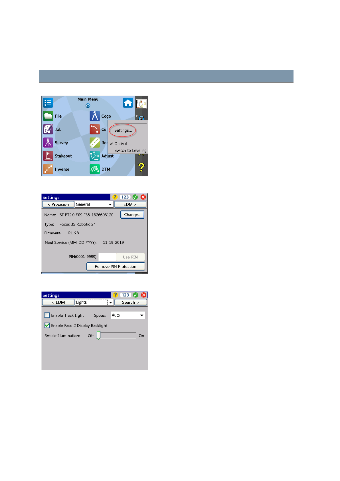
Settings Face2 Display Backlight, Reticle Illumination and Tracklight
Screen Actions and Comments
Main Menu Survey Pro Select instrument Settings by tapping on this icon.
Menu for Settings Navigate to Lights via drop down menu or toggle through
the submenus with D key left or right.
Menu for Lights Settings Make selections and confirm the settings.
FOCUS 35 TotalStation User Guide | 53
Page 54
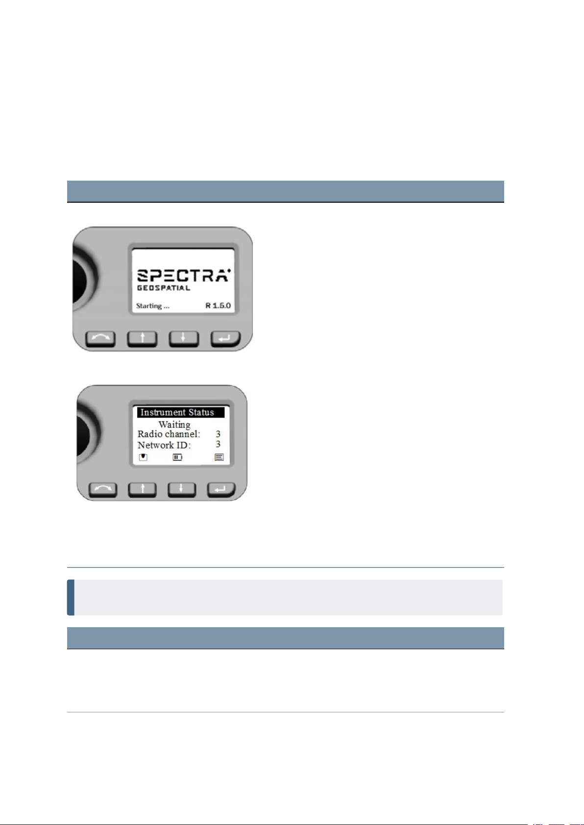
Starting and Settings via Face2 Control Unit
Start Screen
Before following any of the instructions below, put the instrument in the Face2 position. Start the
instrument by pressing the trigger key for one single beep.
Screen Actions and Comments
Start screen Face2 Control Unit After starting the screen will display the Spectra
Geospatial logo and the firmware version. The
instrument checks for an available connection on the set
Radio Channel and Network ID for several seconds and
then goes to Waiting state.
4 Setup
Instrument Status Menu - Waiting First function - Key description
U - Change Face
N - Scroll up
O - Scroll down
P - Enter
Second function - on screen symbols - short key press,
e.g.
N - Leveling menu
O - Status for battery and external power supply status
P - Instrument Settings
NOTE – StepDrive motor system and FOCUS System are usable while the Instrument Status menu
shows Waiting.
Screen Actions and Comments
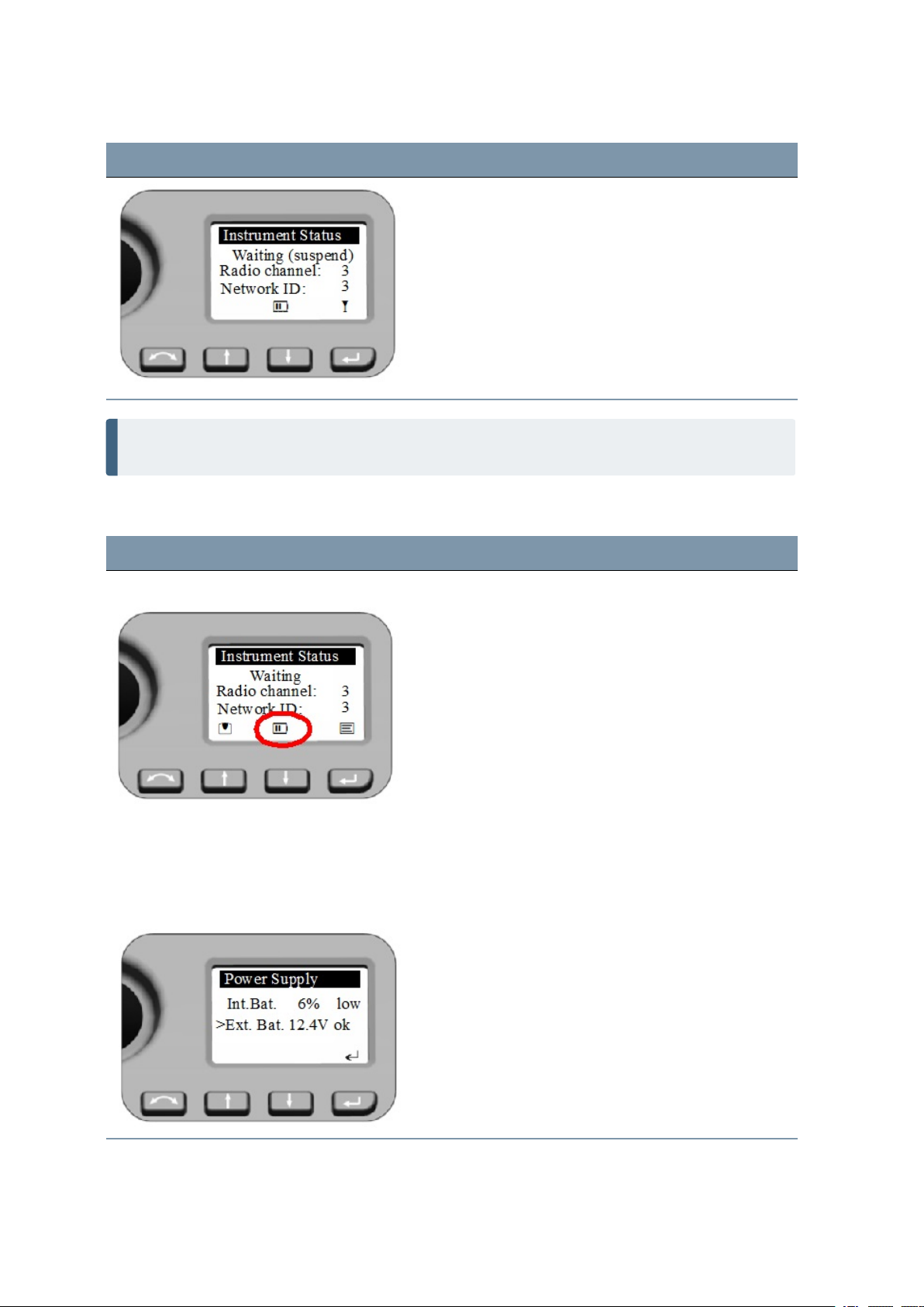
Instrument Status Menu - Suspend After Starting: If the instrument is inactive for longer
than 5 minutes it will go into Suspend Mode, see also
Suspend Mode and Power Management. The display will
show Waiting (suspend).
FOCUS 35 TotalStation User Guide | 54
Page 55
Screen Actions and Comments
The instrument will leave the Suspend Mode by starting
the field software at the instrument, a short P key
press or a z key press (single beep).
* - Indicates Suspend Mode
NOTE – In Suspend Mode - menu shows Waiting (suspend) - instrument and telescope can be
turned by hand, whereas StepDrive motor system and Focus System are not usable.
Status Power supply
4 Setup
Screen Actions and Comments
Instrument Status Menu - Waiting
Symbol for battery (&) or external power (F) supply.
Battery symbol with bars or x indicates battery capacity:
& - 75 to 100%
$ - 50 to 75%
? - 25 to 50%
! - less than 25% (below 10% ok will be changed to low)
( - no function possible
For more details and information about external power
supply select with a short O key press in the Power
Supply Menu.
Power Supply - external source Menu shows the voltage of the source.
Leave the menu with P press.
FOCUS 35 TotalStation User Guide | 55
Page 56
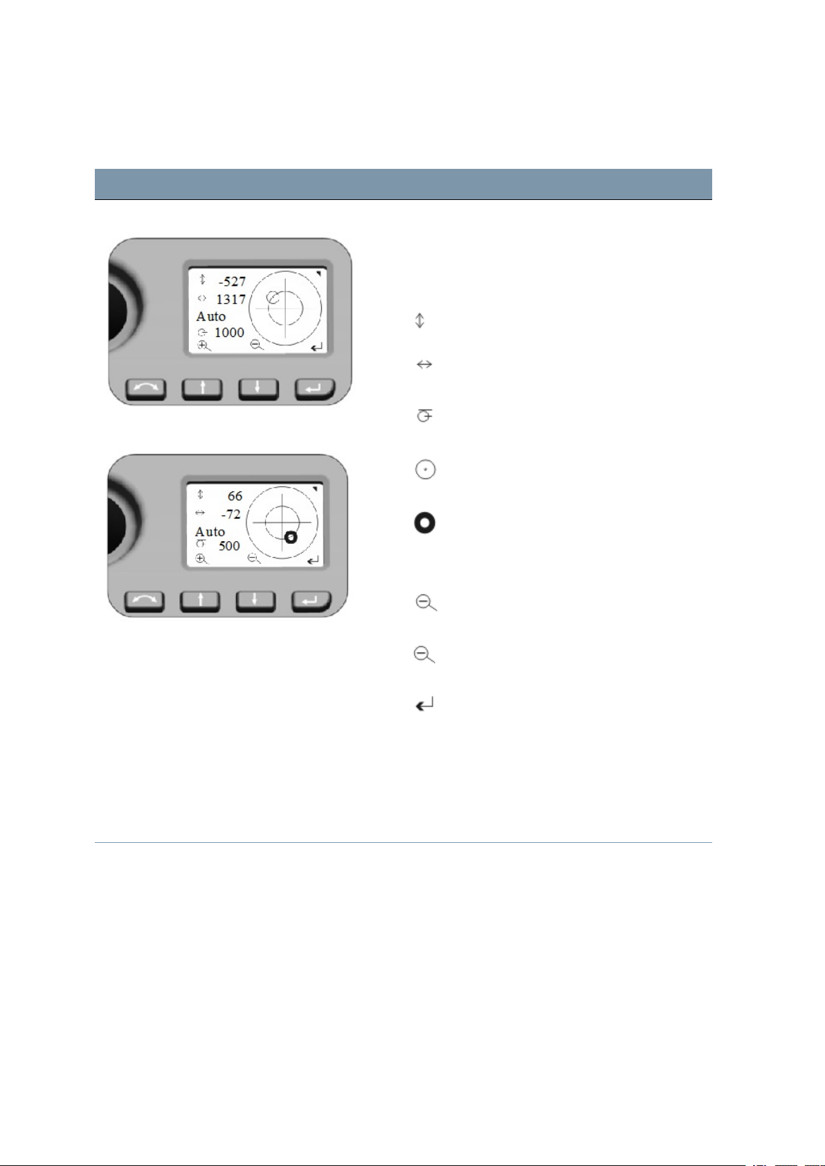
Leveling
Screen Actions and Comments
4 Setup
Leveling Menu
Leveling Menu bubble adjustment
Once you have selected the Level menu, the
electronic bubble appears in Face2 display.
NOTE – Values always in 0.1 mgon; (0.3 mgon = 1”;
0.1 mgon = 1 cc)
Telescope direction
Trunnion Axis direction
Bubble Scale value (Auto - max. 35 000;
min. 500)
Instrument inclination> 100 mgon
Instrument inclination < 100 mgon
Second key functions
Scale expansion (Manual mode - min. 100)
Scale reduction (Manual)
Back to Instrument Status menu
NOTE – If there is field software at Control Unit
Face1 started, this field software controls the
Face2 display. While using the field software in
every menu the Main Menu from the Face2 display
can be opened with a long P key press!
FOCUS 35 TotalStation User Guide | 56
Page 57

4 Setup
Security
To avoid unauthorized use of the instrument, you can activate a PIN / PUK security code.
PIN code
The PIN code is a four-digit code where each digit can be set to a number between 0–9, for example,
1234. If an incorrect PIN code is entered more than ten times, the instrument is locked and the PUK
code must be entered, see PUK code, page 58.
By default, the PIN code is set to 0000. With this code set, security is not activated and the user is not
prompted to enter the PIN code at start up.
The user can activate or change the PIN code (see following topic).
Activating or changing the PIN code
On the Face 2 display, press N or Oto scroll up or down until you see Set PIN and then press P.
Press N or O to enter the PIN of your choice digit by digit—press P to accept each digit.
After all digits have been set, press P to record the pin.
The menu returns to Set PIN.
Using the PIN code to unlock the instrument
When the PIN code has been activated, you must enter it when you start up the Instrument. To do this:
Switch on the FOCUS 35 instrument. The Face 2 display shows the menu Enter PIN.
Press N or Oto enter the PIN of your choice digit by digit—press P to accept each digit.
Once all valid digits have been entered, press P. This unlocks the instrument—the Face 2 display now
shows the menu Instrument Status, the Radio Channel, and the Network ID.
If an incorrect PIN code is entered more than ten times, the instrument is locked and the PUK code must
be entered, see PUK code. When the correct PUK code is entered, the PIN code is reset to 0000 and the
security PIN code is deactivated.
FOCUS 35 TotalStation User Guide | 57
Page 58
4 Setup
PUK code
The PUK (Personal Unlock Key) code is factory set on each instrument and cannot be changed by the
user.
If the PUK code has been lost, contact your authorized Spectra Geospatial distributor to retrieve it.
If an incorrect PIN code is entered more than ten times, the Error menu appears on the Face 2 display
with the error message Invalid PIN and Instrument Locked and shows the softkeys PIN and PUK.
Press PUK. The Enter PUK menu appears on the F2 display and shows PUK: 000000000000.
Press N or O to enter the PUK code digit by digit—press P to accept each digit.
Once all valid digits have been entered, press P. The FOCUS 35 instrument is unlocked, the PIN code is
reset to 0000 and the security PIN code is deactivated.
If an incorrect PUK code is entered (any number of times), Error menu appears on the Face 2 display with
the softkeys Cancel and Retry. Select Retry to enter the PUK code again or select Cancel to abort the
procedure.
Face2 Display while using the Survey Pro Software in
different Instrument Versions
StepDrive and LockNGo versions
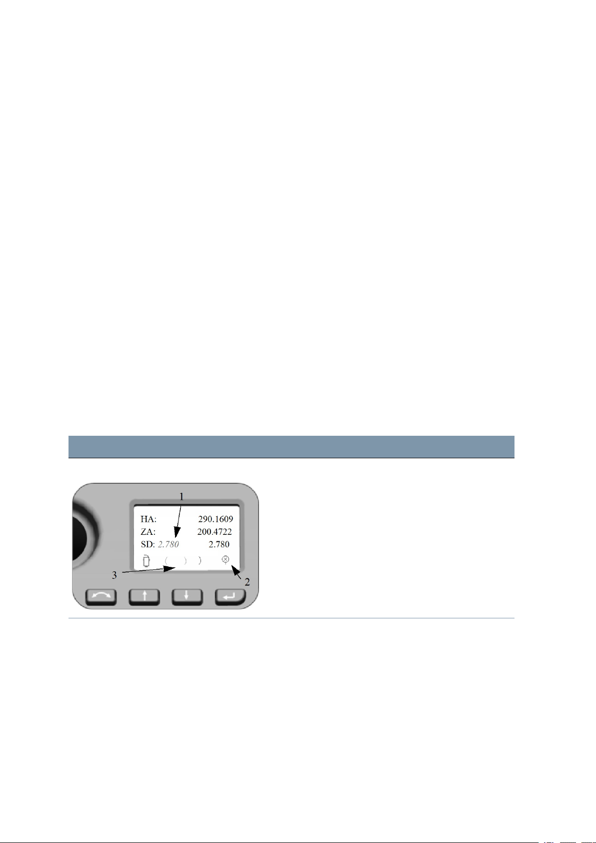
If the field software at Control Unit Face1 is started, the field software controls the Face2 display.
Screen Actions and Comments
F2 Display while program Survey Pro The Face2 display always shows measurement results
parallel to the Face1 Control Unit.
1. SD value from the last measurement jumps to left.
2. Symbol Prism or Reflectorless target
3. Symbol moves and shows the measurement
progress. Different symbols for status LockNGo.
NOTE – While using the field software in every menu the
Main Menu from the Face2 display can be opened with a
long P key press!
FOCUS 35 TotalStation User Guide | 58
Page 59
4 Setup
Robotic and RX versions
If you are using an external controller (independent with radio or cable) with field software that has been
started, the controller with field software controls Face2 display.
Screen Actions and Comments
F2 Display while Robotic mode The Face2 Display in this configuration shows no
measurement results.
NOTE – While using the field software at the external
Control Unit the Level Menu or Main Menu from the Face2
display can be opened.
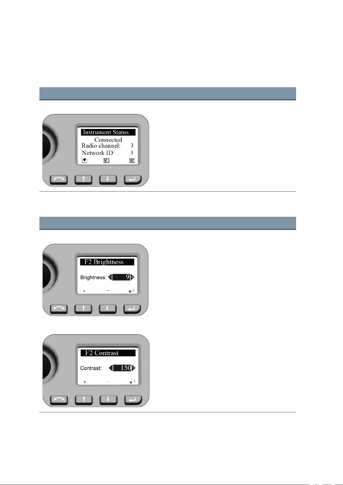
Brightness and Contrast
Screen Actions and Comments
Brightness Menu
Contrast Menu
Select with a long press of N key the setting menu for
Brightness.
Adjust the Brightness by pressing N or O.
Confirm the selection with P.
Brightness range: 0 - 20
Select with a long press of N key the setting menu for
Contrast.
Adjust the contrast by pressing N or O.
Confirm the selection with P.
Contrast range: 0 - 256
FOCUS 35 TotalStation User Guide | 59
Page 60
NOTE – Setting function for brightness and contrast is available on every F2 menu.
Main Menu Face2 - Information and Settings
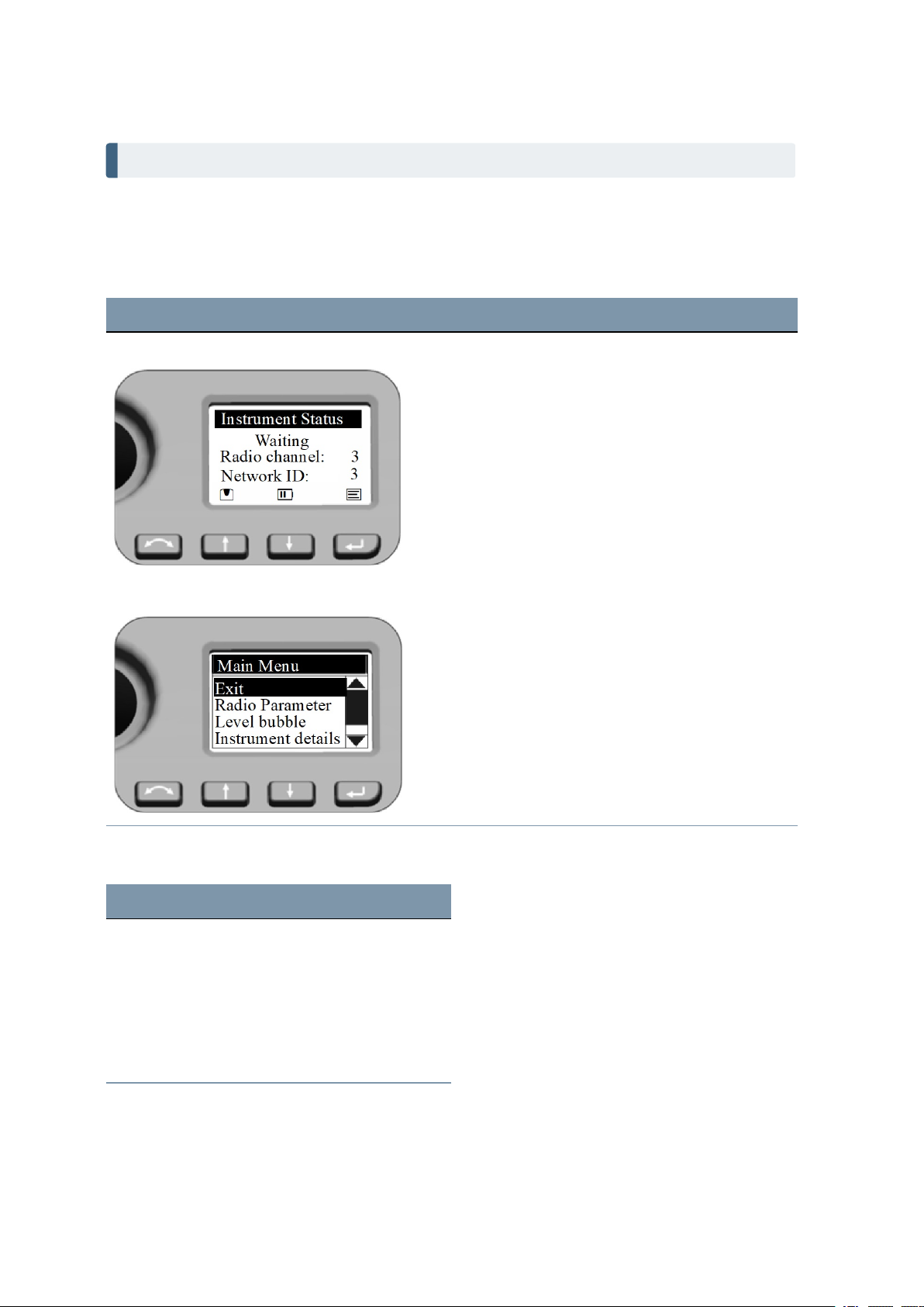
With the Face2 display, you can access a number of functions and routines without starting the field
software at Control Unit Face1.
Screen Actions and Comments
4 Setup
Instrument Status Menu
Main Menu
Select Main Menu by pressing P.
Navigate with the N or O key in the Main Menu to
highlight the item you want to select.
Confirm a selection by pressing the P key.
The Main Menu is structured as follows:
Content See ...
Exit
Radio Parameter page 61
Level bubble page 61
Instrument details page 61
Service menu page 62
FOCUS 35 TotalStation User Guide | 60
Page 61
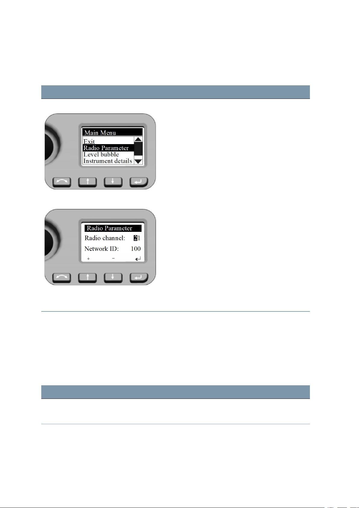
Radio Parameter
In the Radio Parameter menu it is possible to set the radio channel and network ID number.
Screen Actions and Comments
4 Setup
Main Menu To set
Radio Parameter When entering this menu the cursor jumps to the first
Radio Channel
to scroll to
digit of the Radio channel, first digit is active (inverse)
and with N or O the numbers 0-9 can be selected.
Press P when number is correct - cursor jumps to the
next digit.
After you have selected the last digit for the Radio
channel the cursor jumps to the settings for Network ID
with the same procedure.
When last digit of Network ID is confirmed, the system
jumps back to the Main Menu.
Radio Parameter
and
Network ID
, pressNand
and pressP.
O
Radio channel range: 1 - 30
Network ID range: 0 - 255
Level Bubble
These details are already described in Leveling, page 56.
Instrument Details
The Instrument Details menu displays the Instrument Version, Instrument name (your definition),
Serial number and Firmware version.
Screen Actions and Comments
Main Menu
To read Instrument Details, press N or O to scroll to
Instrument Details and press P.
FOCUS 35 TotalStation User Guide | 61
Page 62
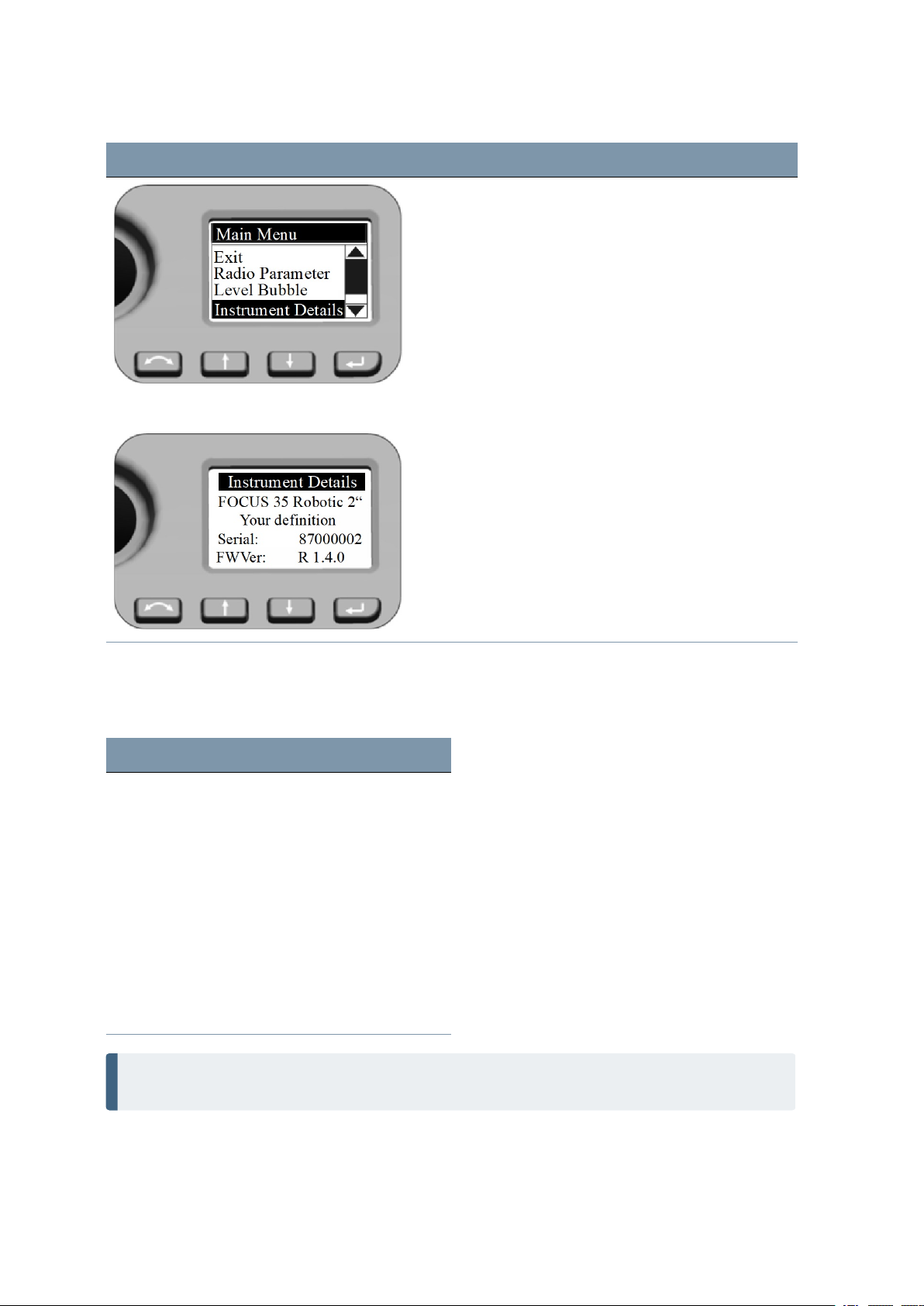
Screen Actions and Comments
4 Setup
Instrument Details
Service menu
The Service Menu is structured as follows
Setting See ...
Exit
USB Interface setting page 63
System diagnose page 63
Leave the menu by pressing the P key.
External EDM Frequency page 64
External EDM calibration settings page 65
Drive Mode page 66
Radio configuration page 67
Next Service Date page 67
NOTE – The Service Menu is hidden—please contact your Spectra Geospatial Reseller for
instructions on how to access this option.
FOCUS 35 TotalStation User Guide | 62
Page 63
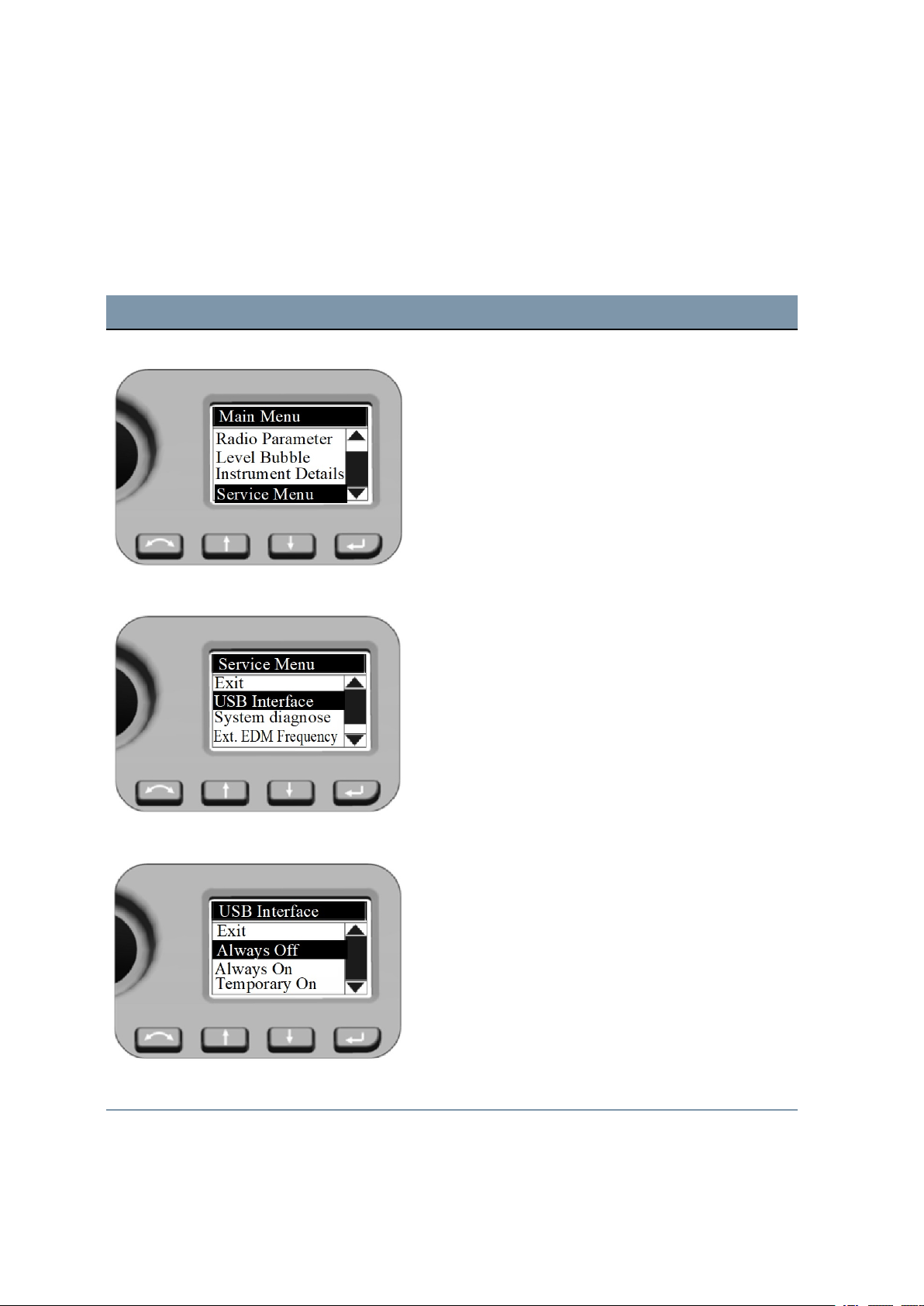
The Service Menu enables the following:
l USB interface settings
l Display and input of External EDM Calibration (scale and offset) for supplementary correction of
distance measuring units.
l Radio configuration (France only).
Screen Actions and Comments
4 Setup
Main Menu - Service Menu To select
Service Menu
Service Menu - USB Interface Settings To select
USB Interface
Service Menu
and pressP.
USB Interface
and pressP.
, pressNorOto scroll to
, pressNandOto scroll to
USB Interface Please make sure that the default setting USB Interface
for Customer is Always Off.
If the FOCUS 35 total station needs a firmware upgrade,
the USB interface setting must be set to Always On to
complete the firmware upgrade.
Service Menu - System diagnose PressNandOto scroll to
System diagnose
FOCUS 35 TotalStation User Guide | 63
and then
Page 64
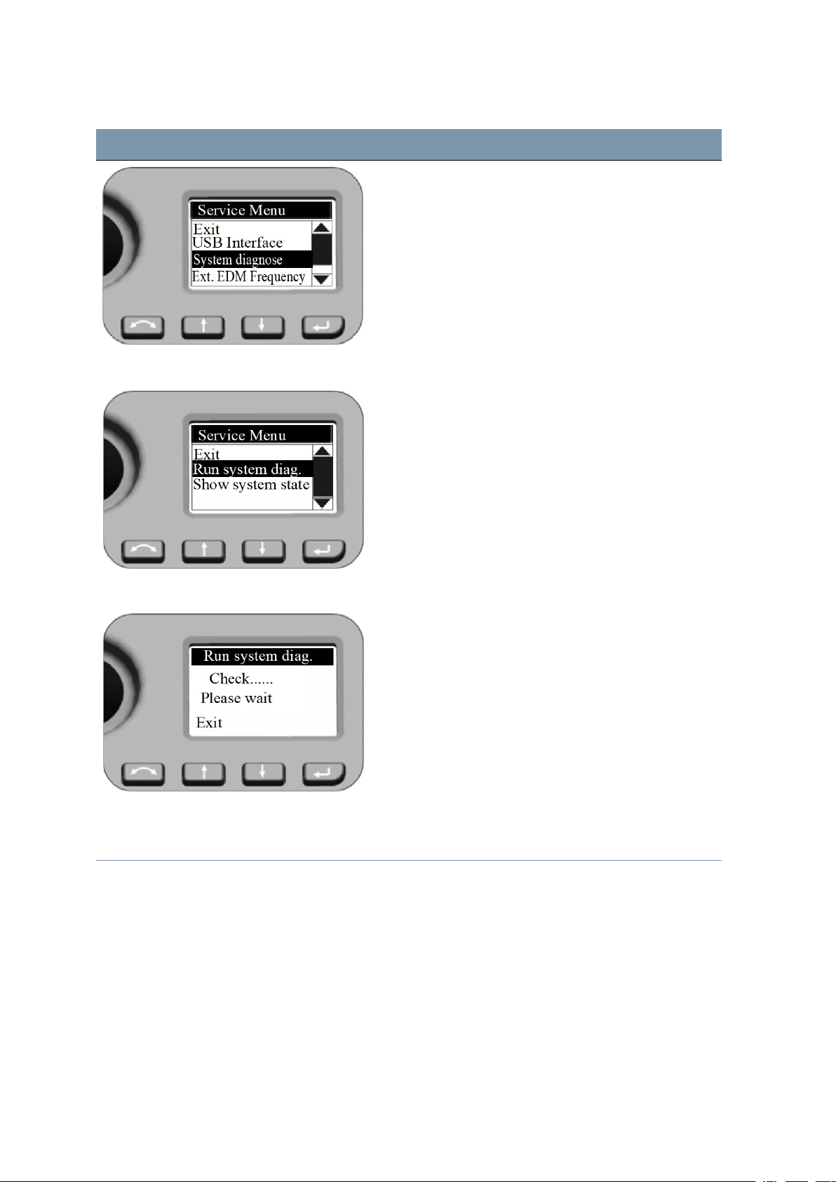
Screen Actions and Comments
pressP.
4 Setup
Service Menu - Run system diag.
Press N and O to scroll to Run system diag. and then
press P.
Show system state shows straightaway the most
recently obtained diagnose results.
System diagnose The diagnose program checks all instrument functions.
During the diagnosis process, you may be prompted to
turn the instrument knobs and be requested to aim to a
prism. At the end the program shows the results and
offers the possibility to store it.
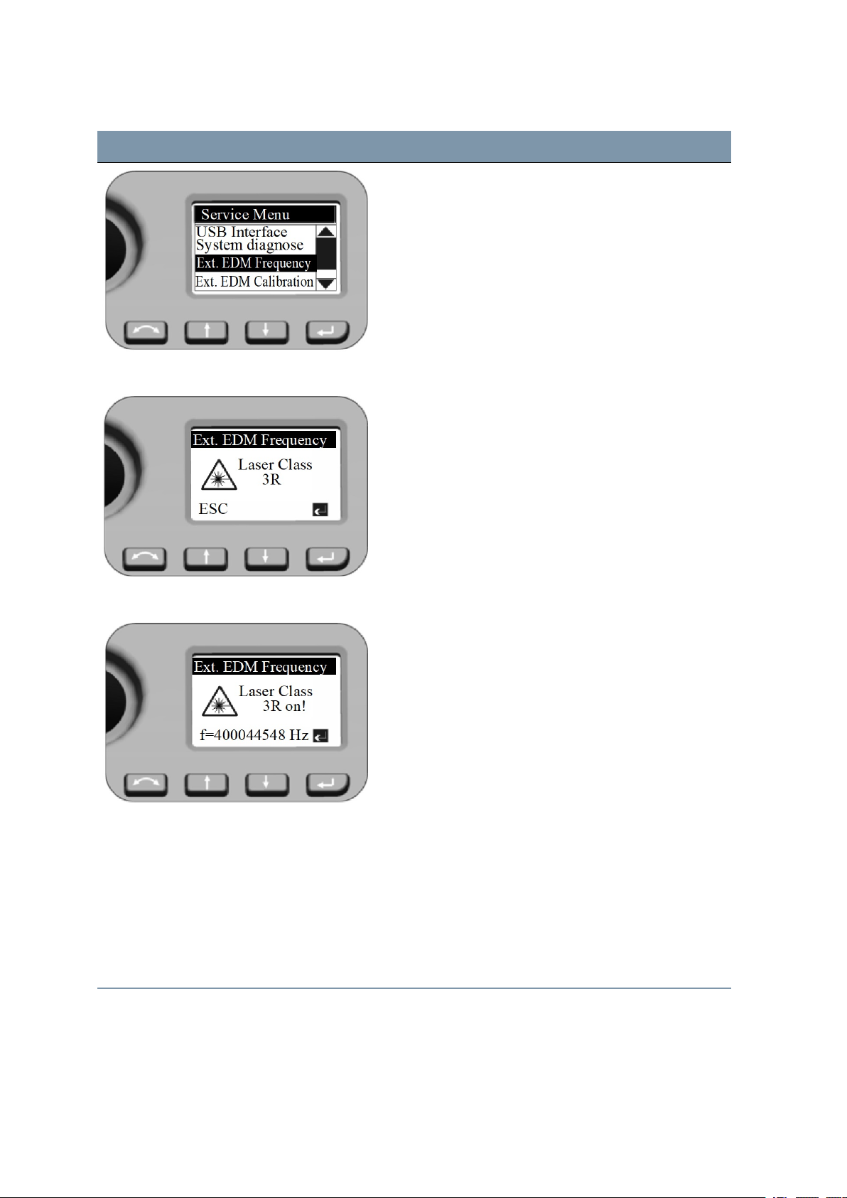
Service Menu - External EDM Frequency PressNandOto scroll to
then pressP.
Ext. EDM Frequency
FOCUS 35 TotalStation User Guide | 64
and
Page 65
Screen Actions and Comments
4 Setup
EDM Frequency
Press P to switch on the EDM Laser source with
modulated scale frequency.
Press N (ESC) to leave the menu.
EDM Frequency The unit in frequency calibration mode produces visible
Laser light emerging at the center of the telescope
objective. The Laser light conforms to Class 3R. Make
sure to do the external EDM frequency calibration
appropriate to all warnings and precautions at Laser
Safety (see page 4).
Nominal frequency will be displayed.
Press P to leave the menu.
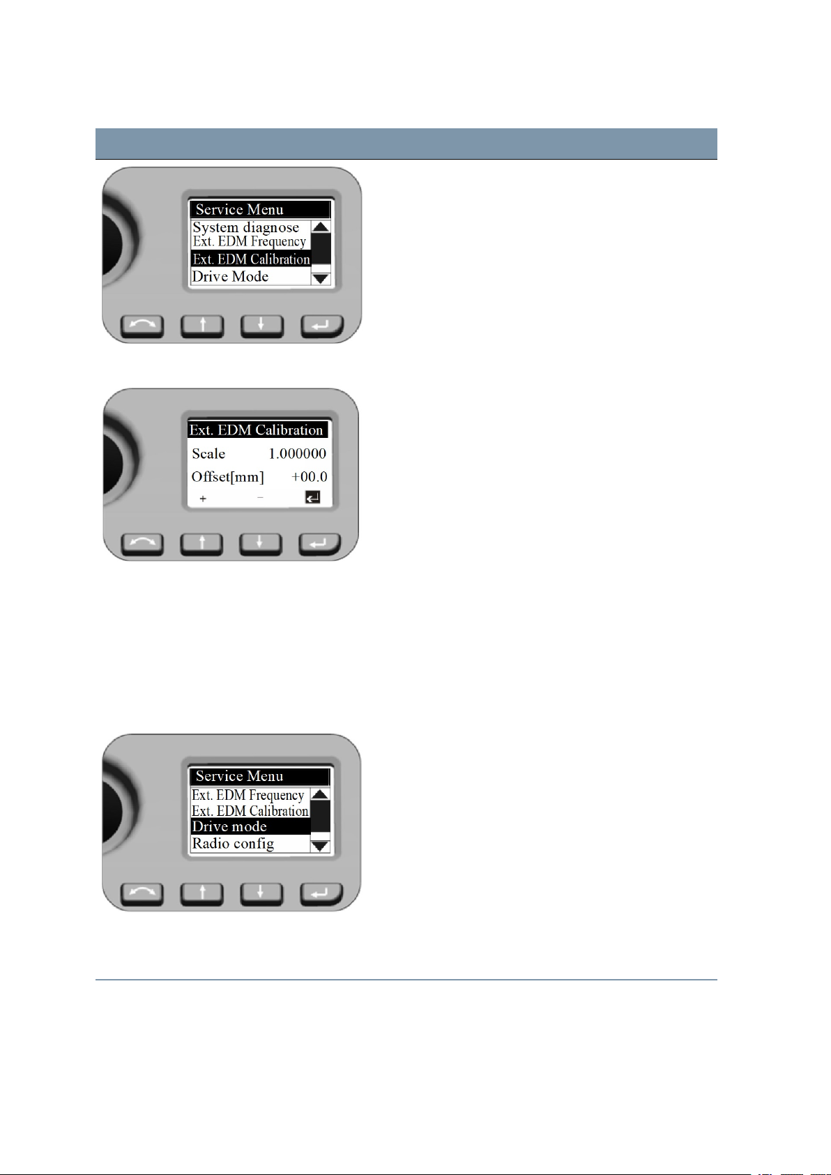
Service Menu - Ext. EDM Calibration Settings after external EDM calibration:
Press N or O to scroll to Ext.EDM Calibration and
press P.
Both values for External EDM Calibration influence the
measured distance directly! Therefore, they must have
been determined by means of an accurate external
calibration.
FOCUS 35 TotalStation User Guide | 65
Page 66
4 Setup
Screen Actions and Comments
External EDM Calibration When entering this menu the cursor stays always at the
P key. Press P when number is correct - the system
jumps back to the Service Menu.
To enter another value press N or O and the first digit
of the Scale is active (inverse) and with N and O the
numbers 0-9 can be selected. Press P when number is
correct - cursor jumps to the next digit.
After you have selected the last digit for the Scale press
P. The cursor jumps to the settings for Offset with the
same procedure.
When last digit of Offset is confirmed, the system jumps
back with the cursor to the inverse Psymbol.
Press Pkey a further time - the system jumps to
Service Menu.
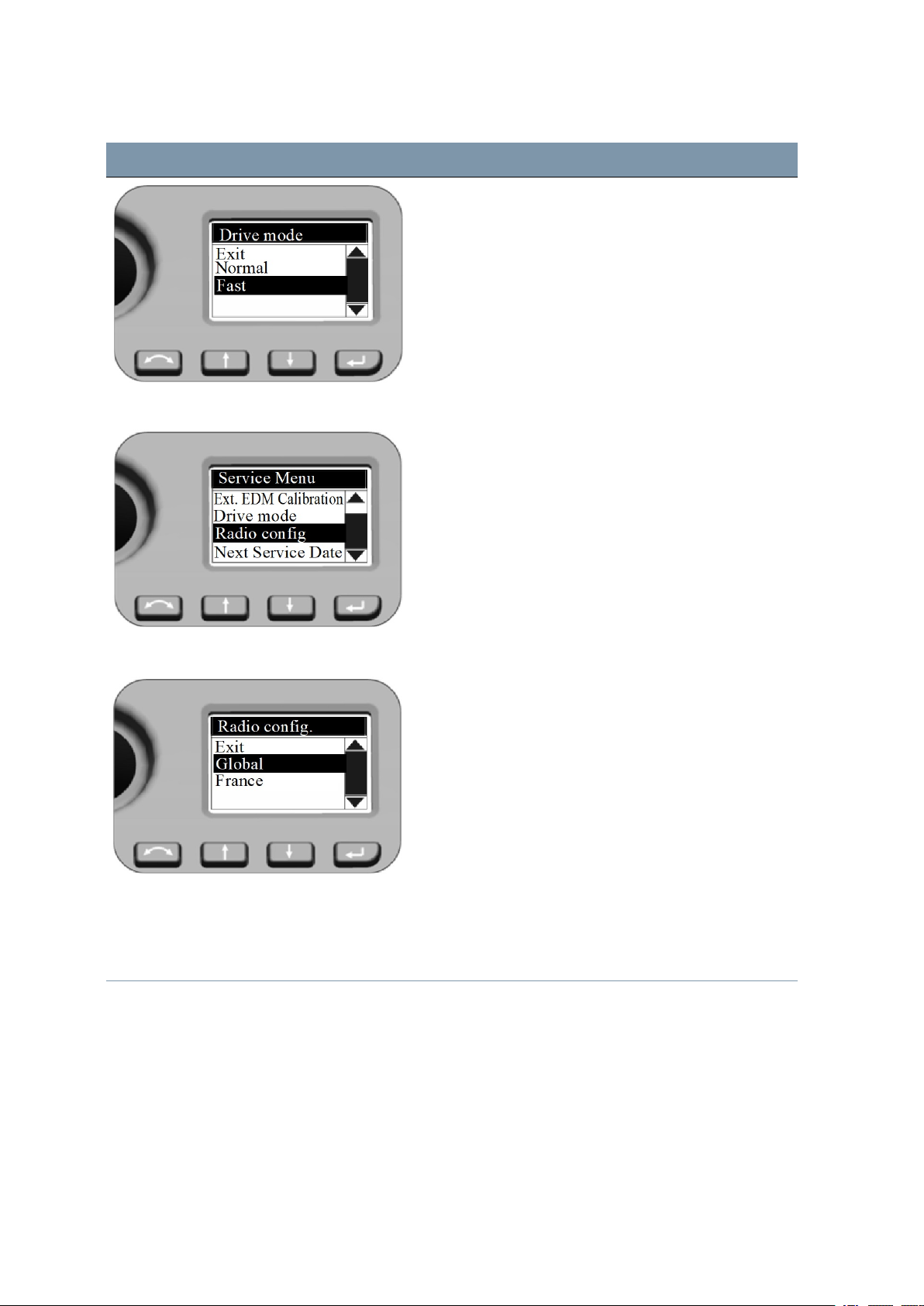
Service Menu - Drive Mode Settings for Drive Mode
Drive Mode settings have an effect while using LockNGo
Tracker technology for robotic surveying or while
changing face.
Press N and O to scroll to Drive Mode and then press
P.
Drive Mode
Press N and O to select Normal or Fast and then
press P.
FOCUS 35 TotalStation User Guide | 66
Page 67
Screen Actions and Comments
Normal:
This mode is the default mode. Mode is suitable for all
instrument mounts.
Fast:
Mode can be a choice for instrument mount on tripods.
Service Menu - Radio configuration Setting Radio configuration
Press N and O to scroll to Radio config. and then
press P.
4 Setup
Radio configuration Information to users in France only! To comply with
French radio regulations, the radio must be set to French
settings.
Press N and O to scroll to France and then press P.
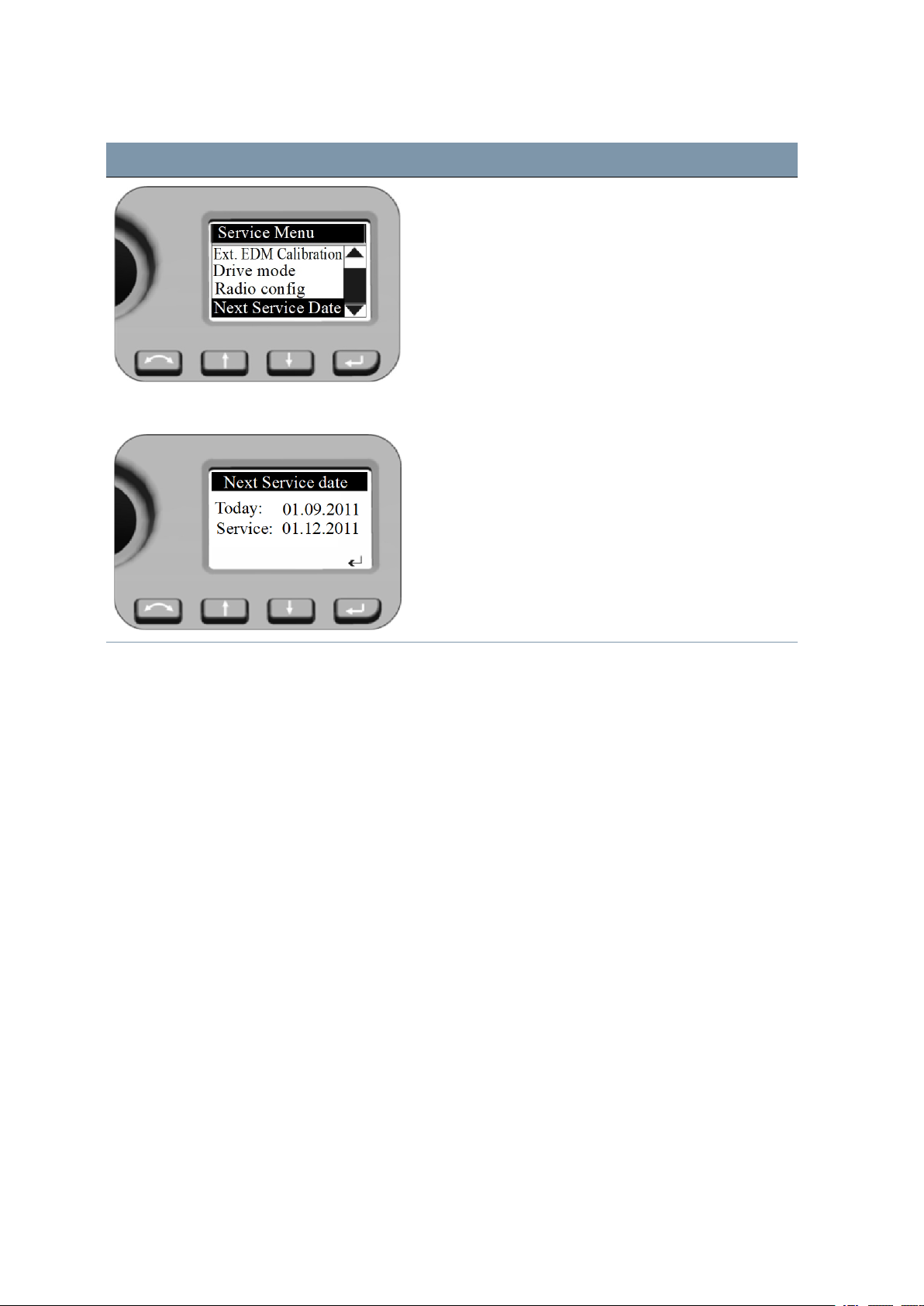
Service Menu - Next Service Date Setting Next Service date
Press N and O to scroll to Next Service date and
then press P.
FOCUS 35 TotalStation User Guide | 67
Page 68
Screen Actions and Comments
4 Setup
Next Service date
Press P to leave the menu.
If the Service date is already expired the program offers
the possibility to postpone the Next Service date (today
plus three months). This change will be logged internally.
Instrument Adjustment and Calibration
The section describes the instrument adjustments and calibration routines, adjustments for Laser
Pointer (see The Laser Pointer, page 72), for Optical Plummet (see Optical Plummet, page 77), and for
Tribrach Circular Level (see Tribrach Circular Level, page 79).
These adjustments and calibrations will change over time, the most common changes being caused by:
l Wear and tear with use
l Bumps and knocks during transit
l Large changes in operating temperature
Spectra Geospatial recommends that a collimation and calibration check be carried out routinely as
follows:
l After any long uncontrolled transport of the instrument (e.g., after service or shipment to a new
location)
l After any accidental knock or drop
l At any time when the operating temperature changes by more than 10 °C (18 °F)
l At any time when the instrument changes it's height above sea level by more than 500 m (1640 ft)
FOCUS 35 TotalStation User Guide | 68
Page 69

4 Setup
l At any time when the highest accuracy positions are required
l Routinely on a periodic basis (Monthly, weekly etc.)
Spectra Geospatial also recommends that the operator keep a record of the dates and values measured
so that any gross changes can easily be detected. Gross changes can indicate the need for a check by
an approved service center.
In all calibrations, multiple sightings will be made in both faces to ensure that any minor pointing errors
can be eliminated in the accurate determination of current collimation error values. All measured
collimation and calibration values are stored and used until a new set of values are determined.
In a new instrument the values should be close to zero, over time these will change.
Compensator
Before starting the routine, level the instrument. An internal instrument battery must be present in the
side battery compartment. For instruments with Face 1 battery option, this battery compartment must
be empty. The instrument will automatically check if the compensator is within range before the
calibration is started.
The calibration process involves the instrument automatically reading the compensator value at a series
of predetermined positionsthrough the full rotation of the instrument. The process takes approximately
one minute to complete. During the process the instrument should be on a stable platform, free from
vibration and untouched by the user.
Optical (HA/VA) Collimation and Trunnion Axis Tilt
The FOCUS 35 Total Station instrument utilizes precise angle and distance measurements to determine
the position of the point being measured. The instrument’s design facilitates the ability to measure all
points with a single pointing to the target in the Face1 position. All electronic total stations are subject to
collimation errors in both the horizontal and vertical angle measuring systems, and also errors caused by
the axis of the telescope not being truly perpendicular to the vertical of the instrument.
In order to compensate for these errors, the collimation routine allows the operator to accurately
determine the current errors in the instrument, and store the errors as corrections to be applied to all
measurements made in a single pointing to a target. In this way the FOCUS 35 Total Station will always
provide accurate measurements.
The adjustment of the instrument for HA/VA collimation and Trunnion Axis tilt is a two stage process.
LockNGo Tracker
Only on Instruments with LockNGo capability:
The LockNGo Tracker unit is designed to be coaxial with the instrument cross hairs. If for any reason the
alignment of the tracker deviates from the line of the telescope cross hairs, then errors in position of
the point being measured would result. For this reason an LockNGo collimation check needs to be
carried out on a regular basis to ensure that any slight misalignment is corrected for. Perform the test
over a similar distance as that you will be working on, but at least 100 m (328 ft).
FOCUS 35 TotalStation User Guide | 69
Page 70
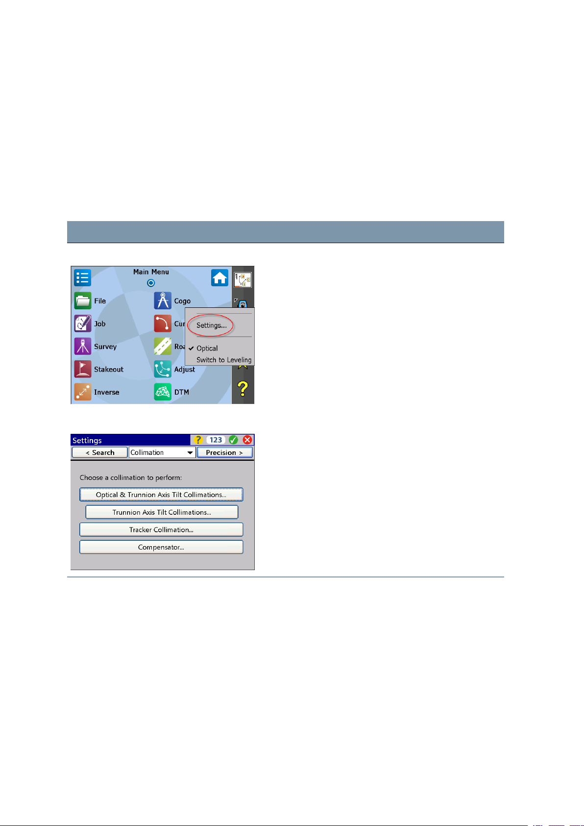
4 Setup
The prism target must be very still during the test (Spectra Geospatial recommends that you use a tripod
or bipod mount for the target) and must be in clear line of sight without any obstructing traffic. The
instrument is calibrated to accurately point at the center of the target in both horizontal and vertical
axes. The calibration is used to correct the positions of all points measured using the LockNGo Tracker
function.
Adjustment Routines in Survey Pro software (if available)
Start the Survey Pro software. During the process the instrument should be on a stable platform.
Screen Actions and Comments
Main Menu Survey Pro Select instrument Settings by tapping on this icon.
Settings Collimation Navigate to Collimation via drop down menu or toggle
through the submenus withDkey left or right. Select
the appropriate adjustment.
FOCUS 35 TotalStation User Guide | 70
Page 71
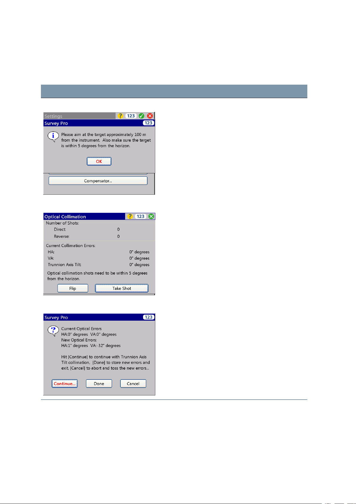
Optical Collimation
The workflow is structured as follows:
Screen Actions and Comments
Collimation conditions Make sure to measure with the stated conditions.
Optical Collimation measurements Make the measurements per the displayed information
and confirm and store the values.
4 Setup
Optical Collimation / Trunnion Axis Decide per the displayed information for trunnion axis tilt
collimation or confirm and store the new values for
optical collimation.
FOCUS 35 TotalStation User Guide | 71
Page 72
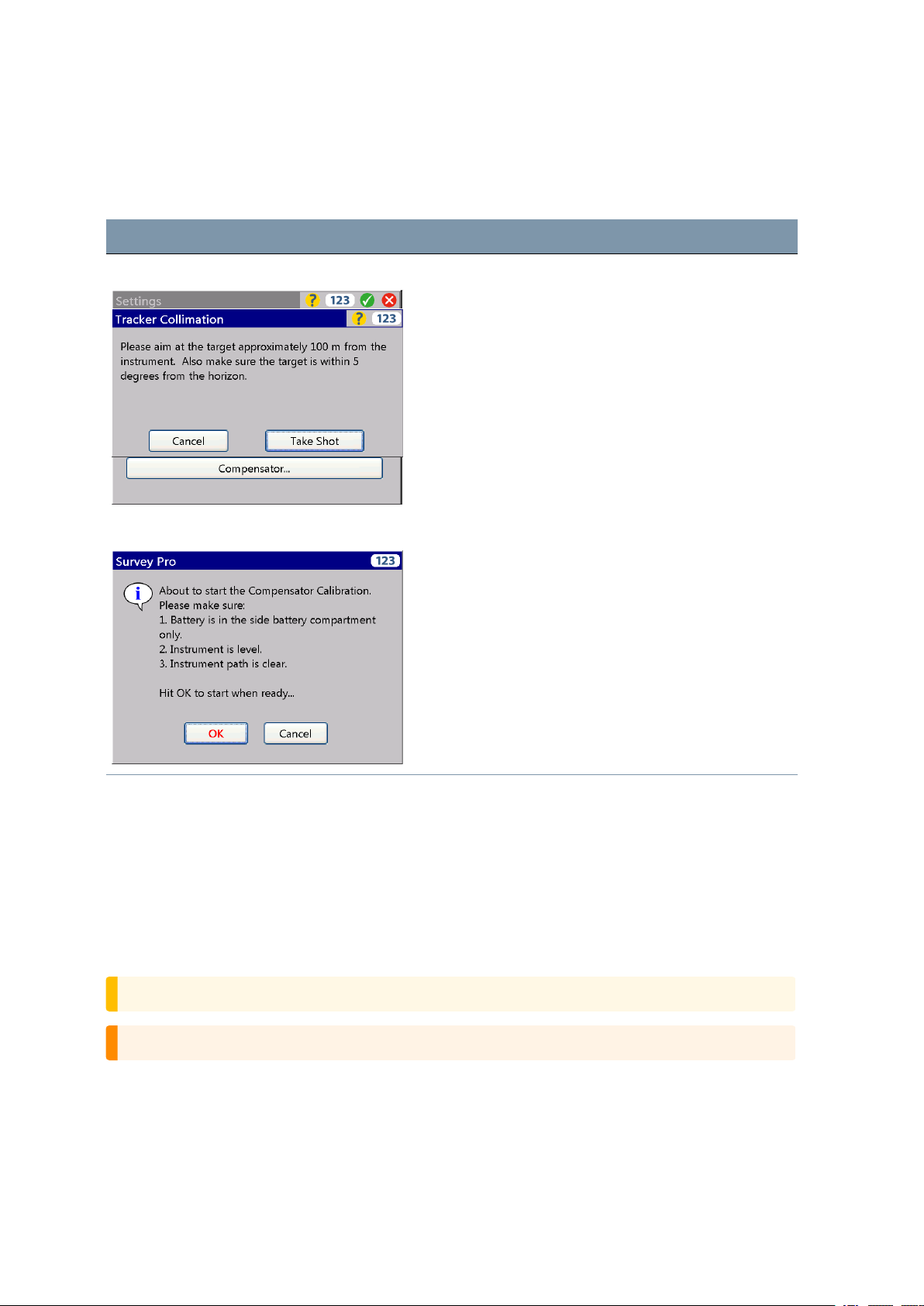
Tracker Collimation and Compensator Collimation
Start screens are:
Screen Actions and Comments
Tracker Collimation start screen Make sure to measure with the stated conditions.
Compensator Collimation start screen Make the measurements per the displayed information.
During the process the instrument should be free from
vibration and untouched by the user.
4 Setup
The Laser Pointer
The FOCUS 35 Total Station uses a red laser beam to measure and as a Laser Pointer. The Laser Pointer
is coaxial with the line of sight of the telescope. If the instrument is well adjusted, the red Laser Pointer
coincides with the line of sight. External influences such as shock or large temperature fluctuations can
displace the red Laser Pointer relative to the line of sight.
Aligning the Laser Pointer
CAUTION – Viewing the laser spot on the adjustment target through the telescope is safe.
WARNING – Do not try to make the adjustment using a prism, see Laser Safety, page 4.
FOCUS 35 TotalStation User Guide | 72
Page 73
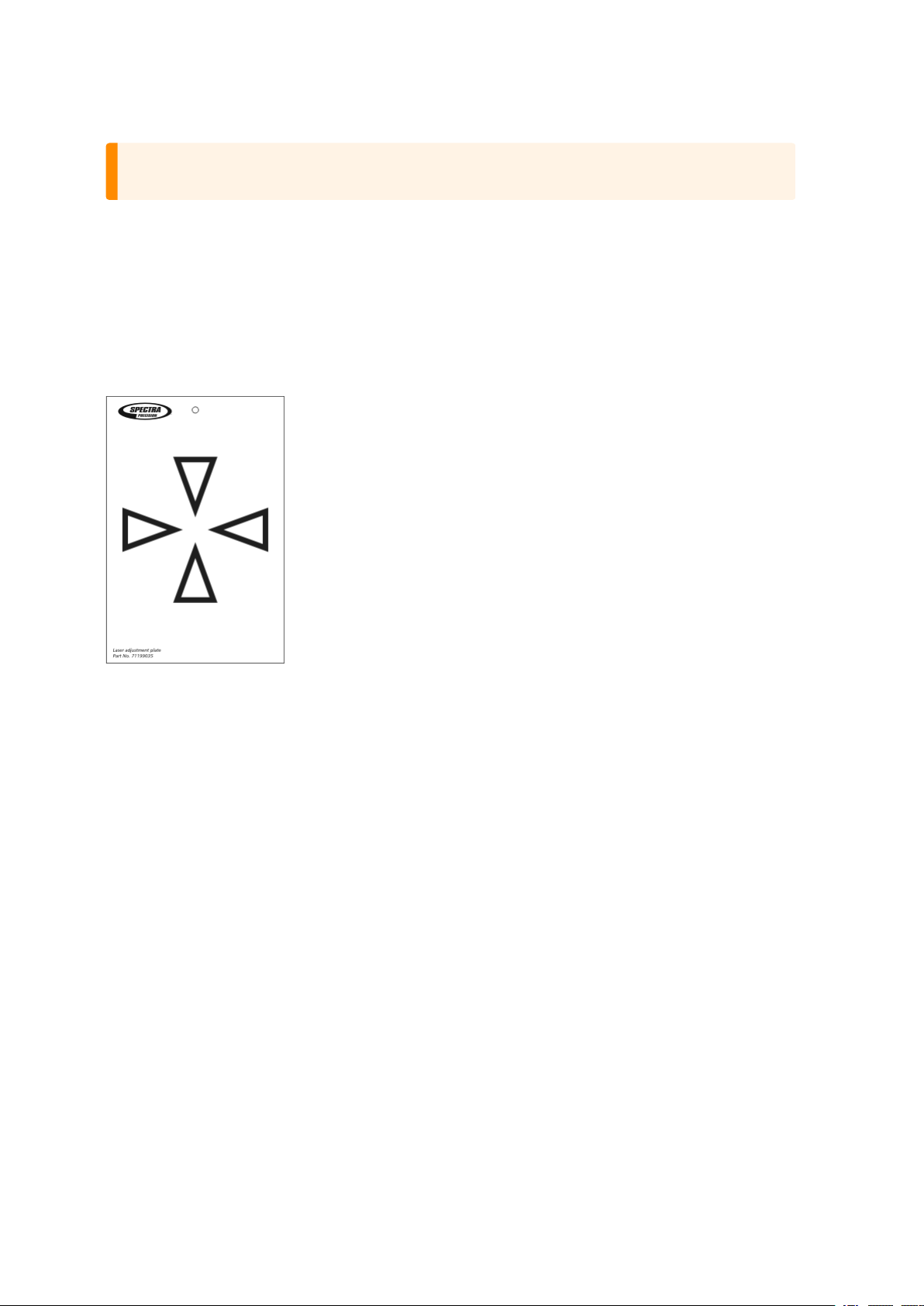
4 Setup
WARNING – Do not use the Laser Pointer as an aid when searching for prisms, see Laser Safety,
page 4.
To avoid faulty measurements using the Laser Pointer, use the supplied adjustment target to check the
laser alignment regularly and before you attempt precise distance measurements:
Setup the adjustment target 10-15 meters (30-50 ft) away, facing the instrument.
Aim the instrument to the center of the target plate and then inspect the position of the red laser spot in
relation to the telescope cross-hairs.
If the red laser spot lies outside the cross-hairs, adjust the direction of the beam until it matches the
cross-hairs, see the Laser adjustment plate, below:
Adjusting the Laser Beam
Pull out the two plugs from the adjustment ports of the telescope housing:
The image shows the Laser beam adjustment ports.
FOCUS 35 TotalStation User Guide | 73
Page 74
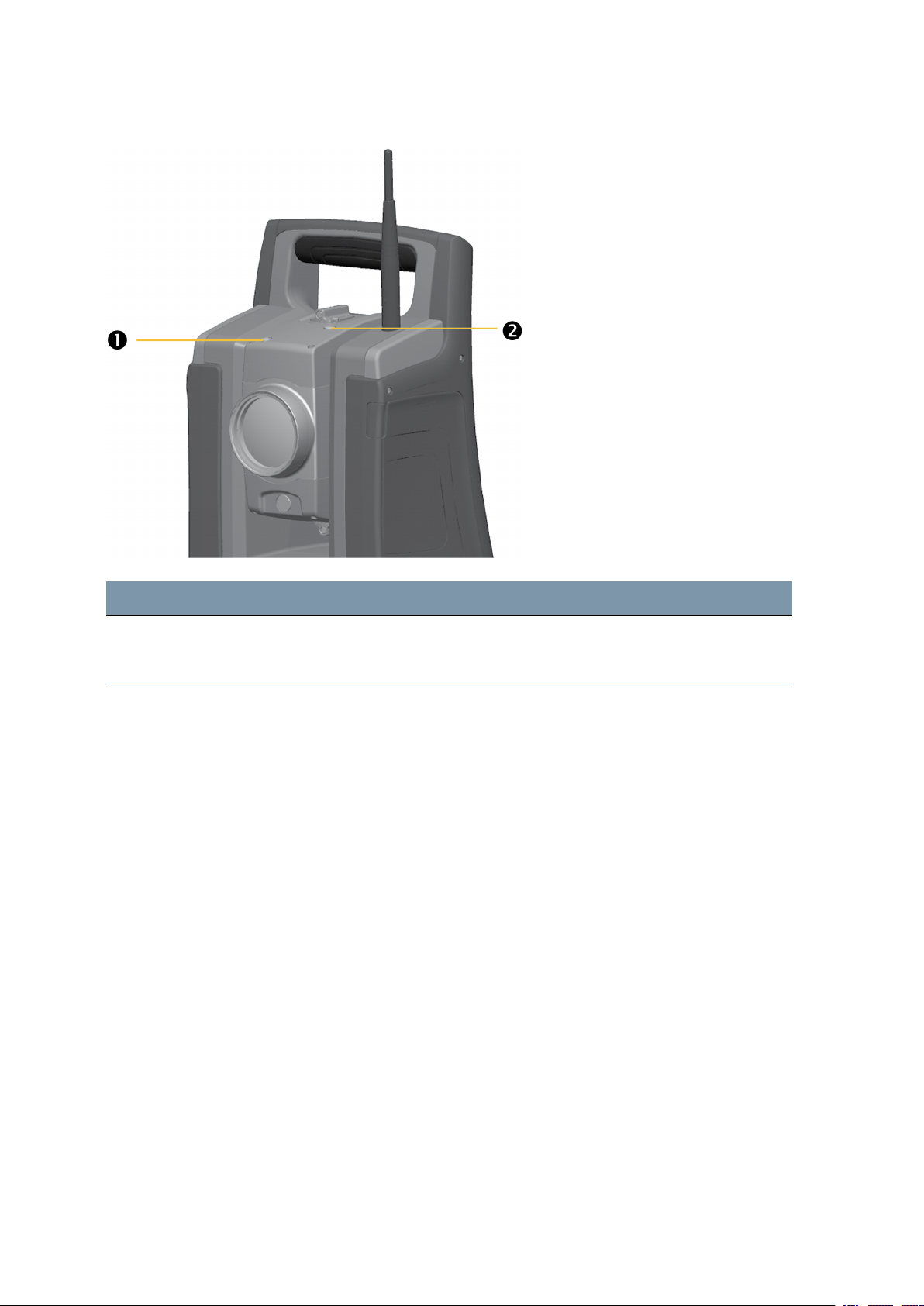
4 Setup
Item Description
Vertical pointer adjustment port
❶
Horizontal pointer adjustment port
❷
FOCUS 35 TotalStation User Guide | 74
Page 75
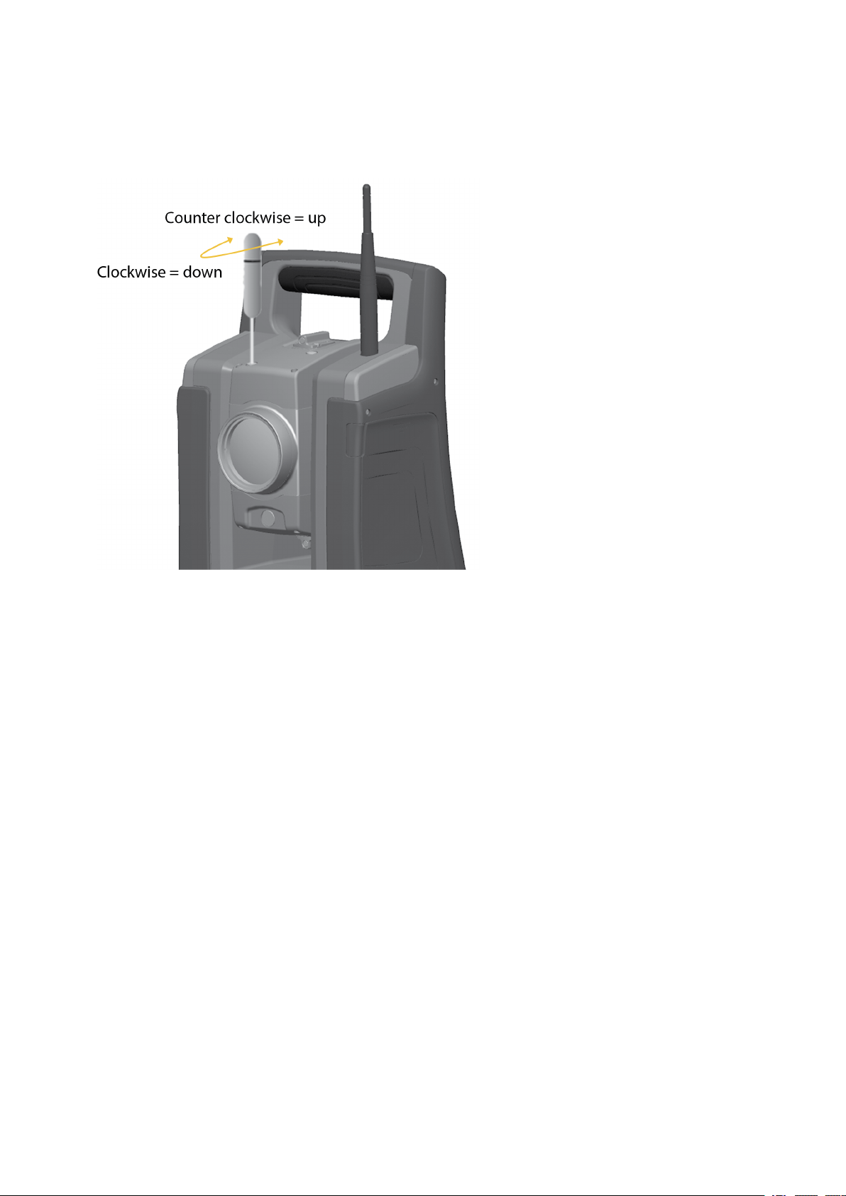
4 Setup
To correct the vertical position of the laser spot, insert the allen key into the vertical adjustment port
and turn it as shown:
FOCUS 35 TotalStation User Guide | 75
Page 76
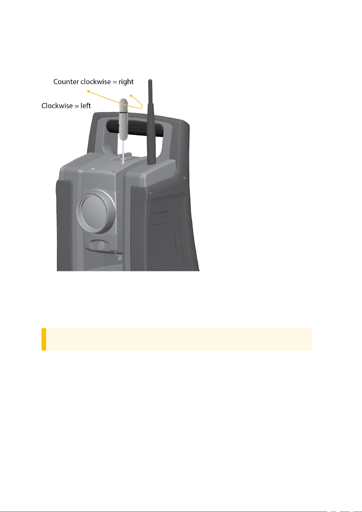
4 Setup
To correct the horizontal position of the laser spot, insert the allen key into the horizontal adjustment
port and turn it as shown:
Check the alignment of the laser spot and the cross-hairs. Throughout the adjustment procedure, keep
the telescope pointing to the adjustment target. The adjusting screws are of a high tension because they
are self locking. The screws tighten automatically after you adjust them.
Refit the plugs in the adjustment holes. Make sure that the plugs are correctly fitted for proper sealing
against the cover.
CAUTION – To keep out moisture and dust, make sure that the plugs are correctly fitted in the
adjustment ports.
FOCUS 35 TotalStation User Guide | 76
Page 77

Optical Plummet
1. Set up the instrument and level it over a ground mark so that the tripod height is 1.5 m (±0.1 m)
(4.920 ft (±0.328 ft)), see image below.
2. Note the position of the inner circle of the optical plummet in relation to the ground mark.
3. Turn the instrument 200 grads (180 degrees).
4. Note the position of the inner circle of the optical plummet in relation to the ground mark. If the
inner circle of the optical plummet reticle moves in relation to the ground mark, you must adjust the
plummet reticle location.
5. Adjust out half of the error with the four adjustments screws on the optical plummet.
6. Turn the instrument 200 grads (180 degrees).
7. If there is no movement between the inner circle of the optical plummet reticle in relation to the
ground mark, no further adjustment is needed.
CAUTION – When adjusting the optical plummet with the four adjustment screws it is important
that the screws are correctly adjusted. When one screw is adjusted the opposite screw must be
adjusted equally in the reverse direction, in order to keep the correct tension on the optics. Do not
overtighten the screws, this might damage the optics.
4 Setup
FOCUS 35 TotalStation User Guide | 77
Page 78
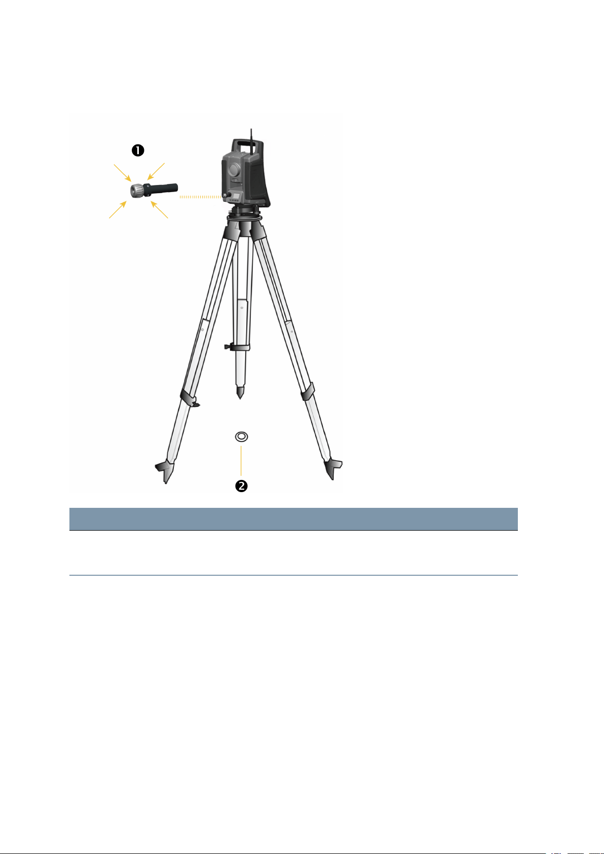
Optical plummet adjustment:
4 Setup
Item Description
Optical plummet reticle 4x adjustment screws
❶
Ground mark
❷
FOCUS 35 TotalStation User Guide | 78
Page 79
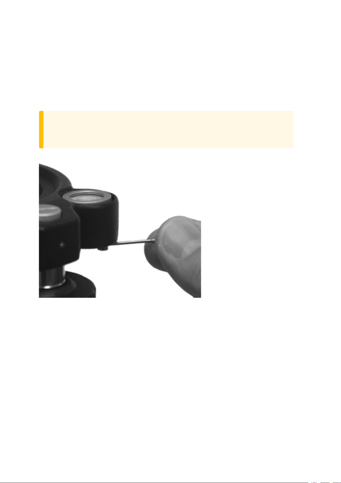
Tribrach Circular Level
1. Level the instrument with the electronic instrument bubble.
2. Remove the instrument from the tribrach.
3. Use the provided adjustment key and adjust the bubble with the three bubble screws. The bubble
must be centered.
CAUTION – When adjusting the Circular Level with the three adjustment screws it is important
that the screws are correctly adjusted. When one screw is adjusted the two opposite screw must
be adjusted equally in the reverse direction, in order to keep the correct tension on the Circular
level. Do not overtighten the screws.
Circular Level adjustment:
4 Setup
FOCUS 35 TotalStation User Guide | 79
Page 80
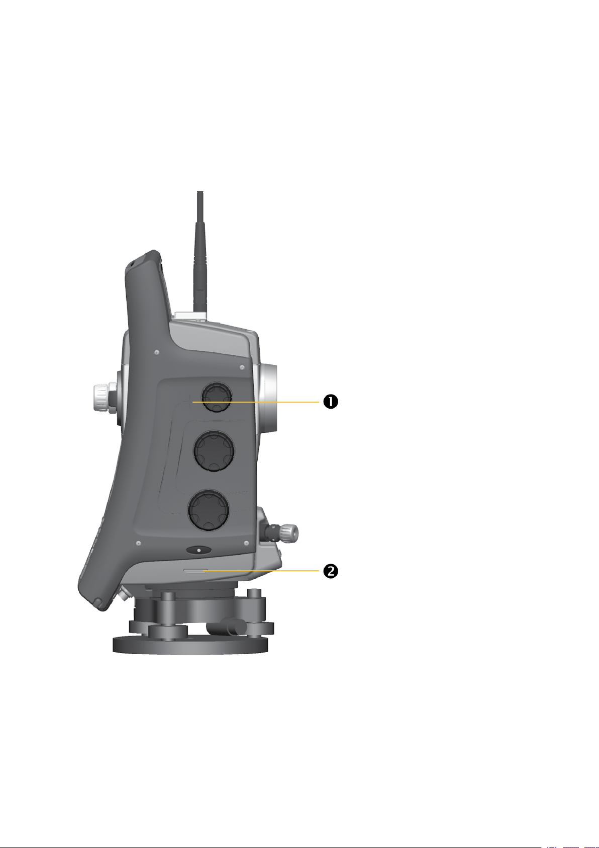
4 Setup
Measuring the Instrument Height
There are two measurement marks on the side of the instrument. The top mark ❶ corresponds to the
trunnion axis of the instrument. The bottom mark ❷ is 0.158 m (0.518 ft) below the top mark. Measure
the bottom mark to the top ridge of the mark.
Instrument height marks:
When the Survey Pro software is running, the software has additional functions that reduce the bottom
mark measurement to the required vertical instrument height to the trunnion axis, see image below and
the following paragraph.
FOCUS 35 TotalStation User Guide | 80
Page 81
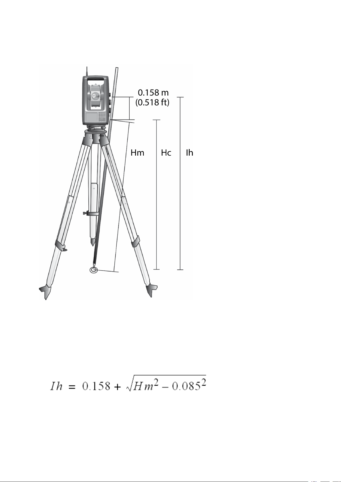
Instrument height measurement:
4 Setup
The measured distance (Hm) is corrected for the slope of the measurement to obtain a vertical
measurement to the bottom mark (Hc). The constant from the bottom mark to the top mark (0.158
m/0.518 ft) is added to the Hc to obtain the vertical instrument height from the ground mark to the
trunnion axis (Ih). For more information, refer to the Survey Pro documentation.
Alternatively, to obtain an accurate measurement to the top mark (Ih), you can manually measure the
slope distance from the ground to the bottom mark (Hm). To calculate the total instrument height (Ih),
insert the measured slope distance (Hm) into the formula below:
FOCUS 35 TotalStation User Guide | 81
Page 82

4 Setup
Pre Measurement Check List
Before you begin measurement or stake out operations, check the following items:
l Lenses are clean
l Instrument is correctly leveled and Trunnion axis tilt
l HA/VA Collimation error
l LockNGo Tracker collimation error (if the instrument is equipped)
l Laser Pointer beam alignment
l Correct radio channel is selected (robotic measurements only)
l Measure instrument height
l Allow sufficient time for the instrument to adjust to the ambient temperature, see Setup Stability
Connecting to an External Data Collector
The Ranger™, T41™, and Nomad® handhelds and the ST10 rugged tablet can be used as data collectors
for the FOCUS 35 Total Station.
The controller can be connected to the FOCUS 35 Total Station via Bluetooth® wireless technology or
radio.
Connecting with Cable - LockNGo Instrument Version
The controller is connected from the FOCUS 35 Total Station COM port to the USB or the RS-232
connector.
Controller Cable
Ranger 73840019-SPN or 53002021-SPN
Nomad 53002021-SPN
T41 67601-05 53002021-SPN
ST10 73840019-SPN
FOCUS 35 TotalStation User Guide | 82
Page 83
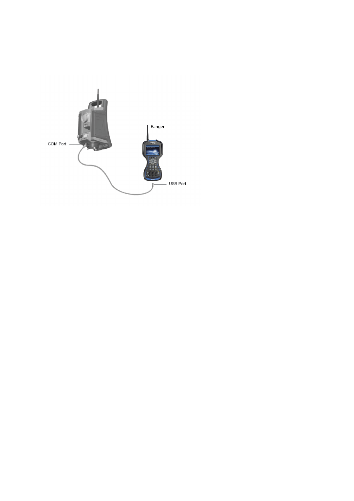
The image shows an external controller connected to the FOCUS 35 Total Station with cable for
measurements.
4 Setup
Connecting with Bluetooth wireless technology - LockNGo Instrument Version
The data collector is connected directly to the instrument via Bluetooth wireless technology.
All models of the FOCUS 35 Total Station can be connected to a Bluetooth-enabled controller, though
most configurations only allow for short-range communications. Beginning in July 2019, the LockNGo
version of the FOCUS 35 total station contains Class 1 Long Rage Bluetooth. When paired with a
controller that also has Class 1 Bluetooth this allows for communications over Bluetooth up to 200 m
away, without a radio.
Bluetooth range varies based on environmental conditions such as physical obstructions or interference
from other nearby devices. Range also varies based on the transmitter strength and receiver sensitivity
of both the controller and the FOCUS 35 total station.
LockNGo models whose part number begins with “7847” contain Class 1 Bluetooth. LockNGo models
whose part number begins with “7844” contain Class 2 Bluetooth.
Connecting with Radio - Robotic and RX Instrument Versions
The data collector is connected to the instrument via the radio using one of two methods:
l Integrated: Data collector with integrated radio, connected directly to the FOCUS 35 total station.
l Radio bridge: Data collector connected to a radio bridge (an external radio), which can
communicate with the FOCUS 35 total station. The external data collector is connected to the
external radio via Bluetooth wireless technology.
FOCUS 35 TotalStation User Guide | 83
Page 84

5
Instrument Operational Methods
Conventional Measurements with StepDrive Motor System
LockNGo Measurement
GeoLock Technology
Robotic Measurement
FOCUS 35 TotalStation User Guide | 84
Page 85

5 Instrument Operational Methods
Conventional Measurements with StepDrive Motor System
This chapter describes the following instrument operational methods for the FOCUS 35 Total Station:
l When combined with the application software:
l When setting/staking out, the instrument calculates and automatically aims towards the
calculated position of the selected point.
l The instrument will automatically point towards a selected reference target to check for
instrument movement during measurements.
l Instrument software corrects the collimation / trunnion axis tilt errors in real time.
l The StepDrive motor system are continuous and endless allowing for rapid repeat manual pointing of
the instrument with no end stops.
NOTE – To obtain the correct point location with the instrument, you must aim correctly to the
target.
LockNGo Measurement
Combining the StepDrive motor capability with the image-based tracking system provides the ability to
carry out LockNGo measurements. LockNGo enables the instrument to automatically lock on to a prism,
and then follow it precisely as it moves. This means that the instrument is taking care of the pointing,
and that position can be continuously updated as the target moves around the jobsite. LockNGo is
especially useful for carrying out rapid site topo measurements and during stakeout using a
conventional two-person crew. It is also exceptionally useful for working in poor visibility and darkness
conditions, and for automatically checking to reference targets during measurements.
GeoLock Technology
GeoLock™ technology is a feature of the Survey Pro software that allows a robotic total station to
perform an aided search for an optical target using an initial GNSS position. The technology greatly
reduces the time to locate and lock onto a target.
The GeoLock technique combines a GNSS position with the FOCUS 35 robotic total station and the
robotic roving operator. The remote instrument can then be directed towards the robotic roving
operator using the GNSS position and a subsequent search is quickly performed to reacquire the target
at the robotic rover.
Robotic Measurement
Combining the StepDrive motor capability with the image-based tracking system and the radio capability
enables the instrument to carry out measurements robotically. This enables a single operator to control
the instrument and carry out measurements or set/stakeout from the rod at the point.
FOCUS 35 TotalStation User Guide | 85
Page 86

Instrument Technology
Angle Measuring Technology
Distance Measuring Technology
Tracklight
StepDrive Motor System and Focus System
LockNGo Tracking Technology
Power Management
Instrument
Robotic Configuration
6
Power Supply
External Communication
Radio
Bluetooth wireless technology
FOCUS 35 TotalStation User Guide | 86
Page 87

6 Instrument Technology
Angle Measuring Technology
The principles of angle measurement are based on reading an integrated signal over two opposite areas
of the graduated circle and producing a mean angular value. This eliminates inaccuracies caused by
eccentricity and graduation.
In addition, the angle measurement system compensates for the following automatic corrections:
l Instrument mislevelment (deviation of the plumb axis).
l Horizontal and vertical collimation error.
l Trunnion axis tilt, see Correction for Trunnion Axis, page 89.
Correction for Mislevelment
The FOCUS 35 Total Station automatically corrects for mislevelments up to ±5.5’. The instrument warns
the operator immediately of any mislevelments in excess of ±5.5’ (±0.1 grads).
Corrections for the horizontal angle, vertical angle, and slope distance are calculated in the field
application software and applied to all measurements.
Compensator Calibration
The calibration process involves the instrument automatically reading the compensator value at a series
of predetermined positionsthrough the full rotation of the instrument. The process takes approximately
one minute to complete. During the process the instrument should be on a stable platform, free from
vibration and untouched by the user.
Spectra Geospatial recommends that you regularly carry out a compensator calibration, especially in the
following situations:
l Whenever the instrument may have been roughly handled during transport.
l When the ambient temperature differs by more than 10 °C (18 °F) from the previous calibration test
temperature.
l Immediately prior to high precision angle measurements in one face.
Correction for Collimation Errors
HA/VA Collimation
The horizontal collimation error is the deviation of the sighting axis from its required position at right
angles to trunnion axis.
The vertical collimation error is the difference between the vertical circle zero and the plumb axis of the
instrument.
Traditionally, collimation errors were eliminated by observing angles in both instrument faces. In the
FOCUS 35 Total Station, a pre-measurement collimation test is performed to determine the collimation
errors. Angular measurements are observed in both instrument faces, the collimation errors are
calculated, and the respective correction values are stored in the instrument. The collimation correction
FOCUS 35 TotalStation User Guide | 87
Page 88

6 Instrument Technology
values are then applied to all subsequent angle measurements, including the distance related focus lens
collimation error. Angles observed in a single face are corrected for collimation errors, which eliminates
the need to measure in both instrument faces.
Carry out a collimation test in the following situations:
l Whenever the instrument may have been roughly handled during transport.
l When the ambient temperature differs by more than 10 °C (18 °F) from the previous collimation test
temperature.
l Immediately prior to high precision angle measurements in one face.
FOCUS 35 Total Station with LockNGo Tracker
A FOCUS 35 Total Station with LockNGo capability can automatically lock and track a prism target as it
moves. Pointing errors caused by slight misalignment of the instrument’s tracker have a similar effect to
the HA and VA Collimation errors as detailed above.
To correct for the tracker collimation errors, carry out a LockNGo Tracker collimation test. The
LockNGo Tracker collimation test automatically observes angular measurements to a target in both
faces, the tracker collimation errors are calculated and the respective correction values are stored in
the instrument.
The collimation correction values are then applied to all subsequent angle measurements observed when
LockNGo Tracker is enabled. Angles observed in a single face are corrected for collimation errors, which
removes the need to measure in both instrument faces.
Carry out a LockNGo Tracker collimation test in the following situations:
l Whenever the instrument may have been roughly handled during transport.
l When the ambient temperature differs by more than 10 °C (18 °F) from the previous collimation test
temperature.
l Immediately prior to high precision angle measurements in one face.
FOCUS 35 TotalStation User Guide | 88
Page 89
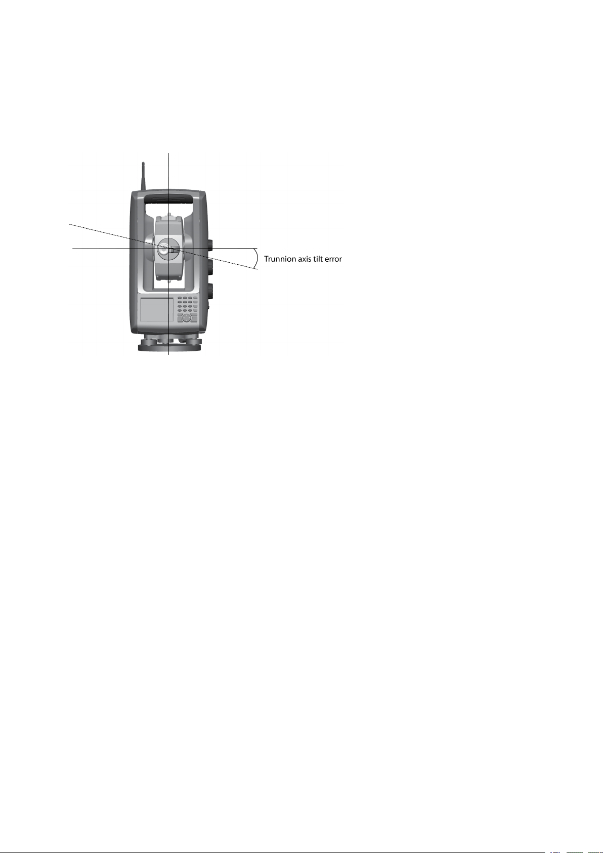
6 Instrument Technology
Correction for Trunnion Axis
The trunnion axis tilt error is the deviation of the trunnion axis of the telescope from its required position
at right angles to the plumb axis of the instrument.
In the FOCUS 35 Total Station, perform a pre-measurement trunnion axis tilt test to determine the
trunnion axis tilt error. Angular measurements are observed in both instrument faces, the trunnion axis
tilt error is calculated, and the respective correction value is stored in the instrument. The trunnion axis
tilt correction value is then applied as a correction to the horizontal angle value.
l Carry out a trunnion axis tilt test in the following situations:
l Whenever the instrument may have been roughly handled during transport.
l When the ambient temperature differs by more than 10 °C (18 °F) from the previous collimation test.
l Immediately prior to high precision angle measurements in one face.
Averaging Measurements to Reduce Sighting Errors
The FOCUS 35 Total Station automatically reduces sighting errors caused by the misalignment of the
instrument to the target or by pole movement during measurement.
The following techniques can be used:
l Use LockNGo Tracker. When LockNGo Tracker is enabled, the instrument automatically locks onto
and tracks the target. Manual sighting errors are reduced.
l Automatically average angles during distance measurement. When measuring in Standard mode,
the instrument takes angle measurements while measuring the distance. Angles returned to the
instrument at 200 Hz, are averaged over this period to obtain an averaged angle measurement.
l Use average measurement methods in the field software.
FOCUS 35 TotalStation User Guide | 89
Page 90

6 Instrument Technology
Distance Measuring Technology
Spectra Geospatial FOCUS 35 Total Stations are equipped with a combined distance unit. This means
that the instrument can measure to a prism or to normal surfaces (reflectorless mode).
The laser distance unit is based on the phase comparison method. The distance unit is coaxial with the
line of sight and transmits an intensity modulated optical measuring beam that is reflected by a prism or
scattered by a natural surface on which the beam is directed. The phase difference between the
transmitted light and the reflected received light is detected and represents the distance.
In prism mode, the unit operates as a fast and precise long-range distance meter. In reflectorless mode,
the unit transmits a collimated visible red laser beam to the target point and then calculates the
distance between the transmitted and the received light.
The distance unit software will detect erroneous single distance measurements such as those caused by
an obstruction passing through the measurement beam, and will ignore such readings in the
computation of the final distance.
The unambiguous range for distance measurement is as follows:
l Prism mode - 7,350 m (24,114 ft)
l Reflectorless mode - 1,100 m (3,609 ft)
NOTE – Do not measure to a prism in reflectorless mode. Distances up to 1100 m (3,609 ft) are not
allowed because a Class 3 Laser is used for reflectorless distance measurement. For distances
longer than 1100m (3,609 ft), the instrument's distance accuracy is not guaranteed.
FOCUS 35 TotalStation User Guide | 90
Page 91
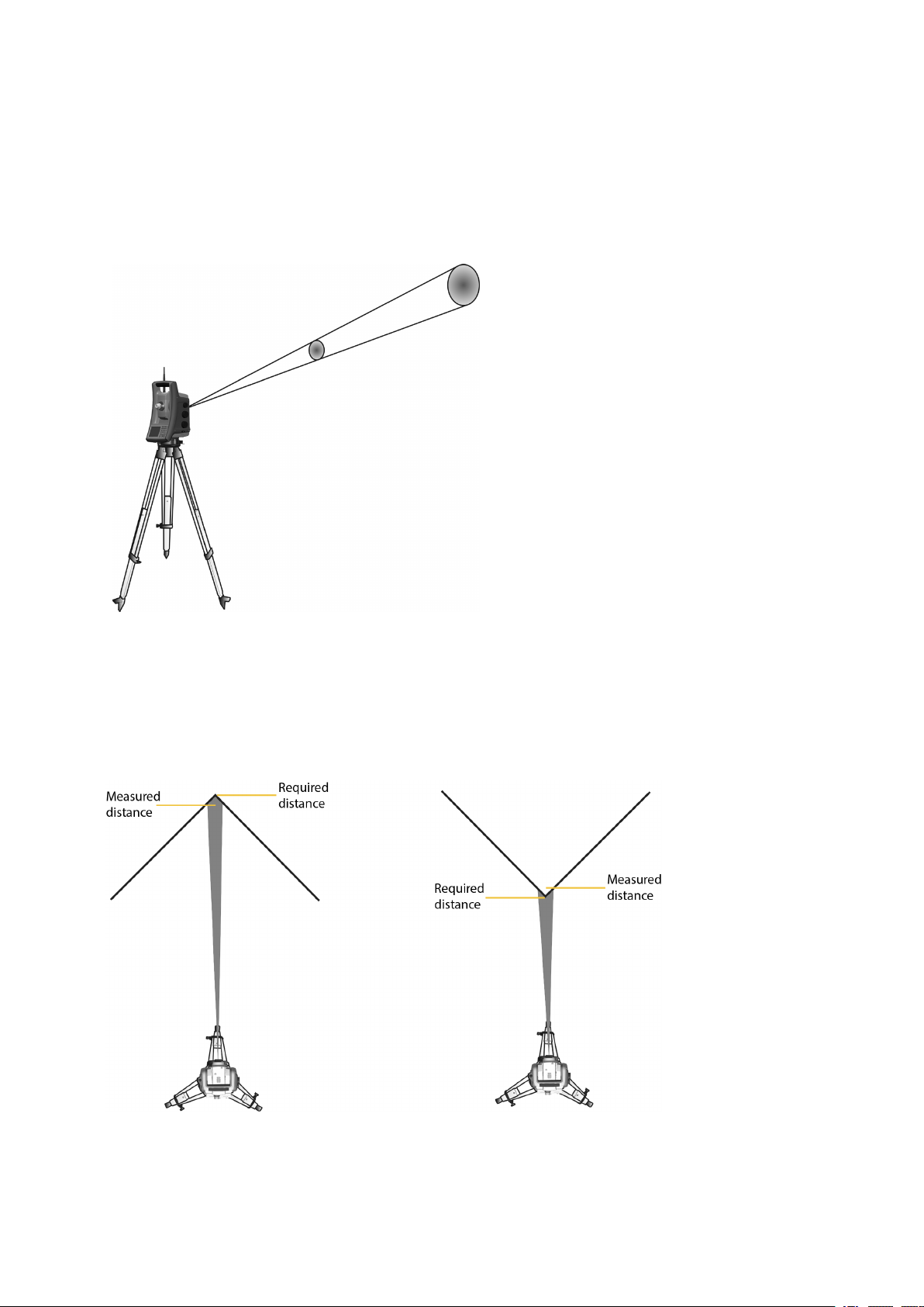
6 Instrument Technology
Beam Divergence
All distance meter measurement beams diverge as the range from the instrument increases. The
divergence of the distance meter beam relates to an increase in the size of the area being sampled, not
to a degradation of the measurement precision.
A larger measuring area at longer range is generally better because it enables smaller objects, such as
power lines and antennas, to be detected and accurately measured. With a smaller measuring area,
these small objects can be easily missed. A smaller measuring area has advantages when measuring
tight corners and vertices at close range. When observing measurements to a tight corner, the distance
meter beam divergence introduces a range error caused by the size of the sampling area.
Measuring to an inner and outer corner:
FOCUS 35 TotalStation User Guide | 91
Page 92
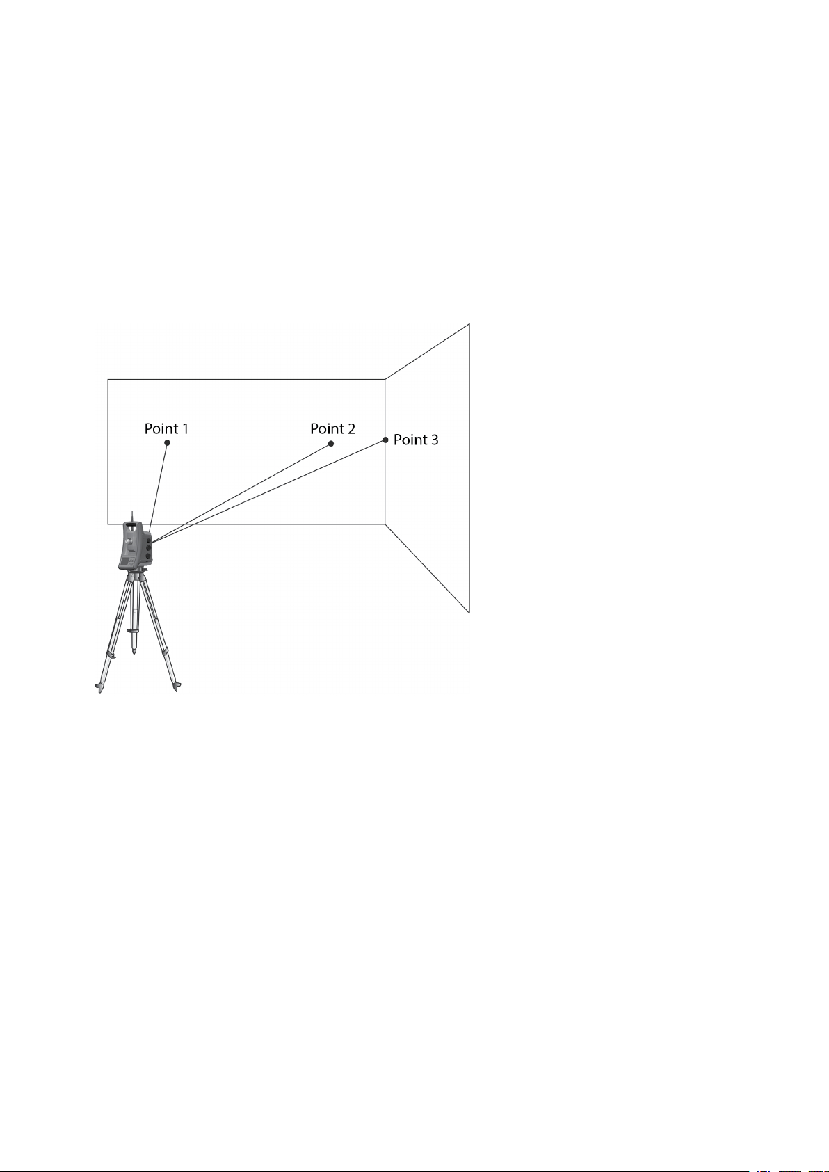
6 Instrument Technology
Although the problem is reduced with a beam that uses a smaller measuring area, the error can not be
completely eliminated. The most accurate solution to measure to tight corners and eliminate errors
caused by beam divergence, is to use an offset measurement method such as that used in the field
application software.
Do the following:
1. Measure two points on the face of the building.
2. Aim the instrument at the corner to store the correct horizontal and vertical angle.
Offset measurement:
With offset measurements, you can accurately measure difficult locations in reflectorless mode and
eliminate beam divergence errors. For more information, refer to the field application software
documentation.
FOCUS 35 TotalStation User Guide | 92
Page 93
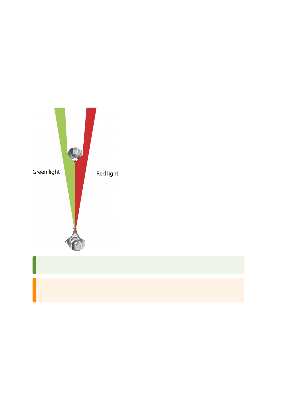
6 Instrument Technology
Tracklight
Tracklight is a visible guide light that enables the rod holder to position themselves into the instruments
current line of sight. The tracklight can be used during stakeout in all operational modes, and is also of
great benefit when operating in robotic mode as a means of checking that the instrument is tracking, or
when trying to reacquire lock by walking into the sight line of the LockNGo Tracker, or using the remote
joystick control in robotic mode. Tracklight consists of a flashing two-colored light, with each color lying
in its own lateral projection sector. If the rod holder is to the left of the measuring beam, they will see a
red flashing light; if they are to the right, they will see a green flashing light.
TIP – You can use the tracklight for clearing sight lines and as an aid to find prisms in the dark or
unfavorable sighting conditions.
WARNING – Do not use the Laser Pointer as an aid when searching for prisms, the reflected light
can dazzle your eyes. The reflected light will not damage your eyes, but might be uncomfortable,
see also Laser Safety, page 4.
FOCUS 35 TotalStation User Guide | 93
Page 94
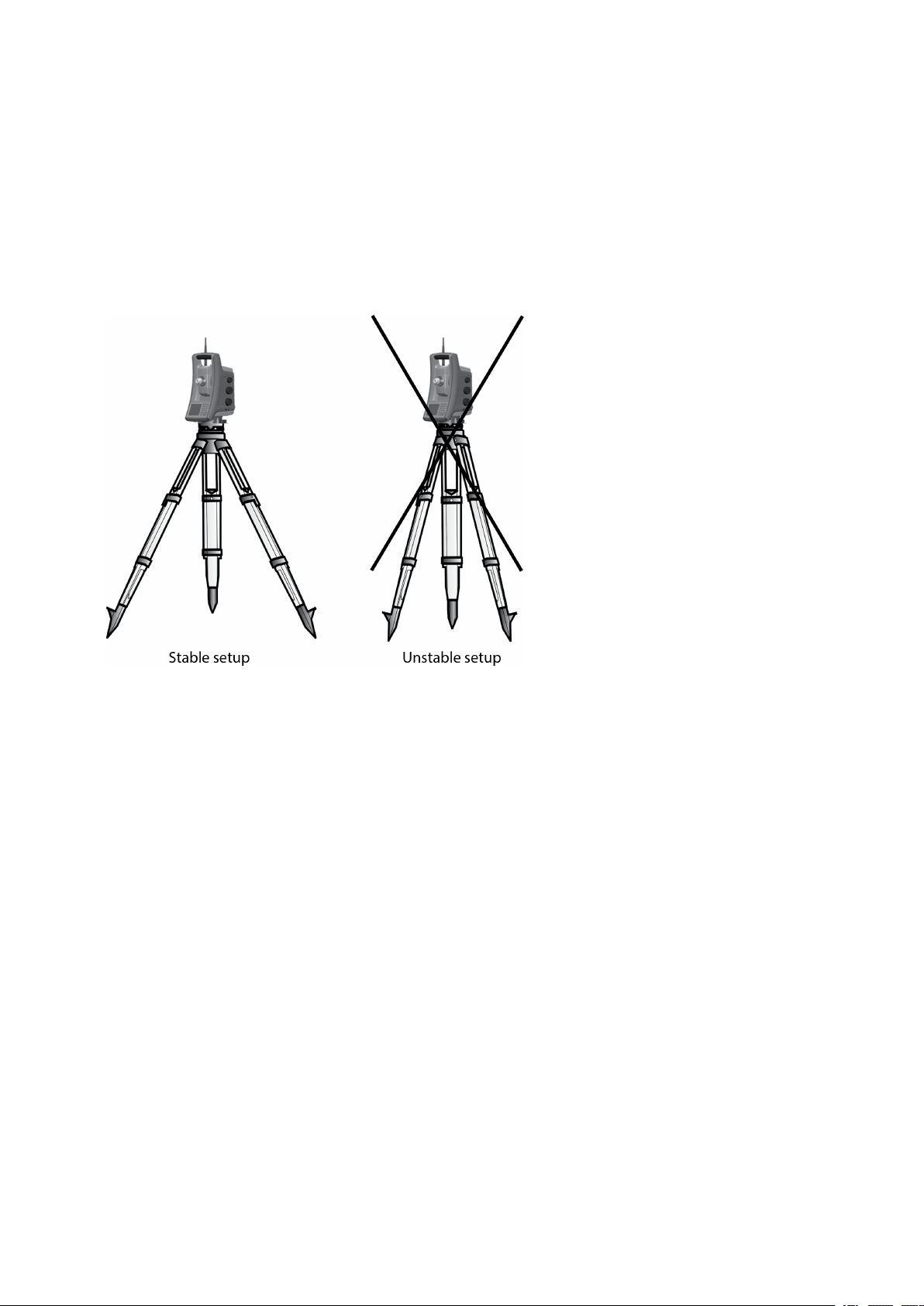
6 Instrument Technology
StepDrive Motor System and Focus System
The FOCUS 35 Total Station is equipped with a StepDrive motor system to position the instrument and
the telescope and a servo drive to focus the telescope.
Due to the instrument accuracy it is important to use a high quality tripod and tribrach. It is also
important to set up the tripod in a position for best stability, as shown. An unstable setup that could
negatively influence the resulting measurement precision.
FOCUS 35 TotalStation User Guide | 94
Page 95
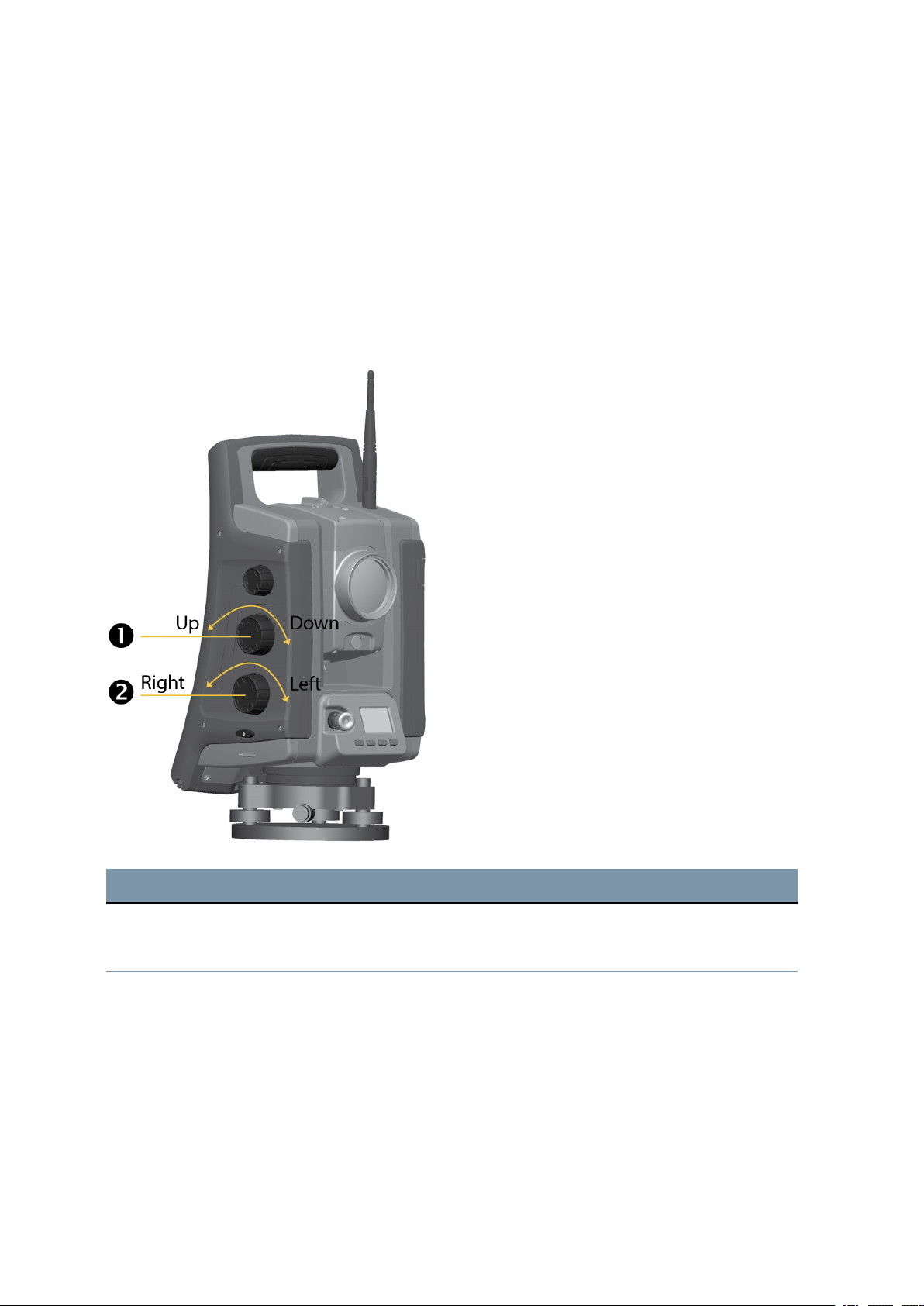
6 Instrument Technology
StepDrive
The StepDrive motor system is a mechanical rough-fine drive system, which gives high turning speeds
and accuracy. The system provides endless horizontal and vertical motion, including endless fine
adjustment. The instrument uses a StepDrive motor system when performing a number of different
operations such as turning the horizontal and vertical motion knobs, for automatic test and calibration,
or when using LockNGo Tracker technology for robotic surveying, see image below.
Please see also Settings for Drive Mode, page 66.
Position StepDrive motion knobs:
Item Description
Vertical motion knob
c
Horizontal motion knob
d
Focus System
The instrument is equipped with a motor focus drive. The focus motion knob is on the side of the
instrument for easy access.
FOCUS 35 TotalStation User Guide | 95
Page 96
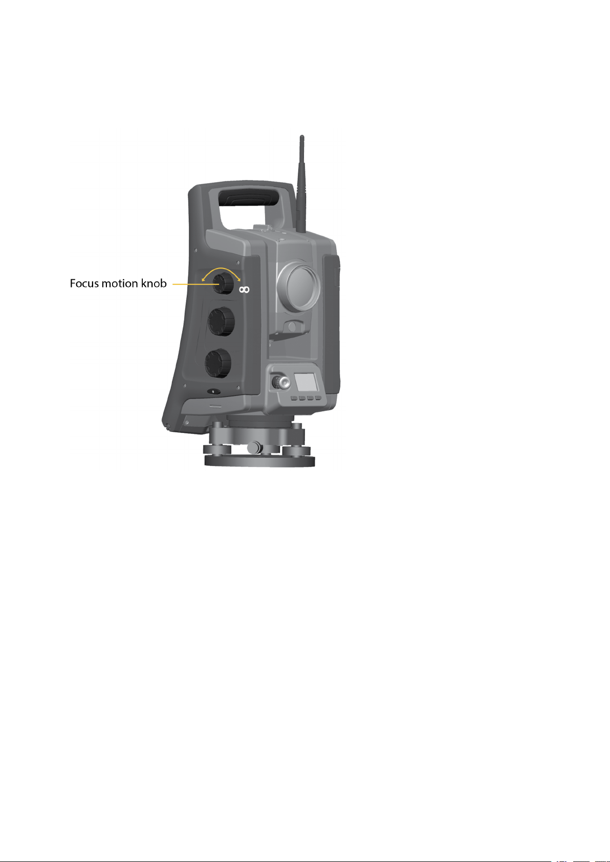
6 Instrument Technology
The focus knob is connected to a servo motor that is built into the telescope. When you turn the focus
motion knob, the servo motor adjusts the focusing lens.
FOCUS 35 TotalStation User Guide | 96
Page 97
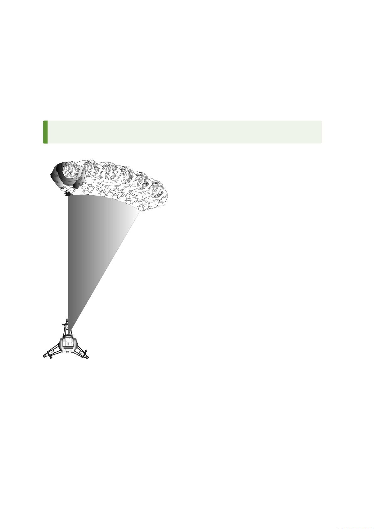
6 Instrument Technology
LockNGo Tracking Technology
The FOCUS 35 Total Station is equipped with an image-based tracking system, which is used for robotic
or conventional measurements to lock onto and track a prism.
LockNGo tracking technology controls the instrument StepDrive motor systems and aims the instrument
correctly towards the target.
TIP – To assure maximum performance from the LockNGo tracking technology keep the lens
clean and dry.
The FOCUS 35 Total Station LockNGo tracking function:
The FOCUS 35 Total Station can lock onto and track a prism.
Power Management
The power management in the FOCUS 35 Total Station instrument can set the instrument to one of three
different modes.
l Off Mode
l On Mode - all instrument functions
l Suspend Mode - to save power and replace empty battery
FOCUS 35 TotalStation User Guide | 97
Page 98

6 Instrument Technology
NOTE – Saving power is also possible with an economical use of the Control Unit Face1 Backlight,
for settings see Display Backlight Face1 Control Unit, page 33.
Instrument
Off Mode
l Press the Trigger key for 1 second (single beep) to turn on the instrument.
NOTE – During Off Mode the Trigger key LED is off.
On Mode
l When starting the instrument it will enter a Waiting mode, where it will wait for an external
connection for about 5 minutes. While in waiting mode the Trigger key LED will flash once every
second and Face2 Display will show “Waiting”. During this time it is possible to start the application
program, or prepare the settings for robotic measurements. The StepDrive motor system and Focus
System are usable during this time.
l If the instrument is not used for 5 minutes (default) the instrument will go to Suspend Mode and
Face2 display will show “Waiting (suspend)”.
l To turn Off the instrument press the Trigger key for 3 seconds - one beep and one double beep.
l The instrument will automatically enter Suspend Mode when the battery (including he Face 1
battery, if available) is removed.
l The instrument will go to Suspend Mode if the battery is low (battery capacity less than 5%), which
enables you to replace the battery within a period of 10 to 15 minutes.
l Without replacing the battery the instrument will go to Off Mode if the battery capacity is less than
2% and any unsaved data will be lost.
NOTE – During On Mode the Trigger key LED will be on solid.
Suspend Mode
l You can resume working from the same place in the software that you were before you entered
Suspend Mode.
l You can replace a discharged battery with a charged one within a period of 30 seconds.
l In the suspend mode the Radio and the Face2 display will be enabled. Face2 display will show
“Waiting (suspend)”.
l To turn the instrument On, press the Trigger key for one second (one beep) or connect to the
instrument from a remote application.
l To turn the instrument Off, press the Trigger key for 3 seconds.
l In Suspend Mode the instrument will turn Off automatically at suspend time out (default 120
minutes).
FOCUS 35 TotalStation User Guide | 98
Page 99

6 Instrument Technology
NOTE – During Suspend Mode the Trigger key LED will flash once every five seconds.
Robotic Configuration
A separate control unit is via cable or radio connected with the instrument. For starting the instrument
see Instrument, page 98.
On Mode
l If the instrument is controlled by a separate controller the instrument will not go into Suspend Mode
while the battery is charged.
l For setting the instrument to suspend mode shut down the radio or cable connection between
instrument and separate control unit, and the instrument will enter suspend mode. The instrument
will turn Off automatically at suspend time out (default 120 minutes).
l The instrument will go to Suspend Mode if the instrument battery is low (battery capacity less than
5%), which enables you to replace the instrument battery within a period of 10 - 15 minutes with
detailed information and warnings.
l Without replacing the battery the instrument will go to Off Mode if the battery capacity is less than
2%.
Power Supply
The power management in the FOCUS 35 Total Station has been designed to deliver the most operating
time in the field. The power management system includes the internal battery, optional external power
supply and the battery charger.
Internal Power Supply
The primary power supply for the FOCUS 35 Total Station is a rechargeable, removable Lithium-ion
battery.
Second Internal Power Supply
On available models, a second internal battery can be inserted in the Face 1 battery compartment. This
battery is treated as an external power source and power is used from this battery before the main
internal battery is used.
External Power Supply
The FOCUS 35 Total Station has one external port in the base of the instrument for communication and
for external power supply. External power can be provided by a car battery with an appropriate cable.
FOCUS 35 TotalStation User Guide | 99
Page 100

6 Instrument Technology
External Communication
The communication port on the base of the FOCUS 35 Total Station can be used for external
communications to a computer or data collector.
CAUTION – Use only the gray cables with 6-pin Hirose connectors from Spectra Geospatial when
connecting a cable to the instrument.
Radio
The FOCUS 35 Total Station (Robotic and RX versions) has an internal radio to support robotic operations.
The internal radio is a 100 mW radio that operates in the public free 2.4 GHz band. The radio uses
frequency hopping technology to reduce radio interference and maintain radio communications in even
the harshest RF environment. The FOCUS 35 Total Station radio baud rate is 115200 bps. This high baud
rate reduces the measurement latency, which ensures that a measurement viewed at the pole is
received 100 msec after the measurement is sent from the instrument.
To maintain radio communication with the instrument, the controller at the pole must also be connected
to a 2.4 GHz external radio or have an internal radio. The Ranger 7 and Ranger 3 handhelds are available
with 2.4 GHz radios.
Bluetooth wireless technology
The FOCUS 35 Total Station can also use Bluetooth wireless technical for external communications. The
Bluetooth baud rate is 115200 bps.
FOCUS 35 TotalStation User Guide | 100
 Loading...